

Page 1

DOCUMENT FEEDER
(DF Type 55)
Page 2
1 July, 1998 MECHANICAL COMPONENT LAYOUT
1. SPECIFICATIONS
Original Size: Standard Sizes A3 to A5
Non-standard Sizes
Max. width 297 mm
Min. width 105 mm
Max. length 864 mm
Min. length 128 mm
Original Weight : 45 g to 90 g
Table Capacity : 30 sheets (using 20 lb or 80 g/m2 paper)
Original Standard Position: Rear left corner
Separation: FRR
Original Transport: Roller transport
Original Feed Order: From top original
Reproduction Range: 50 to 155%
Power Source: 24 & 5 V dc from the copier
Power Consumption: 25 W
Dimensions (W x D x H): 550 x 470 x 120 mm
Weight: 9 kg
C578-1
Options
Page 3
MECHANICAL COMPONENT LAYOUT 1 July, 1998
2. COMPONENT LAYOUT
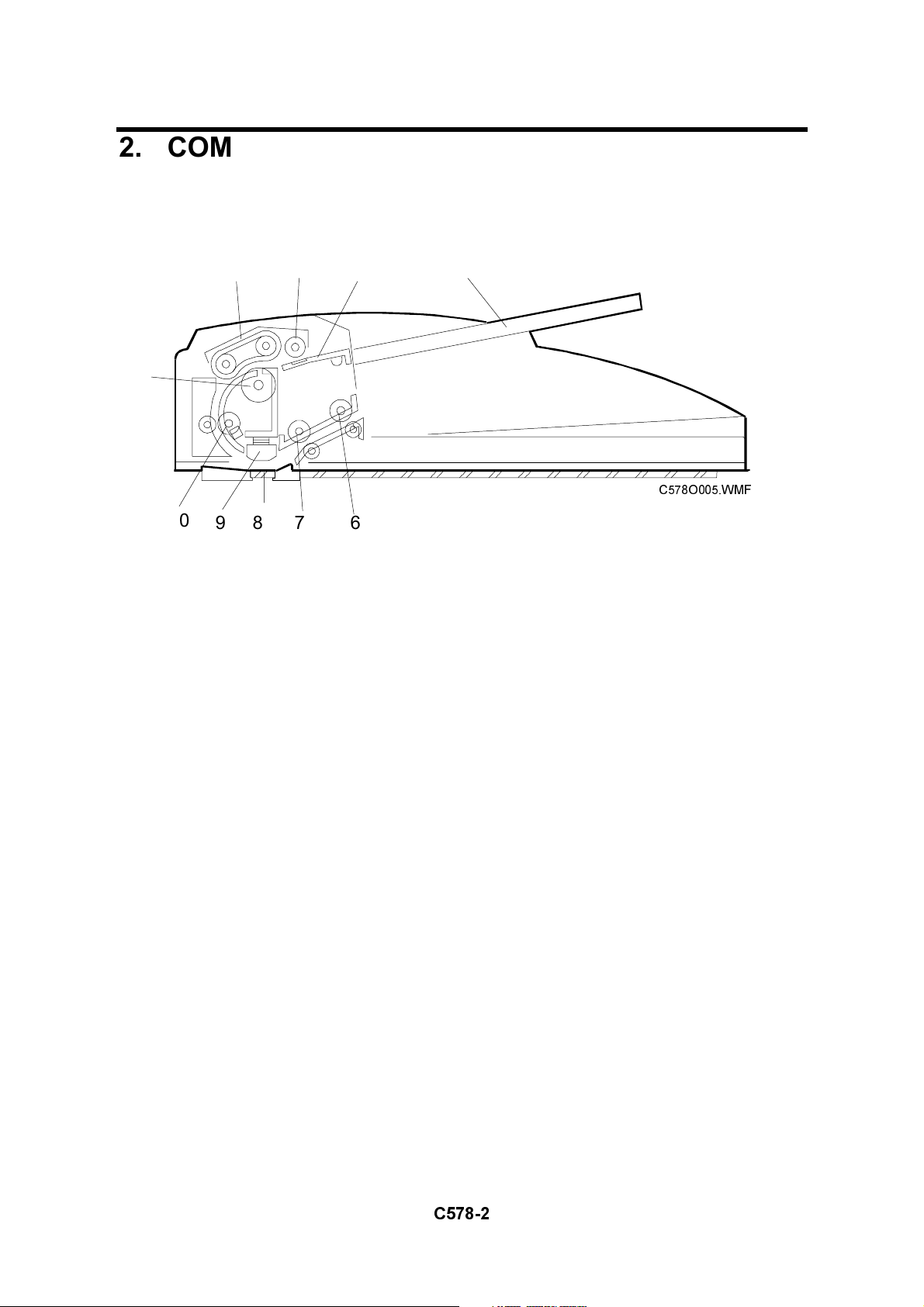
2.1 MECHANICAL COMPONENT LAYOUT
1
10
98 7 6
1. Separation Roller
2. Paper Feed Belt
3. Pick-up Roller
4. Original Entrance Guide
5. Original Table
432
5
C578O005.WMF
6. Original Exit Roller
7. 2nd Transport Roller
8. DF Exposure Glass
9. Original Exposure Guide
10. 1st Transport Roller
C578-2
Page 4
1 July, 1998 ELECTRICAL COMPONENT LAYOUT
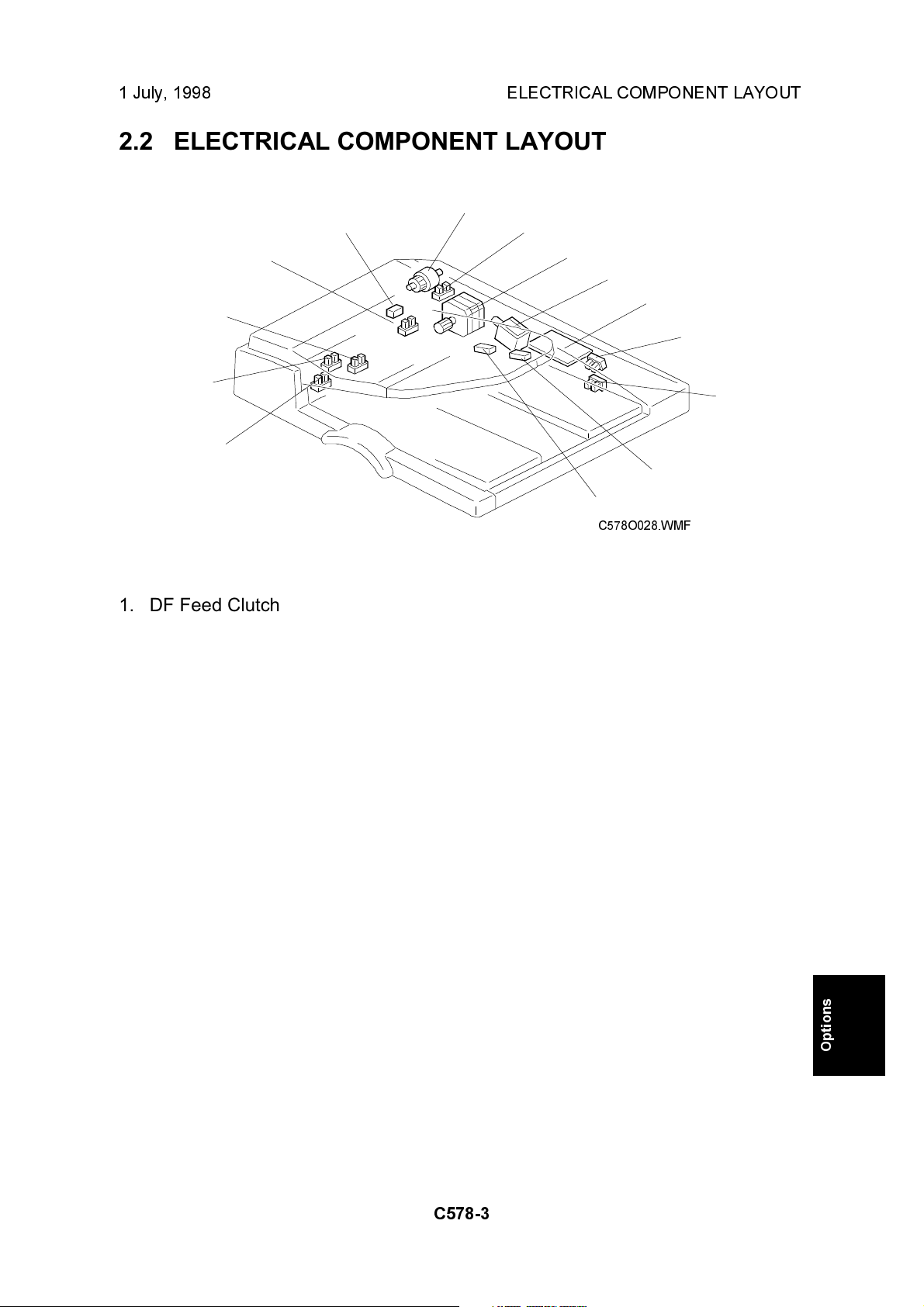
2.2 ELECTRICAL COMPONENT LAYOUT
1
14
13
12
2
3
4
5
6
11
10
1. DF Feed Clutch
2. Feed Cover Open Sensor
3. DF Feed Motor
4. DF Pick-up Solenoid
5. DF Drive PCB
6. DF Position Sensor
7. APS Start Sensor
8. Original Length Sensor 2
7
8
9
C578O028.WMF
9. Original Length Sensor 1
10. Original Width Sensor 3
11. Original Width Sensor 2
12. Original Width Sensor 1
13. Original Set Sensor
14. Registration Sensor
C578-3
Options
Page 5
ELECTRICAL COMPONENT DESCRIPTION 1 July, 1998
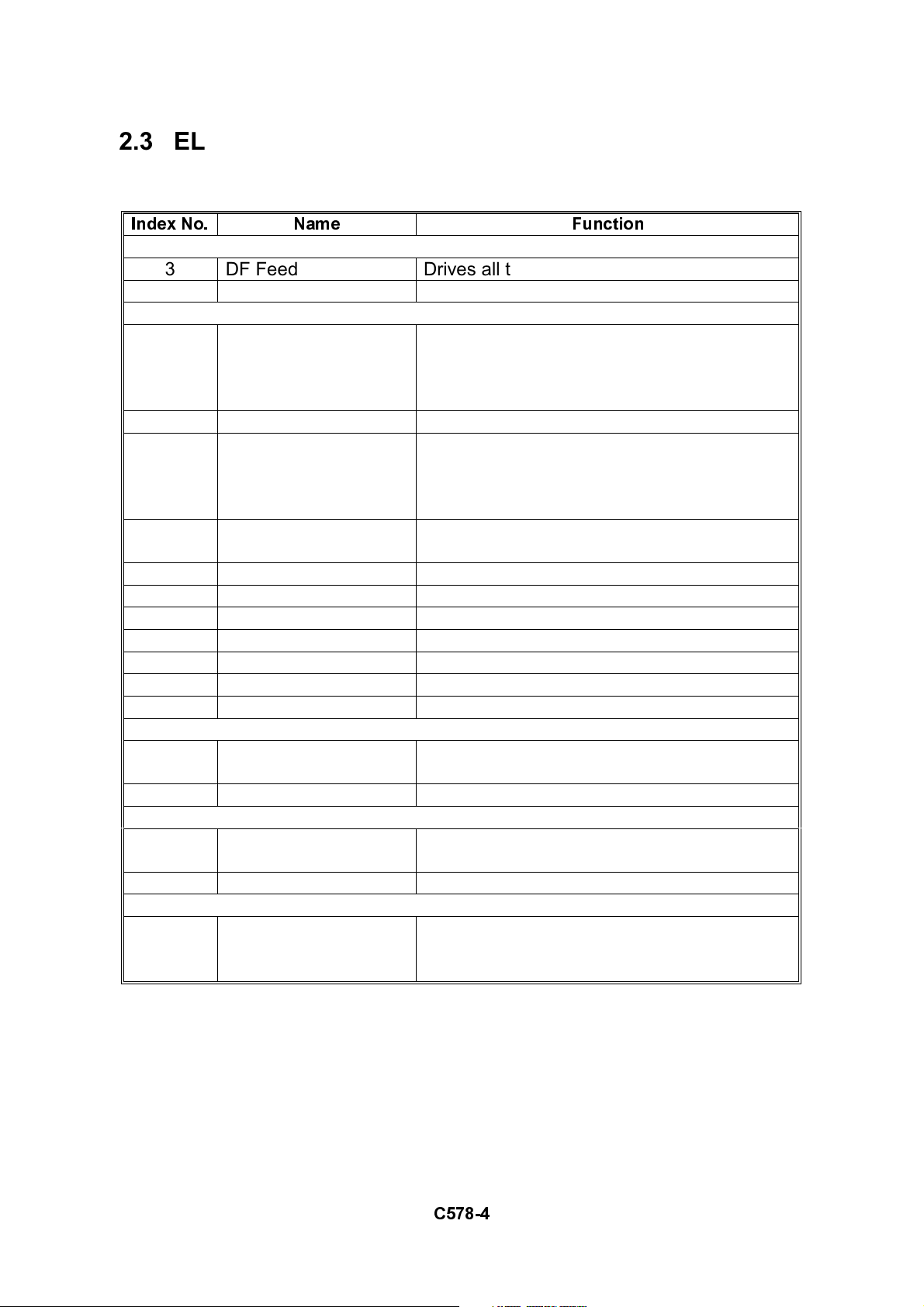
2.3 ELECTRICAL COMPONENT DESCRIPTION
Table
Index No. Name Function
Motors
3 DF Feed Drives all the rollers.
Sensors
7 APS Start Informs the CPU when the DF is opened
and closed (for platen mode) so that original
size sensors in the copier can check the
original size.
6 DF Position Detects whether the DF is lifted or not.
14 Registration Detects the leading edge of the original to
turn off the transport motor, detects the
original exposure timing, and checks for
original misfeeds.
2 Feed Cover Open
Sensor
12 Original Width - 1 Detects the original width
11 Original Width - 2 Detects the original width
10 Original Width - 3 Detects the original width
9 Original Length - 1 Detects the original length.
8 Original Length - 2 Detects the original length.
13 Original Set Detects if an original is on the feed table.
Detects whether the feed-in cover is opened
or not.
Solenoids
4 DF Pick-up Controls the up-down movement of the
original table.
Clutches
1 DF Feed Transfers transport motor drive to the pick-
up roller and feed belt.
Boards
5 DF Drive Interfaces the sensor signals with the copier,
and transfers the magnetic clutch, solenoid
and motor drive signals from the copier.
C578-4
Page 6
1 July, 1998 DRIVE LAYOUT
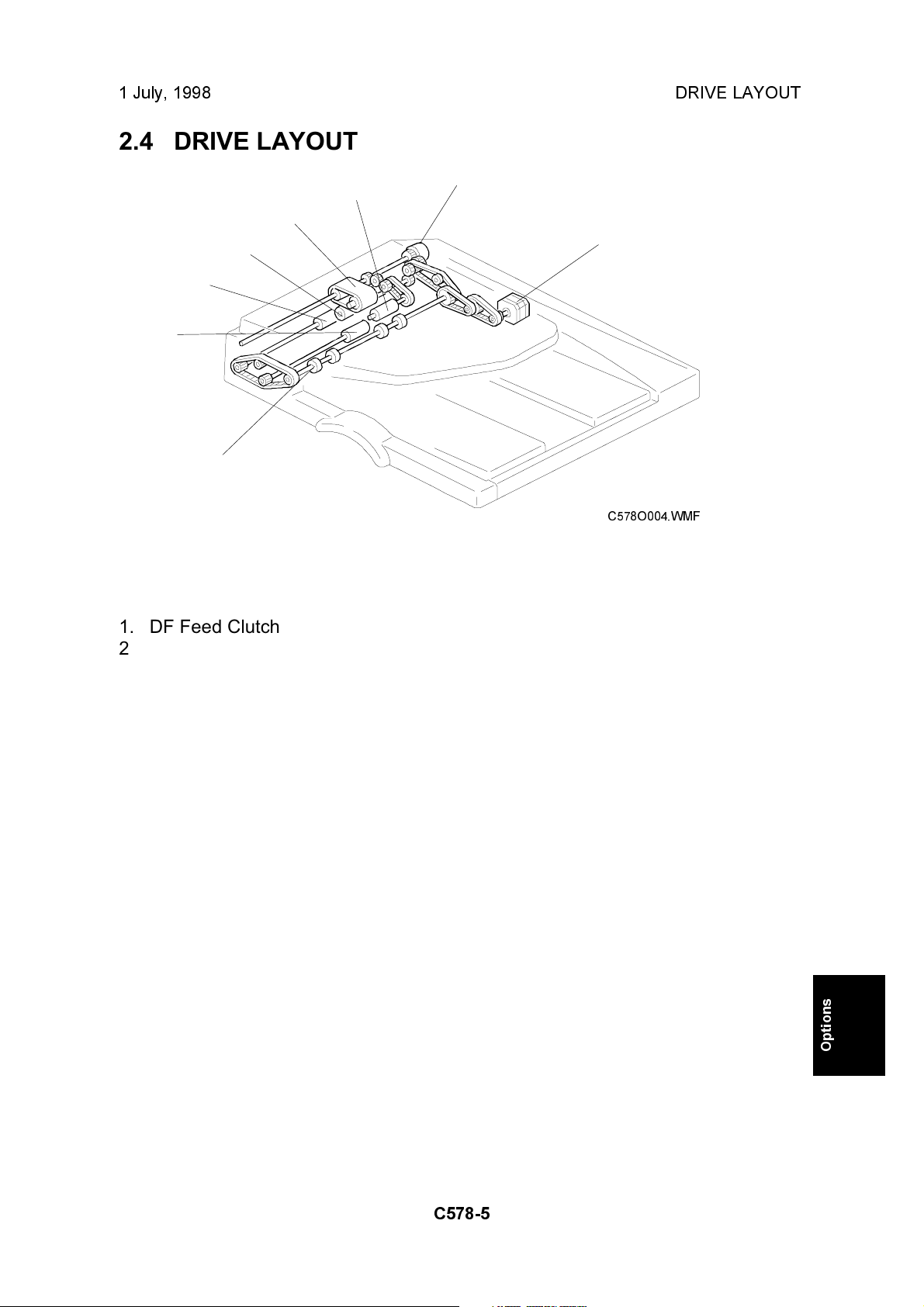
2.4 DRIVE LAYOUT
7
6
5
4
3
1. DF Feed Clutch
2. DF Feed Motor
3. Exit Roller
4. 2nd Transport Roller
8
1
2
C578O004.WMF
5. 1st Transport Roller
6. Separation Roller
7. Original Feed Belt
8. Pick-up Roller
C578-5
Options
Page 7
ORIGINAL SIZE DETECTION 1 July, 1998
3. DETAILED DESCRIPTIONS
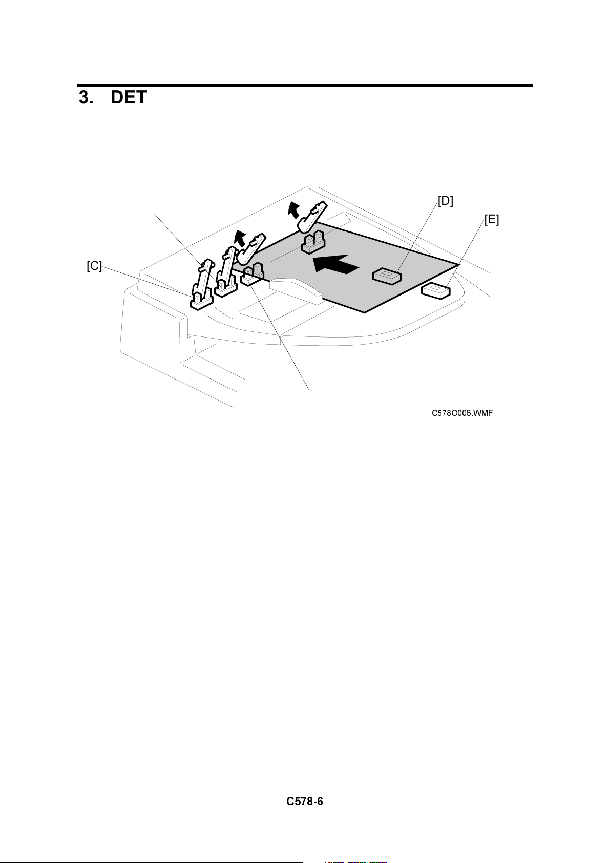
3.1 ORIGINAL SIZE DETECTION
[D]
[B]
[C]
[E]
[A]
C578O006.WMF
The DF has three width sensors (- 1 [A], - 2 [B], and - 3[C]) to detect the original
width and two original length sensors (-1 [D] and -2 [E]) to detect the original
length. The DF detects the original size through the combination of those five
sensors as shown in the table on the next page.
C578-6
Page 8

1 July, 1998 ORIGINAL SIZE DETECTION
Original
Width-1
A3 (297 x 420) ON ON ON ON ON
B4 (257 x 364) ON ON ON ON
A4 (Lengthwise)
(210 x 297)
A4 (297 x 210)
(Sideways)
B5 (182 x 257)
(Lengthwise)
B5 (257 x 182)
(Sideways)
A5 (148 x 210)
(Lengthwise)
A5 (210 x 148)
(Sideways)
11" x 17" (DLT) ON ON ON ON ON
11" x 15" ON ON ON ON ON
10" x 14" ON ON ON ON
8.5" x 14" (LG) ON ON ON
8.5" x 13" (F4) ON ON ON
8" x 13" (F) ON ON ON
8.5" x 11"
(Lengthwise)
8.5" x 11"
(Sideways)
10" x 8"
(Lengthwise)
5.5" x 8.5"
(Lengthwise)
(HLT)
5.5" x 8.5"
(Sideways) (HLT)
ON ON
ON ON ON
ON
ON ON
ON
ON ON
ON ON ON
ON ON
ON
Original
Width-2
Original
Width-3
Original
Length-1
Original
Length-2
ON: Paper present
Options
C578-7
Page 9

PICK-OFF AND SEPARATION MECHANISM 1 July, 1998
3.2 PICK-OFF AND SEPARATION MECHANISM
[F]
[B]
[D]
C578O008.WMF
[C]
[E]
C578O009.WMF
[A]
[B]
[F]
[G]
C578O010.WMF
When the Start key is pressed, the DF pick-up solenoid [A] turns on and the
originals are lifted up to the pick-up roller [B] by the entrance guide [C]. At the same
time, the DF feed clutch [D] turns on.
At 300 ms after this, the DF feed motor turns on. The original is fed to the paper
feed belt [E] from the top page. The pages are separated by the separation roller
[F] and the top sheet of the original is fed to the 1st transport roller [G]. The original
separation system uses the FRR system.
C578-8
Page 10

1 July, 1998 ORIGINAL TRANSPORT AND EXIT MECHANISM
3.3 ORIGINAL TRANSPORT AND EXIT MECHANISM
[A]
C578O011.WMF
[B]
[C]
[D]
When the leading edge of the original reaches the registration sensor [A], the DF
feed motor turns off. After a short time the DF feed motor turns on again. The
original is fed to the DF exposure glass [B] and it is scanned in this area.
The original is fed through to the 2nd transport roller [C] and fed out by the exit
roller [D].
The DF feed motor speed while feeding the original to the registration sensor is
47.5 mm/s. However, when the motor turns on again to feed the original to the
exposure glass, the speed depends on the selected reproduction ratio. At 100%, it
is 42.33 mm/s.
Options
C578-9
Page 11

OVERALL ELECTRICAL CIRCUIT 1 July, 1998
3.4 OVERALL ELECTRICAL CIRCUIT
I/O Board
C578O502.WMF
The DF pick-up solenoid and DF feed clutch are directly controlled by the CPU of
the main body through the DF drive board. The sensor signals are directly sent to
the main body through the DF interface board. The DF drive board has a driver for
the DF feed motor and its drive signal is sent from the main body.
When the DF connector is connected to the I/O board of the main body, the DF
connection signal to the main body is grounded. Then the main body detects that
the DF is connected.
C578-10
Page 12

1 July, 1998 ORIGINAL FEED UNIT REMOVAL
4. REPLACEMENT AND ADJUSTMENT
4.1 ORIGINAL FEED UNIT REMOVAL
[A]
[B]
1. Open the DF feed cover.
2. Push the original feed unit to the front [A].
3. Release the rear joint of the original feed unit [B].
4. Remove the original feed unit.
C578O015.WMF
Options
C578-11
Page 13

SEPARATION ROLLER REPLACEMENT 1 July, 1998
4.2 SEPARATION ROLLER REPLACEMENT
[A]
[C]
[B]
1. Remove the original feed unit.
2. Remove the support guide [A] (1 screw).
3. Remove the snap ring [B].
4. Replace the separation roller [C].
C578O016.WMF
C578-12
Page 14

1 July, 1998 PICK-UP ROLLER REPLACEMENT
4.3 PICK-UP ROLLER REPLACEMENT
[B]
[A]
[B]
[C]
1. Remove the original feed unit.
2. Remove the pick-up roller unit [A].
3. Remove the two snap rings [B].
4. Replace the pick-up roller [C].
C578O017.WMF
Options
C578-13
Page 15

FEED BELT REPLACEMENT 1 July, 1998
4.4 FEED BELT REPLACEMENT
[B]
[A]
[C]
[C]
[E]
[D]
C578O019.WMF
[H]
[G]
[F]
[G]
[E]
C578O018.WMF
1. Remove the original feed unit.
2. Remove the pick-up roller unit.
3. Remove the front bushing [A], spring [B], and washer [C] (1 E-ring).
4. Remove the original guide [D] (1 E-ring).
5. Release the idle roller holder [E] from the drive roller shaft.
6. Remove the idle roller [F], idle roller holder [E], and 2 springs [G].
7. Replace the feed belt [H].
C578-14
Page 16

1 July, 1998 ORIGINAL SET SENSOR AND WIDTH SENSOR REPLACEMENT
4.5 ORIGINAL SET SENSOR AND WIDTH SENSOR
REPLACEMENT
[A]
[D]
[E]
[B]
[C]
C578O020.WMF
1. Open the DF feed cover.
2. Remove the entrance guide [A] (3 screws).
3. Replace the following sensors.
Original Set Sensor [B]
Original Width Sensor 1 [C]
Original Width Sensor 2 [D]
Original Width Sensor 3 [E]
C578-15
Options
Page 17

DF COVER REMOVAL 1 July, 1998
4.6 DF COVER REMOVAL
[B]
[C]
[A]
1. Open the DF feed cover.
2. Remove the front cover [A] (3 screws).
3. Remove the original table [B] (1 screw, 1 connector).
4. Remove the rear cover [C] (5 screws).
C578O021.WMF
C578-16
Page 18

1 July, 1998DF FEED COVER OPEN , DF POSITION, AND APS START SENSOR
REPLACEMENT
4.7 DF FEED COVER OPEN , DF POSITION, AND APS
START SENSOR REPLACEMENT
[B]
[C]
[A]
1. Remove the rear cover.
2. Replace the following sensors.
DF Feed Cover Open Sensor [A].
DF Position Sensor [B].
APS Start Sensor [C].
C578O503.WMF
Options
C578-17
Page 19

ORIGINAL LENGTH SENSOR REPLACEMENT 1 July, 1998
4.8 ORIGINAL LENGTH SENSOR REPLACEMENT
[A]
[B]
[C]
1. Remove the original table.
2. Remove the original guide [A] (3 screws).
3. Replace the following sensors.
Original Length Sensor 1 [B]
Original Length Sensor 2 [C]
C578O023.WMF
C578-18
Page 20

1 July, 1998 DF FEED CLUTCH AND DF PICK-UP SOLENOID REPLACEMENT
4.9 DF FEED CLUTCH AND DF PICK-UP SOLENOID
REPLACEMENT
[A]
[B]
1. Remove the rear cover.
2. Replace the following clutch and solenoid.
DF Feed Clutch [A] (2 E-rings, 1 connector)
DF Pick-up Solenoid [B] (2 screws, 1 connector)
C578O504.WMF
C578-19
Options
Page 21

REGISTRATION SENSOR REPLACEMENT 1 July, 1998
4.10 REGISTRATION SENSOR REPLACEMENT
[B]
[A]
1. Remove the front cover.
2. Remove the original feed unit.
3. Remove the DF feed cover [A] (1 screw).
[C]
[D]
C578O024.WMF
4. Remove the transport guide [B] (2 screws).
5. Remove the original exposure guide [C] (1 screws).
6. Replace the registration sensor [D] (1 screw, 1 connector).
C578-20
 Loading...