

Page 1

DOCUMENT FEEDER
DF UNIT TYPE 50 (50-SHEET)
(C562)
Page 2
6
15 November 1995 OVERALL MACHINE INFORMATION
1.
OVERALL MACHINE INFORMATION
1.1 SPECIFICATIONS
Original Type: Sheet-feed
Original Paper Size: Maximum 307 mm x 432 mm (12.0" x 17.0")
Minimum 90 mm x 140 mm (3.6" x 5.5")
Original Weight: 40.7 g/m2 to 127.9 g/m2, 10.8 lb to 34 lb
ADF Original Capacity: 50 sheets (66 g/m2, 17.6 lb)
42 sheets (80 g/m2, 20 lb) or 4.2 mm, 0.15"
height
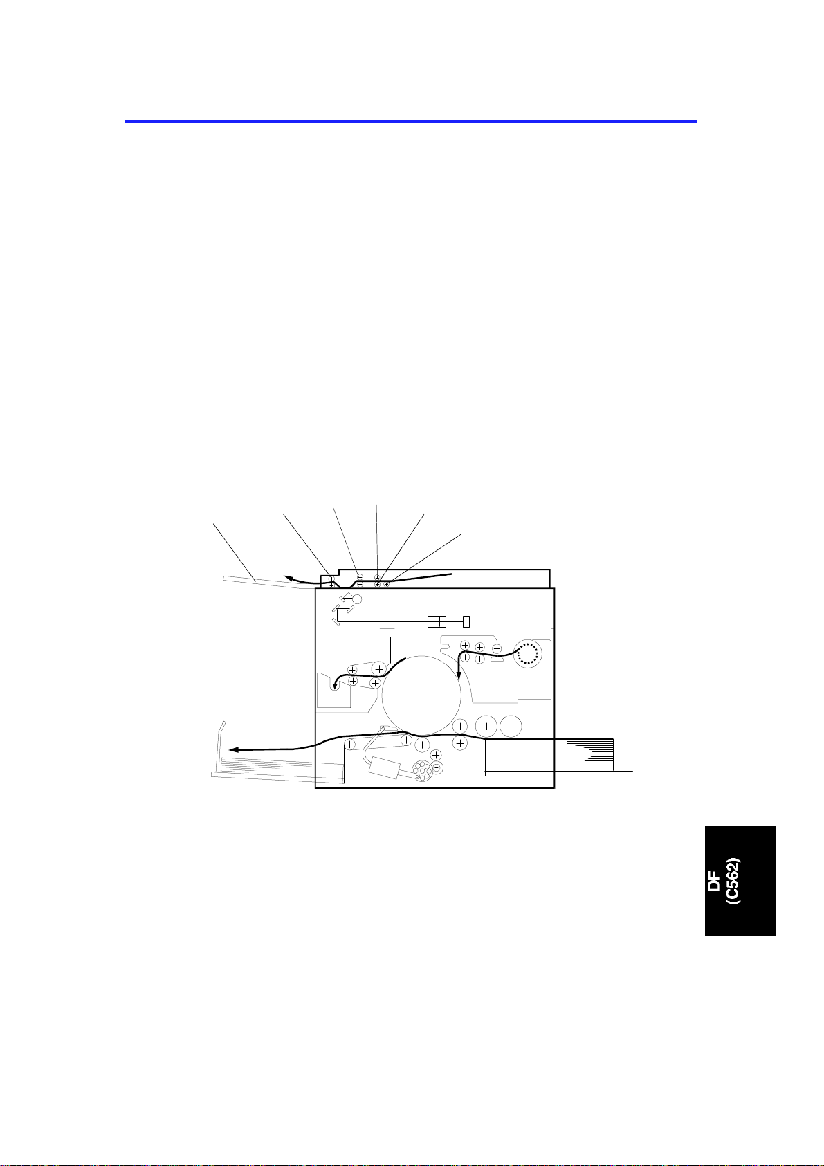
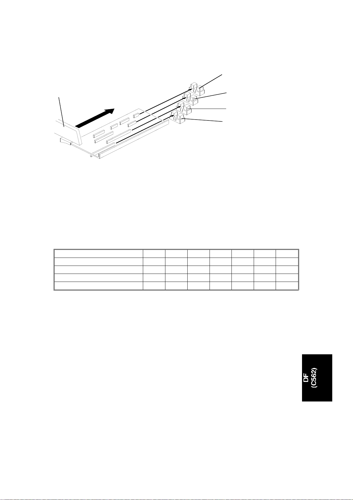
1.2 MECHANICAL COMPONENT LAYOUT
1
1. Original Exit Tray
2. 2nd Original Transport Roller
3. 1st Original Transport Roller
4. Separation Roller
5. Feed Roller
6. Pickup Roller
2
3
4
5
C562V500.wmf
1
Page 3
7
OVERALL MACHINE INFORMATION 15 November 1995
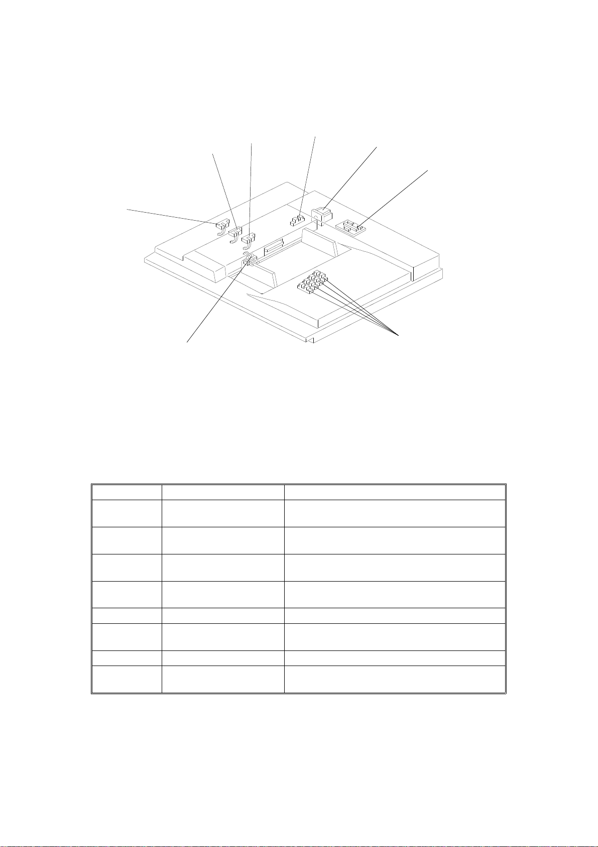
1.3 ELECTRICAL COMPONENT LAYOUT
3
2
4
5
1
8
C562V504.wmf
1. Original Exit Sensor 5. ADF Motor
2. Scan Line Sensor 6. ADF Interface Board
3. Original Registration Sensor 7. Original Width Sensor
4. ADF Cover Sensor 8. Original Set Sensor
6
COMPONENT DESCRIPTION
Index No. Name Function
1 Original Exit Sensor Informs the CPU when the original activates the
sensor. Also detects original misfeeds.
2 Scan Line Sensor Determines the timing for scanning. Also
detects original misfeeds.
3 Original Registration
Sensor
4 ADF Cover Sensor Informs the CPU when the ADF cover is
5 ADF Motor Drives the mechanisms in the ADF.
6 ADF Interface Board Controls the ADF in response to signals from
7 Original Width Sensor Informs the CPU of the original width.
8 Original Set Sensor Informs the CPU when an original is placed in
Determines the timing for the ADF motor to
start. Also detects original misfeeds.
opened.
the main body.
the ADF.
2
Page 4
[P]
15 November 1995 SECTIONAL DESCRIPTIONS
2.
SECTIONAL DESCRIPTIONS
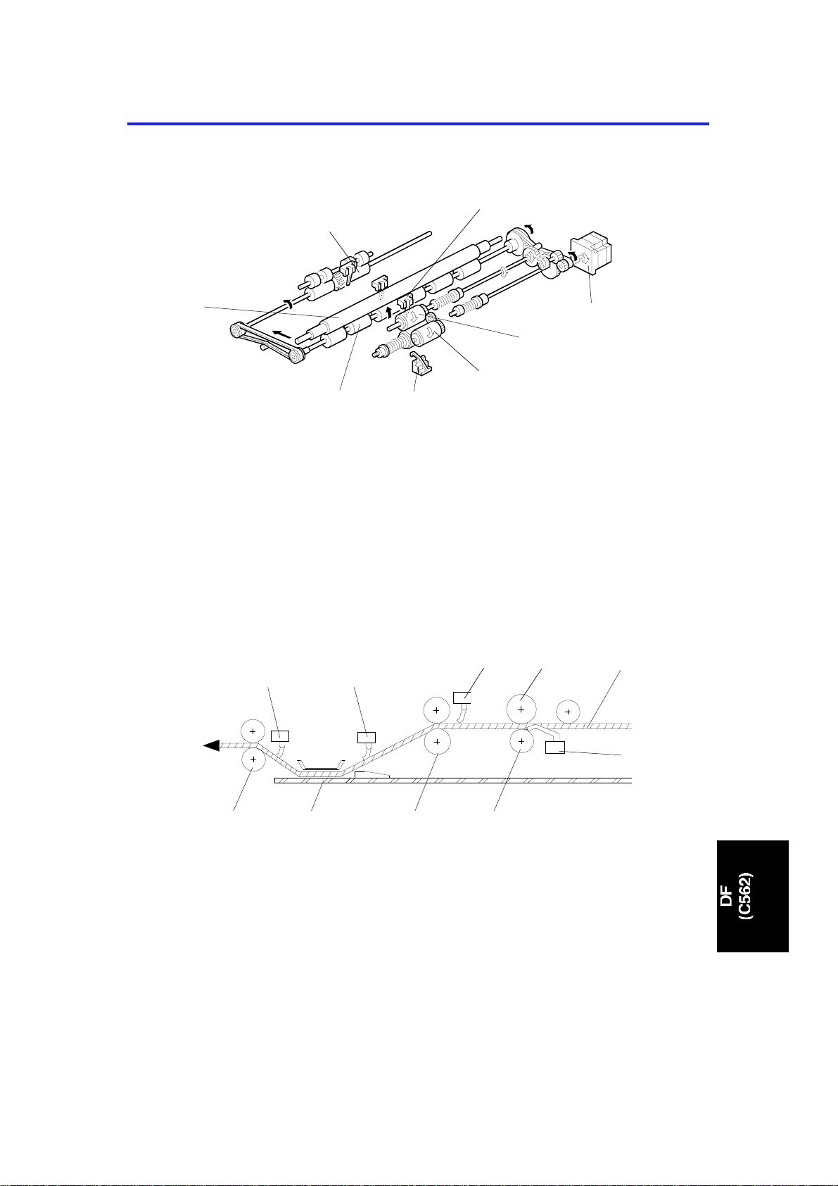
2.1 DRIVE MECHANISM
[F]
[H]
[G]: Original Set Sensor
[H]: 1st Original Transport Roller
The ADF motor [A] is a stepper motor. The ADF motor rota te s clockwise and
then counterclockwise to fee d th e original. When the Master Makin g key is
pressed, the ADF motor rotates clockwise to drive the pick up roller [B] an d
the feed roller [C] turns clockwise to feed the top page of the original. When
the original has been fed 14.5 mm after the original registra tio n sen sor [D]
was activated, the ADF motor starts to rotate counterclockwise. This drives
the lower 1st original transport roller [E ] and the lowe r origin al exit roller [F]
counterclockwise, feeding the original.
[N] [O]
[F]
[E]
[G]
[B]
[A]
[C]
C562D500.wmf
[J]
[R]
[M]
[I]: Original Set Sensor
[J]: Feed Roller
[K]: 1st Original Transport Roller
[L]: Exposure Glass
[M]: 2nd Original Transport Roller
[L]
[K]
3
[Q]
[N]: Original Exit Sensor
[O]: Scan Line Sensor
[P]: Original Registration Sensor
[Q]: Separation Roller
[R]: Original Paper Path
C562D501.wmf
[I]
Page 5
SECTIONAL DESCRIPTIONS 15 November 1995
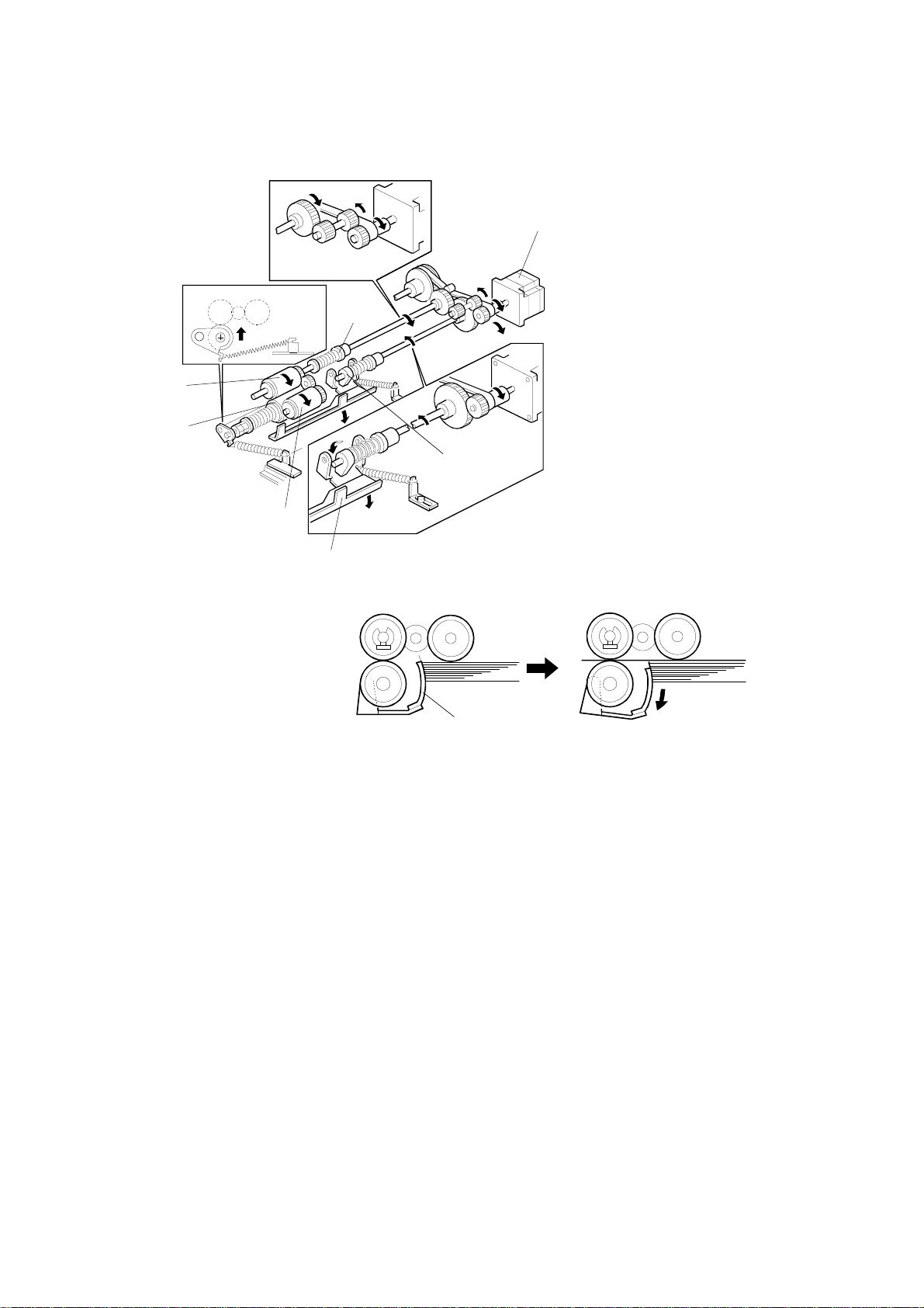
2.2 PAPER FEED AND SEPARATIO N
[G]
[B]
[F]
[E]
[D]
[A]
C562D502.wmf
[C]
[C]
C562D503.wmf
When the originals are placed on the ADF and the Master Making key is
pressed, the pickup roller [A] starts to rotate as it is lowered by the spring
clutch [B] to touch the top page of the document. The original shutter [C] is
lowered by the spring clut ch an d th e lever [D] when the ADF motor is turn ed
on. The separation roller [E] and the feed roller [ F] allo w only one page into
the scanner. The one-way clutch on the feed roller pre vents its backward
rotation when the ADF motor [G ] rot at es cou nt erclockwise.
The pick-up and the shu tter torque are adjustable by the length of the spring.
See Pick-up Torque Adjustmen t and Sh ut ter Torque Adjustment for det ails.
4
Page 6
15 November 1995 SECTIONAL DESCRIPTIONS
2.3 ORIGINAL SIZE DETECTION
[E]
[A]
[B]
[C]
[D]
[A]: Original Width Sensor-0
[B]: Original Width Sensor-1
[C]: Original Width Sensor-2
C562D504.wmf
[D]: Original Width Sensor-3
[E]: Front Original Guid e
There are 4 sensors (photointe rrupters) for detecting the original wid th . Whe n
the front original guide [E] is shifted to match th e orig inal width, the plate [F ]
moves with the guide. Eight actuators are installe d on the plat e, and
depending on the side guide position, the sensor status will be changed.
The following table shows the relationship between the paper size and the
sensor status.
Original Size A3 DLT B4 LT/LG A4 B5 A5
Original Size Sensor-0 O O O
Original Size Sensor-1 O O O O
Original Size Sensor-2 OOOO
Original Size Sensor-3 O O O
X= Non-blocked, O= Blocked
* : All of the above original sizes are for len gthwise feed.
2.4 ORIGINAL MISFEED DETE CTI ON
The machine indicate s an original misfeed in the followin g con ditions.
•
When the original registratio n sen sor do es not go ON within 3 seconds
after the ADF motor starts rotating (clockwise).
•
When the scan line sensor d oes n ot go ON with in 2. 5 seconds after the
original registration sensor is turned on.
•
When the original exit sensor doe s not go ON afte r t he scan line sensor is
turned on and the original has been fed 60 millimeters.
5
Page 7
SECTIONAL DESCRIPTIONS 15 November 1995
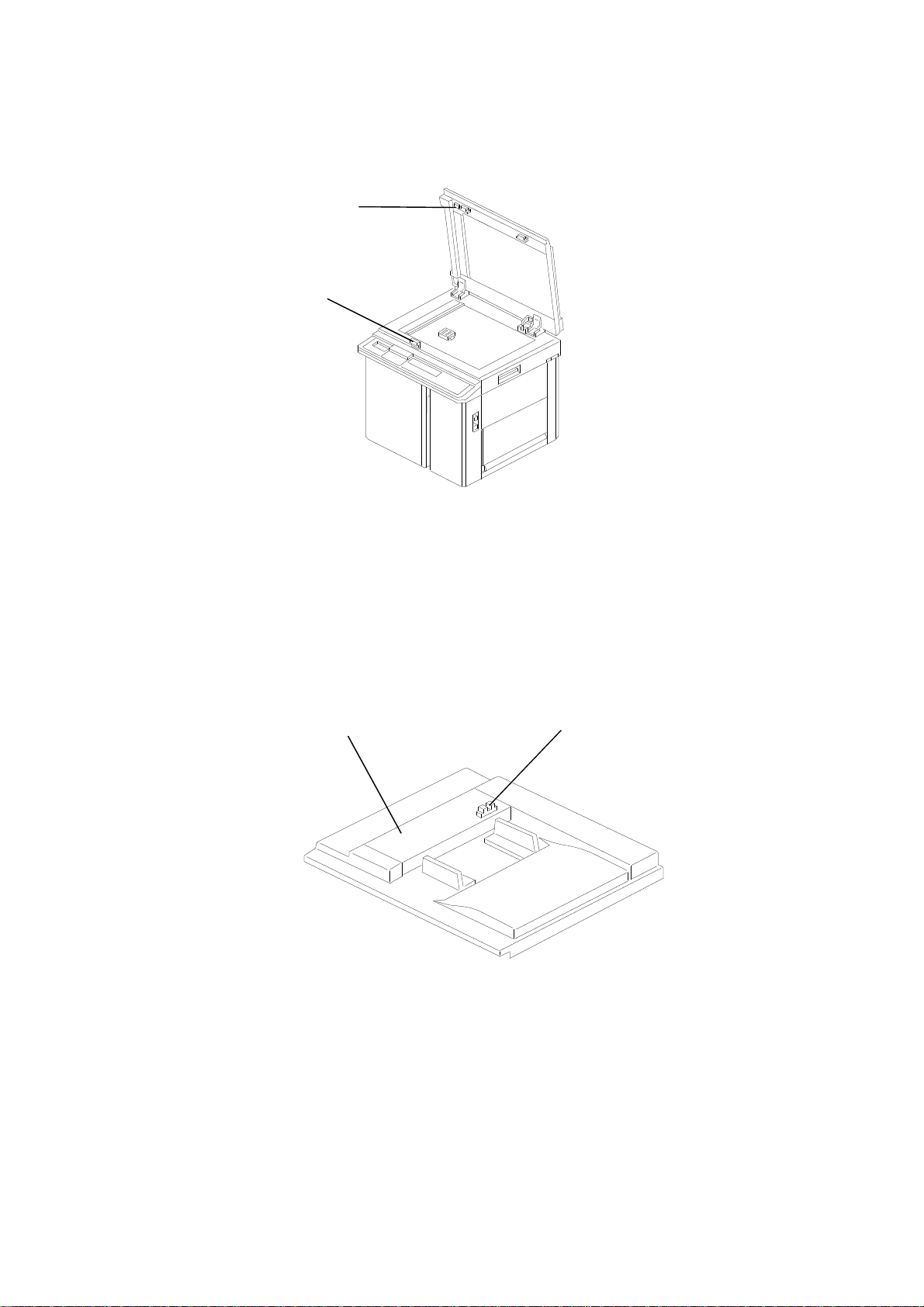
2.5 ADF OPEN/CLOSE DETECTION
[A]
[B]
C562D505.wmf
The ADF set sensor detects whet her t he ADF unit is opened or closed. This
sensor is a reed switch. A magnet mount ed on the ADF [A ] act ivat es th e ree d
switch [B]. When an original is pla ced in the ADF, if this re ed swit ch is not
activated, the Master Making key is disabled.
2.6 ADF POSITION DETECTIO N
[A]
[B]
C562D506.wmf
When the ADF cover [A] is opened, the plat en cover po sitio n sen sor [B ] is
deactivated. When this sensor is deactivated, the Master Making key is
disabled.
6
Page 8
15 November 1995 INSTALLATION PROCEDURE
3.
INSTALLATION PROCEDURE
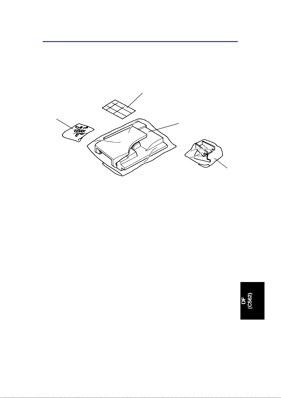
3.1 ACCESSORY CHECK
Decal Kit
Test Chart
Thumb Screws,
Screw and
Toothed Washer
Document Feeder Unit
Make sure that you have all the accesso ries liste d be low.
(1) Document Feeder Unit
(2) Bracket (2 pcs.)
(3) Screw and a Toothed Washer
(4) Thumb Screws (4 pcs.)
(5) Test Chart
(6) Installation Procedure
(7) Decal Kit
Brackets (2 pcs)
C562I500.img
7
Page 9
Pin
DF Connector
INSTALLATION PROCEDURE 15 November 1995
3.2 INSTALLATION PROCEDURE
[A]
[B]
[C]
C562I501.img
[D]
1. Turn off the main switch and unplug the power cord.
2. Open the Platen Cover, remove 4 screws [A] and remo ve the Platen
Cover.
3. Remove 3 screws [B] and remove the Upper Rear Cover.
4. Remove 2 screws [C] and remove the cover plate.
Pin
C562I502.img
5. Let the DF connector through the opening and mount the DF Unit as
shown in the diagram [D].
6. Secure the DF Unit by 4 screws that were removed in step 2.
8
Page 10

15 November 1995 INSTALLATION PROCEDURE
[C]
[A]
[B]
C562I503.img
[D]
7. Close the DF and connect the connector to the scanner connector [A].
C562I504.img
8. Secure the wire [B] by the screw and the washer in th e acce ssory.
9. Secure the DF Harness Bracket by 2 screws [C].
10. Replace the Upper Rear Cover by 3 screws.
11. Secure the machine by placing 2 brackets [D] on the back of the tab le
using 4 thumb screws in the accessory.
CAUTION
I
The brackets must be attached to the back of the table. This is to prevent the machine from falling over when the ADF is opened.
Also, make sure that the machine is secur ed to the table.
9
Page 11

INSTALLATION PROCEDURE 15 November 1995
When C562 is installed on the C222 or C223 model, change the SP mode
setting as follows: (The follo wing procedure is not required for C550. )
For the C222 model:
12. Press the Clear Modes, Clear, Combine 2 Origin als and Ente r (#) keys to
access the SP mode.
13. Change the setting of SP2-50 from OFF to ON. Then press th e En ter Key
to store the setting.
14. Leave the SP mode.
For the C223 model:
12. Press the Clear modes, Clear, Multi Copy and Enter(#) keys to access
SP mode.
13. Change the setting of SP8 from 0 to 1.
Then press the Enter key to store the setting.
14. Leave the SP mode.
When you install the optional ADF, do the following adju stme nt s.
• ADF height adjustment.
• Image center adju stment.
• Image scan magnificatio n ad just men t.
10
Page 12

15 November 1995 SERVICE TABLES
4.
SERVICE TABLES
4.1 USER’S MAINTENANCE
Advise the customer to clean each item regularly. Clean the followin g ite ms
at every EM call if necessary.
Cleaning Point Cleaner
Original Feed Rollers Cloth, soap, and water
4.2 PERIODIC INSPECTION
Inspect the following every 6 months.
Item Standard Procedure
Pick-up Roller
Feed Roller
Separation Roller
Wipe off paper powder using a cloth moistened with water.
11
Page 13

[E]
REPLACEMENT AND ADJUSTMENT 15 November 1995
5.
REPLACEMENT AND ADJUSTMENT
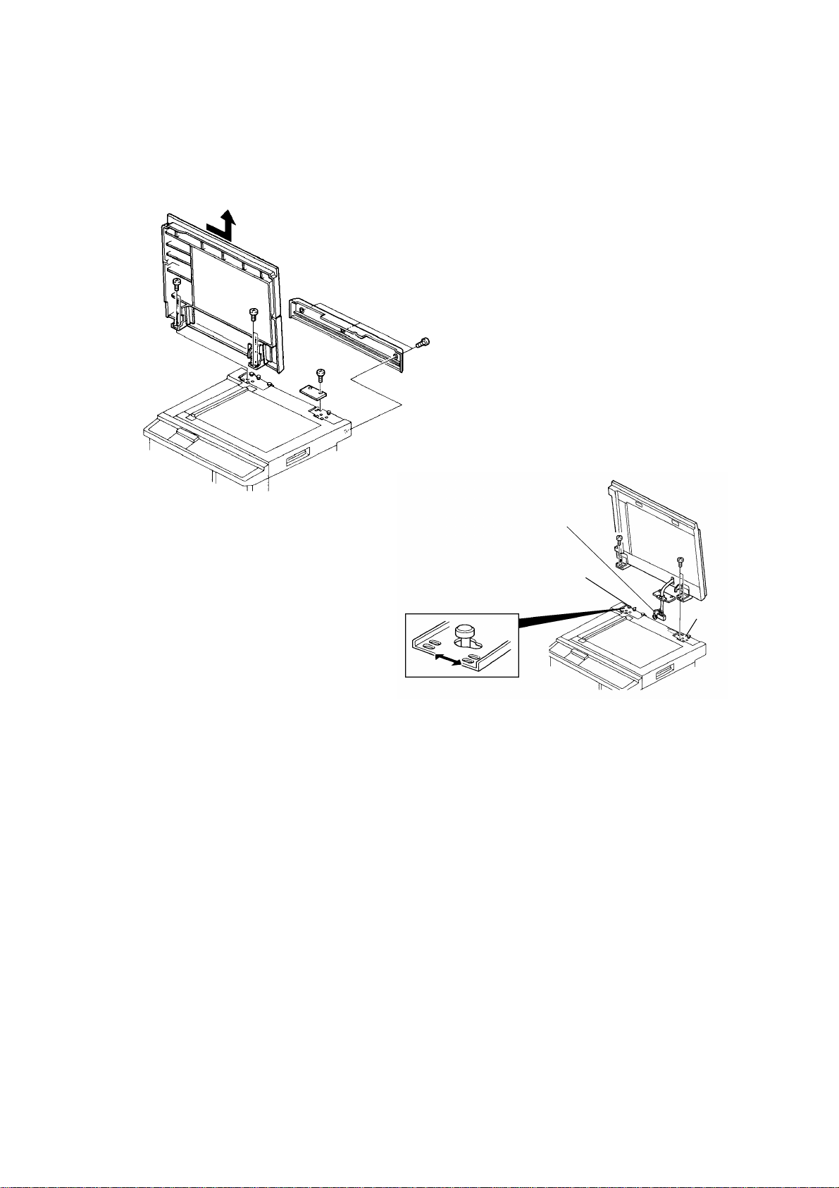
5.1 ADF UNIT REMOVAL
[D]
[A]
[C]
[B]
1. Remove the upper rear cover [A] of the main frame (3 screws).
2. Disconnect the connector [B], and remove the screw [C] that holds the
ground wire.
3. Remove the DF harness bracket [D] (2 screws).
4. Open the ADF unit and remove the four screws [E] that hold the ADF unit
hinge.
C562R501.img
C562R500.img
5. Slide the unit to the right and remove the ADF unit from the machine.
NOTE: When you reinstall the ADF unit, perform the followin g adjust men ts:
ADF Height Adjustment
Image Center Adjustment
Image Scan Magnification Adjustment
12
Page 14

15 November 1995 REPLACEMENT AND ADJUSTMENT
5.2 ADF COVER REMOVAL
[A]
[A]
[A]
C562R502.wmf
[C]
1. Remove the screws [A] securing the ADF cover (8 screws).
2. Disconnect the original size detector harness [B].
3. Remove the harness protector [C] (2 screws).
[B]
C562R503.wmf
13
Page 15

[C]
REPLACEMENT AND ADJUSTMENT 15 November 1995
5.3 ADF UPPER UNIT REMOVAL
[E]
[D]
[B]
[A]
[B]
C562R527.wmf
1. Remove the ADF cover (see section 5-2).
2. Open the ADF unit [A] and remove two stopper screws [B].
3. Remove the ground wire [C] (1 screw, 1 toothed washer).
4. Disconnect the connector [D].
5. Remove the collar [E] (1 Allen screw).
6. Remove the ADF upper unit [A] (2 bushings, 1 E-ring).
14
Page 16

[A]
15 November 1995 REPLACEMENT AND ADJUSTMENT
5.4 SEPARATION ROLLER REMOV AL
[B]
[D]
[A]
[C]
C562R505.wmf
1. Remove the ADF cover (see section 5-2).
2. Remove the two stopper screws [A] and fully open th e ADF up pe r unit .
3. Remove the lower guide plate [B] (2 screws).
4. Remove the screw [C] that holds the separat ion ro ller [D] , an d remo ve the
separation roller.
NOTE: When replacing the separatio n rolle r, pe rfo rm the sepa rat ion torque
adjustment (see section 5-1 5).
15
Page 17

REPLACEMENT AND ADJUSTMENT 15 November 1995
5.5 ORIGINAL SET SENSOR RE MOV AL
[B]
[A]
[D]
C560R506.wmf
[A]
[C]
1. Remove the ADF cover (see section 5-2).
2. Remove the two stopper screws [A] and fully open th e ADF up pe r unit .
3. Remove the lower guide plate [B] (2 screws).
4. Remove the sensor bracket [C] (2 screws) and remove the original set
sensor [D].
16
Page 18

[A]
15 November 1995 REPLACEMENT AND ADJUSTMENT
5.6 ORIGINAL REGISTRATI ON S ENS OR RE MOV AL
[B]
C562R507.wmf
1. Remove the ADF cover (see section 5-2).
2. Remove the two stopper screws and fully open the ADF upper unit (see
the previous page).
3. Remove the sensor bracket [A] (2 screws) and remove th e orig inal
registration sensor [B].
17
Page 19

REPLACEMENT AND ADJUSTMENT 15 November 1995
5.7 PICK-UP ROLLER AND FEED ROLLER REMO VAL
[C]
[D]
[A]
[B]
[E]
C562R522.wmf
1. Remove the ADF cover (see section 5-2).
2. Remove the two stopper screws and fully open the ADF upper unit (see
section 5-5).
3. Remove the E-ring [A] and remove the pick-up roller drive gear [B].
4. Remove the upper guide plate [C].
5. Remove the pick-up roller [D].
6. Remove the clip and remove the feed roller [E].
18
Page 20

15 November 1995 REPLACEMENT AND ADJUSTMENT
5.8 SCAN LINE SENSOR REMOV AL
[B]
[A]
C560R508.wmf
1. Remove the ADF upper unit (see section 5-3).
2. Remove the sensor bracket [A] (1 screw).
3. Remove the scan line sensor [B] (1 connector).
5.9 ORIGINAL EXIT SENSOR REMOV AL
[B]
[A]
1. Remove the ADF unit (see section 5-1).
C562R609.wmf
2. Remove the sensor bracket [A] (1 screw).
3. Remove the original exit sensor [B] (1 connector).
19
Page 21

REPLACEMENT AND ADJUSTMENT 15 November 1995
5.10 ADF COVER SENSOR REMOV AL
[C]
[B]
[A]
[C]
C562R523.wmf
C562R524.wmf
1. Remove the ADF cover (see section 5-2).
2. Remove the ADF upper unit (see section 5-3).
3. Remove the lower guide plate (2 screws).
4. Remove the transport guide plate [A] (4 screws).
5. Open the ADF unit and peel away the platen sheet [B ] to access the ADF
cover sensor [C].
6. Remove the ADF cover sensor.
20
Page 22

15 November 1995 REPLACEMENT AND ADJUSTMENT
5.11 TRANSPORT ROLLER REMOVAL
[B]
[A]
[E]
C562R525.wmf
[A]
[C]
1. Remove the ADF cover (see section 5-2).
2. Remove the ADF upper unit (see section 5-3).
[D]
C562R526.wmf
3. Loosen the screws [A] that hold the front and re ar belt tension brackets.
4. Remove the transport guide plate [B] (4 screws).
5. Remove the front pulley [C] (1 screw).
6. Remove the rear pulley [D] (1 clip).
7. Remove the transport roller [E] (2 bushings).
NOTE: A one-way clutch is installed in the rear pulley [D]. Install the pulley in
the proper direction.
21
Page 23

REPLACEMENT AND ADJUSTMENT 15 November 1995
5.12 ADF MOTOR REMOVAL
[A]
[D]
[E]
[B]
[C]
C562R514.wmf
1. Remove the ADF cover (see section 5-2).
2. Loosen the screw [A] securing the belt tension bracket.
3. Disconnect the motor harness [B].
4. Remove the motor bracket [C] (2 screws, 1 timing belt).
5. Remove the ground wire [D] (1 screw).
6. Remove the ADF motor [E] (2 screws).
NOTE: 1. When reinstalling th e motor bracket, push down the bra cket as
shown, then tighten the fo ur screws.
2. After reinstalling the timing belt, make sure that you tight en the
screw [A].
22
Page 24

[A]
15 November 1995 REPLACEMENT AND ADJUSTMENT
5.13 PICK-UP TORQUE ADJUSTMENT
[C]
[A]
[B]
25 ± 0.3mm
C562R515.wmf
Purpose: To ensure that the originals are picked-up properly.
Adjustment Standard: 25.0 ± 0.3 mm
[D]
1. Remove the ADF cover (see section 5-2).
2. Remove the two stopper screws [A] and fully open th e ADF up pe r unit .
3. Remove the gear [B] (1 E-ring) and remove the upper guide plate [C] (4
screws).
4. Confirm that the length of the spring on the separation roller shaf t is 25. 0
± 0.3 mm.
5. If it is not within the specified range, loosen the Allen screw [D] and adju st
the collar position.
NOTE: After this adjustmen t, ch eck if th e separation roller shaft rot ates
smoothly.
23
Page 25

[A]
REPLACEMENT AND ADJUSTMENT 15 November 1995
5.14 SHUTTER TORQUE ADJUSTMENT
[B]
[C]
[A]
20.5 ± 0.3mm
C562R516.wmf
Purpose: To ensure that the original shutter functions prope rly.
Adjustment Standard: 20.5 ± 0.3 mm
1. Remove the ADF cover (see section 5-2).
2. Remove the two stopper screws [A] and fully open th e ADF up pe r unit .
3. Remove the lower guide plate [B] (2 screws).
4. Confirm that the spring length is 20.5 ± 0.3 mm.
5. If the value is not within the specified rang e, loosen the screw [C] and
adjust the spring length by sliding the collar.
If the original is not transported after moving the stop pe r, extend the
spring length.
If original multi-feed occurs, shorten the spring length.
24
Page 26

[A]
[C]
15 November 1995 REPLACEMENT AND ADJUSTMENT
5.15 SEPARATION ROLLER TORQ UE ADJ USTME NT
[B]
[A]
19 ± 0.3mm
C562R517.wmf
Purpose: To ensure that the top original is properly separated from the
original stack.
Adjustment Standard: 19.0 ± 0.3 mm
1. Remove the ADF cover (see section 5-2).
2. Remove the two stopper screws [A] and fully open th e ADF up pe r unit .
3. Remove the lower guide plate [B] (2 screws).
4. Check the separation torque sprin g length.
5. If the length is not within the specified ra ng e, turn the hexagon bolts [C] to
adjust the separation roller torque.
25
Page 27

REPLACEMENT AND ADJUSTMENT 15 November 1995
5.16 ORIGINAL SKEW ADJUSTMENT
[A] [B]
C562R518.wmf
Purpose: To correct original skew.
1. Open the ADF unit.
2. Loosen the screw [A] and move the adjustmen t pla tes to correct the skew.
3. After adjusting the skew, tighten the plate properly.
26
Page 28

[A]
[C]
A
15 November 1995 REPLACEMENT AND ADJUSTMENT
5.17 ORIGINAL SEPARATIO N PRE SS URE ADJ USTMENT
[B]
B
[A]
[D]
C562R519.wmf
Purpose: To ensure that the top original is properly separated from the
original stack.
1. Remove the ADF cover (see section 5-2).
2. Remove the two stopper screws [A] and fully open th e ADF up pe r unit .
3. Remove the lower guide plate [B] (2 screws).
4. Loosen the screw [C] securing the pressure adjusting lever [D] the n move
the lever to change th e pre ssure.
Original non-feed: Move the lever to wards "A" (to decease the pressure ).
Original multi-feed: Move the lever towards "B" (to increase th e pre ssure).
After adjusting th e pressure, tighten the screw [ C].
27
Page 29

REPLACEMENT AND ADJUSTMENT 15 November 1995
5.18 ADF HEIGHT ADJUSTMENT
[B]
[B]
[A]
C562R520.wmf
[C]
[C]
Purpose: To ensure that the image can be scanned prope rly.
Adjustment Standard: Less than 0.5 mm
1. Slide the scanner unit to the left [A].
[D]
[E]
C562R521.wmf
2. Remove two positioning pins (white) [B] under the scanner unit. Then,
attach them to the ADF as shown in the diag ram.
3. Close the ADF and check that the gap [C] between the positioning pins
and the scanner upper cove r is less th an 0.5 mm, using a thickness
gauge.
4. If not, adjust the ADF height as follows.
4-1. Remove the upper rear cover (se e sect ion 5-1 of the main frame’s
manual).
4-2. Loosen the nut [D] and adjust th e heigh t by tu rnin g th e kno b screw
[E]. Then, tighten the nut.
5. After adjusting the ADF height position, put the positioning pins back in
their previous position (u nder the scanner unit).
28
Page 30

15 November 1995 REPLACEMENT AND ADJUSTMENT
5.19 IMAGE SCAN MAGNIFICATION ADJUSTMENT
Purpose: To correct the sub-scan magnifica tio n.
Adjustment Standard: 100 ± 0.5% in full size mode.
1. Using a test chart, make a print in ADF mode.
2. Check if the sub-scan magnification is within the specif ied ra nge.
3. If it is out of the specified range, adjust the sub-sca n magnification using
SP36.
5.20 IMAGE CENTER ADJUSTMENT (SIDE-TO-S IDE)
Purpose: To correct the cente r p osit ion of the printed image.
Adjustment Standard: Less than 1 mm
NOTE: Before adjusting the image cent er po sitio n in ADF mod e, adju st th e
image center for platen mode.
1. Using a test chart, make a print using both ADF mo de and plat en mo de.
2. Compare both copies and check that t he diff erence between the two
copies is within 1 mm.
3. If the difference is not within the specif ied range, adjust the imag e cen ter
using SP39-1.
5.21 SCANNER LEADING EDGE REGISTRATI ON
ADJUSTMENT
Purpose: To adjust the vertical image posit ion of the prin ts with that of the
original.
Adjustment Standard: The scannin g starts at 5 mm after the leading edg e.
NOTE: When performing this adjustmen t, set th e prin t spe ed and ima ge
position to the standard position.
1. Using a test chart, make a print in ADF mode.
2. Check the scanner start position and adjust the scanner leading edge
registration using SP 38 .
29
 Loading...