

Page 1

DOCUMENT FEEDER (A628)
Page 2

1 August 1996 SPECIFICATIONS
1. SPECIFICATIONS
Original Size: Standard Size A3 to A5
Non-standard Size
Max. width 297 mm
Min. width 105 mm
Max. length 1260 mm
Min. length 128 mm
Original Weight : 50 g to 90 g
Table Capacity : 30 sheets (70 kg)
Original Standard Position: Rear left corner
Separation: FRR
Original Transport: Roller transport
Original Feed Order: From top original
Reproduction Range: 37 to 150%
Power Source: 24 & 5 Vdc from the copier
Power Consumption: 25 W
Dimensions (W x D x H): 550 x 470 x 120 mm
Weight: 9 kg
A628-1
Page 3
COMPONENT LAYOUT 1 August 1996
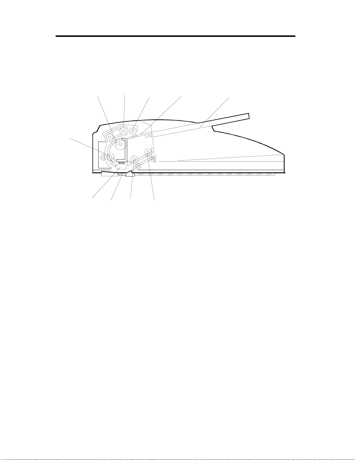
2. COMPONENT LAYOUT
2.1 MECHANICAL COMPONENT LAYOUT
1
10
9
87
1. Separation Roller
2. Paper Feed Belt
23
6
4
5
6. Original Exit Roller
7. 2nd Transport Roller
A628O005.wmf
3. Pick-up Roller
4. Original Entrance Guide
5. Original Table
8. DF Exposure Glass
9. Original Exposure Guide
10. 1st Transport Roller
A628-2
Page 4
1 August 1996 COMPONENT LAYOUT
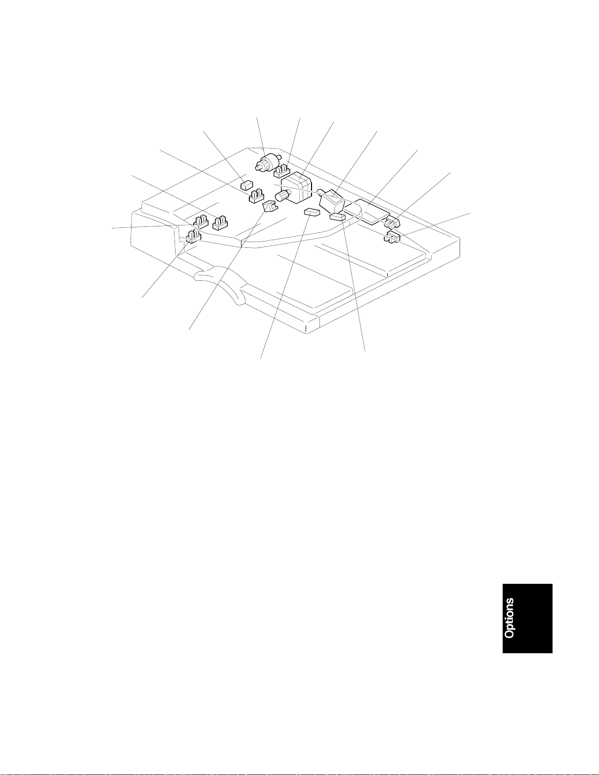
2.2 ELECTRICAL COMPONENT LAYOUT
12
13
11
14
10
15
1
2
3
4
5
6
7
9
8
A628O003.wmf
1. DF Feed Clutch
2. Feed Cover Open Sensor
3. DF Feed Motor
4. DF Pick-up Solenoid
5. DF Drive PCB
6. DF Position Sensor
7. APS Start Sensor
8. Original Length Sensor 2
9. Original Length Sensor 1
10. Stamper Solenoid
11. Original Width Sensor 3
12. Original Width Sensor 2
13. Original Width Sensor 1
14. Original Set Sensor
15. Registration Sensor
A628-3
Page 5

COMPONENT LAYOUT 1 August 1996
2.3 ELECTRICAL COMPONENT DESCRIPTION
Symbol Name Function Index
No.
Motors
S1 DF Feed Drives all the rollers. 3
Sensors
S1 APS Start Informs the CPU when the DF is opened and
closed (for platen mode) so tha t ori gi nal size
sensors in the copi er can check the or i gi nal size.
S2 DF Position Detects whether the DF is lifted or not. 6
S3 Registration Detects the leadi ng edge of the origi nal to turn off
the transport mo t or , detects the original exposure
timing, and ch ecks for original m i sf eeds.
S4 Feed Cover Open
Sensor
S5 Original Wi dt h - 1 Detects the original width 13
S6 Original Wi dt h - 2 Detects the original width 12
S7 Original Wi dt h - 3 Detects the original width 11
S8 Original Le ngt h - 1 Detects the original length. 9
S9 Original Le ngt h - 2 Detects the original length. 8
S10 Original Set Detects if an origi nal is on the feed tabl e. 14
Detects whether the feed-in cov er is opened or
not.
7
5
2
Solenoids
SOL1 DF Pick-up Controls the up-down movement of the origina l
table.
SOL2 Stamper Energizes the stamper to mark on the original. 10
Clutches
MC1 DF Feed Transfers tr ansport motor dri ve to the pick-up
roller and feed belt.
PCBs
PCB1 DF D rive In terfaces the sensor signals with t he copier, and
transfers the magnetic clutch, solenoid and motor
drive signals from the copier.
4
1
5
A628-4
Page 6
1 August 1996 COMPONENT LAYOUT
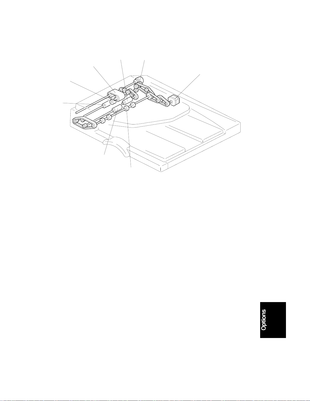
2.4 DRIVE LAYOUT
81
7
2
6
5
4
1. DF Feed Clutch
2. DF Feed Motor
3. Exit Roller
4. 2nd Transport Roller
3
A628O004.wmf
5. 1st Transport Roller
6. Separation Roller
7. Original Feed Belt
8. Pick-up Roller
A628-5
Page 7
DETAILED DESCRIPTIONS 1 August 1996
3. DETAILED DESCRIPTIONS
3.1 ORIGINAL SIZE DETECTION
[D]
[E]
[C]
[B]
A628O006.wmf
[A]
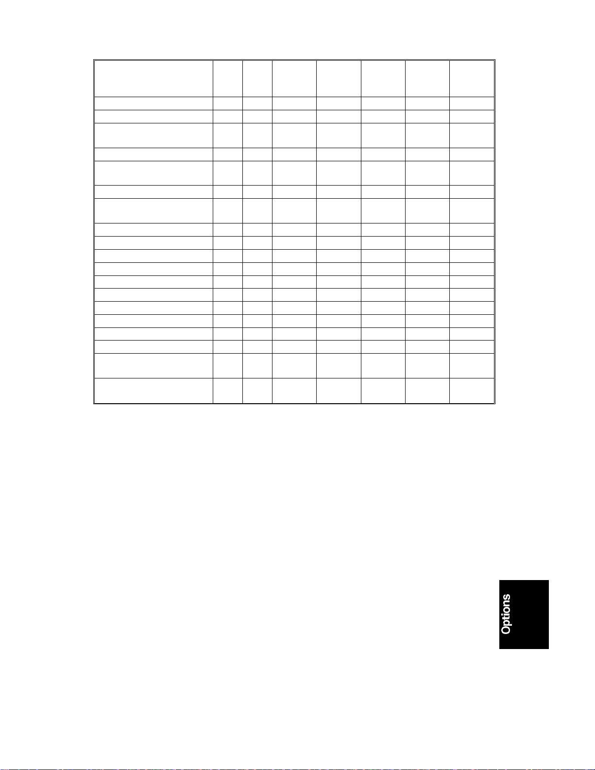
The DF has three width sensors (- 1 [A], - 2 [B], and - 3[C]) to detect the
original width and two original length sensors (-1 [D] and -2 [E]) to detect the
original length. The DF detects the original size through the combination of
those five sensors as shown in the table on the next page.
When using an original of a non-standard size, the user needs to input the
original length at the operation panel.
A628-6
Page 8
1 August 1996 DETAILED DESCRIPTIONS
A3 (297 x 420)
B4 (257 x 364)
A4 (Lengthwise)
(210 x 297)
A4 (297 x 210) (Si dew ays)
B5 (182 x 257)
(Lengthwis e)
B5 (257 x 182) (Si dew ays)
A5 (148 x 210)
(Lengthwis e)
A5 (210 x 148) (Si dew ays)
11" x 17" (DLT)
11" x 15"
10" x 14"
8.5" x 14" (LG)
8.5" x 13" (F4)
8" x 13" (F)
8.5" x 11" (Lengt hwi se)
8.5" x 11" (Sideways)
10" x 8" (Lengthwi se)
5.5" x 8.5" (Len gt hw ise)
(HLT)
5.5" x 8.5" (Sidew ays)
(HLT)
NA EU Original
Width-1
7m
7m
7m
7m
7m
7m
77
7m
m7
m7
m7
m7
7m
mm
m7
m7
m7
m7
m7
ON ON ON ON ON
ON ON – ON ON
ON – – ON –
ON ON ON – –
–––ON–
ON ON – – –
–––––
ON––––
ON ON ON ON ON
ON ON ON ON ON
ON ON – ON ON
ON – – ON ON
ON – – ON ON
ON – – ON ON
ON – – ON –
ON ON ON – –
ON – – ON –
–––––
ON––––
Original
Width-2
Original
Width-3
Original
Length-1
Original
Length-2
Key
7
: No, m: Yes
ON: Paper present
A628-7
Page 9
DETAILED DESCRIPTIONS 1 August 1996
3.2 PICK-OFF AND SEPARATION MECHANISM
[F]
[D]
[B]
[C]
A628O008.wmf
[A]
[E]
[B]
[F]
A628O009.wmf
[G]
A628O010.wmf
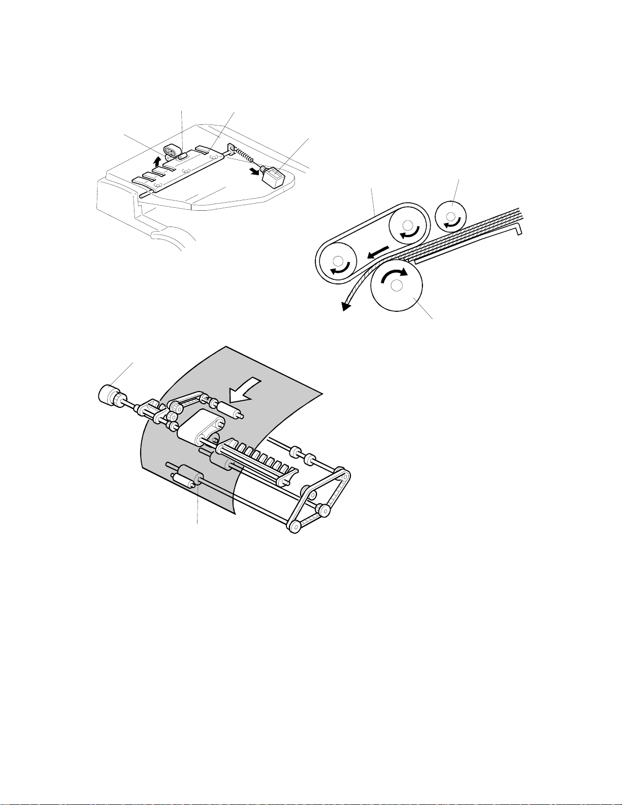
When the print key is pressed, the DF pick-up solenoid [A] turns on and the
originals are lifted up to the pick-up roller [B] by the entrance guide [C]. At the
same time, the DF feed clutch [D] turns on.
At 300 ms after this, the DF feed motor turns on. The original is fed to the
paper feed belt [E] from the top page. The pages are separated by the
separation roller [F] and the top sheet of the original is fed to the 1st transport
roller [G]. The original separation system uses the FRR system.
A628-8
Page 10
1 August 1996 DETAILED DESCRIPTIONS
3.3 ORIGINAL TRANSPORT AND EXIT MECHANISM
[D]
[A]
[B]
[C]
A628O011.wmf
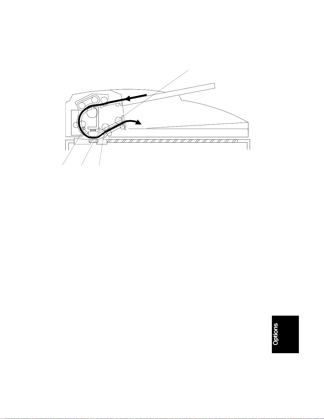
When the leading edge of the original reaches the registration sensor [A], the
DF feed motor turns off. After a short time the DF feed motor turns on again.
The original is fed to the DF exposure glass [B] and it is scanned in this area.
The original is fed through to the 2nd transport roller [C] and fed out by the
exit roller [D].
The DF feed motor speed while feeding the original to the registration sensor
is 47.5 mm/s. However, when the motor turns on again to feed the original to
the exposure glass, the speed depends on the selected reproduction ratio. At
100%, it is 90 mm/s.
A628-9
Page 11

DETAILED DESCRIPTIONS 1 August 1996
3.4 STAMP
[C]
[A]
[B]
A628O505.wmf
This function is only for fax mode.
There is a stamp [A] between the 2nd transport roller [B] and the exit roller
[C], and its solenoid is controlled by the copier directly.
When the original reaches the stamp position, the DF feed motor stops. At
300 milliseconds after stopping the DF feed motor, the stamper solenoid
turns on if the page was sent successfully (immediate transmission) or stored
successfully (memory transmission). After stamping, the DF feed motor starts
again for feeding out the document, and its speed is about 1.3 times the
normal speed.
The stamping position on the original can be changed by adjusting SP6-010.
A628-10
Page 12

1 August 1996 DETAILED DESCRIPTIONS
3.5 TIMING CHARTS
3.5.1 A4 Lengthwise
5000 pulses
935 pulses
JAM2
5899 pulses
935 pulses
300 ms
1173 pulses
1173 pulse
935 pulse
5899 pulses
935 pulses
5899 pulses
935 pulses
935 pulses
JAM3
JAM2
JAM3
JAM2
JAM1
(1s)
JAM1: The 1st original dose not reach the registration sensor (after 6413 pulses).
JAM2: The original remains at the registration sensor (after 8259 pulses).
JAM3: The 2nd or a later original does not reach the registration sensor (after 5596 pulses).
F Gate: Laser scan start signal.
DF Feed Motor
DF Pick-up
Solenoid
DF Feed Clutch
Original Set
Sensor
Original Width
Sensor
Registration
A628-11
Sensor
(F Gate)
(Jam Check)
A628O500.wmf
Page 13

DETAILED DESCRIPTIONS 1 August 1996
3.5.2 A4 Sideways (Stamper Mode)
A628-12
A628O501.wmf
Page 14

1 August 1996 DETAILED DESCRIPTIONS
3.6 OVERALL ELECTRICAL CIRCUIT
A628O502.wmf
The DF pick-up solenoid, stamper solenoid and DF feed clutch are directly
controlled by the copier through the DF drive board. The sensor signals are
directly sent to the copier through the DF interface board. The DF drive board
has a driver for the DF feed motor and its drive signal is sent from the copier.
When the DF connector is connected to the copier IOCSS board, the DF
connection signal to the copier is grounded. Then the copier detects that the
DF is connected.
A628-13
Page 15

REPLACEMENT AND ADJUSTMENT 1 August 1996
4. REPLACEMENT AND ADJUSTMENT
4.1 ORIGINAL FEED UNIT REMOVAL
[A]
[B]
1. Open the DF feed cover.
2. Push the original feed unit to the front [A].
3. Release the rear joint of the original feed unit [B].
4. Remove the original feed unit.
A628O015.wmf
A628-14
Page 16

1 August 1996 REPLACEMENT AND ADJUSTMENT
4.2 SEPARATION ROLLER REPLACEMENT
[A]
[C]
[B]
1. Remove the original feed unit.
2. Remove the support guide [A] (1 screw).
3. Remove the snap ring [B].
4. Replace the separation roller [C].
A628O016.wmf
A628-15
Page 17

REPLACEMENT AND ADJUSTMENT 1 August 1996
4.3 PICK-UP ROLLER REPLACEMENT
[B]
[A]
[C]
[B]
1. Remove the original feed unit.
2. Remove the pick-up roller unit [A].
3. Remove the two snap rings [B].
4. Replace the pick-up roller [C].
A628O017.wmf
A628-16
Page 18

1 August 1996 REPLACEMENT AND ADJUSTMENT
4.4 FEED BELT REPLACEMENT
[D]
[C]
[B]
[A]
[E]
1. Remove the original feed unit.
2. Remove the pick-up roller unit.
A628O019.wmf
[G]
[F]
[G]
[E]
[H]
A628o018.wmf
3. Remove the front bushing [A], spring [B], and washer [C] (1 E-ring).
4. Remove the original guide [D] (1 E-ring).
5. Release the idle roller holder [E] from the drive roller shaft.
6. Remove the idle roller [F], idle roller holder [E], and 2 springs [G].
7. Replace the feed belt [H].
A628-17
Page 19

REPLACEMENT AND ADJUSTMENT 1 August 1996
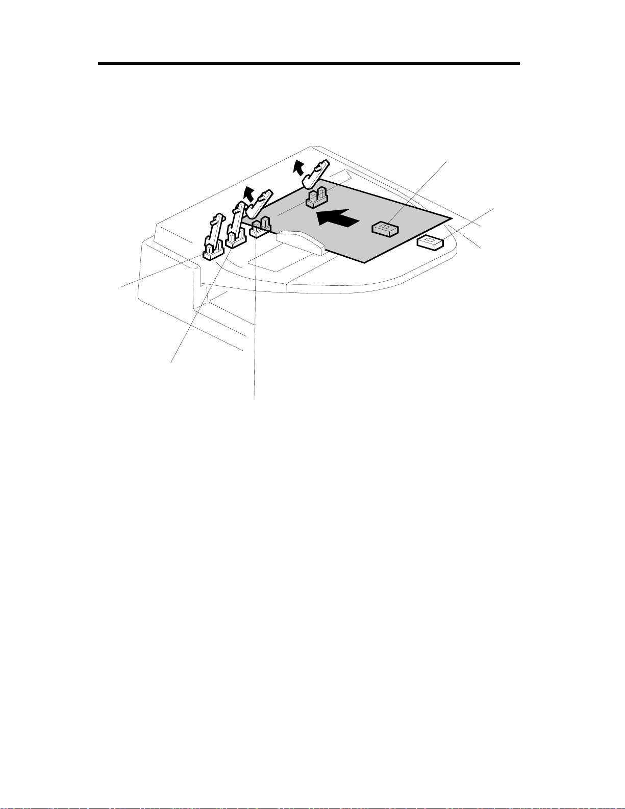
4.5 ORIGINAL SET SENSOR AND WIDTH SENSOR
REPLACEMENT
[A]
[D]
[B]
[E]
[C]
1. Open the DF feed cover.
2. Remove the entrance guide [A] (3 screws).
3. Replace the following sensors.
Original Set Sensor [B]
Original Width Sensor 1 [C]
Original Width Sensor 2 [D]
Original Width Sensor 3 [E]
A628O020.wmf
A628-18
Page 20

1 August 1996 REPLACEMENT AND ADJUSTMENT
4.6 DF COVER REMOVAL
[B]
[C]
[A]
1. Open the DF feed cover.
2. Remove the front cover [A] (3 screws).
3. Remove the original table [B] (1 screw).
4. Remove the rear cover [C] (5 screws).
A628O021.wmf
A628-19
Page 21

REPLACEMENT AND ADJUSTMENT 1 August 1996
4.7 DF FEED COVER OPEN , DF POSITION, AND APS START
SENSOR REPLACEMENT
[B]
[C]
[A]
1. Remove the rear cover.
2. Replace the following sensors.
DF Feed Cover Open Sensor [A].
DF Position Sensor [B].
APS Start Sensor [C].
A628O503.wmf
A628-20
Page 22

1 August 1996 REPLACEMENT AND ADJUSTMENT
4.8 ORIGINAL LENGTH SENSOR REPLACEMENT
[A]
[B]
[C]
1. Remove the original table.
2. Remove the original guide [A] (3 screws).
3. Replace the following sensors.
Original Length Sensor 1 [B]
Original Length Sensor 2 [C]
A623O023.wmf
A628-21
Page 23

REPLACEMENT AND ADJUSTMENT 1 August 1996
4.9 DF FEED CLUTCH AND DF PICK-UP SOLENOID
REPLACEMENT
[A]
[B]
1. Remove the rear cover.
2. Replace the following clutch and solenoid.
DF Feed Clutch [A] (2 E-rings, 1 connector)
DF Pick-up Solenoid [B] (2 screws, 1 connector)
A628O504.wmf
A628-22
Page 24

1 August 1996 REPLACEMENT AND ADJUSTMENT
4.10 REGISTRATION SENSOR REPLACEMENT
[D]
[C]
[E]
[B]
[F]
[A]
1. Remove the front cover.
2. Remove the original feed unit [A].
3. Remove the DF feed cover [B] (1 screw).
4. Remove the front two screws for the stay [C].
5. Remove the transport guide [D] (2 screws).
6. Remove the original exposure guide [E] (2 screws).
7. Replace the registration sensor [F] (1 screw, 1 connector).
A628O024.wmf
A628-23
Page 25

REPLACEMENT AND ADJUSTMENT 1 August 1996
4.11 STAMPER SOLENOID REPLACEMENT
[B]
[C]
[A]
1. Remove the front cover, original table, and rear cover.
2. Release the lever and open the original guide [A].
A628O506.wmf
3. Remove the lower original guide [B] (2 screws).
4. Replace the stamper solenoid [C] (1 screws, 1 connector).
A628-24
Page 26

1 August 1996 REPLACEMENT AND ADJUSTMENT
4.12 SP MODES
6-006-1
ADF Side-to-Side Registration
See Copy Adjustment Printing/Scanning in Replacement and Adjustment.
6-006-2
ADF Leading Edge Registration
See Copy Adjustment Printing/Scanning in Replacement and Adjustment.
6-006-3
ADF Trailing Edge Registration
See Copy Adjustment Printing/Scanning in Replacement and Adjustment.
6-007
ADF Sub-scan Magnification
See Copy Adjustment Printing/Scanning in Replacement and Adjustment.
6-009
ADF Free Run
After starting the Free Run ( 1 + # + # ), the ADF automatically starts
without exposing when an original is placed on the original table. Jams
are detected.
6-010
Stamp Position Adjustment
The default position is shown below. The position can be adjusted in the
sub-scan direction.
6-901
ADF Original Sensor Output Display
See the SP mode table.
10 ± 5mm
12 ± 5mm
A628O507.wmf
A628-25
Page 27

REPLACEMENT AND ADJUSTMENT 1 August 1996
6-902
ADF Original Scanning Method
The position [A] of the last pixel of the main scan line is changed.
0 : Original 1 : Copy paper + magnification
Example : Copying A4 size original to A3 paper at various reproduction
ratios
6-902 "0" 6-902 "1"
[A] [A]
A4
A3
A3
A3
Copy
100%
A628O508.wmf
A628-26
Page 28

1 August 1996 REPLACEMENT AND ADJUSTMENT
6-903
Original Non-waiting Start
If SP6-903 is ’0’, the next original is not fed until the trailing edge of the
current original has passed the registration sensor. This leaves a gap of
about 72 mm between originals.
If SP6-903 is ’1’, the next original is fed earlier. The gap between originals
depends on SP6-904.
6-904
Original Scanning Interval
This SP mode is effective only if SP6-903 is ’1’
Use it to adjust the distance between the trailing edge of the original and
the leading edge of the next original.
6-910
ADF/Printer Free Run
After starting the Free Run ( 1 + # + # ), the ADF automatically starts
without exposing when an original is placed on the original table. Jams
are detected.
A628-27
Page 29

COPIER INSTALLATION 1 August 1996
AUTO DOCUMENT FEEDER INSTALLATION
A628I501.wmf
[A]
A628I500.wmf
[G]
[F]
[B]
[E]
[D]
[H]
[C]
A628I502.wmf
CAUTION
Unplug the copier power cord before starting the following procedure.
NOTE:
When installing the DF, use the tool [A] in the accessory bag or a
usual screw driver.
1. Unplug the document feeder. Then, remove all tapes.
2. Remove the left scale [B] (2 screws).
3. Place the DF exposure glass [C] on the glass holder.
4. Peel off the backing [D] of the double side tape attached to the rear side of
the scale guide [E], then install the scale guide (2 screws removed in step 2).
5. Attach the original size decal [F] to the scale guide.
NOTE:
Place the decal at the rear edge, and the left side flush with the
scale paper guide [G], as shown.
6. Install the stud screws [H] for the DF on the copier.
3-8
Page 30

1 August 1996 COPIER INSTALLATION
[A]
[B]
A628I503.wmf
[C]
A628I505.wmf
7. Install the DF unit [A].
8. Slide the DF to the left, then secure the DF unit with 2 screws (M4 x 10).
9. Connect the I/F harness [B] to the copier.
10. Attach the original direction decal [C] to the DF table as shown.
11. Turn the ac and main switches on. Then, check if the document feeder
works properly.
3-9
Page 31

Auto Document Feeder (A628)
1
15
2
3
4
12
13
11
14
10
5
6
7
9
8
A628S500.wmf
Page 32

Auto Document Feeder (A628)
Symbol Index No. Description P to P (1/2)
Motors
S1 3 DF Feed N6
Sensors
S1 7 APS Start O6
S2 6 DF Position O6
S3 5 R egi stration Q6
S4 2 Feed Cover Open Sensor O6
S5 13 Original Width - 1 P6
S6 12 Original Width - 2 P6
S7 11 Original Width - 3 P6
S8 9 O rig i nal Length - 1 P6
S9 8 O rig i nal Length - 2 P6
S10 14 Original Set Q6
Solenoids
SOL1 4 DF Pick-up N6
SOL2 10 Stamper N6
Clutches
MC1 1 DF Feed N6
PCBs
PCB1 5 DF Drive O9
 Loading...