

Page 1

DOCUMENT FEEDER
DF UNIT (20-SHEET)
(C550)
Page 2
15 November 1995 OVERALL MACHINE INFORMATION
1. OVERALL MACHINE INFORMATION
1.1 SPECIFICATIONS
Original Type: Sheet-feed
Original Paper Size: Maximum 307 mm x 432 mm (12.0" x 17.0")
Minimum 90 mm x 140 mm (3.6" x 5.5")
Original Weight: 40.7 g/m2 to 127.9 g/m2, 10.8 lb to 34 lb
ADF Original Capacity: 20 sheets (66 g/m2, 17.6 lb) or 1.8 mm height
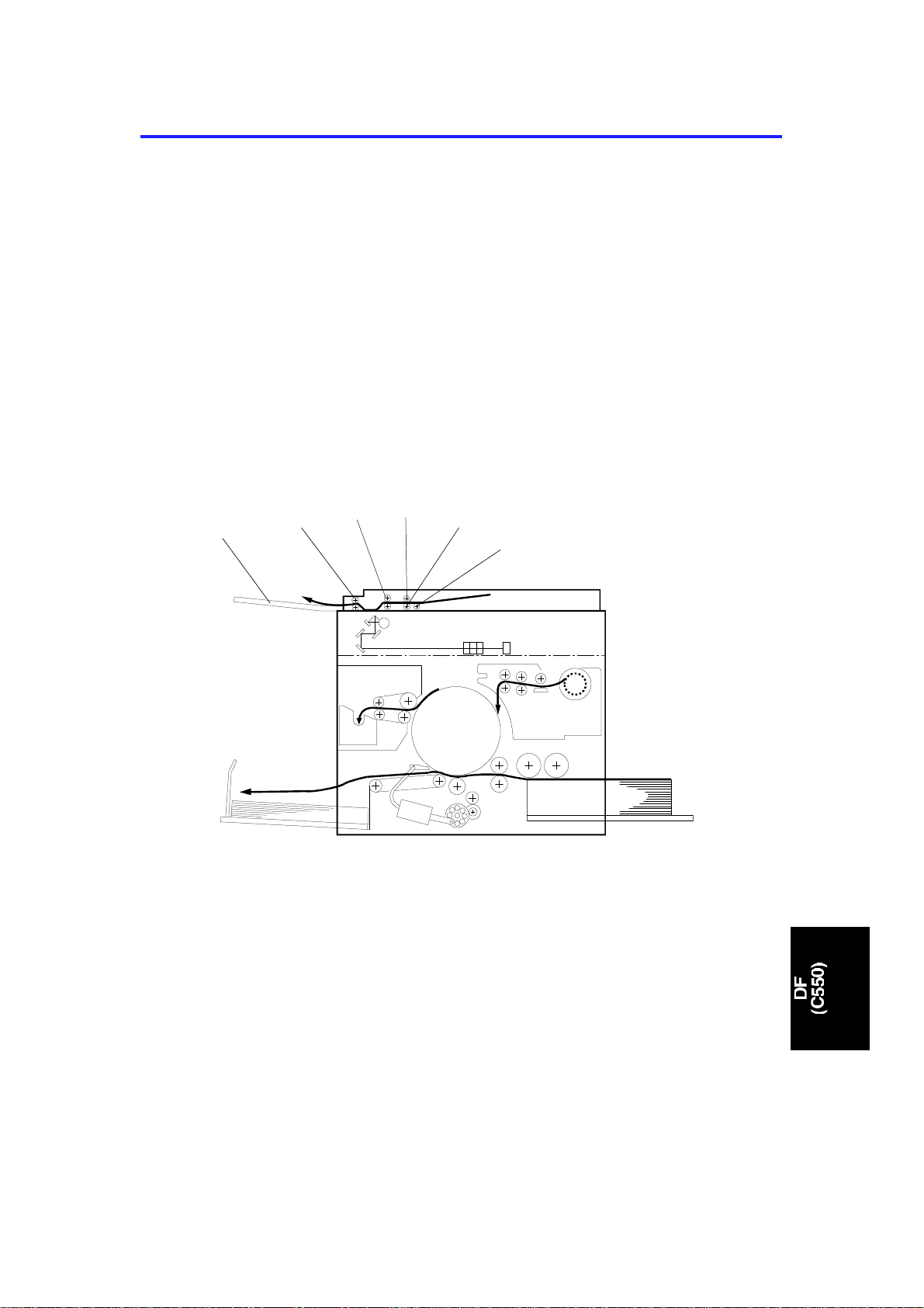
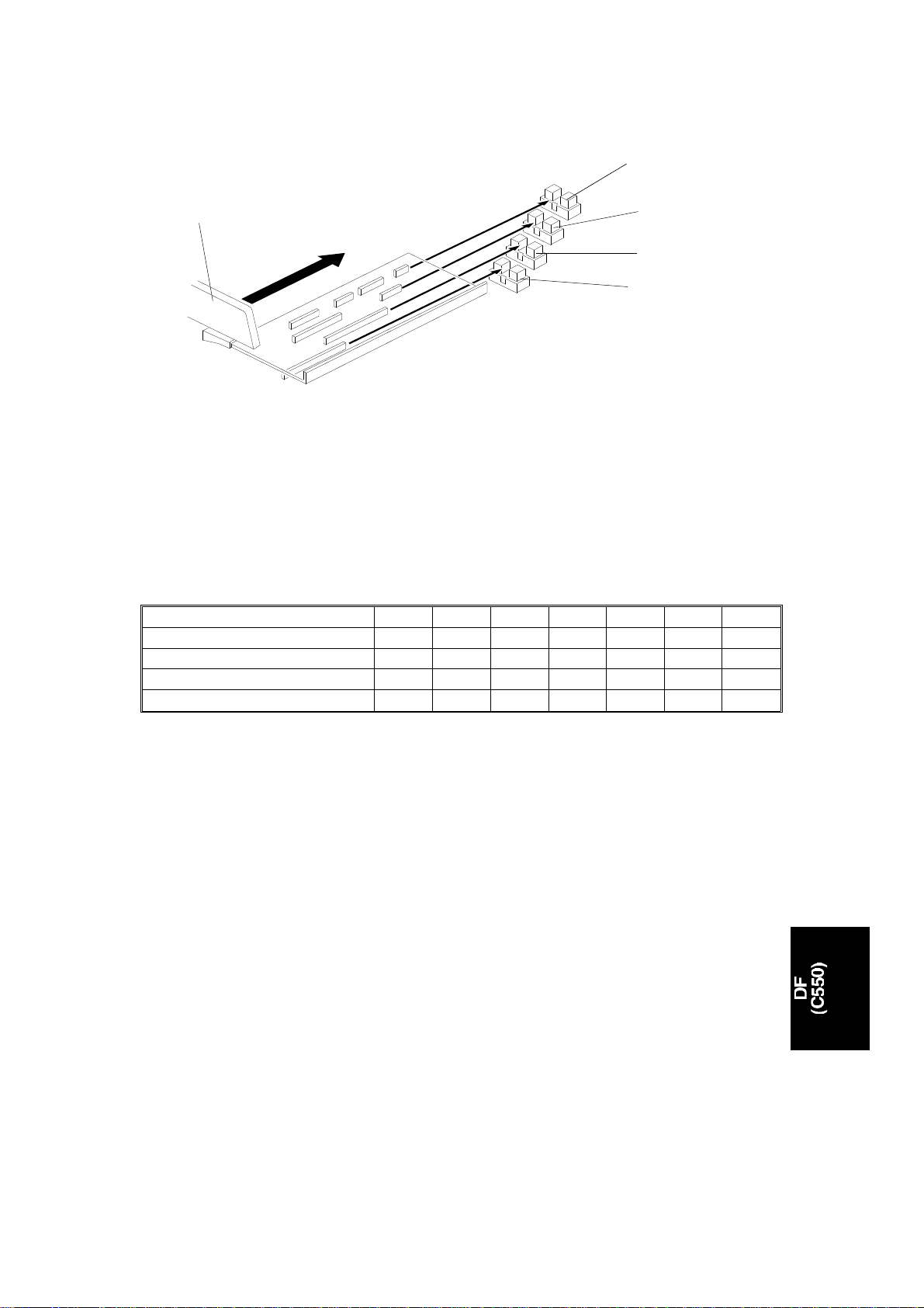
1.2 MECHANICAL COMPONENT LAYOUT
1
2
1. Original Exit Tray
2. 2nd Original Transport Roller
3. 1st Original Transport Roller
4. Separation Roller
5. Feed Roller
6. Pick-up Roller
3
4
5
6
C550V500.wmf
1
Page 3
7
OVERALL MACHINE INFORMATION 15 November 1995
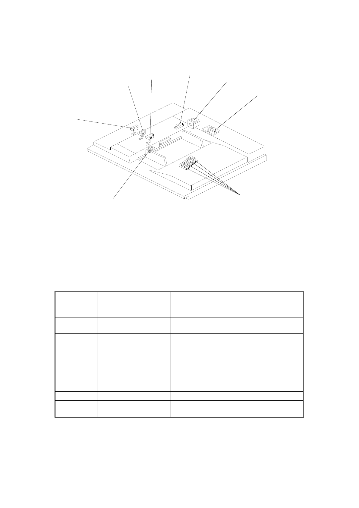
1.3 ELECTRICAL COMPONENT LAYOUT
3
2
4
5
6
1
8
C500V501.wmf
1. Original Exit Sensor 5. ADF Motor
2. Scan Line Sensor 6. ADF Interface Board
3. Original Registration Sensor 7. Original Width Sensor
4. ADF Cover Sensor 8. Original Set Sensor
COMPONENT DESCRIPTION
Index No. Name Function
1
2
3
4
5 ADF Motor Drives the ADF mechanisms.
6
7 Original Width Sensor Informs the CPU of the original width.
8
Original Exit Sensor Informs the CPU when the original activates the
sensor. Also detects original misfeeds.
Scan Line Sensor Determines the timing for scanning. Also
detects original misfeeds.
Original Registration
Sensor
ADF Cover Sensor Informs the CPU when the ADF cover is
ADF Interface Board Controls the ADF in response to signals from
Original Set Sensor Informs the CPU when an original is placed in
Determines the timing for the ADF motor to
start. Also detects original misfeeds.
opened.
the main body.
the ADF.
2
Page 4
15 November 1995 SECTIONAL DESCRIPTIONS
2. SECTIONAL DESCRIPTIONS
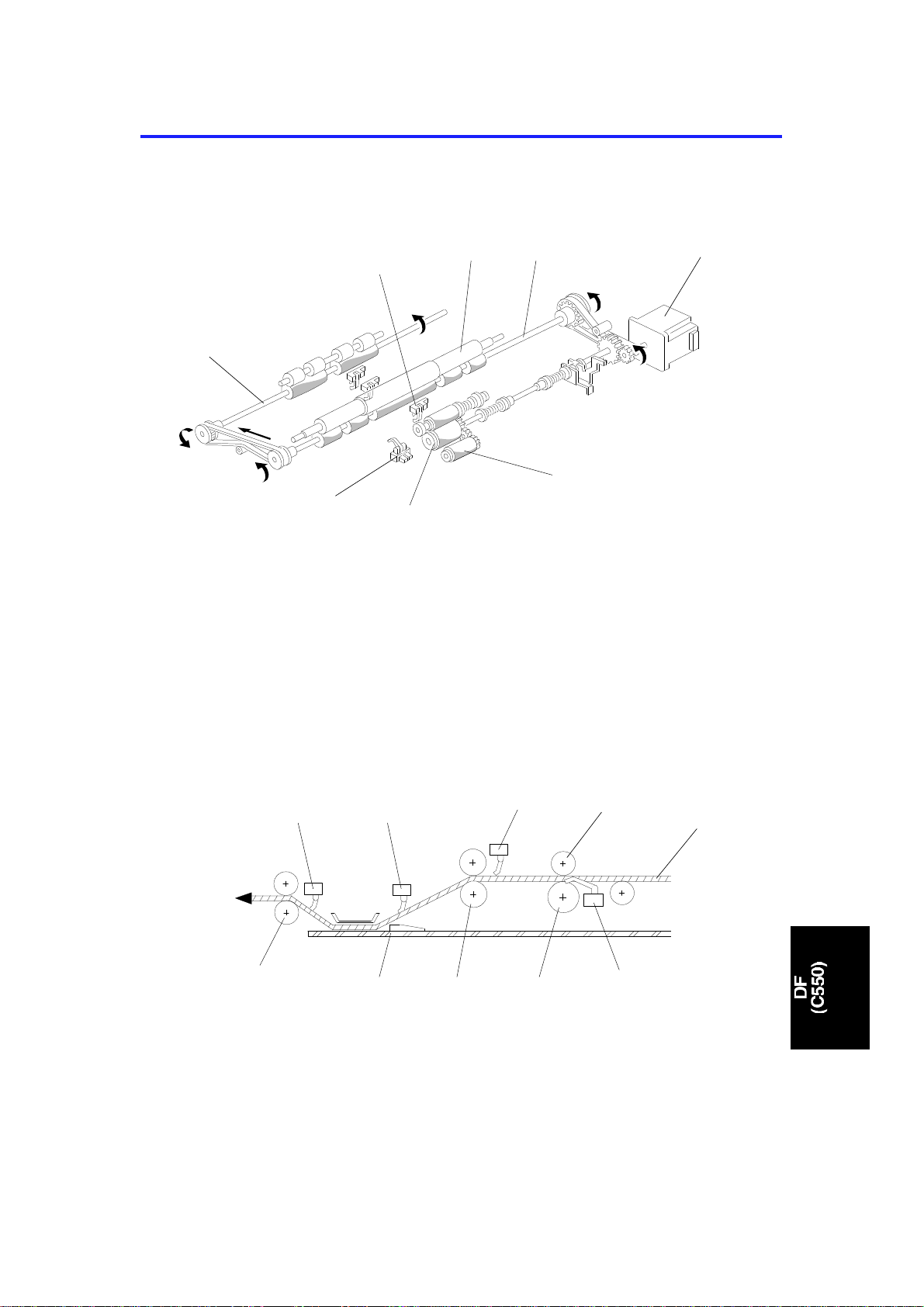
2.1 DRIVE MECHANISM
[G]
[H]
[A]
[F]
[E]
[B]
[D]
[C]
C500D500.wmf
[D]: Original Set Sensor
[G]: 1st Original Transport Roller
The ADF motor [A] is a stepper motor. The ADF motor rota te s clockwise and
then counterclockwise to fee d th e original. When the Master Making key is
pressed, the ADF motor rotates clockwise to drive the pick-up roller [B] and
the feed roller [C] turns counterclockwise to feed the bott om pa ge of the
original. When the original has been fed 14.5 mm after the original
registration sensor [ F] was act ivated, the ADF motor starts to rotate
counterclockwise. This drives the lower 1st origin al tra nsp ort ro ller [H] and
the lower original exit roller [E] counte rclockwise , feed ing the origin al.
[M]
[N]
[L]
[I]: Original Set Sensor
[J]: Feed Roller
[K]: 1st Original Transport Roller
[L]: Exposure Glass
[M]: 2nd Original Transport Roller
[O]
[K]
[P]
[J]
[Q]
[I]
C500D501.wmf
[N]: Original Exit Sensor
[O]: Scan Line Sensor
[P]: Original Registration Sensor
[Q]: Separation Roller
[R]: Original Paper Path
3
[R]
Page 5
[F]
SECTIONAL DESCRIPTIONS 15 November 1995
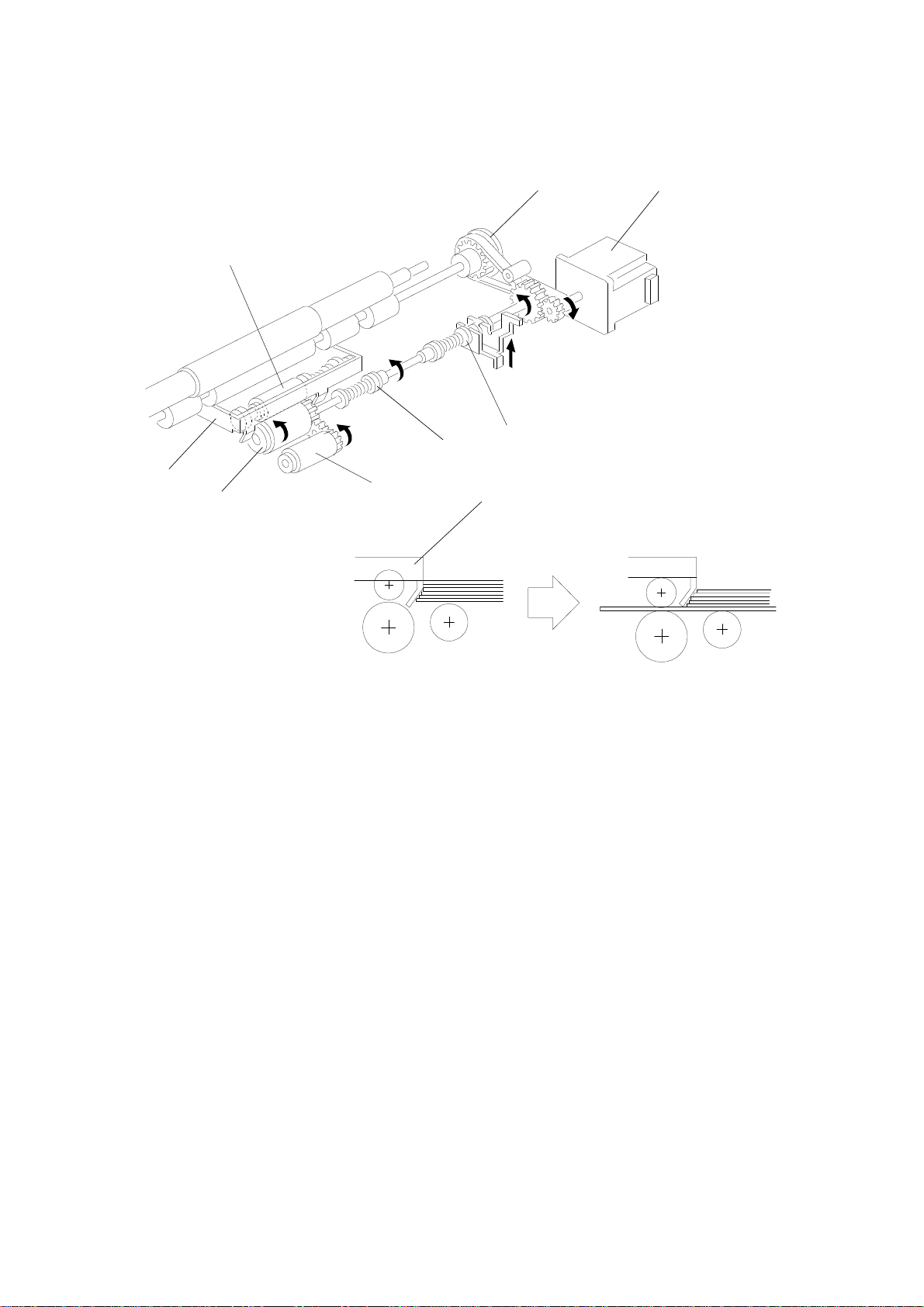
2.2 PAPER FEED AND SEPARATI O N
[E]
[D]
[G]
[H]
[C]
[B]
[A]
[C]
C500D502.wmf
C550D503.wmf
When the originals are placed on the ADF and the Master Making key is
pressed, the pick-up roller [A] starts to rota te as it is lifted by the spring clutch
[H] to touch the bott om pa ge of th e do cume nt. The original shutter [C] is lifted
by the spring clutch and the lever [G] when the ADF motor is turn ed on. The
separation roller [D] and the feed roller [B] allow only one page int o the
scanner. The one-way clutch on the fe ed roller [E] prevents its backward
rotation when the ADF motor [F] rotates coun terclockwise.
The pick-up and the shu tter torque are adju sta ble by the length of th e sprin g.
See Pick-up Torque and Shutter Torque Adjustment for details.
4
Page 6
[A]
[B]
[C]
15 November 1995 SECTIONAL DESCRIPTIONS
2.3 ORIGINAL SIZE DE TECTI O N
[E]
[D]
[A]: Original Width Senso r-0
[B]: Original Width Senso r-1
[C]: Original Width Sensor-2
[D]: Original Width Sensor-3
C550D506.wmf
There are 4 sensors (photointe rrupters) for detecting the origina l width . When
the front original guide [E] is shifted to match th e original width, the pla te [F ]
moves with the guide. Eight actuators are installe d on the plat e, and
depending on the side guide position, the sensor status will be changed.
[E]: Front Original Guide
The following table shows the relationship between the paper size and the
sensor status.
Original Size A3 DLT B4 LT/LG A4 B5 A5
Original Size Sensor-0 O O O
Original Size Sensor-1 O O O O
Original Size Sensor-2 OOOO
Original Size Sensor-3 O O O
X= Non-blocked, O= Blocked
* : All of the above original sizes are for len gthwise feed.
2.4 ORIGINAL MISFEED DETECTION
The machine indicate s an original misfeed in the followin g conditions.
• When the original registratio n sen sor do es not go ON within 3 seconds
after the ADF motor starts rotating (clockwise).
• When the scan line sensor doe s not go ON with in 2.5 seconds after the
original registration sensor is turned on.
• When the original exit sensor does not go ON afte r the scan line senso r is
turned on and the original has been fed 60 millimeters.
5
Page 7
SECTIONAL DESCRIPTIONS 15 November 1995
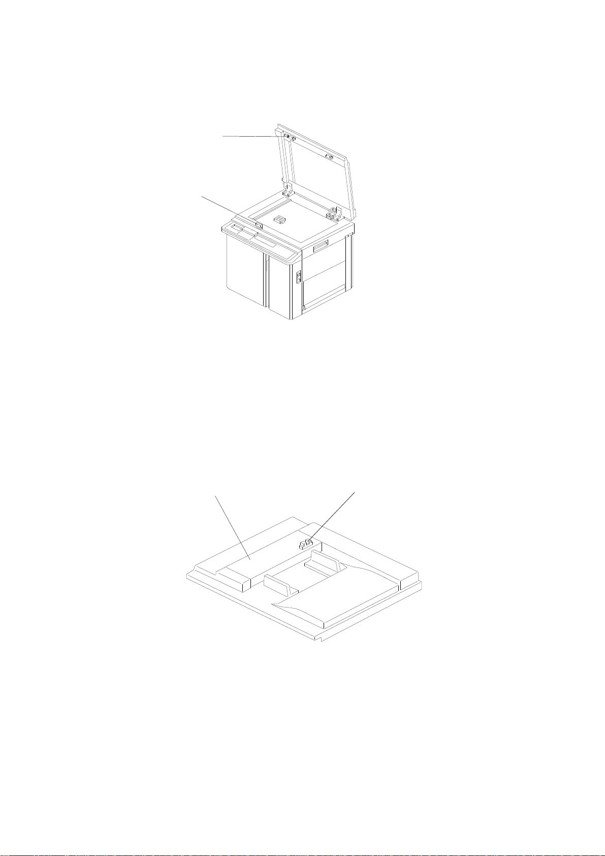
2.5 ADF OPEN/CLOSE DETECTIO N
[A]
[B]
C550D504.wmf
The ADF set sensor detects whet her t he ADF unit is opened or closed. This
sensor is a reed switch. A magnet mount ed on the ADF [A ] act ivat es th e ree d
switch [B]. When an original is pla ced in the ADF and the Master Making key
is pressed while this sensor d et ect s tha t the ADF is not closed, the mach ine
indicates "CLOSE PLA TEN COVER" on the operation display. The machine
indicates this only when the optional ADF unit is installed.
2.6 ADF POSITION DETECTI ON
[A]
[B]
C550D505.wmf
When the ADF cover [A] is opened, the plat en cover po sitio n sen sor [B ] is
deactivated. When this sensor is deactivated, the machine indicates "CLOSE
ADF COVER" on the operation display.
6
Page 8
15 November 1995 INSTALLATION PROCEDURE
3. INSTALLATION PROCEDURE
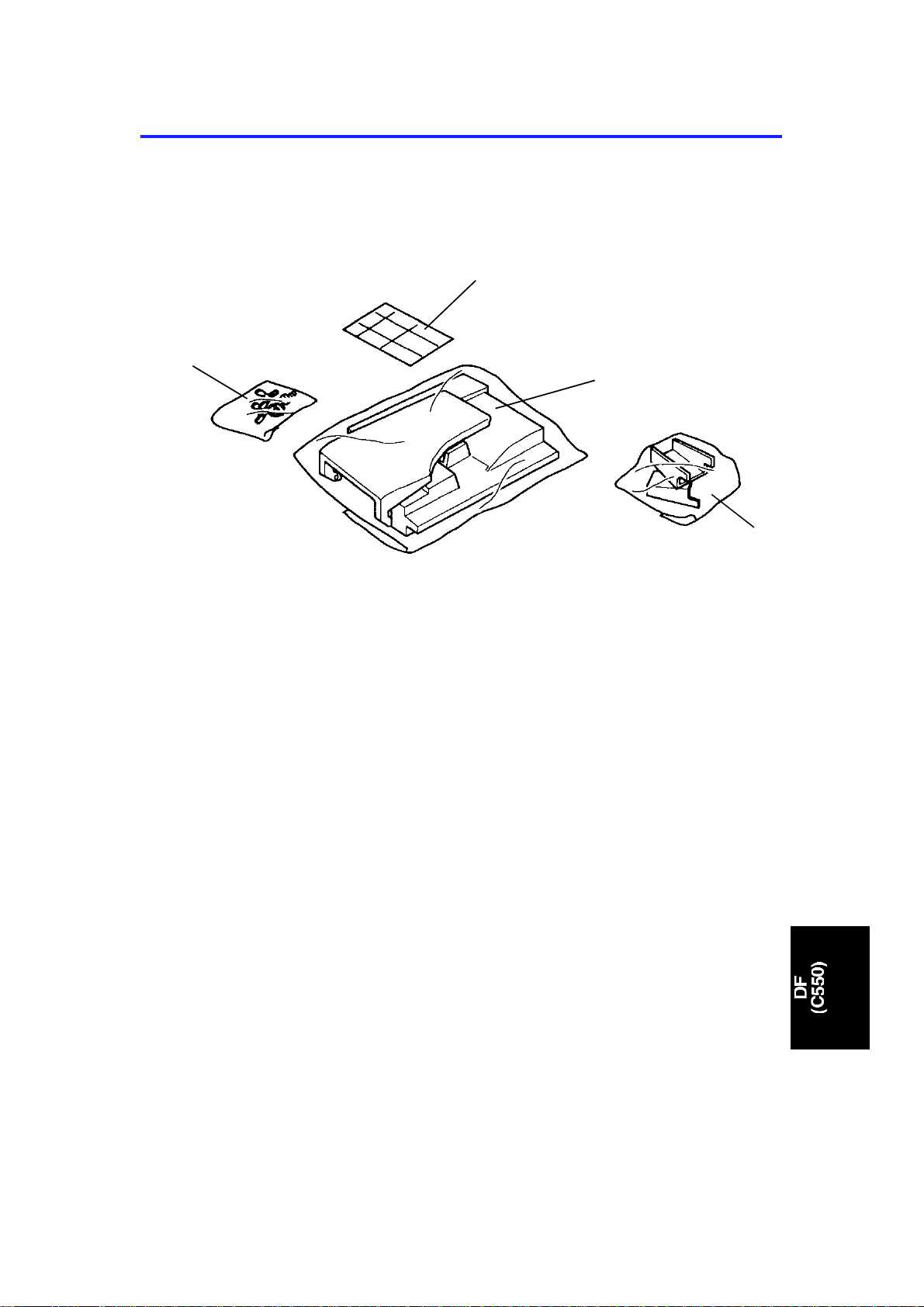
3.1 ACCESSORY CHECK
Decal Kit
Test Chart
Thumb Screws,
Screw and
Toothed Washer
Document Feeder Unit
Make sure that you have all the accesso ries liste d be low.
(1) Document Feeder Unit
(2) Bracket (2 pcs.)
(3) Screw and a Toothed Washer
(4) Thumb Screws (4 pcs.)
(5) Test Chart
(6) Installation Procedure
(7) Decal Kit
Brackets (2 pcs)
C550I500.img
7
Page 9
Pin
DF Connector
INSTALLATION PROCEDURE 15 November 1995
[A]
[B]
[C]
C550I501.img
[D]
1. Turn off the main switch an d un plu g the power cord.
2. Open the Platen Cover, remove 4 screws [A] and remove th e Pla ten
Cover.
3. Remove 3 screws [B] and remove the Upper Rear Cover.
4. Remove 2 screws [C] and remove th e cover plate.
5. Let the DF connector through the opening and mount the DF Unit as
shown in the diagram [D].
Pin
C550i502.img
6. Secure the DF Unit by 4 screws that were removed in step 2.
8
Page 10
15 November 1995 INSTALLATION PROCEDURE
[C]
[A]
[B]
C550I503.img
[D]
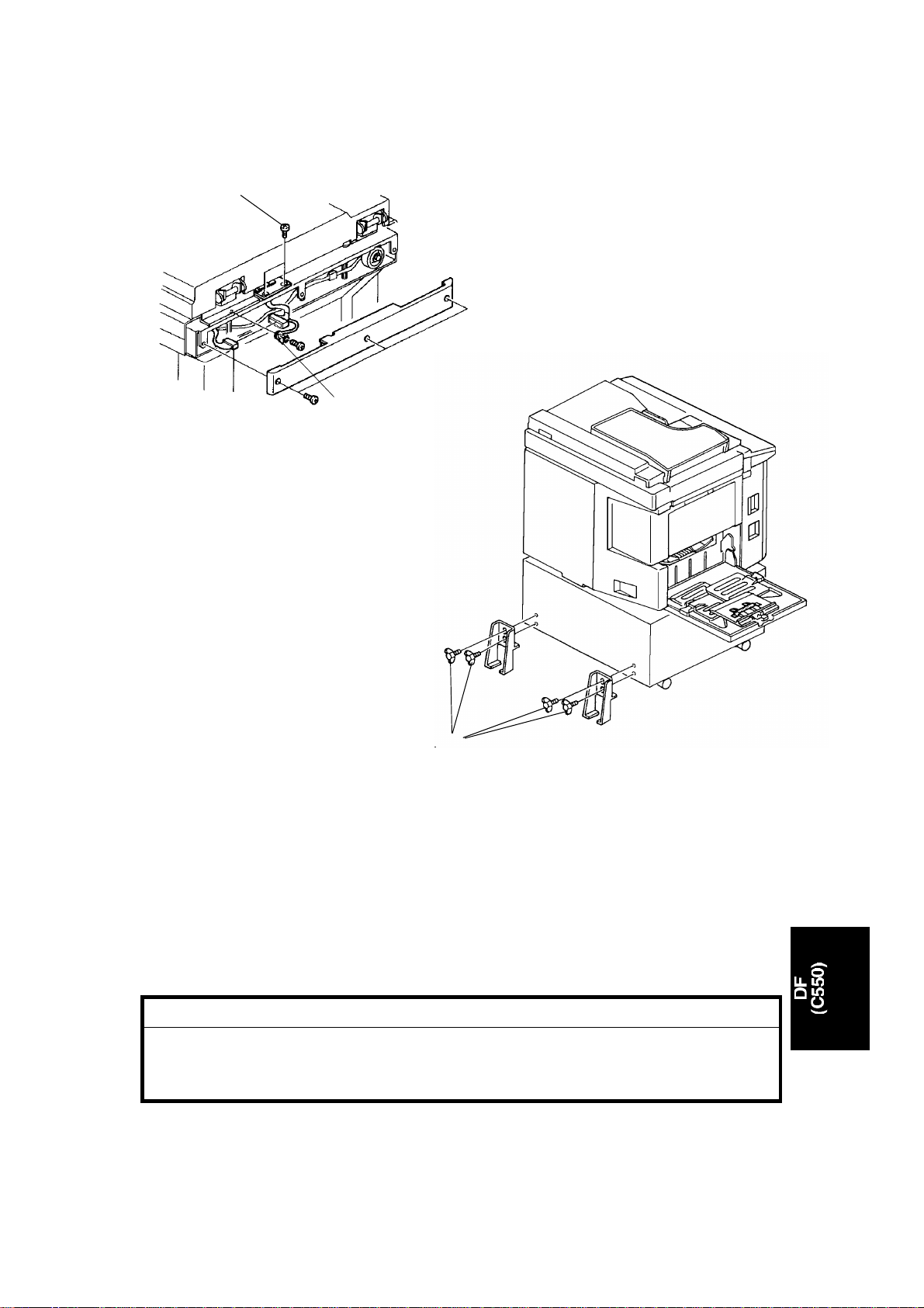
7. Close the DF and connect the connector to the scanner connector [A].
8. Secure the wire [B] by th e screw an d th e washer in the accessory.
C550I504.img
9. Secure the DF Harness Bracket by 2 screws [C].
10. Replace the Upper Rear Cover by 3 screws.
11. Secure the machine by placing 2 brackets [D] on the back of the table
using 4 thumb screws in the accessory.
CAUTION
I
The brackets must be attached to the back of the table. This is to
prevent the machine from falling over when the ADF is opened.
Also, make sure that the machine is secur ed to the table.
9
Page 11

INSTALLATION PROCEDURE 15 November 1995
When you install the optional ADF, do the following adju stme nt s.
• ADF height adjustment.
• Image center adju stment.
• Image scan magnificatio n adjustment.
10
Page 12

15 November 1995 SERVICE TABLES
4. SERVICE TABLES
4.1 USER’S MAINTENANCE
Advise the customer to clean each item regularly. Clean the followin g ite ms
at every EM call if necessary.
Cleaning Point Cleaner
Original Feed Rollers Cloth, soap, and water
4.2 PERIODIC INSPECTION
Inspect the following every 6 months.
Item Standard Procedure
Pick-up Roller
Feed Roller
Separation Roller
Wipe off paper powder using a cloth moistened with water.
11
Page 13

REPLACEMENT AND ADJUSTMENT 15 November 1995
5. REPLACEMENT AND ADJUSTMENT
5.1 ADF COVER REMOVAL
[A]
[A]
[A]
c550r500.wmf
1. Remove the screws [A] securing th e ADF cover (8 screws).
2. Disconnect the original size dete cto r harness [B].
3. Remove the harness prote cto r [C] (2 screws).
[C]
[B]
C550R501.wmf
12
Page 14

15 November 1995 REPLACEMENT AND ADJUSTMENT
5.2 ADF UNIT REMOVAL
[E]
[A]
[B]
[D]
[C]
[B]
C550r502.wmf
1. Remove the ADF cover (see section 4-1 ).
2. Open the ADF unit [A] and remove two stoppe r screws [ B] .
3. Remove the grounding wire [C] (1 screw, 1 toothed washer).
4. Disconnect the connector [D].
5. Remove the collar [E].
6. Remove the ADF unit [A] (2 bushings, 1 E-ring).
13
Page 15

[B]
REPLACEMENT AND ADJUSTMENT 15 November 1995
5.3 SEPARATION ROLLER RE MOV A L
[D]
[C]
[A]
C550R503.wmf
1. Open the ADF unit [A ].
2. Remove the separation guide plate [B] (4 screws).
3. Remove the separation roller assembly [C] (1 screw).
4. Remove the separation roller [D].
NOTE: After replacing the sepa rat ion roller, perform the sep ara tion torque
adjustment (see section 5-1 4).
14
Page 16

15 November 1995 REPLACEMENT AND ADJUSTMENT
5.4 PICK-UP ROLLER AND FEED ROLLER REMO VAL
[C]
[A]
[B]
[F]
[A]
[D]
[E]
[G]
C550R504.wmf
1. Remove the ADF cover (see section 4-1 ).
2. Remove two stopper set screws [A] and open the ADF unit [B].
3. Remove the guide plate [C] (4 screws).
4. Remove the sensor bracket [D] (2 screws).
5. Remove the pick-up roller [E] (1 clip).
6. Remove the bracket [F] (1 screw, 1 clip).
7. Remove the feed roller [G] (1 clip).
15
Page 17

REPLACEMENT AND ADJUSTMENT 15 November 1995
5.5 TRANSPORT ROLLER REMOVAL
[B]
[C]
[B]
[F]
[E]
[C]
C550D523.img
[D]
C550R505.wmf
[E]
[A]
[D]
1. Remove the ADF cover (see section 4-1 ).
C550R507.wmf
2. Remove the grip cover [A] (2 screws).
3. Remove two stopper set screws and open th e ADF un it (see sectio n 4-4).
4. Remove the guide plate (see section 4-4).
5. Remove the transport guide plate [B] (4 screws).
6. Loosen the screws [C] securing the belt tension bracket.
7. Remove the pulleys [D] (1 screw at the fron t, 1 clip at the rear).
8. Remove the transport roller [E] (2 bushings).
NOTE: When you reinstall the tra nsport guide plate [B] , make sure the guide
plate is under the white plate [F].
16
Page 18

15 November 1995 REPLACEMENT AND ADJUSTMENT
5.6 ORIGINAL REGIS TRATI ON S ENS OR REMOVAL
[B]
[D]
[A]
[A]
[C]
1. Remove the ADF cover (see section 5-1 ).
2. Remove two stopper set screws [A] and ope n th e ADF unit.
3. Remove the separation guide plate [B] (4 screws).
4. Remove the sensor bracket [C] (2 screws).
5. Remove the original registra tio n sen sor [D] (1 connector).
C550R508.wmf
17
Page 19

REPLACEMENT AND ADJUSTMENT 15 November 1995
5.7 ADF POSITION SENS OR REMOVAL
[A]
[B]
C550R509.wmf
1. Remove the ADF cover (see section 5-1 ).
2. Remove two stopper set screws and open th e ADF un it (see sectio n 5-4).
3. Remove the guide plate (see section 5-4).
4. Remove the transport guide plate [A] (4 screws).
5. Remove the ADF position sensor [B] (1 connector).
18
Page 20

[F]
15 November 1995 REPLACEMENT AND ADJUSTMENT
5.8 ORIGINAL SET SENSOR REMOVAL
[C]
[B]
[A]
[D]
[A]
[E]
[G]
C550R510.wmf
1. Remove the ADF cover (see section 5-1 ).
2. Remove two stopper set screws [A] then open the ADF unit [B].
3. Remove the guide plate [C] (4 screws).
4. Remove the harness clamp [D] (1 screw).
5. Remove the sensor bracke t [E] and the bracket [F] (2 screws).
6. Remove the original set sensor [G] (1 connector).
19
Page 21

REPLACEMENT AND ADJUSTMENT 15 November 1995
5.9 SCAN LINE SENSOR RE MOV AL
[B]
[A]
1. Remove the ADF unit (see section 5-2).
2. Remove the sensor bracket [A ] (1 screw).
3. Remove the scan line sensor [B] (1 connector).
C550R511.wmf
5.10 ORIGINAL EXIT SE NSOR REMOVAL
[B]
1. Remove the ADF unit (see section 5-2).
2. Remove the sensor bracket [A ] (1 screw).
3. Remove the original exit sensor (1 connector).
[A]
C550R512.wmf
20
Page 22

15 November 1995 REPLACEMENT AND ADJUSTMENT
5.11 ADF MOTOR REMOVAL
[D]
[B]
[E]
[A]
[C]
C550R513.wmf
1. Remove the ADF cover (see section 5-1 ).
2. Loosen the screw [A] securing the belt tension bra cket.
3. Disconnect the motor harness [B].
4. Remove the motor bracket [C] (2 screws, 1 timin g be lt).
5. Remove the ground wire [D] (1 screw).
6. Remove the ADF motor [E] (2 screws).
NOTE: • When reinstalling the moto r bracke t, slide the bracket slightly t o
the right as viewed when standing at the back of the machine.
• After reinstalling the timing belt, make sure tha t you tigh ten the
screw [A].
21
Page 23

REPLACEMENT AND ADJUSTMENT 15 November 1995
5.12 PICK-UP TORQUE AND SHUTTER TORQ UE
ADJUSTMENT
Purpose: To ensure that the originals are picked-up properly.
Adjustment Standard: The length of the sprin g for:
Pick-up: 23 ± 0.5 m m
Shutter: 26.5 ± 0.5mm
[C]
[B]
[A]
[A]
C550R514.wmf
1. Remove the ADF cover (see section 5-1 ).
2. Remove two stopper screws [A] and op en the ADF unit [B] .
3. Remove the guide plate [C] (4 screws).
23 ± 0.5 mm
26.5 ± 0.5 mm
[E]
[D]
[F]
C550R515.wmf
4. Check that the length of the pick-up and shutt er to rque springs are within
the following specifications.
Length of the pick-up spring [D] : 23 ± 0.5 mm
Length of the shutt er spring [E]: 26.5 ± 0.5 mm
5. If they are out of the specified range , adjust the spring lengths by sliding
the collar [F].
Original double feed: These springs should be shorter than the
specification.
Original non-feed: These spring s shou ld be longer th an the
specification.
22
Page 24

[D]
15 November 1995 REPLACEMENT AND ADJUSTMENT
5.13 SEPARATION ROLLE R PRE SS URE ADJ USTMENT
Purpose: To ensure that the origina ls ar e fe d properly.
[A]
[C]
[B]
C550R516.wmf
1. Open the ADF unit [A ].
2. Remove the separation guide plate [B] (4 screws).
3. Loosen the screw [C] securing the pressu re adjustment lever [D] then
move the lever to chang e th e pressure.
Original non-feed: Move the lever towards [a] (de crea se the pressure).
Original double feed: Move the lever towards [b] (increase the pre ssure ).
4. After adjusting the pressure, tighten the screw [C].
23
Page 25

REPLACEMENT AND ADJUSTMENT 15 November 1995
5.14 SEPARATION TORQUE ADJ USTME NT
Purpose: To ensure that the originals are fed properly.
Adjustment Standard: 450 gf (use a torque gauge)
[B]
[A]
C550R517.wmf
1. Open the ADF unit and remove the separatio n gu ide plate [A].
2. Adjust the separation torque by turning the bushing [B ].
Original double feed: Turn the bush ing in the [a] direction (increase th e
torque).
Original non-feed: Turn th e bu shing in the [b] direction (decrease the
torque).
5.15 ORIGINAL SKEW ADJUS TMENT
Purpose: To correct original skew.
[B]
[A]
1. Open the ADF unit [A ].
C550R518.wmf
2. Move the adjustmen t pla tes [B] to correct the skew.
3. After adjusting the skew, tig ht en the plat e pro perly.
24
Page 26

15 November 1995 REPLACEMENT AND ADJUSTMENT
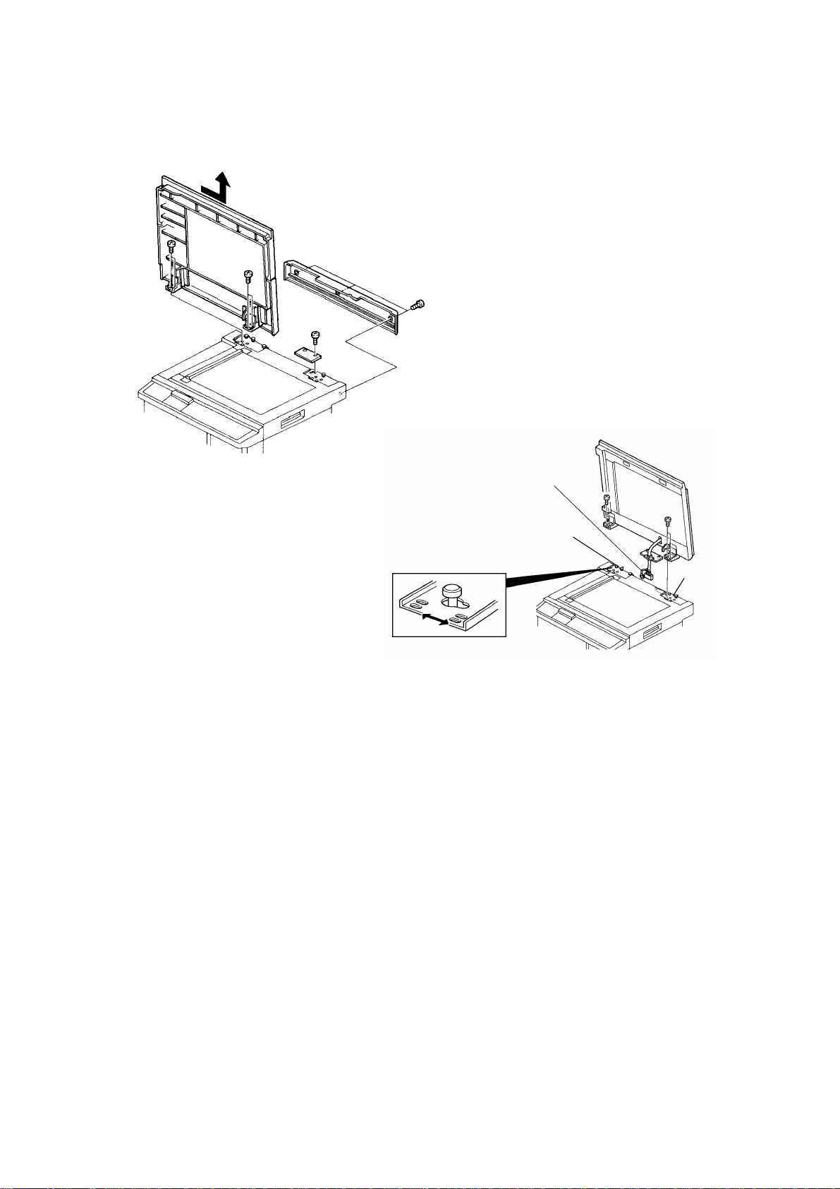
5.16 ADF HEIGHT ADJUSTMENT
Purpose: To ensure that the image can be scan ned properly.
Adjustment Standard: Less than 0.5 mm
[B]
[A]
[B]
C550R519.wmf
[D]
[C]
[C]
[E]
1. Slide the scanner unit to the left [A].
C550R520.wmf
2. Remove two positioning pin s (white) [B] under the scanner unit . The n,
attach them to the ADF as shown in the diagram.
3. Close the ADF and check that the gap [C] betwee n the positioning
pins and the scanner upper cove r is less than 0.5 mm, using a thickn ess
gauge.
4. If not, adjust the ADF height as follows.
4-1. Remove the upper rear cover (see sectio n 5-1 of the main frame’s
manual.).
4-2. Loosen the nut [D] and adjust the height by turning the knob screw
[E]. Then, tighten the nut.
5. After adjusting the ADF h eig ht, put the positioning pins back in their
previous position (under the scanner unit).
25
Page 27

ADF Feed
Direction
REPLACEMENT AND ADJUSTMENT 15 November 1995
5.17 IMAGE SCAN MAGNIFICATI ON ADJUSTMENT
Purpose: To correct the sub scan magnificat ion.
Adjustment Standard: 100 ± 0.5% in full size mode.
1. Using a test chart, make a
print in ADF mode.
2. Check that the sub scan
magnification is within the
SP No. 36
specification.
3. If it is out of specification,
adjust the sub scan
magnification using SP No. 36.
C550R521.wmf
5.18 IMAGE CENTER ADJUSTMENT (SIDE -TO -S IDE)
Purpose: To correct the center position of th e printed image.
Adjustment Standard: Less than 1 mm
NOTE: Before adjusting the image cent er po sitio n in ADF mod e, adju st it in
platen mode.
1. Using a test chart, make a print using both ADF mode and plat en mo de.
2. Compare both copies and check that the diff erence between the two
copies is within 1 mm.
3. If the differen ce is too grea t, adjust the image center using SP No. 39-1.
26
Page 28

15 November 1995 REPLACEMENT AND ADJUSTMENT
5.19 SCANNER LEADING EDGE REGI S TRATI ON
ADJUSTMENT
Purpose: To adjust the scanner start position in accorda nce wit h th e
customer’s request, or to adjust the vertica l image position of the prints to
match the original.
Standard Position:The scanning starts at 5 mm after the leading edge.
NOTE: When performing this adjustmen t, set th e prin t spe ed and the image
position to the standard positions.
1. Using a test chart, make a print using ADF mode.
2. Check the scanner start posit ion and adjust the scanner le ad ing edg e
registration using SP No. 38.
C550R522.wmf
27
Page 29

Scanner Home
Position
15 July 1994 SECTIONAL DESCRIPTION
2.6 ELECTRICAL TIMING
2.6.1 ADF (Before Scanning)
Master Making key
Original Set Sensor
Lamp Heater On
Signal
Lamp On Signal
Original Regis tra tion
Sensor
Scan Line Sensor
ADF Motor Rotation
ADF Motor
Reversing
Original Scanning
Signal
Scanner Motor
Reverse Rotation
Master Eject Process
ADF Scanning
Position
T1: When originals are inse rte d in th e ADF un it, the origin al set senso r is
activated.
T2: When the Master Makin g key is pressed, the ADF motor rota te s the
pickup roller and the feed roller to feed the bottom original into the ADF.
T3: The ADF motor stops rotating clockwise when the origin al has bee n fed
14.5 millimeters after the original registra tio n sen sor was act ivat ed. After
50 milliseconds, the ADF motor starts rotating counte rclockwise to rotat e
the 1st original transport rolle r.
T4: The ADF motor stops again when th e orig ina l has be en fed 22 millimeters
after the scan line sensor was act ivated. The ADF motor waits until the
master eject process is finished.
Scan Line Sensor On
Original
ADF Scanning Position
T5: The scanner motor rotat es cou nt erclo ckwise fo r 2.5 seconds after the
Master Making key is pressed, to bring the scanner to the ADF scanning
position.
7
Page 30

SECTIONAL DESCRIPTION 15 July 1994
2.6.2 ADF Scanning Process
Master Making Process
Original Registration
Sensor
Scan Line Sensor
Original Exit Sensor
ADF motor
Reversing
Master Plotting
Signal
ADF Motor
Speeds Up
T1: The master plotting signal is de-energized when the original has been fed
25 millimeters after the scan line sensor was deactivated. At the same
time, the ADF motor speeds up to feed out the original.
T2: The ADF motor stops when the original has been fed out 50 millimeters
after the original exit sen sor was de act ivated.
8
Page 31

To Trial Print
15 July 1994 SECTIONAL DESCRIPTION
2.6.3 Plotting
First Drum Position Sensor
Second Drum Position
Sensor
Main Motor Reversing
Scanner Home Position
Scanner Motor Advancing
Scanner Motor Reversing
ADF Motor Advancing
Master Feed Motor
Reverse Roller Clutch
Master Feed Clamper
Solenoid
Buckle Sensor
160° of Drum Rotation
218.5° of Drum Rotation
Scanner Home Position
Plotting Start
Plotting Max.
Main Motor Advancing
Left Cutter Switch
Right Cutter Switch
Cutter Motor Advancing
Cutter Motor Reversing
For C218 a: 21.5 mm b: 0.9 mm For C219 a: 18.5 mm b: 1.0 mm
e: 412 mm f: 60 mm e: 359 mm f: 61 mm
g: 40 mm c: 38 mm g: 40 mm c: 41 mm
d: 5 mm d: 5 mm
T1: After the master eject process is completed, the main mo to r starts
reverse rotation at 30 rpm. At th e same time, the master feed motor and
the reverse roller magnetic clutch tu rn on to feed the ma ste r for 21 .5
millimeters (18.5 mm for C219 model).
T2: The master feed clamp er sole no id is e ne rgize d when the drum has
rotated 160 degre es pa st the second drum position sensor (162 degrees
for the C219 model). At th e same time the reverse roller magnetic clu tch
is turned on and the scanner motor starts to rotate.
9
Page 32

SECTIONAL DESCRIPTION 15 July 1994
T3: When the scanner has move d 20 millimeters from its home position (17
mm for C219 model), the master starts to be fed. When the master has
been fed 0.9 millimeters (1.0 mm for C219 model), the thermal head
starts plotting on the master.
The leading edge is zero when the sca nner is 12 millimet ers from its
home position. The le ad ing edg e marg in can be cha ng ed to a valu e
between 4 and 10 millimeters by SP mode No.33.
T4: When the master has been fed 38 millimeters (41 mm for the C219
model), the reverse roller magn et ic clutch turns off. Then the mast er is
fed 5 millimeters more and the master feed clamper solenoid is
de-energized to close th e mast er clamper. The master is fed in the same
way as the #C210 models. The ADF mot or an d the master feed motor
speed up once the maste r plotting is done. The master fe ed ing length for
plotting is:
For #C218 models
412 millimeters: A3/DLT drum.
204 millimeters: A4/LT drum.
For #C219 models
355 millimeters: for both B4 and LG drums
T5: When the ADF motor stops, the scann er mot or sta rts to rota te clockwise
to bring back the scanner to the home posit ion .
T6: The master feed mot or stops when the master has bee n fe d 53 4. 4
millimeters (479.5 mm for the C219 model). At the same time the cutter
motor starts rota tin g to cut the master. The cut te r mo to r chan ge s the
rotation direction when th e cut ter h old er pu she s the right cutt er switch.
The cutter motor st ops wh en the cutt er ho lder goes back to the home
position to activate the left cutter switch (in th e same way a s the #C21 0
models).
When the right cutter switch is activated, th e dru m start s rota tin g to go back
to its home position.
When the left cutter switch is act ivat ed (when the cutt er comes back to its
home position), the master feed motor turn s on again to feed the master 40
millimeters.
10
Page 33

15 July 1994 SECTIONAL DESCRIPTION
2.7 CIRCUIT
Fluorescent
Lamp
Original Width Sensor-0
Original Width Sensor-1
Original Width Sensor-2
Original Width Sensor-3
Original Set Sensor
Original Registration Sensor
Scan Line Sensor
Original Exit Sensor
ADF Cover Sensor
ADF Motor
Stabilizer
ADF Interface
Board
A/D Conversion
PCB
Image Processing
PCB
Main
PCB
Component
Name
I/O
A/D Conversion PCB
CN No. Signal Level
Original Width
Sensor 0-3 In
Original Set
Sensor In 623-A3
Original
Registration
In 623-A5
Sensor
Scan Line
Sensor In 623-A8
Original Exit
Sensor
ADF Cover
Sensor
In 623-B5
In 623-B11
Description
Signal goes high when the sensors
5V
0V
5V
5V
5V
5V
5V
are interrupted by the detection
plate.
Signal goes low when the sensors
are interrupted by the detection
0V
plate.
Signal goes low when the sensors
are interrupted by the detection
0V
plate.
Signal goes low when the sensors
are interrupted by the detection
0V
plate.
Signal goes low when the sensors
are interrupted by the detection
0V
plate.
Signal goes low when the ADF
Cover is opened.
0V
11
Page 34

SECTIONAL DESCRIPTION 15 July 1994
2.8 ORIGINAL MISFEED DETECTION
The machine indicate s an original misfeed in the followin g conditions.
• When the original registratio n sen sor do es not go ON within 3 seconds
after the ADF motor starts rotating (clockwise).
• When the scan line sensor doe s not go ON with in 2.5 seconds after the
original registration sensor is turned on.
• When the original exit sensor does not go ON afte r the scan line senso r is
turned on and the original has been fed 60 millimeters.
12
 Loading...