

Ricoh Deneb-PJ2 Y069, Deneb-PJ2 Y068 Field Service Manual

Deneb-PJ2
Machine Codes: Y068/Y069
Field Service Manual
20 January, 2015


Important Safety Notices
Lead-Free Solder
This product is manufactured using lead-free solder as a part of a movement within the consumer
products industry at large to be environmentally responsible. Lead-free solder must be used in the
servicing and repair of this product.
• This product is manufactured using lead free solder. DO NOT USE LEAD BASED SOLDER TO
REPAIR THIS PRODUCT! The melting temperature of lead-free solder is higher than that of leaded
solder by 86 °F to 104 °F (30 °C to 40 °C). Use of a soldering iron designed for lead-based
solders to repair product made with lead-free solder may result in damage to the component and
or PCB being soldered. Great care should be made to ensure high-quality soldering when
servicing this product - especially when soldering large components, through-hole pins, and on
PCBs - as the level of heat required to melt lead-free solder is high.
Prevention of Physical Injury
1. Before disassembling or assembling parts of the machine and peripherals, make sure that the
machine power cord is unplugged.
2. The wall outlet should be near the machine and easily accessible.
3. If any adjustment or operation check has to be made with exterior covers off or open while the
main switch is turned on, keep hands away from electrified or mechanically driven components.
4. The machine drives some of its components when it completes the warm-up period. Be careful to
keep hands away from the mechanical and electrical components as the machine starts operation.
5. Use brackets that are strong enough to support the projector.
6. The projector must be installed in a location that is sturdy enough to support the full weight of the
projector and brackets.
Observance of Electrical Safety Standards
The machine and its peripherals must be serviced by a customer service representative who has
completed the training course on those models.
Safety and Ecological Notes for Disposal
1. Dispose of replaced parts in accordance with local regulations.
1

• To prevent a fire or explosion, keep the machine away from flammable liquids, gases, and
aerosols. A fire or an explosion might occur.
This product contains substances which are harmful to humans and the environment.
• The lamp contains mercury.
Please dispose of this product or used lamps in accordance with local regulations.
The following information is only for EU-member states:
The use of the symbol indicates that this product may not be treated as household waste. By ensuring this
product is disposed of correctly, you will help prevent potential negative consequences for the
environment and human health, which could otherwise be caused by inappropriate waste handling of
this product. For more detailed information about recycling of this product, please contact your local city
office or your household waste disposal service.
Trademarks
• DLP is trademark or registered trademark of Texas Instruments.
• IBM is a trademark or registered trademark of International Business Machines Corporation.
• Macintosh, Mac OS X, iMac, and PowerBook are trademarks of Apple Inc., registered in the U.S.
and other countries.
• Microsoft, Windows, Windows Vista, Internet Explorer and PowerPoint are either a registered
trademark or trademark of Microsoft Corporation in the United States and/or other countries.
• HDMI, the HDMI Logo and High-Definition Multimedia Interface are trademarks or registered
trademarks of HDMI Licensing LLC.
• Other product and company names mentioned in this user’s manual may be the trademarks or
registered trademarks of their respective holders.
• Blu-ray is a trademark of Blu-ray Association.
2

TABLE OF CONTENTS
Important Safety Notices................................................................................................................................... 1
Lead-Free Solder............................................................................................................................................1
Prevention of Physical Injury.......................................................................................................................... 1
Observance of Electrical Safety Standards................................................................................................. 1
Safety and Ecological Notes for Disposal................................................................................................... 1
Trademarks..................................................................................................................................................... 2
1. Product Information
Overview.............................................................................................................................................................7
Main Unit........................................................................................................................................................ 7
Control Panel.................................................................................................................................................. 8
Connection Ports.............................................................................................................................................9
Specifications....................................................................................................................................................10
General Specifications................................................................................................................................ 10
Compatible Mode....................................................................................................................................... 12
Computer compatibility (for PC, Video, DVI, HDMI).......................................................................12
3D timing table (Only support XGA, WUXGA does not support 3D function)............................. 15
Computer compatibility for MAC...................................................................................................... 16
Lamp Information......................................................................................................................................... 17
Lens............................................................................................................................................................... 17
Diagram............................................................................................................................................................ 21
2. Installation
Installation Requirements................................................................................................................................. 23
Environment/Power Requirements............................................................................................................. 23
Machine Space Requirements....................................................................................................................23
Machine Dimensions................................................................................................................................... 23
Main Machine Installation...............................................................................................................................24
Accessory Check..........................................................................................................................................24
Precautions................................................................................................................................................... 25
Do..................................................................................................................................................................25
Do not........................................................................................................................................................... 25
3. Replacement and Adjustment
Special Tools.................................................................................................................................................... 27
Equipment Needed..........................................................................................................................................28
3

Parts List.............................................................................................................................................................29
Service Parts List........................................................................................................................................... 29
Part Replacement..............................................................................................................................................31
Lens Ring Cover, Projector Lens..................................................................................................................31
Lamp Unit......................................................................................................................................................33
Top Cover, IR-T Sensor................................................................................................................................34
Rear Cover................................................................................................................................................... 35
Main Board, I/O Board, LAN Board........................................................................................................36
Connector list.......................................................................................................................................40
Blower Module............................................................................................................................................ 42
Top blower and duct...........................................................................................................................42
TC blower............................................................................................................................................ 43
Bottom blower..................................................................................................................................... 44
System Fan....................................................................................................................................................45
Main Board Shielding and Front Shielding............................................................................................... 47
Front Cover, LED Board, LED Cover, Thermal Board, IR Cover.............................................................. 48
Right Cover, Lamp Cover, Interlock switch................................................................................................50
Left Cover, Keypad Rubber, Keypad Board, Interrupt switch..................................................................51
Optical Engine............................................................................................................................................. 54
Color Wheel, Photo Sensor Board.............................................................................................................55
DA module....................................................................................................................................................56
DC Motor, Horizontal/Vertical Sensor..................................................................................................... 57
Thermal Switch.............................................................................................................................................58
Ballast........................................................................................................................................................... 59
PSU................................................................................................................................................................60
DMD Fan...................................................................................................................................................... 61
Bottom Cover, Bottom Shielding, AC inlet, Adjustable Foot.................................................................... 61
Required Action after Replacing Parts ...........................................................................................................64
Adjustment........................................................................................................................................................ 66
Rod Adjustment............................................................................................................................................ 66
Focus Adjustment......................................................................................................................................... 67
4. Troubleshooting
Equipment Needed..........................................................................................................................................69
4

Front Panel LEDs............................................................................................................................................... 70
Main Procedures.............................................................................................................................................. 72
A. No Power Troubleshooting.................................................................................................................... 73
B. Power Troubleshooting........................................................................................................................... 73
C. Image Performance Troubleshooting.................................................................................................... 78
D. Remote Control Troubleshooting........................................................................................................... 86
E. Network Troubleshooting....................................................................................................................... 88
RS232 Error Log Troubleshooting.................................................................................................................. 90
Equipment Needed......................................................................................................................................90
Procedure..................................................................................................................................................... 90
5. Test & Inspection
Service Mode and Engineering Mode...........................................................................................................93
Service Mode...............................................................................................................................................93
How to enter the Service Mode.........................................................................................................93
Service Mode settings.........................................................................................................................93
Engineering Mode.......................................................................................................................................95
How to enter the Engineering Mode................................................................................................. 95
Engineering Mode settings.................................................................................................................95
Test Equipment and Conditions.......................................................................................................................98
Test Equipment Needed.............................................................................................................................. 98
Recommended Test Condition.................................................................................................................... 98
Calibration........................................................................................................................................................99
Lens Calibration........................................................................................................................................... 99
DA Calibration............................................................................................................................................. 99
Fan Calibration..........................................................................................................................................100
Lamp Hours.................................................................................................................................................... 102
Reset Lamp Hour........................................................................................................................................102
Re-write Lamp Hours.................................................................................................................................102
Color Wheel Index........................................................................................................................................104
Test Inspection Procedure............................................................................................................................. 105
Function Inspection....................................................................................................................................105
Check points.............................................................................................................................................. 105
OSD Reset..................................................................................................................................................106
5

Network Test.................................................................................................................................................. 107
6. Firmware Update
PIC, PW392, DDP4421/DDP4422 FW Update......................................................................................109
Equipment Needed................................................................................................................................... 109
Firmware Update Procedure.................................................................................................................... 109
Connection........................................................................................................................................109
Download software and update..................................................................................................... 110
Check PW392, PIC, DDP4421/DDP4422 FW Version .....................................................................113
LAN Firmware Update.................................................................................................................................. 114
Equipment Needed................................................................................................................................... 114
Connect the Projector & Check the LAN Setting.....................................................................................114
PC Network Setting...................................................................................................................................116
Proxy Setting.............................................................................................................................................. 117
LAN FW Update Procedure..................................................................................................................... 118
Check LAN FW Version............................................................................................................................121
Re-write Serial Number.................................................................................................................................122
Equipment Needed................................................................................................................................... 122
Re-write Serial Number............................................................................................................................ 122
Connection........................................................................................................................................122
Re-write serial number......................................................................................................................123
Check Serial Number (SN)...................................................................................................................... 124
6
1. Product Information
Overview
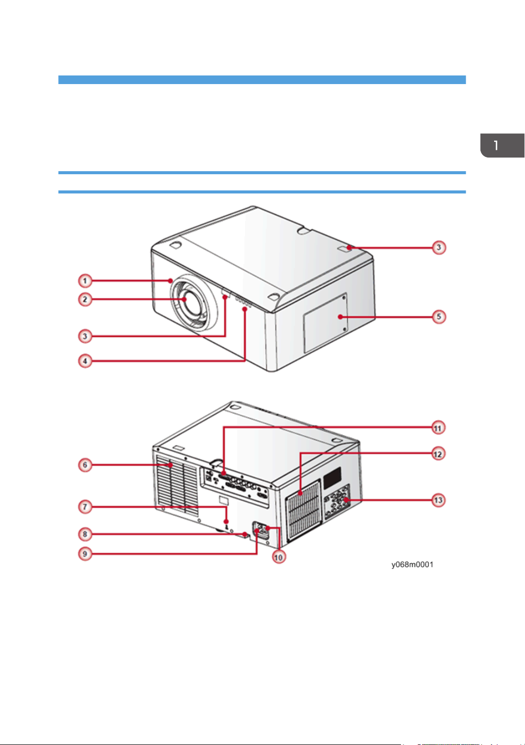
Main Unit
1. Lens ring
2. Zoom lens
3. IR receivers
4. LED indicators
5. Lamp door
7
1. Product Information
6. Outlet vent
7. Kensington lock
8. Security bar
9. Power connector
10. Power switch
11. Connector panel
12. Inlet vent & filter
13. Keypad panel
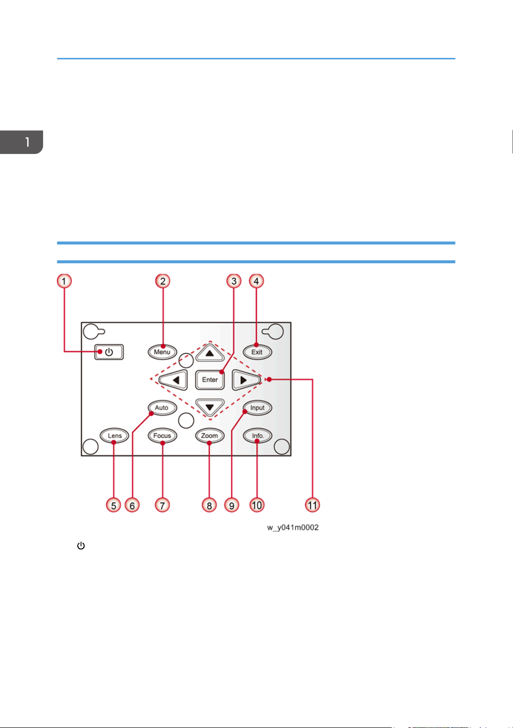
Control Panel
1. / Power key
2. Menu key
3. Enter key
4. Exit key
5. Lens key
6. Auto key
7. Focus key
8
8. Zoom key
9. Input key
10. Info. key
11. Four directional select keys
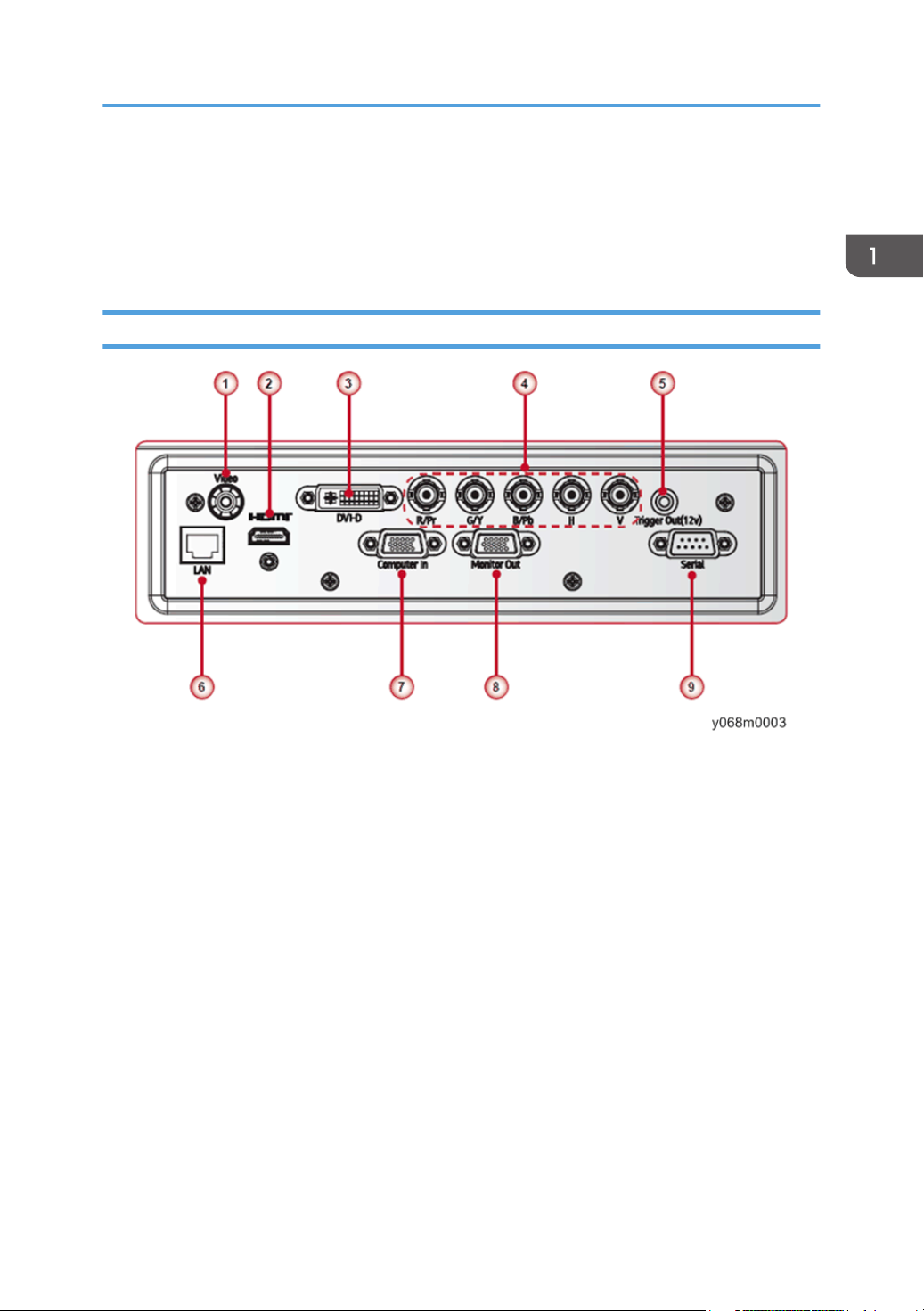
Connection Ports
Overview
1. Composite video input connector
2. HDMI connector
3. DVI-D connector
4. BNC connector
5. Trigger out connector
6. LAN connector
7. Computer in connector
8. Monitor out connector
9. Serial connector (9-pin Dsub type)
9
1. Product Information
Specifications
General Specifications
No Item Description
1 Technology
2 Dimension (W x D x H) 452.8 x 389.9 x 205.5 mm (without lens, w/o elevators)
3 Weight
4 Power supply
5 Keystone correction V: +/- 20 degree
6 Resolution
7 Power consumption
“TI” 0.7” XGA DMD, Type A, DC3 / “TI” 0.67” WUXGA DMD,
Type A, DC3
• Net weight (w/o lens): 13.9 kg
• Weight with package (w/o lens): 17.3 kg
Auto-ranging: 100V ~ 240V ± 10%, 50-60Hz
• 465W Lamp @ Normal operation
• 360W Lamp @ ECO operation
• Native resolution:
XGA (1024x768) / WUXGA (1920x1200)
• Supported Resolution:
Up to WUXGA@60Hz (Reduced Blanking) & UXGA@60Hz
• Normal Brightness mode: 580W+/-10%@ 110VAC
• ECO Brightness mode: 450W+/-10%@ 110VAC
• Standby mode (LAN off) < 0.5W
10
8 Throw ratio (XGA)
9 Lamp life
• 0.99-1.26 (Replacement Lens Type 5)
• 1.26-1.58 (Standard Lens Type 2)
• 1.58-3.00 (Replacement Lens Type 6)
• 3.00-5.70 (Replacement Lens Type 7)
• TBA (Replacement Lens Type 9)
• Normal mode: 1500 hours standard @465W, 50% survival
rate
• ECO mode: 2000 hours typical @360W, 50% survival rate
No Item Description
• NTSC: NTSC M 3.58MHz, 4.43MHz
• PAL: PAL B/D/G/H/I/M/N, 4.43MHz
Specifications
10 Video compatibility
11 Brightness
12 Contrast ratio
*1
• SECAM: SECAM B/D/G/K/K1/L, 4.25/4.4 MHz
• SDTV: 480i/p, 576i/p
• HDTV: 720p(50/60Hz), 1080i/p(50/60Hz), 1080p
24\25\30\50\60 Hz
• Typical:
6,300(XGA) /5,500(WXGA)
• Minimum:
5,600(XGA) /4,900(WXGA)
• Typical:
Full on/ Full
off
1,200:1 (XGA) / 1150:1 (WXGA)
• Minimum:
900:1 (XGA) / 1000:1 (WXGA)
• Typical:
250 (XGA) / 250 (WXGA)
ANSI
• Minimum:
150 (XGA) / 150 (WXGA)
13 Uniformity (TBD)
*2
Dynamic
ON
JBMA
Standard
(Lens
Center)
ANSI
Standard
(Lens
Center)
• Typical:
4,400:1 (XGA) / 4,400:1 (WXGA)
• Typical:
90% (XGA) / 90% (WXGA)
• Minimum:
65% (XGA) / 70% (WXGA)
• Typical:
+/-30% (XGA) / +/-30% (WXGA)
• Minimum:
+/-35% (XGA) / +/-35% (WXGA)
11
1. Product Information
No Item Description
• 6 Segment—RGBCYW, Filter Diameter: 56mm
14 Color wheel
15 Lamp 465W, arc 1.1
16 Projection lens See the section about the Lens (page 17 "Lens")
17 Temperature
18 Altitude
*1 ANSI contrast is verified in bright display mode and normal brightness mode.
Contrast spec is based on standard lens type 2. Other lens contrast will be different.
*2 Uniformity is measured in bright display mode, normal brightness mode and lens shift on center.
Contrast spec is based on standard lens type 2. Other lens contrast will be different.
• Filter Segment: 6S R81 Y41 G84 C31 W52 B71
• 2X, 7200RPM (120Hz) & 3X, 10800RPM (180Hz)
• Operating: 5°C ~ 40 °C (0~40 °C for tests only)
• Non-operation: -20°C ~ 60°C
• Operating:
for 0 ~ 2500 ft, 5 ~ 40°C
for 2500 ~ 5000 ft, 5 ~ 35°C
for 5000 ~ 10000 ft, 5 ~ 30°C
• Non-operation: Sea Level to 40,000 feet
The ANSI uniformity at dark corner as lens offset for XGA is -70% (Min.) (TBD)
Compatible Mode
Computer compatibility (for PC, Video, DVI, HDMI)
12
Frequen
Signal Resolution
NTSC - 15.734 60 O - -
PAL/
SECAM
- 15.625 50 O - -
640 x 350 31.5 70.1 O O 70Hz
cy H.
[KHz]
Refresh
rate
[Hz]
Video Digital Analog Remark
Specifications
Signal Resolution
Frequen
cy H.
[KHz]
Refresh
rate
[Hz]
Video Digital Analog Remark
640 x 400 37.9 85.1 O O 85Hz
720 x 400 31.5 70 O O
720 x 576 50 O O
VGA 640 x 480 31.5 60 O O
VGA 640 x 480 67 O O
VGA 640 x 480 37.9 72.8 O O 72Hz
VGA 640 x 480 37.5 75 O O
VGA 640 x 480 43.3 85 O O
SVGA 800 x 600 35.2 56.3 O O 56Hz
SVGA 800 x 600 37.9 60.3 O O 60Hz
SVGA 800 x 600 46.9 75 O O
SVGA 800 x 600 48.1 72.2 O O 72Hz
SVGA 800 x 600 53.7 85.1 O O 85Hz
XGA 1024 x 768 48.4 60 O O
XGA 1024 x 768 56.5 70.1 O O 70Hz
XGA 1024 x 768 60 75 O O
XGA 1024 x 768 68.7 85 O O
HD720 1280 x 720 50 O O
HD720 1280 x 720 60 O O
WXGA 1280 x 768 47.776 60 O O
WXGA 1280 x 768 75 O O
WXGA 1280 x 768 85 O O
WXGA-800 1280 x 800 60 O O
13
1. Product Information
Signal Resolution
Frequen
cy H.
[KHz]
Refresh
rate
[Hz]
Video Digital Analog Remark
SXGA 1280 x 1024 64 60 O O
SXGA 1280 x 1024 80 75 O O
SXGA 1280 x 1024 91.1 85 O O
SXGA+ 1400 x 1050 60 O -
UXGA 1600 x1200 75 60 O O
HD1080 1920 x 1080 24 O O
HD1080 1920 x 1080 50 O O
HD1080 1920 x 1080 60 O O
WUXGA 1920 x 1200 60 O O
HDTV 1920 x 1080 33.8 30 O - -
1920 x 1080 28.1 25 O - -
Only support
[RB] timing
14
1920 x 1080i 28.125 50 - O
1920 x 1080i 33.75 60 - O
1920 x
1080p
1920 x
1080p
1920 x
1080p
1920 x
1080p
24 - O
25 - O
30 - O
50 - O
O
(SOG)
O
(SOG)
O
(SOG)
O
(SOG)
O
(SOG)
O
(SOG)
Specifications
Signal Resolution
1920 x
1080p
Frequen
cy H.
[KHz]
Refresh
rate
Video Digital Analog Remark
[Hz]
60 - O
(SOG)
1280 x 720 45 60 O - -
1280 x 720p 50 - O
(SOG)
1280 x 720p 60 - O
(SOG)
SDTV 720 x 576 31.3 50 O - -
720 x 576i 15.625 50 - O
(SOG)
720 x 576p 50 - O
(SOG)
O
O
O
O
O
720 x 480 31.5 60 O - -
O
720 x 480i 15.734 60 - O
(SOG)
O
720 x 480p 31.5 60 - O
(SOG)
• “O” expressed support this type of signal and “-” expressed that does not support this type of
signal.
3D timing table (Only support XGA, WUXGA does not support 3D function)
Input Signal Resolution V Freq.(Hz) H Freq.(kHz)
SVGA 800 x 600 119.63 76.92 83.725
Pixel Clock
(MHz)
Video Image
sequential
Frame
15

1. Product Information
Input Signal Resolution V Freq.(Hz) H Freq.(kHz)
XGA 1024 x 768 120.13 98.87 139.276
720p 1280 x 720 120.31 92.88 161.997
Pixel Clock
(MHz)
Video Image
Frame
sequential
Frame
sequential
Computer compatibility for MAC
Mac book Pro
(Intel)
compatibility
Power Mac G5
compatibility
Resolution Hz
Mac book
compatibility
Digital Analog Digital Analog Digital Analog Digital Analog
800x600 60 O O O O - - O -
800x600 72 O O O O - O O O
800x600 75 O O O O - O O O
Power Mac G4
compatibility
800x600 85 O O - O - O O O
1024x768 60 O O O O - O O O
1024x768 70 O O O O - O O O
1024x768 75 O O O O - O O O
1024x768 85 O O O O - O O O
1280x720 60 O O O O - O O O
1280x768 60 O O O O - - - O
1280x768 75 - O - O - O O O
1280x768 85 - O - O - - - O
1280x800 60 - O - O - O O O
1280x102
4
60 O - - O - O O O
16
Specifications
Mac book
Resolution Hz
1280x102
4
1920x108
0
1920x120
0
(*1)
(*1) 1920 x 1200 @60Hz only support RB (reduced blanking)
• “O” expressed support this type of signal and “-” expressed that does not support this type of
signal.
75 O - - O - O O -
60 O - - O - O O O
60 O - - O - O O O
compatibility
Digital Analog Digital Analog Digital Analog Digital Analog
Mac book Pro
(Intel)
compatibility
Power Mac G5
compatibility
Power Mac G4
compatibility
Lamp Information
Type 465W, arc 1.1
• Normal mode: 1500 hours standard @465W, 50%
survival rate
Lamp life
Lamp power
• ECO mode: 2000 hours typical @360W, 50%
survival rate
Above spec only claimed for table top and ceiling mount,
CW @2X
• Normal mode: 465W ± 3%
• ECO mode: 360W
Lens
XGA/WUXGA: Type 2 is the standard lens.
Description
17

1. Product Information
Projection
lens
Focal length
(f)
Replacement
Lens Type 5
14.03-17.96
Standard
Lens Type 2
18.07-22.5
9
Replacement
Lens Type 6
Replacement
Lens Type 7
Replacement
Lens Type 9
22.56-42.87 42.68-80.90 TBA
F number 2.30-2.57 2.00-2.32 2.30-3.39 2.30-2.74 TBA
Focus spec
(MTF)
Zoom range
(ratio)
67 lp/mm 47 lp/mm 67 lp/mm 67 lp/mm TBA
1.28X 1.25X 1.9X 1.9X TBA
Zoom &
focus
Motorized
adjustment
Throw ratio
(XGA)
0.99-1.26 1.26-1.58 1.58-3.00 3.00-5.70 TBA
Throw
distance
1.01~7.68m 1.28~9.63m 1.61~18.29m 3.05~34.75m TBA
(XGA)
Projection
image size
50~300”
18
Specifications
Projection
lens
Motorized
lens shift
Replacement
Lens Type 5
Standard
Lens Type 2
Replacement
Lens Type 6
XGA, WUXGA: (Dim corner is larger than 50%)
Horizontal: +/-15% (typical; tolerance +/-4%)
Vertical: +/-50% (typical; tolerance +/-4%)
Replacement
Lens Type 7
Replacement
Lens Type 9
Lens shift accuracy: 0.5 pixel per step
When the lens is shifted beyond the recommended range for operation, the screen
edges may become darker or the images may become out of focus.
Keystone
correction
V: +/- 20 degree
Leakage <=0.8 Lx @ screen size diagonal 83” outside of active area
<+/- 1.0% @ 100” screen size
(all lens shift area, all optional lens)
Distortion
Horizontal distortion = (A-C)/C (up) and (B-C)C (down)
Vertical distortion = (D + E - 2F)/2F
19

1. Product Information
Projection
lens
Replacement
Lens Type 5
Standard
Lens Type 2
1 pixel (core pixel) XGA=3.2mm @ 100“ screen
Flare
2.Green flare<=2.5 pixels (Observable from 1.5m)
3.Blue/Red flare<=2.5 pixels (Observable from 1.5m)
Unbalance <50cm @100” full range for all lens.
Thermal drift
of focus
About 45cm @100” after 1 hr. burn-in
Replacement
Lens Type 6
Replacement
Lens Type 7
Replacement
Lens Type 9
20
Diagram
Diagram
21
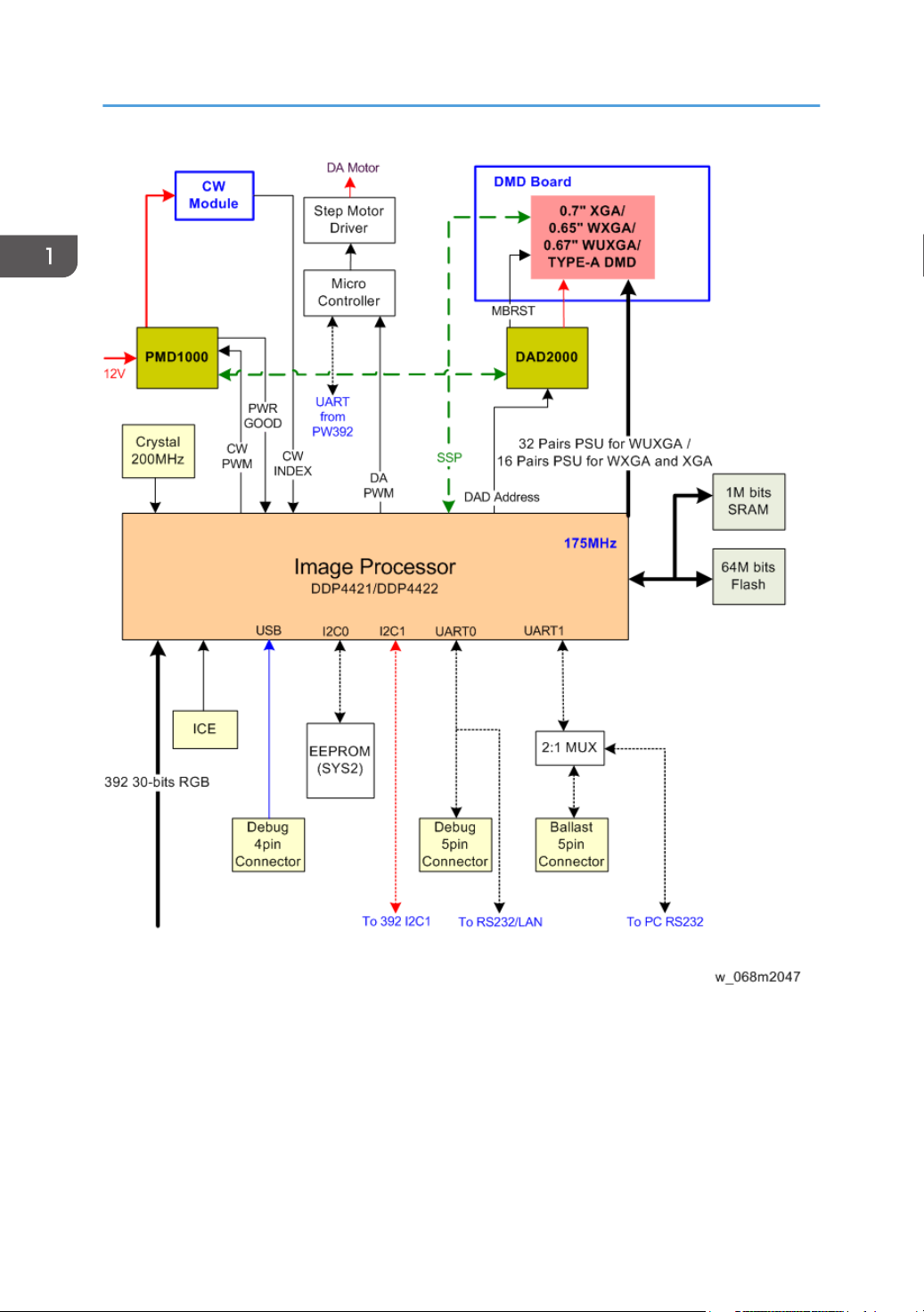
1. Product Information
22
2. Installation
Installation Requirements
Environment/Power Requirements
Operating temperature
5ºC to 40ºC / 41°F~104°F
Power supply
100~240VAC ± 10%, 50~60Hz (Auto-ranging and power factor correction)
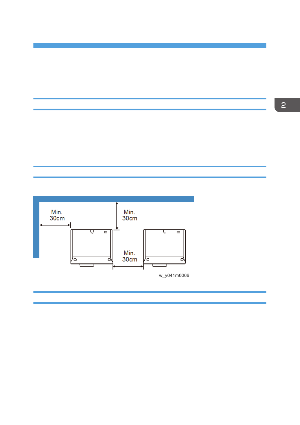
Machine Space Requirements
Do not block projector in/out air vents and keep 30 cm clearance around vents for air flow.
Machine Dimensions
453 mm (W) x 390 mm (D) x 212 mm (H) (without lens, with elevators)
23
2. Installation
Main Machine Installation
The user must set this projector up.
• About the handling of this machine, follow the contents with reference to Safety Information of the
user manual.
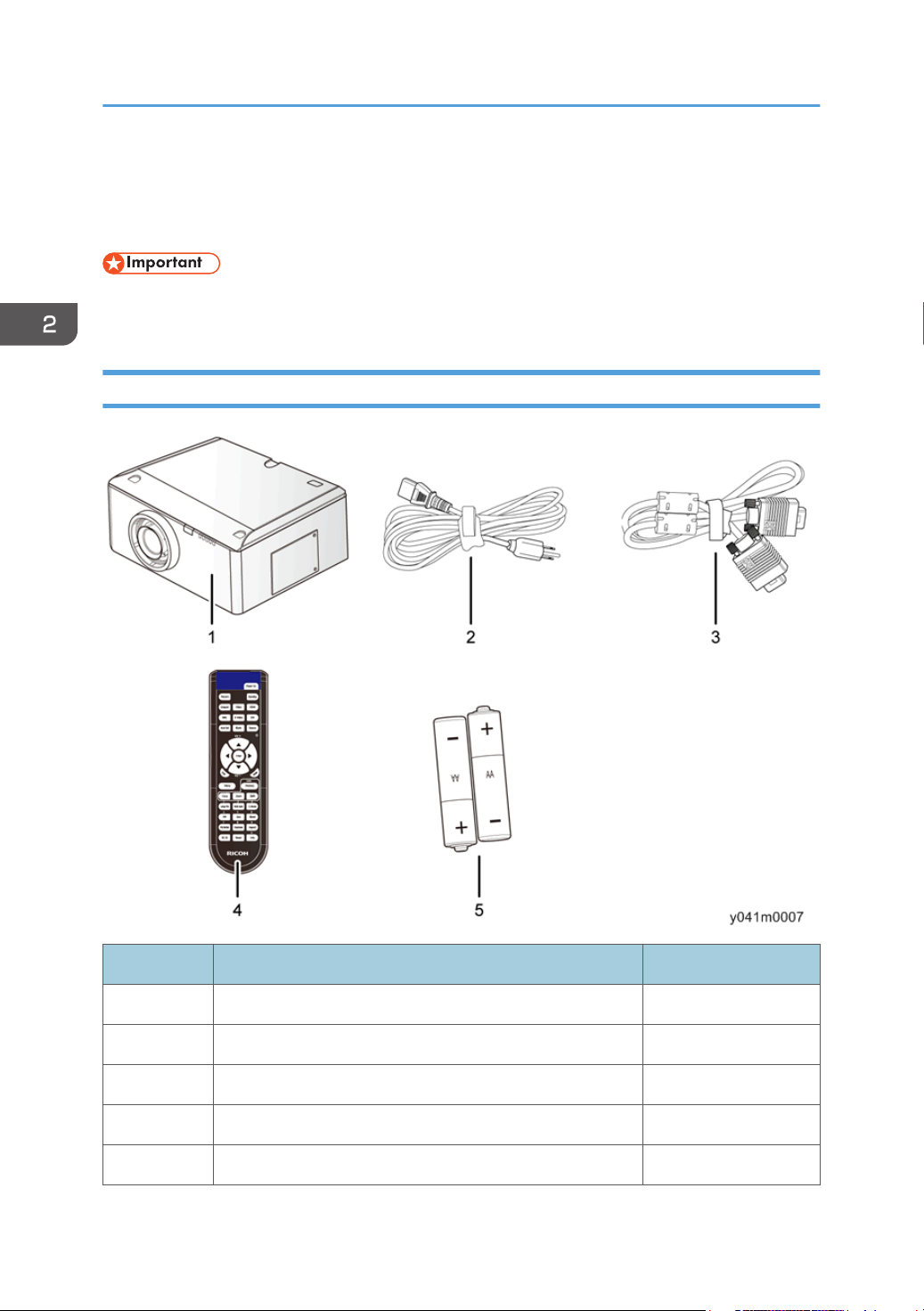
Accessory Check
24
No Description Q’ty
1 Projector with lens cover 1
2 Power cord 1
3 VGA cable 1
4 Remote control 1
5 AA (R6) batteries (for remote control) 2
Main Machine Installation
No Description Q’ty
- Documentation: User’s Manual (CD and Paper) 1
- Documentation: Warranty Card 1
• Due to different applications in each country, some regions may have different accessories.
Precautions
Please follow all warnings, precautions and maintenance as recommended in this manual.
• Do not look into the projector's lens when the lamp is on. The bright light may hurt your eyes.
• To reduce the risk of fire or electric shock, do not expose this projector to rain or moisture.
• When switching the projector off, please ensure the cooling cycle has been completed before
disconnecting power. Allow 60 seconds for the projector to cool down.
• Do not use lens cap when projector is in operation.
• Do not look into or point the laser pointer on your remote control into your or someone’s eyes.
Laser pointer can cause permanent damage to eyesight.
• Do not transport the projector with any lens installed.
Do
• Turn off and unplug the power plug from the AC outlet before cleaning the product.
• Use a soft dry cloth with mild detergent to clean the display housing.
• Disconnect the power plug from AC outlet if the product is not being used for a long period of time.
Do not
• Block the slots and openings on the unit provided for ventilation.
• Use abrasive cleaners, waxes or solvents to clean the unit.
• Use under the following conditions:
• In extremely hot, cold or humid environments.
• Ensure that the ambient room temperature is within 5°C ~ 40°C
• Relative humidity is 10% ~ 85%
25

2. Installation
• In areas susceptible to excessive dust and dirt.
• Near any appliance generating a strong magnetic field.
• In direct sunlight.
26

3. Replacement and Adjustment
Special Tools
Make sure that engineers are equipped with the following tools, which will be necessary in order to
update the firmware, and to perform adjustments that are necessary after replacing the optical engine
(page 54 "Optical Engine") or main board(page 36 "Main Board, I/O Board, LAN Board").
1. RS-232C cable (cross)
2. Laptop
3. LAN Cable
27
3. Replacement and Adjustment
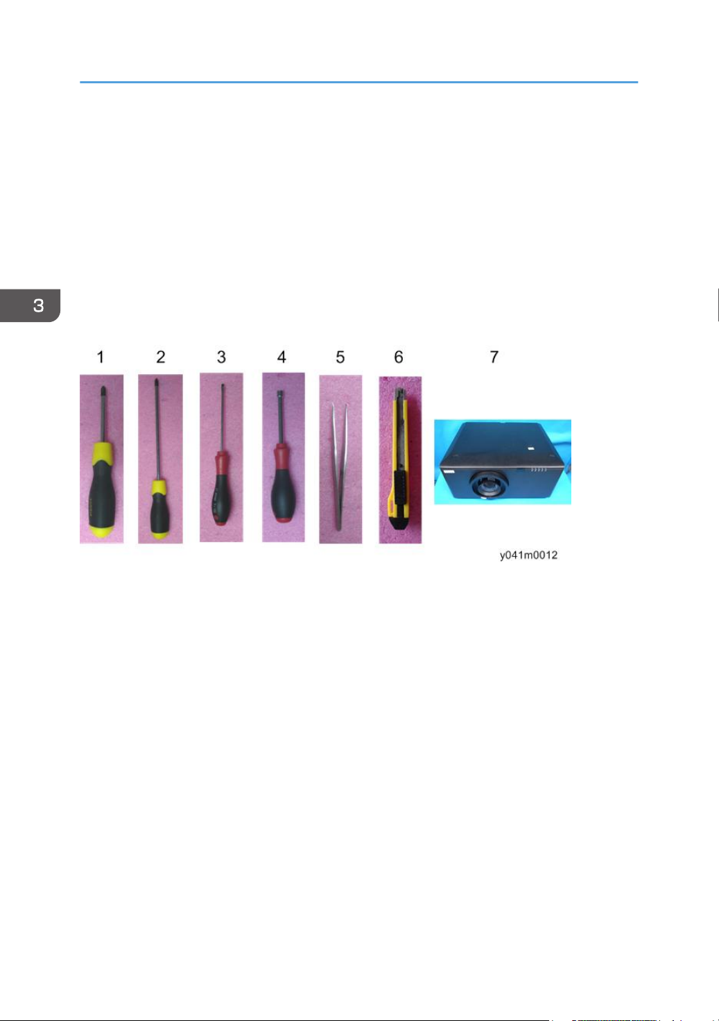
Equipment Needed
1. Screw bit (+): 105
2. Screw bit (+): 107
3. Screw bit (-): 107
4. Hex sleeves 5 mm
5. Tweezers
6. Utility knife
7. Projector
28
 Loading...