

Page 1

© 2004 Ricoh Printing Systems America, Inc.
2635-A Park Cen ter Drive
Simi Valley , C A 9 3065
October 2004
338192-001 Revision A
User’s Guide
Page 2

© 2004 Ricoh Printing Systems America, Inc. All rights reserved.
No part of this document may be reproduced without the express permission of Ricoh
Printing Sy st em s America, Inc.
The material in this document is for informational purposes and is subject to change
without notice. Ricoh Printing Systems America, Inc., assumes no responsibility for
errors or omissions in this document . No liabilit y is assumed for any damages resul ting
from the use of the information it contains.
TRADEMARK
Digital Document Publisher, DDP, DDP 70, DDP 70e, DDP 92, and their associated
logo marks are trademarks of Ricoh Printing Systems America, Inc. Ricoh and the
Ricoh word mark registered ar e trademarks of Ricoh Compan y, Ltd. All rights res erved.
All other terms and prod uct names may be trademar ks or register ed trademarks of thei r
respective owners, and are hereby acknowledged.
NOTICE TO USER
In an effort to meet t he demands of a ra pidly changing t echn ology, the manufac turer i s
continually developing new features and functions to meet your changing printing or
printer needs. As a result, this manual may not exact ly reflect future changes made to
the product. Please be sure to consult al l manual updates or addenda when using this
product’s documentation.
Page 3

Table of Contents
Introduction
About This Manual . . . . . . . . . . . . . . . . . . . . . . . . . . . . . . . . . . . . . . . . . . . . . . . . . . . . . . . . . . .vii
Audience . . . . . . . . . . . . . . . . . . . . . . . . . . . . . . . . . . . . . . . . . . . . . . . . . . . . . . . . . . . . . . .vii
Manual Conventions . . . . . . . . . . . . . . . . . . . . . . . . . . . . . . . . . . . . . . . . . . . . . . . . . . . . . viii
For More Information . . . . . . . . . . . . . . . . . . . . . . . . . . . . . . . . . . . . . . . . . . . . . . . . . . . . viii
Customer Support . . . . . . . . . . . . . . . . . . . . . . . . . . . . . . . . . . . . . . . . . . . . . . . . . . . . . . . . . . . . ix
Supplies Ordering . . . . . . . . . . . . . . . . . . . . . . . . . . . . . . . . . . . . . . . . . . . . . . . . . . . . . . . . ix
Spare Parts Ordering . . . . . . . . . . . . . . . . . . . . . . . . . . . . . . . . . . . . . . . . . . . . . . . . . . . . . . ix
Chapter 1. Printer Overview
What This Chapter Provides . . . . . . . . . . . . . . . . . . . . . . . . . . . . . . . . . . . . . . . . . . . . . . . . . . . 1-1
Printer Features . . . . . . . . . . . . . . . . . . . . . . . . . . . . . . . . . . . . . . . . . . . . . . . . . . . . . . . . . . . . . 1-2
I/O Configurations . . . . . . . . . . . . . . . . . . . . . . . . . . . . . . . . . . . . . . . . . . . . . . . . . . . . . . . 1-3
Operator Control Panel . . . . . . . . . . . . . . . . . . . . . . . . . . . . . . . . . . . . . . . . . . . . . . . . . . . 1-4
External View of the Printer (70 ppm) . . . . . . . . . . . . . . . . . . . . . . . . . . . . . . . . . . . . . . . . . . . 1-5
External View of the Printer (92ppm). . . . . . . . . . . . . . . . . . . . . . . . . . . . . . . . . . . . . . . . . . . . 1-6
Internal View of the Printer. . . . . . . . . . . . . . . . . . . . . . . . . . . . . . . . . . . . . . . . . . . . . . . . . . . . 1-7
Chapter 2. Operator Contro l Pan el
What This Chapter Provides . . . . . . . . . . . . . . . . . . . . . . . . . . . . . . . . . . . . . . . . . . . . . . . . . . . 2-1
OCP Description . . . . . . . . . . . . . . . . . . . . . . . . . . . . . . . . . . . . . . . . . . . . . . . . . . . . . . . . . . . . 2-2
Menu Structure . . . . . . . . . . . . . . . . . . . . . . . . . . . . . . . . . . . . . . . . . . . . . . . . . . . . . . . . . . . . . 2-3
Using the Menu Screens . . . . . . . . . . . . . . . . . . . . . . . . . . . . . . . . . . . . . . . . . . . . . . . . . . . . . . 2-9
Main Menu . . . . . . . . . . . . . . . . . . . . . . . . . . . . . . . . . . . . . . . . . . . . . . . . . . . . . . . . . . . 2-10
Printer Menu . . . . . . . . . . . . . . . . . . . . . . . . . . . . . . . . . . . . . . . . . . . . . . . . . . . . . . . . . . 2-11
Setup Menu . . . . . . . . . . . . . . . . . . . . . . . . . . . . . . . . . . . . . . . . . . . . . . . . . . . . . . . . . . . 2-12
Reports Menu . . . . . . . . . . . . . . . . . . . . . . . . . . . . . . . . . . . . . . . . . . . . . . . . . . . . . . . . . 2-13
Finisher Menu for the Booklet Finisher (92 ppm only) . . . . . . . . . . . . . . . . . . . . . . . . . . 2-14
Finisher Menu for the Publishing Finisher . . . . . . . . . . . . . . . . . . . . . . . . . . . . . . . . . . . 2-15
Finisher Menu for the Container Stacker . . . . . . . . . . . . . . . . . . . . . . . . . . . . . . . . . . . . 2-16
Passwords . . . . . . . . . . . . . . . . . . . . . . . . . . . . . . . . . . . . . . . . . . . . . . . . . . . . . . . . . . . . . . . . 2-17
Chapter 3. Paper Handling
What This Chapter Provides . . . . . . . . . . . . . . . . . . . . . . . . . . . . . . . . . . . . . . . . . . . . . . . . . . . 3-1
Paper . . . . . . . . . . . . . . . . . . . . . . . . . . . . . . . . . . . . . . . . . . . . . . . . . . . . . . . . . . . . . . . . . . . . . 3-2
Paper Weights . . . . . . . . . . . . . . . . . . . . . . . . . . . . . . . . . . . . . . . . . . . . . . . . . . . . . . . . . . 3-2
Unacceptable Paper . . . . . . . . . . . . . . . . . . . . . . . . . . . . . . . . . . . . . . . . . . . . . . . . . . . . . . 3-2
Storing Paper . . . . . . . . . . . . . . . . . . . . . . . . . . . . . . . . . . . . . . . . . . . . . . . . . . . . . . . . . . . 3-2
Paper Sizes, Paper Types, and Printer Input Trays . . . . . . . . . . . . . . . . . . . . . . . . . . . . . . . . . . 3-3
Table of Contents iii
Page 4

Loading Paper . . . . . . . . . . . . . . . . . . . . . . . . . . . . . . . . . . . . . . . . . . . . . . . . . . . . . . . . . . . . . . 3-4
Loading Paper in Tray 1 . . . . . . . . . . . . . . . . . . . . . . . . . . . . . . . . . . . . . . . . . . . . . . . . . . 3-4
Loading Paper in Tray 2 or 3 . . . . . . . . . . . . . . . . . . . . . . . . . . . . . . . . . . . . . . . . . . . . . . . 3-6
Loading Paper into the MBT . . . . . . . . . . . . . . . . . . . . . . . . . . . . . . . . . . . . . . . . . . . . . . . 3-8
Loading Paper into the HCF . . . . . . . . . . . . . . . . . . . . . . . . . . . . . . . . . . . . . . . . . . . . . . 3-10
Loading Special Media . . . . . . . . . . . . . . . . . . . . . . . . . . . . . . . . . . . . . . . . . . . . . . . . . . 3-11
Pre-punched Paper . . . . . . . . . . . . . . . . . . . . . . . . . . . . . . . . . . . . . . . . . . . . . . . . . . 3-11
Loading Pre-printed Paper . . . . . . . . . . . . . . . . . . . . . . . . . . . . . . . . . . . . . . . . . . . . 3-13
Loading Tab Stock . . . . . . . . . . . . . . . . . . . . . . . . . . . . . . . . . . . . . . . . . . . . . . . . . . 3-14
Setting the Custom Paper Size Values . . . . . . . . . . . . . . . . . . . . . . . . . . . . . . . . . . . . . . . . . . 3-15
Setting the Tray Adjust Values . . . . . . . . . . . . . . . . . . . . . . . . . . . . . . . . . . . . . . . . . . . . . . . . 3-15
Chapter 4. Care and Maintenance
What This Chapter Provides . . . . . . . . . . . . . . . . . . . . . . . . . . . . . . . . . . . . . . . . . . . . . . . . . . . 4- 1
Replacing Consumables . . . . . . . . . . . . . . . . . . . . . . . . . . . . . . . . . . . . . . . . . . . . . . . . . . . . . . 4-2
Adding Toner . . . . . . . . . . . . . . . . . . . . . . . . . . . . . . . . . . . . . . . . . . . . . . . . . . . . . . . . . . . 4-3
Replacing the Toner Collector Bottle . . . . . . . . . . . . . . . . . . . . . . . . . . . . . . . . . . . . . . . . 4-6
Replacing the Developer Mix . . . . . . . . . . . . . . . . . . . . . . . . . . . . . . . . . . . . . . . . . . . . . . 4-7
Exhausting the Developer Mix . . . . . . . . . . . . . . . . . . . . . . . . . . . . . . . . . . . . . . . . . . 4-7
Supplying the Developer Mix . . . . . . . . . . . . . . . . . . . . . . . . . . . . . . . . . . . . . . . . . . . 4-9
Replacing the Drum Unit . . . . . . . . . . . . . . . . . . . . . . . . . . . . . . . . . . . . . . . . . . . . . . . . . 4-12
Replacing the Fuser Cleaning Web . . . . . . . . . . . . . . . . . . . . . . . . . . . . . . . . . . . . . . . . . 4-15
Replacing Staples . . . . . . . . . . . . . . . . . . . . . . . . . . . . . . . . . . . . . . . . . . . . . . . . . . . . . . 4-17
Clearing Paper Jams . . . . . . . . . . . . . . . . . . . . . . . . . . . . . . . . . . . . . . . . . . . . . . . . . . . . . . . . 4-18
Vertical Path Cover . . . . . . . . . . . . . . . . . . . . . . . . . . . . . . . . . . . . . . . . . . . . . . . . . . . . . 4-18
Switch Back Area . . . . . . . . . . . . . . . . . . . . . . . . . . . . . . . . . . . . . . . . . . . . . . . . . . . . . . 4-19
Paper Feed Block Area . . . . . . . . . . . . . . . . . . . . . . . . . . . . . . . . . . . . . . . . . . . . . . . . . . 4-21
Trays 1, 2, and 3 . . . . . . . . . . . . . . . . . . . . . . . . . . . . . . . . . . . . . . . . . . . . . . . . . . . . . . . 4-23
Tray 1 . . . . . . . . . . . . . . . . . . . . . . . . . . . . . . . . . . . . . . . . . . . . . . . . . . . . . . . . . . . . 4-23
Tray 2 or 3 . . . . . . . . . . . . . . . . . . . . . . . . . . . . . . . . . . . . . . . . . . . . . . . . . . . . . . . . . 4-23
Multi-bypass Tray . . . . . . . . . . . . . . . . . . . . . . . . . . . . . . . . . . . . . . . . . . . . . . . . . . . . . . 4-24
High Capacity Feeder . . . . . . . . . . . . . . . . . . . . . . . . . . . . . . . . . . . . . . . . . . . . . . . . . . . 4-24
Tab Stock Jam Recovery . . . . . . . . . . . . . . . . . . . . . . . . . . . . . . . . . . . . . . . . . . . . . . . . . 4-25
Cleaning the Printer. . . . . . . . . . . . . . . . . . . . . . . . . . . . . . . . . . . . . . . . . . . . . . . . . . . . . . . . . 4-26
Cleaning the Printer Covers . . . . . . . . . . . . . . . . . . . . . . . . . . . . . . . . . . . . . . . . . . . . . . . 4-26
Cleaning the Inside of the Printer . . . . . . . . . . . . . . . . . . . . . . . . . . . . . . . . . . . . . . . . . . 4-27
Cleaning Trays 1, 2 and 3, the MBT, and HCF . . . . . . . . . . . . . . . . . . . . . . . . . . . . . . . . 4-27
Cleaning the Toner Bottle Joint . . . . . . . . . . . . . . . . . . . . . . . . . . . . . . . . . . . . . . . . . . . . 4-28
Cleaning the Conveyance Belt Area . . . . . . . . . . . . . . . . . . . . . . . . . . . . . . . . . . . . . . . . 4-28
Cleaning the Toner Collector Bottle Area . . . . . . . . . . . . . . . . . . . . . . . . . . . . . . . . . . . . 4-29
Handling and Storing Supplies and Consumables . . . . . . . . . . . . . . . . . . . . . . . . . . . . . . . . . 4-30
Paper . . . . . . . . . . . . . . . . . . . . . . . . . . . . . . . . . . . . . . . . . . . . . . . . . . . . . . . . . . . . . . . . 4-30
When Loading . . . . . . . . . . . . . . . . . . . . . . . . . . . . . . . . . . . . . . . . . . . . . . . . . . . . . . 4-30
When Storing . . . . . . . . . . . . . . . . . . . . . . . . . . . . . . . . . . . . . . . . . . . . . . . . . . . . . . 4-30
When Paper Jams Frequently Occur . . . . . . . . . . . . . . . . . . . . . . . . . . . . . . . . . . . . . 4-30
iv Table of Contents
Page 5

Toner and Developer . . . . . . . . . . . . . . . . . . . . . . . . . . . . . . . . . . . . . . . . . . . . . . . . . . . . 4-31
When Purchasing . . . . . . . . . . . . . . . . . . . . . . . . . . . . . . . . . . . . . . . . . . . . . . . . . . . 4-31
Chapter 5. Troubleshooting
What This Chapter Provides . . . . . . . . . . . . . . . . . . . . . . . . . . . . . . . . . . . . . . . . . . . . . . . . . . . 5- 1
Guidelines Flowchart . . . . . . . . . . . . . . . . . . . . . . . . . . . . . . . . . . . . . . . . . . . . . . . . . . . . . . . . 5-2
Basic Troubleshooting Tips . . . . . . . . . . . . . . . . . . . . . . . . . . . . . . . . . . . . . . . . . . . . . . . . . . . 5-3
General Printing Problems . . . . . . . . . . . . . . . . . . . . . . . . . . . . . . . . . . . . . . . . . . . . . . . . . . . . 5-4
Print Quality Problems . . . . . . . . . . . . . . . . . . . . . . . . . . . . . . . . . . . . . . . . . . . . . . . . . . . . . . . 5-4
Duplex Printing Problems. . . . . . . . . . . . . . . . . . . . . . . . . . . . . . . . . . . . . . . . . . . . . . . . . . . . . 5-4
OCP Display Messages. . . . . . . . . . . . . . . . . . . . . . . . . . . . . . . . . . . . . . . . . . . . . . . . . . . . . . . 5-5
Booklet Finisher Error Codes (Option). . . . . . . . . . . . . . . . . . . . . . . . . . . . . . . . . . . . . . . . . . 5-15
Appendix A. Safety Information
General . . . . . . . . . . . . . . . . . . . . . . . . . . . . . . . . . . . . . . . . . . . . . . . . . . . . . . . . . . . . . . . . . . .A-1
Laser Safety. . . . . . . . . . . . . . . . . . . . . . . . . . . . . . . . . . . . . . . . . . . . . . . . . . . . . . . . . . . . . . . .A-1
Certifications. . . . . . . . . . . . . . . . . . . . . . . . . . . . . . . . . . . . . . . . . . . . . . . . . . . . . . . . . . . . . . .A-3
FCC Notice . . . . . . . . . . . . . . . . . . . . . . . . . . . . . . . . . . . . . . . . . . . . . . . . . . . . . . . . . . . .A-3
Canadian Certification . . . . . . . . . . . . . . . . . . . . . . . . . . . . . . . . . . . . . . . . . . . . . . . . . . . .A-3
VCCI Notice (Japan) . . . . . . . . . . . . . . . . . . . . . . . . . . . . . . . . . . . . . . . . . . . . . . . . . . . . .A-3
Declaration of Conformity . . . . . . . . . . . . . . . . . . . . . . . . . . . . . . . . . . . . . . . . . . . . . . . . .A-4
70 ppm . . . . . . . . . . . . . . . . . . . . . . . . . . . . . . . . . . . . . . . . . . . . . . . . . . . . . . . . . . . . .A-4
92 ppm . . . . . . . . . . . . . . . . . . . . . . . . . . . . . . . . . . . . . . . . . . . . . . . . . . . . . . . . . . . . .A-5
When Installing and Relocating the Printer . . . . . . . . . . . . . . . . . . . . . . . . . . . . . . . . . . . . . . .A-7
Power Specifications . . . . . . . . . . . . . . . . . . . . . . . . . . . . . . . . . . . . . . . . . . . . . . . . . . . . .A-7
Power Cords . . . . . . . . . . . . . . . . . . . . . . . . . . . . . . . . . . . . . . . . . . . . . . . . . . . . . . . . . . .A-7
Positioning the Printer Safely . . . . . . . . . . . . . . . . . . . . . . . . . . . . . . . . . . . . . . . . . . . . . . . . . .A-9
Environmental Limit . . . . . . . . . . . . . . . . . . . . . . . . . . . . . . . . . . . . . . . . . . . . . . . . . . . . .A-9
Operating Precautions . . . . . . . . . . . . . . . . . . . . . . . . . . . . . . . . . . . . . . . . . . . . . . . . . . . . . . .A-10
VORSICHTSMASSNAHMEN BEIM BETRIEB . . . . . . . . . . . . . . . . . . . . . . . . . . . . .A-10
SAFETY PRECAUTIONS . . . . . . . . . . . . . . . . . . . . . . . . . . . . . . . . . . . . . . . . . . . . . . .A-11
SICHERHEITSVORKEHRUNGEN . . . . . . . . . . . . . . . . . . . . . . . . . . . . . . . . . . . . . . .A-11
Care of Printer Supplies . . . . . . . . . . . . . . . . . . . . . . . . . . . . . . . . . . . . . . . . . . . . . . . . . . . . .A-13
Chapter 6. Web Utilities
Features . . . . . . . . . . . . . . . . . . . . . . . . . . . . . . . . . . . . . . . . . . . . . . . . . . . . . . . . . . . . . . . . . . .B-1
Web Utilities Access. . . . . . . . . . . . . . . . . . . . . . . . . . . . . . . . . . . . . . . . . . . . . . . . . . . . . . . . .B-1
Web Site Layout . . . . . . . . . . . . . . . . . . . . . . . . . . . . . . . . . . . . . . . . . . . . . . . . . . . . . . . . . . . .B-2
Using the Web Utilities. . . . . . . . . . . . . . . . . . . . . . . . . . . . . . . . . . . . . . . . . . . . . . . . . . . . . . .B-3
Appendix B . Specifications
What This Appendix Contains . . . . . . . . . . . . . . . . . . . . . . . . . . . . . . . . . . . . . . . . . . . . . . . . .C-1
Specifications . . . . . . . . . . . . . . . . . . . . . . . . . . . . . . . . . . . . . . . . . . . . . . . . . . . . . . . . . . . . . .C-2
Base Printer . . . . . . . . . . . . . . . . . . . . . . . . . . . . . . . . . . . . . . . . . . . . . . . . . . . . . . . . . . . . C-2
Table of Contents v
Page 6

I/O Configurations . . . . . . . . . . . . . . . . . . . . . . . . . . . . . . . . . . . . . . . . . . . . . . . . . . . . . . .C-3
Consumables . . . . . . . . . . . . . . . . . . . . . . . . . . . . . . . . . . . . . . . . . . . . . . . . . . . . . . . . . . .C-3
Appendix C . P aper Specificat i ons
Media Guidelines . . . . . . . . . . . . . . . . . . . . . . . . . . . . . . . . . . . . . . . . . . . . . . . . . . . . . . . . . . .D-1
General Media Recommendations . . . . . . . . . . . . . . . . . . . . . . . . . . . . . . . . . . . . . . . . . . .D-1
Paper Specifications . . . . . . . . . . . . . . . . . . . . . . . . . . . . . . . . . . . . . . . . . . . . . . . . . . . . .D-2
Paper Weight . . . . . . . . . . . . . . . . . . . . . . . . . . . . . . . . . . . . . . . . . . . . . . . . . . . . . . . . . . .D-3
Paper Color . . . . . . . . . . . . . . . . . . . . . . . . . . . . . . . . . . . . . . . . . . . . . . . . . . . . . . . . . . . .D-3
Paper Composition . . . . . . . . . . . . . . . . . . . . . . . . . . . . . . . . . . . . . . . . . . . . . . . . . . . . . .D-4
Paper Cut . . . . . . . . . . . . . . . . . . . . . . . . . . . . . . . . . . . . . . . . . . . . . . . . . . . . . . . . . . . . . .D-4
Paper Friction . . . . . . . . . . . . . . . . . . . . . . . . . . . . . . . . . . . . . . . . . . . . . . . . . . . . . . . . . .D-4
Paper Smoothness . . . . . . . . . . . . . . . . . . . . . . . . . . . . . . . . . . . . . . . . . . . . . . . . . . . . . . .D-5
Paper Fusing . . . . . . . . . . . . . . . . . . . . . . . . . . . . . . . . . . . . . . . . . . . . . . . . . . . . . . . . . . .D-5
Moisture . . . . . . . . . . . . . . . . . . . . . . . . . . . . . . . . . . . . . . . . . . . . . . . . . . . . . . . . . . . . . . .D-5
Paper Curl . . . . . . . . . . . . . . . . . . . . . . . . . . . . . . . . . . . . . . . . . . . . . . . . . . . . . . . . . . . . .D-6
How to Avoid Paper Curl . . . . . . . . . . . . . . . . . . . . . . . . . . . . . . . . . . . . . . . . . . . . . .D-6
Recycled Paper . . . . . . . . . . . . . . . . . . . . . . . . . . . . . . . . . . . . . . . . . . . . . . . . . . . . . . . . .D-7
Grain Direction . . . . . . . . . . . . . . . . . . . . . . . . . . . . . . . . . . . . . . . . . . . . . . . . . . . . . . . . .D-7
Paper Smoothness . . . . . . . . . . . . . . . . . . . . . . . . . . . . . . . . . . . . . . . . . . . . . . . . . . . . . . .D-7
Special Media . . . . . . . . . . . . . . . . . . . . . . . . . . . . . . . . . . . . . . . . . . . . . . . . . . . . . . . . . . . . . .D-8
Preprinted Paper . . . . . . . . . . . . . . . . . . . . . . . . . . . . . . . . . . . . . . . . . . . . . . . . . . . . . . . .D-8
Ink Recommendations . . . . . . . . . . . . . . . . . . . . . . . . . . . . . . . . . . . . . . . . . . . . . . . . .D-9
Paper Curl in Preprinted Paper . . . . . . . . . . . . . . . . . . . . . . . . . . . . . . . . . . . . . . . . . .D-9
Prepunched Paper . . . . . . . . . . . . . . . . . . . . . . . . . . . . . . . . . . . . . . . . . . . . . . . . . . . . . .D-10
Adhesive Labels . . . . . . . . . . . . . . . . . . . . . . . . . . . . . . . . . . . . . . . . . . . . . . . . . . . . . . .D-11
Adhesive Label Configuration . . . . . . . . . . . . . . . . . . . . . . . . . . . . . . . . . . . . . . . . .D-12
Storing Labels . . . . . . . . . . . . . . . . . . . . . . . . . . . . . . . . . . . . . . . . . . . . . . . . . . . . . .D-12
Adhesive Label Specifications . . . . . . . . . . . . . . . . . . . . . . . . . . . . . . . . . . . . . . . . .D-13
Perforated Paper . . . . . . . . . . . . . . . . . . . . . . . . . . . . . . . . . . . . . . . . . . . . . . . . . . . . . . .D-14
Tab Stock . . . . . . . . . . . . . . . . . . . . . . . . . . . . . . . . . . . . . . . . . . . . . . . . . . . . . . . . . . . . .D-15
Transparencies . . . . . . . . . . . . . . . . . . . . . . . . . . . . . . . . . . . . . . . . . . . . . . . . . . . . . . . . .D-15
Printing Guidelines . . . . . . . . . . . . . . . . . . . . . . . . . . . . . . . . . . . . . . . . . . . . . . . . . . . . . . . . .D-16
Printable Area . . . . . . . . . . . . . . . . . . . . . . . . . . . . . . . . . . . . . . . . . . . . . . . . . . . . . . . . .D-16
Preprinted Lines . . . . . . . . . . . . . . . . . . . . . . . . . . . . . . . . . . . . . . . . . . . . . . . . . . . . . . . .D-16
Index
vi Table of Contents
Page 7

About This Manual
This manual provides easy access to the information you need to operate the 70 PPM or
92 PPM (Pages Per Minute) laser printer.
NOTE:
This User’s Guide is intended to be viewed online. When viewing it online,
use the bookmarks and page reference links for easy navigation
throughout the do c ume n t .
To find out about a specific topic, refer to:
n
Chapter 1: Printer Overview – For printer components and features.
n
Chapter 2: Operator Control Panel – To access and use the liquid crystal display
(LCD) window and the menus screens.
n
Chapter 3: Paper Handling – For media recommendations and paper handling
procedures.
n
Chapter 4: Care and Maintenance – For detailed instructions on replacing
consumables, clearing paper jams, and cleaning and maintaining the printer.
Introduction
Audience
This manual is written for those persons responsible for operating the printer. A basic
understanding of computer equipment and its operations is required.
n
Chapter 5: Troubleshooting – For information on printing problems and printer
error and warning messages.
n
Chapter 6: Web Utilities – For information on accessing the printer via the
Internet or your company’s Intranet.
n
Appendix A: Safety Information – For safety information and printer
characteristics, including environmental and electrical requirements.
n
Appendix B: Specifications – For printer specifications.
n
Appendix C: Paper Specifications – For media specifications and printing
guidelines.
n
Glossary – For definitions of terms and acronyms.
n
Index – For specific page references.
Introduction vii
Page 8

Manual Conventions
The following conventions are used in this manual:
n
Bold and Italics are used sparingly for emphasis.
n
Informa tion you enter: Looks Like This.
n
Key Names (or Labels): Look Like This.
n
System messages: Look Like This.
n
Variable user information: Looks Like This.
Pay particular attention to Notes, Cautions, and Warnings. These alert you to critical
information, as follows:
NOTE:
Provides important additional information.
CAUTION!
Alerts you to an operating procedure, practi ce, or condition that, i f not
strictly observed, might result in damage to the equipment.
WARNING!
Alerts you to an operating procedure, practi ce, or condition that, i f not
strictly observed, can result in safety hazards to personnel, severe injury,
or loss of life.
For More Information
Refer to the following related documents for more details about your printer.
n
Read Me First
n
Unpacking and Setup In structions
n
Engine Ma int e n c e Ma nu al
n
Controller Maintence Manual
n
Illustrated Parts List (IPL)
viii Introduction
Page 9

Customer Suppor t
For technical support and other printer information, call:
n
U.S. and Canada
r
Technical Services: Contact your local Company Representative
or Distributor
r
On-Site Rep ai r S erv i c es: 800- 88 7-8848
r
Depot Repair Services: 888-372-6659 (pr ess 1, 4)
r
Web Site: http://www.rpsa.ricoh.com
r
Europe: 011 353-1-803-6500
n
Or, your local Company Representative or Distributor.
Supplies Or dering
For ordering printer supplies, call:
n
U.S. or Can ada: 888-372-6659 (pr ess 1, 1)
n
Europe: 011 353-1-803-6500
n
Australi a or New Zealand: 011 61 2-9451-3533
n
Singapore: 011 65-741-8948
n
Or, your local Company Representative or Distributor.
Spare Parts Orderin g
Contact your local Company Representative or Distributor.
Introduction ix
Page 10

x Introduction
Page 11

What This Chapter Provides
This chapter describes the parts and functions of the printer.
n
Printer Features
n
I/O Configurations
n
Operator Control Panel
n
Printer Views
Chapter 1
Printer Overview
Printer Overview 1-1
Page 12

Printer Features
The printer is a high-speed, shared-use laser printer for a 400K/month printing
environment. It incorporates a wide variety of features:
n
High-Speed and High-Quality Printing.
r
Print speed is up to 70 or 92 pages per minute (ppm), A4/Letter (Simplex)
depending on the pri nter model.
r
The printing outp ut i s at a reso lut i o n of 60 0 do t s per i nch (dpi), assur i ng
razor-sharp graphic and text output, even at very small point sizes.
n
Flexible Paper Source and Delivery.
Paper Source:
r
Standard – Two 500-sheet universal paper trays and on e 2000-shee t universal
paper cassette.
r
Standard – 150-sheet capacity Multi-bypass Tray (MBT) for automatically
printing small jobs, or manually feeding single sheets (including
transparencies, labels, and odd-sized print media).
r
Option – High Capacity Feeder with 3000-sheet capacity.
r
Option - 200-sheet universal paper Inserter (92 ppm only).
Paper Delivery - 70 ppm:
r
Option – Simple output tray with 500-sheet capacity
r
Option – Advanced Finisher with stapling and collating capabilities, and
2,000-sheet capacity (70 ppm only).
r
Option – Container Stacker with 1,500 to 6,000-sheet capacity and stacking
capability.
r
Option – Publishing Finisher with folding, stap ling, and trimming capabilities
for creating booklets.
Paper Delivery - 92 ppm:
r
Standard - One 500 sheet tray.
r
Standar d - 2,500-sh eet (Elevator Tray), 200-sh eet (Upper Tray) capacity
Finisher.
r
Option - 2,500-sheet (Elevator Tray), 200-sheet (Upper Tray), 20-set
(Booklet) capacity Booklet Finisher with folding and stapling for booklets.
r
Option – Container Stacker with 1,500 to 6,000-sheet capacity and stacking
capability.
r
Option – Publishing Finisher with folding, stap ling, and trimming capabilities
for creating booklets.
n
Multiple Original Printing (MOP) – for printing of multiple collated document
sets without multiple file transfers. Processes PCL and PostScript jobs once,
stores the images on disk, and prints each set from disk (after the first set).
1-2 Printer Overview
Page 13

n
V irtual Printer T echnology® (VPT) – allows a single printer to offer print services,
or virtual printers, each of which is configured by the Network Administrator.
n
Web Utilities – for remote access to the printer through the Internet or your
company’s Intrane t.
n
Ergonomic operat ion.
r
The easy-to-read display clearly shows the operational status of the printer.
n
Component-based con sumables.
r
User replaceable toner and staples.
n
High-volu me pr i nti ng .
r
Three standard paper cassettes with approximately 3000-sheet capacity total
and the Multi-bypass Tray (MBT) with a 150-sheet capacity.
r
Optional High Capacity Feeder (HCF) adds up to 3000 additional sheets.
r
Together they allow continuous printing of up to 6150 sheets.
n
Support s a wide-range of media types (copi er, bond, letterhead, special
application, recycled, overhead transparencies, labels) and sizes. See “Paper” on
page 3-2 for more information.
n
Printer Language Support.
r
Optional PostScript Level III (Adobe) printer language.
r
PCL5e and PCL XL prin te r l ang ua g e.
r
TIFF and PDF printer language
n
Network.
r
Ethernet 10/10 0 Bas e -T.
n
Network Protocol.
r
TCP/IP and LPR/LPD with onboard network.
r
TCP/IP, LPR/LPD, NetWare IPX, SPX, Ethertalk, NetBEUI, and DLC/LLC
with optional PSM card.
r
IPP
n
Easy installation of additional fonts and macros using the PCL Startup File.
I/O Configurations
n
Bi-directional 1284C Parallel interface with Compatibility, Nibble, Byte, and
ECP Mode support.
n
Ethernet 10/100 Base-T.
Printer Overview 1-3
Page 14

Operator Control Panel
The Operator Control Panel (OCP) is your physical interface to the printer’s features
and functions. From the control panel, you can monitor the printer’s operating status
and configure the specific printer functions.
See Chapter 2 for detailed information about the OCP.
1-4 Printer Overview
Page 15
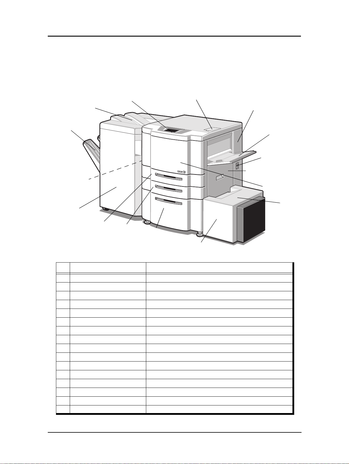
External View of the Printer (70 ppm )
The following illustration shows the printer with an Advanced Finisher and High
Capacity Feeder installed. Refer to your option-specific User’s Guide for details on
other dev ices.
16. Upper Tray
11. Elevator Tray
10. Switch Back Cover
(Not Shown)
15. Advanced Finisher
9. Tray 3
Panel
8. Tray 2
5. Toner Supply Cover6. Operator Control
14. Toner Collector
Bottle Cover
4. Multi-bypass Tray
1. Power Switch
3. Vertical Path Cover
2. Front Cover
13. HCF Top
Cover
7. Tray 1
12. High Capacity Feeder
Key Component Description
1 Power Switch Press to turn the printer on and off.
2 Front Cover Open to replace units, clear paper jams, or clean the printer.
3 Vertical Path Cover Open to clear paper jams.
4 Multi-bypass Tray (MBT) Holds up to 150 sheets of paper.
5 Toner Supply Cover Open to replenish the toner supply.
6 Operator Control Panel (OCP) Displays printer status and menu information.
7 Tray 1 Holds up to 2000 sheets of paper.
8 Tray 2 Holds up to 500 sheets of paper.
9 Tray 3 Holds up to 500 sheets of paper.
10 Switch Back Cover Open to clear paper jams.
11 Elevator Tray Output tray of the Advanced Finisher.
12 High Capacity Feeder (HCF) Option. Holds up to 3000 sheets of paper.
13 HCF Top Cover Open to clear paper jams in the High Capacity Feeder.
14 Toner Collector Bottle Cover Open to replace the toner collector bottle.
15 Advanced Finisher Option. For stacking, job offset, and stapling.
16 Upper Tray Output tray of the Advanced Finisher.
Printer Overview 1-5
Page 16
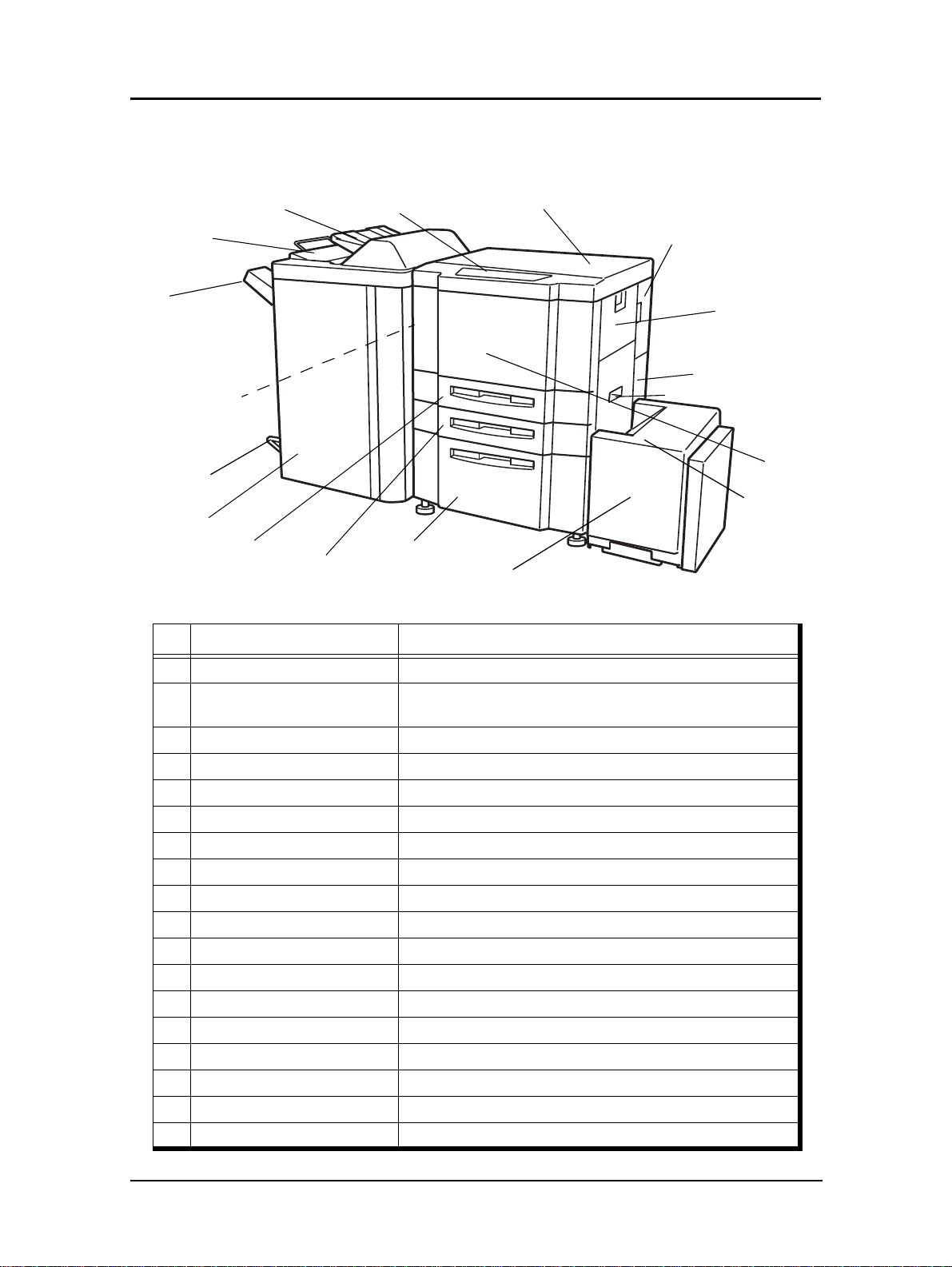
External View of the Printer (9 2ppm)
16. Upper Tray
6. Operator Control
17. Cover Sheet
Feeder
11. Elevator Tray
10. Switch Back Cover
(Not Shown)
18. Booklet Tray
15. Finisher
9. Tray 3
8. Tray 2
Key Component Description
Panel
7. Tray 1
5. Toner Supply Cover
12. High Capacity Feeder
14. Toner Collector
Bottle Cover
4. Multi-bypass Tray
1. Power Switch
3. Vertical Path Cover
2. Front Cover
13. HCF Top
Cover
1 Power Switch Press to turn the printer on and off.
2 Front Cover
3 Vertical Path Cover Open to clear paper jams.
4 Multi-bypass Tray (MBT) Holds up to 150 sheets of paper.
5 Toner Supply Cover Open to replenish the toner supply.
6 Operator Control Panel (OCP) Displays printer status and menu information.
7 Tray 1 Holds up to 2,000 sheets of paper.
8 Tray 2 Holds up to 500 sheets of paper.
9 Tray 3 Holds up to 500 sheets of paper.
10 Switch Back Cover Open to clear paper jams.
11 Elevator Tray Output tray.
12 High Capacity Feeder (HCF) Holds up to 3,000 sheets of paper.
13 HCF Top Cover Open to clear paper jams.
14 Toner Collector Bottle Cover Open to replace the toner collector bottle.
15 Finisher For stacking, job offset, and stapling.
16 Upper Tray Output tray .
17 Cover Sheet Feeder Holds cover sheet or insert paper.
18 Booklet Tray Output tray for the Booklet Finisher.
Open to replace units, clear paper jams, or cl ean the inside of
the printer.
1-6 Printer Overview
Page 17
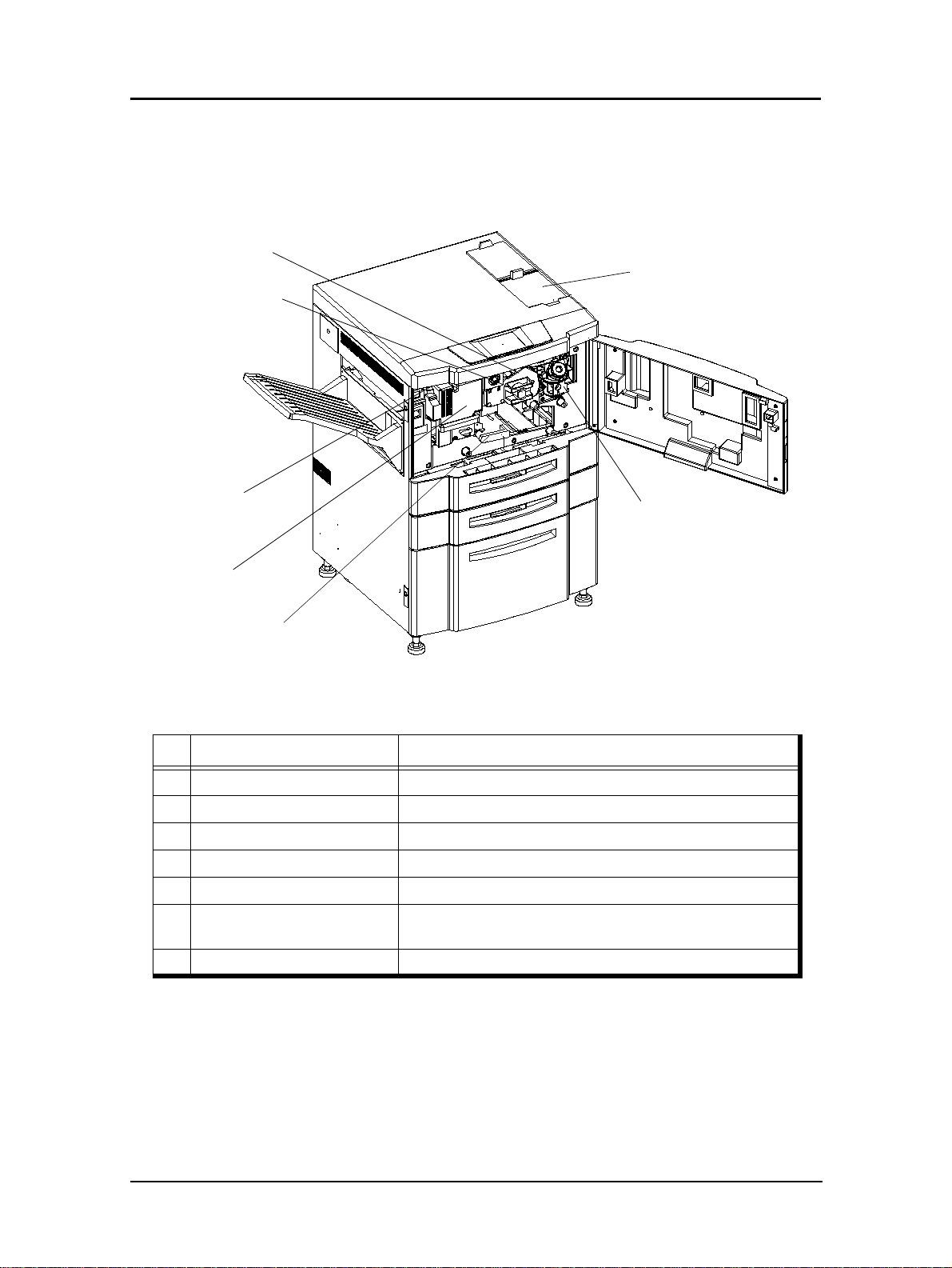
Internal View of the Printer
3. Drum Unit
2. Drum Center Lock
4. Fuser Latch
5. Fuser Unit
1. Toner Hopper Unit
6. Developer Duct
7. TH Handle
Key Component Description
1 Toner Hopper Unit Install the toner bottle here.
2 Drum Center Lock Holds the drum in place.
3 Drum Unit OPC drum.
4 Fuser Latch Provides access to the fuser unit.
5 Fuser Unit Fuses the toner on the paper.
6 Developer Duct
7 TH Handle Handle of the toner transfer unit.
Mount the developer bot tle onto th e devel op er du ct to repla ce
consumed developer.
Printer Overview 1-7
Page 18

1-8 Printer Overview
Page 19

What This Chapter Provides
This chapter contains information on the following topics.
n
OCP Description
n
Menu Structure
n
Using the Menu Screens
n
Passwords
Chapter 2l
Operator Control Panel
Operator Control Panel 2-1
Page 20
OCP Description
The Operator Control Panel (OCP) is a touch panel display that you use to set up print
options and monitor job and printer status. It is also used by the Network Administrator
to configure the printer and by the Service Technician to perform maintenance on the
printer.
Operator Control Panel
2-2 Operator Control Panel
Page 21
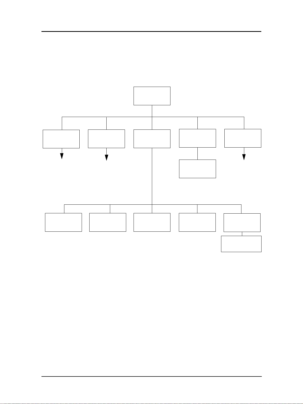
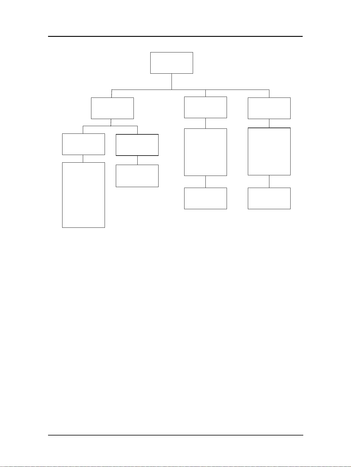
Menu Structure
The OCP menu is structured as shown in the following flowcharts. Each box in the
chart represents an OCP display screen. Use this flowchart to assist you in setting print
job options.
Main Menu
Printer Menu
Continued on
page 2-4
Setup Menu
Continued on
page 2-5
Reports Menu
Jobs Menu
Cancel Printing
Disk DirectorySummaryDemoStatus
Finisher Menu
Continued on
page 2-7
Fonts
• PCL Fonts
• PostScript Fonts
1
2
1
The Finisher Menu is only displayed when a finisher is installed.
2
Available when PostScript is installed.
Operator Control Panel 2-3
Page 22
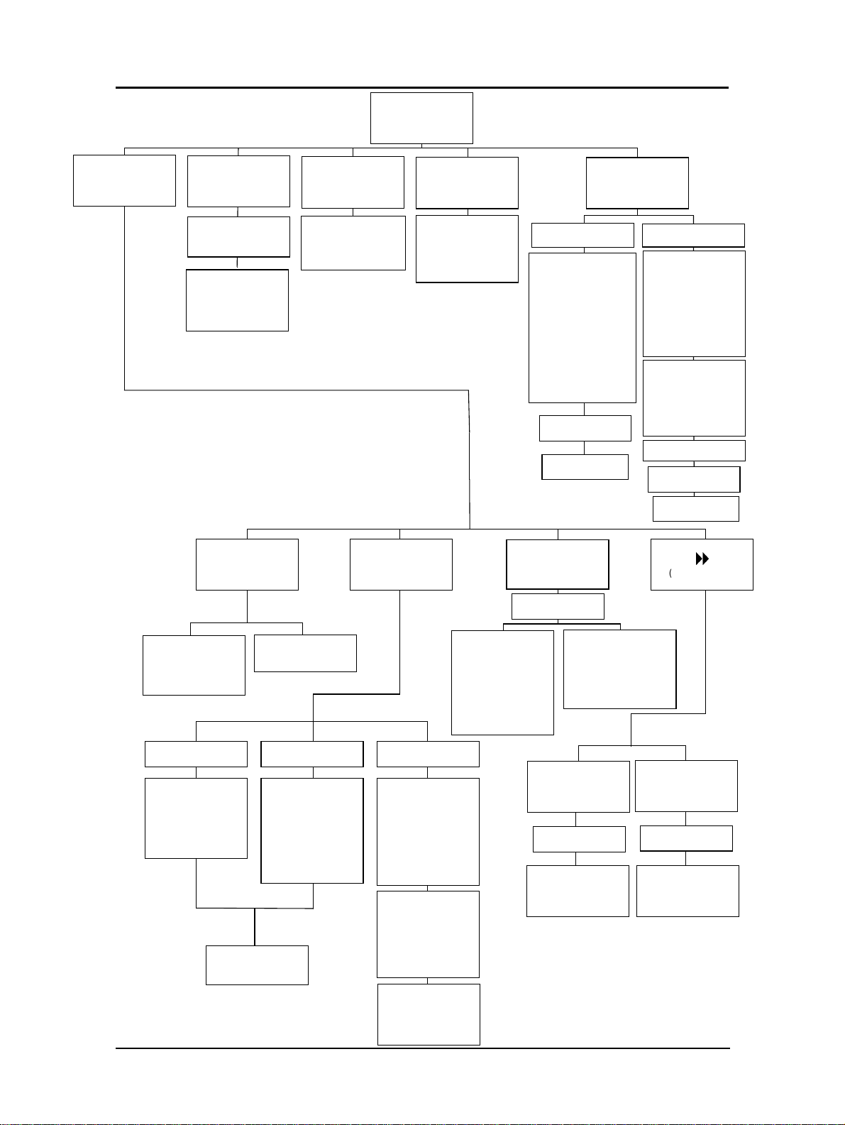
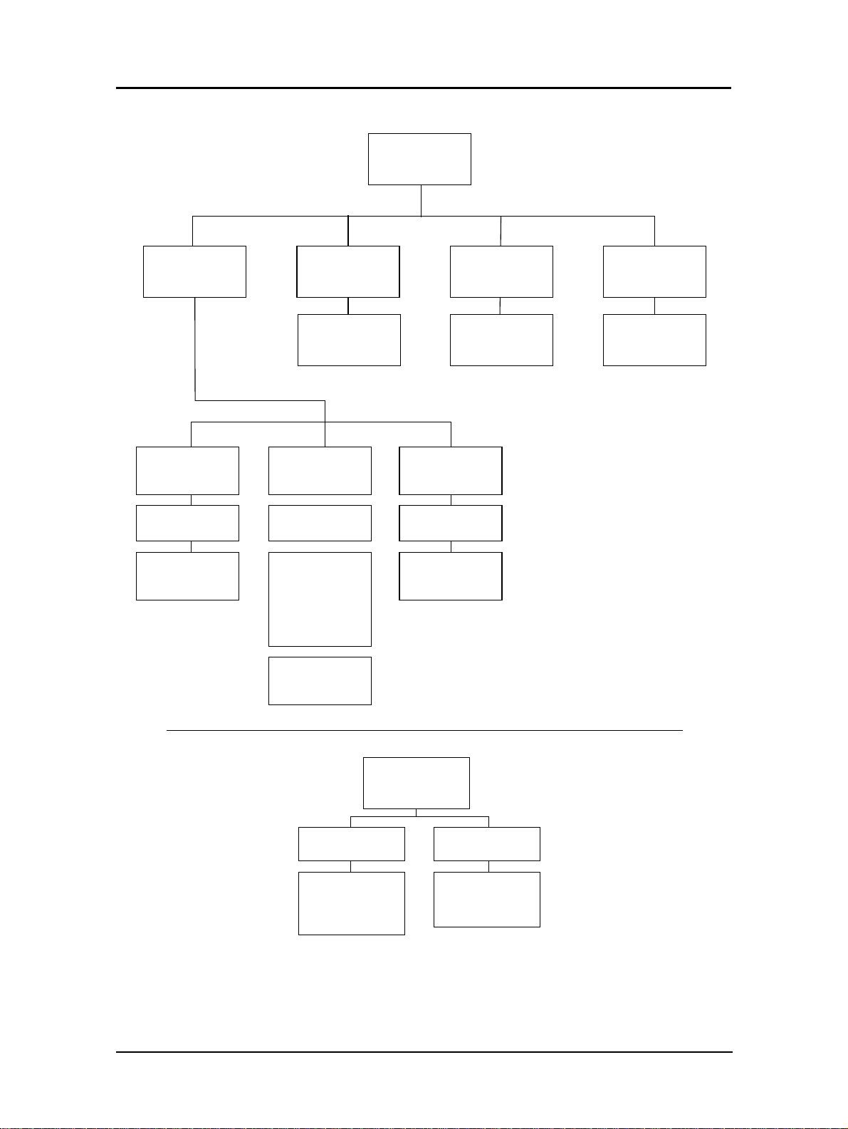
Prin ter Menu
Paper
Source
Default
Output
• Upper Tray
• Elevator Tray
• Stacker 5
• Stacker 6
• Stacker 7
• Stacker 8
4
4
4
4
Default
Options
• Jam Recovery
• Wait Timeout
• Duplex-Always
Paper Size
PostScript
• Print Errors
• Best Fit
• Job Timeout
• Halftone
1
Print Quality
• Solid Black
• Sq uareBlk/Skew
• Half Ton e
• GhostG
• Jitter
• Large Letters
• Diagonal Lines
• Density Scale
• Small to Large
• Text File 4%
• Cross Pattern
Paper Type
Select Paper
Source
Select Paper
Output
Test Print
Finishing Test
• Staple:Front
• Staple:Rear
• Staple:Booklet
• Jogging
• Center Fold
• Saddle Stitch
• Inserter
• Inserter1
• Inserter2
• Center Fold
• Saddle Stich
• Trimming
• Jogging
2
3
3
4
Select Paper
Source
Select Paper
Output
8
(More Options)
7
2
2
3
3
4
• AutoSelect
• 1
• 2
• 3
Tray 1
6
• Folio SEF
• Super B SEF
• Letter Tab LEF
• A4 Tab LEF
• Custom Size
• Letter SEF
• A4 SEF
• MBT
• HCF
Trays 2, 3
6
• Folio SEF
• Super B SEF
• Statement SEF
• Custom Size
• LetterTab LEF
• A4 Tab LEF
• Executive LEF
• Plain
• Bond
• Color
• Label
• Letterhead
• Preprinted
• Prepunched
MBT
MBT
• Letter LEF
• Letter SEF
• Ledger SEF
• Executive LEF
• Folio SEF
• Legal SEF
• Statement SEF
• A4 LEF
• A4 SEF
• A3 SEF
• A5 SEF
• B5 LEF
• B4 SEF
• Super B SEF
• Letter Tab LEF
• A4 Tab LEF
• Custom Size
Select Paper
Source
• Recycled
• Special
5
• Transparency
• Transparency-pp
5
5
• Other
Paper Weight
Select Paper
Source
Paper Weight
Settings
1
Available when PostScript is installed.
2
Available when the Booklet Finisher is installed.
3
Available when the Publishing Finisher is installed
4
Available when the Container Stacker is installed.
5
Available when MBT is selected.
6
Available when the sensor plate in the tray is set to
the first position.
7
Available with the 92 ppm printer.
Tray Adjust
Select Paper
Source
Tray Adjust
Settings
2-4 Operator Control Panel
Page 23
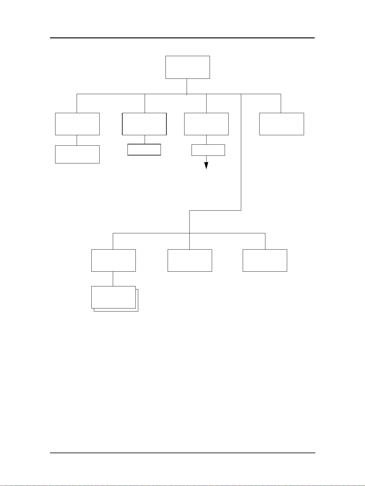
Setup Menu
OCP
• Brightness
• Contrast
Developer Mix
• Exhaust
• Supply
Service
Password
1
Password
Continued on
page 2-6
Drum Unit
ConsumablesSystem
Fuser Web
1
Service menu items are for Serv ice Technicians only and are not discussed in this manu al.
Operator Control Panel 2-5
Page 24
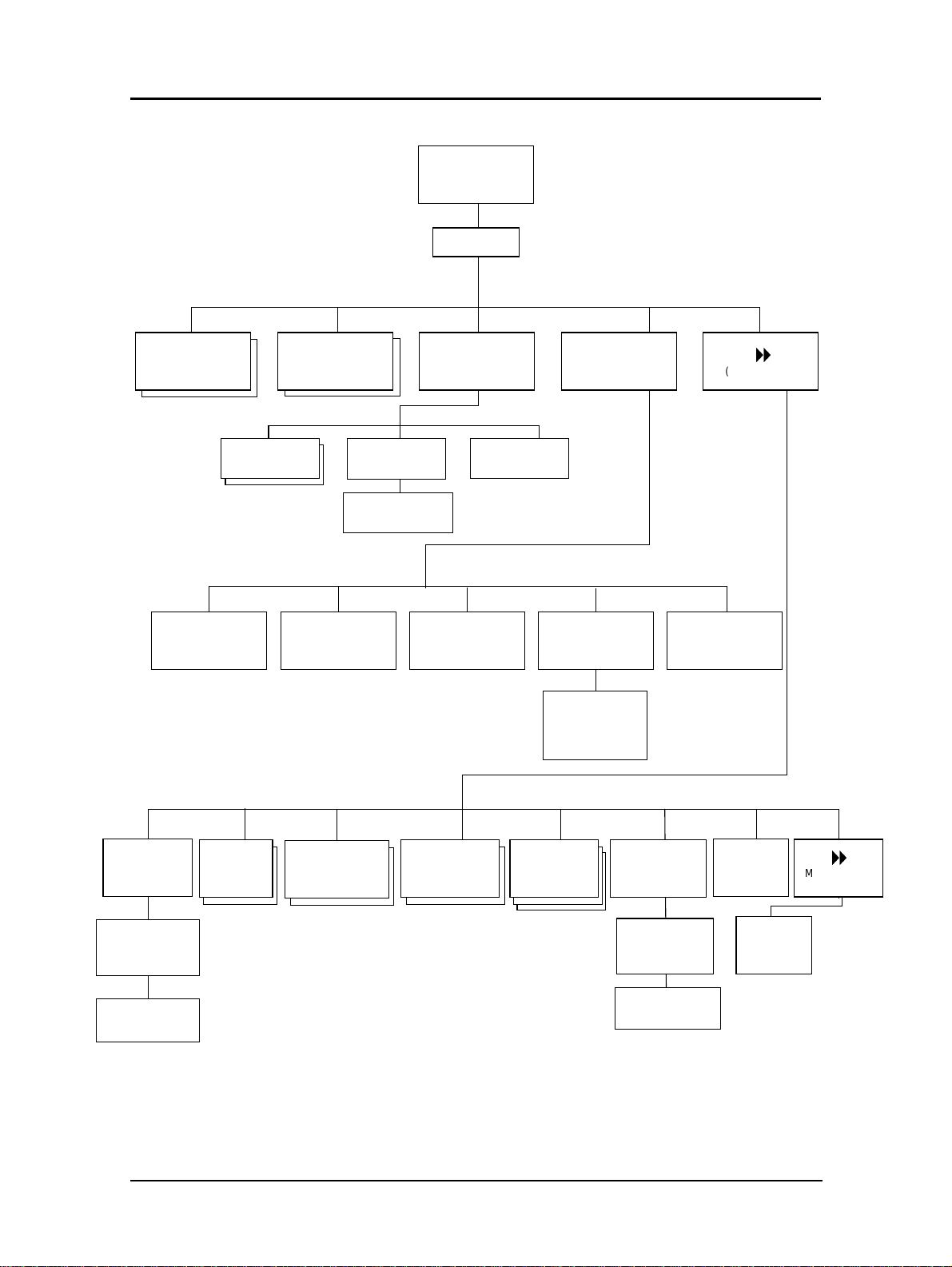
System
Password
Reset
Ack Pulse
Width
Software
Log
Subnet MaskIP Address
Mode
• Compatible
• Bi-Directional
Parallel Network
Capture to
File
Gateway
Boot Method
Address
• AutoSelect
• DHCP
• RARP
• STATIC
1
8
(More Options)
HTTP Port
1
Calendar
Country
Code
• Time Zone
• Date
• Time
Time Zone
Options
1
Available with the optional Network Interface Card only.
2
Available when Energy Save Mode is enabled.
Energy
Save Mode
2-6 Operator Control Panel
Energy2
Save Time
Password
Emulation
• AutoSel ec t
• PostScr i pt
• PCL
PostScript
Options
public
R/W
Auto
Online
8
(More O pt i ons)
Page 25
Finisher
1,2
Paper Size
• Letter LEF
• Letter SEF
• Ledger SEF
• Legal SEF
• A4 LEF
• A4 SEF
• A3 SEF
• B5 LEF
• B4 SEF
• Custom Size
Inserter
Paper Weight
Paper Weight
Settings
Stapler
• Letter SEF
• B4 SEF
• A4 SEF
• A3 SEF
• Legal SEF
• Ledger SEF
• Other
Position
Folder
• Letter SEF
• B4 SEF
• A4 SEF
• A3 SEF
• Legal SEF
• Ledger SEF
• Other
Position
1
92 ppm only.
2
Available when the Booklet Finisher is installed.
Operator Control Panel 2-7
Page 26
Finis her Me nu
1
Stapler TrimmerInserter
Position Position
Paper Size Paper Type Paper Weight
Select
Inserter Tray
• Folio SEF
• SuperB SEF
• Custom Size
Select
Inserter Tray
• Plain
• Bond
• Color
• Letterhead
• Preprinted
• Prepunched
• Recycled
• Special
• Other
Select
Inserter Tray
Paper Weight
Settings
Folder
Position
Short Stacking
• 5
• 6
• 7
• 8
1
Available when the Publishing Finisher is installed.
2
Avalable when the Container Stacker is installed.
2-8 Operator Control Panel
Finisher Menu
• AutoSelect
• Enable
• Disable
2
Decurler
Page 27
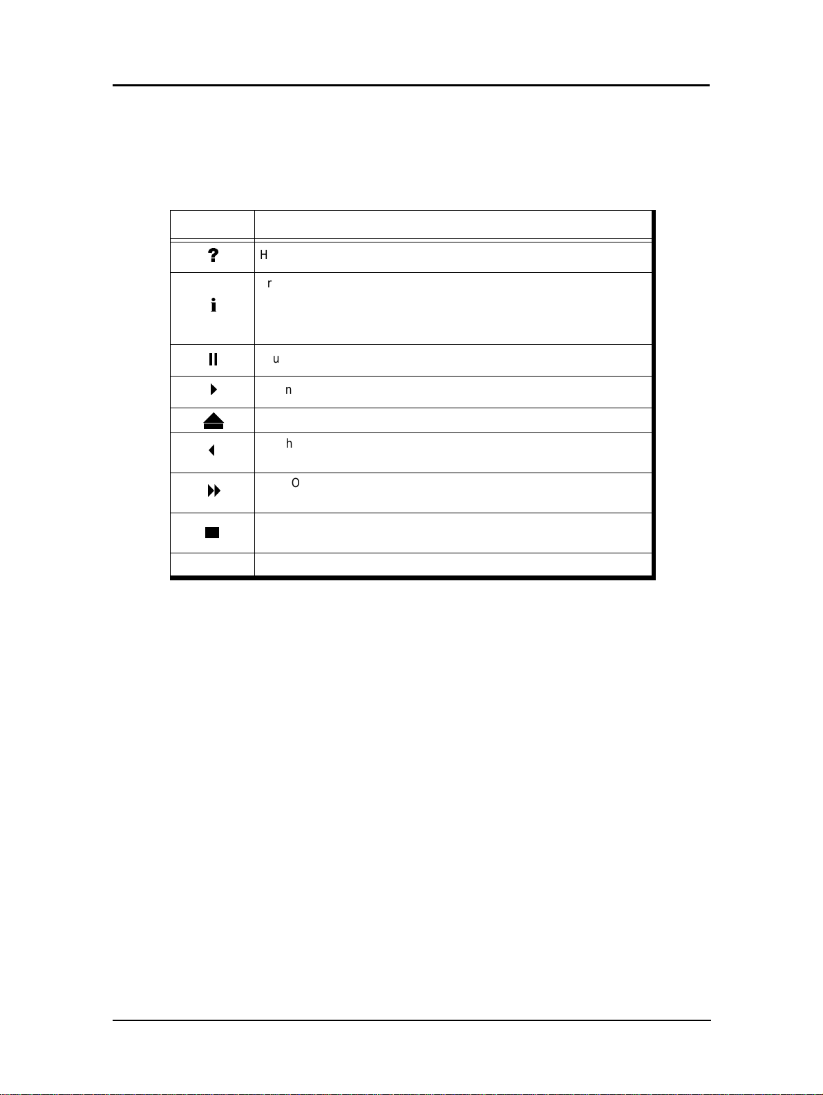
Using the Menu Screen s
The menus are accessed via the touch panel. Each OCP screen consists of icons that
you use to make selections. The icons that are used through the OCP screens are shown
below. Examples of the OCP screens are shown on the following pages.
Icon Function
"
L
;
4
3
8
Status Bar Displays the current screen name and/or any system messages.
Help. Touch to display Help on the current screen.
From the Main Menu, displays information about the printer and
consumables.
From relevant screens, displays an illustration of the paper trays or
finisher trays.
Touch to pause the printer.
When the printer is offline, touch to return to Ready status.
Touch to cancel the current selection and return to the Main Menu.
Touch to cancel the current selection and return to the previous screen
or menu.
More Options. Touch to display additional options for the current
selection.
Confirm or Done. Touch to confirm your selection and return to the
previous screen or menu.
Operator Control Panel 2-9
Page 28
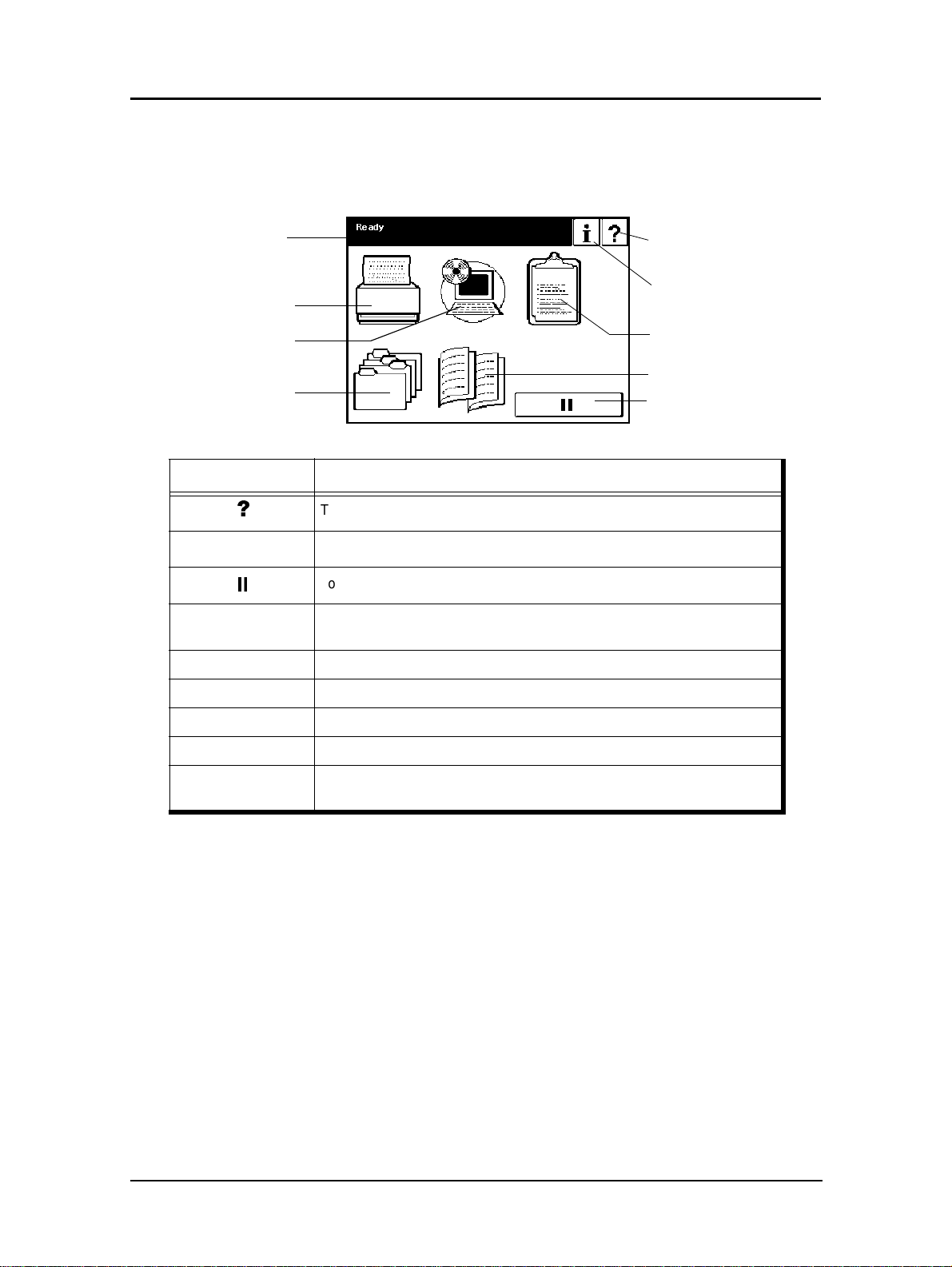
Main Menu
The Main Menu screen is shown below . A description of the elements that make up the
screen follows.
Status Bar
Ready
Printer Menu
Setup Menu
Jobs Menu
Icon Function
"
i
;
Status Bar
Printer Menu Touch to display the Printer Menu.
Setup Menu Touch to display the Setup Menu.
Touch to open Main Menu Help.
Touch to display information about the printer and consumables.
Touch to pause the printer.
Consists of one or two lines of text for displaying messages and
instructions.
Help
Current Screen
Information
Reports Menu
Finisher Menu
Pause/Offline
Reports Menu Touch to display the Reports Menu.
Jobs Menu Touch to display the Cancel Printing screen and view a list of all jobs.
Finisher Menu
Touch to display the Finisher Me nu. Available only when a Finisher is
installed.
2-10 Operator Control Panel
Page 29
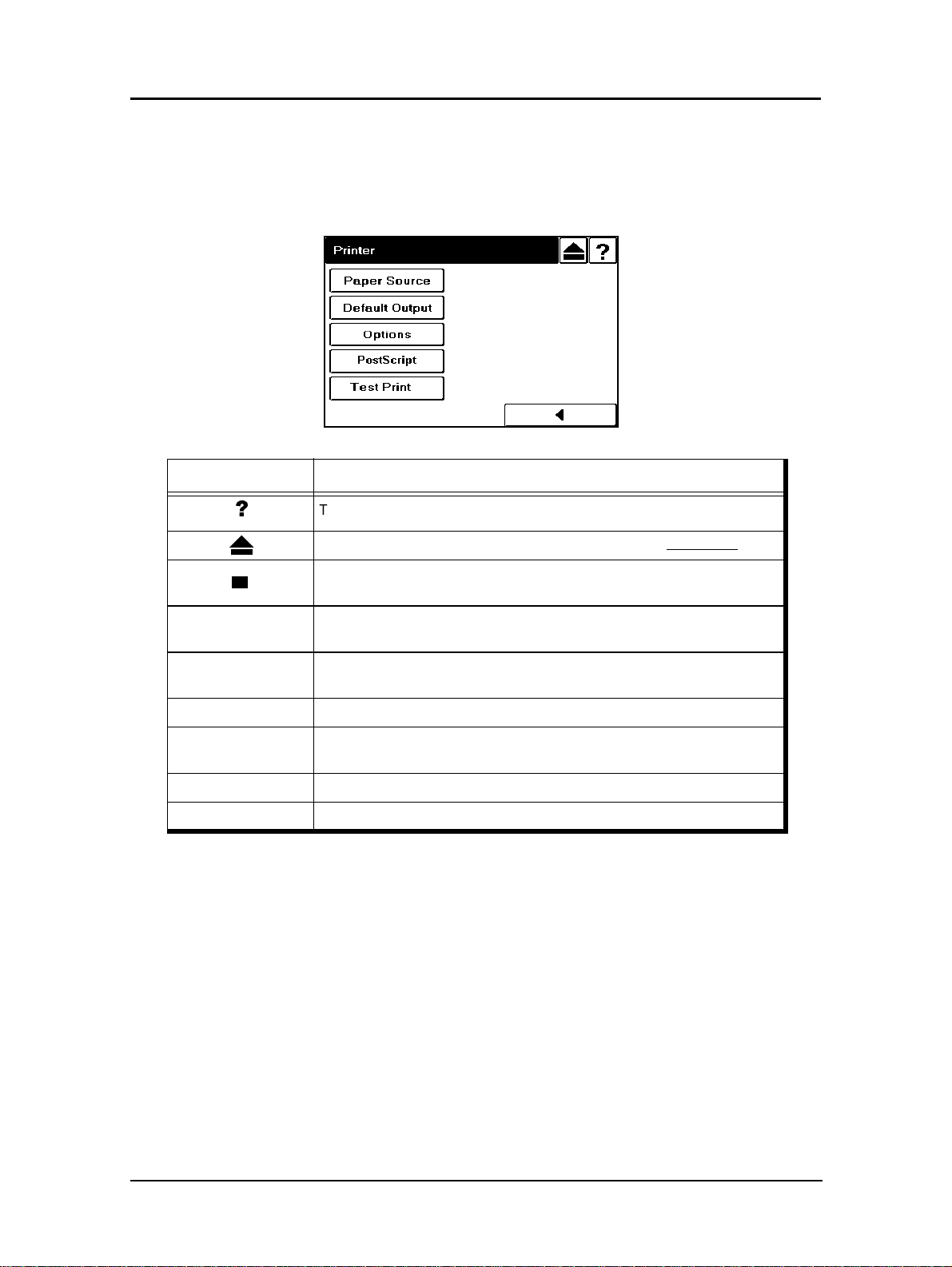
Printer Menu
When you select Printer from the Main Menu, this screen is displayed. Y ou use the
Printer Menu to gain access to the printing options described in the table below.
Icon Function
"
Status Bar
Paper Source
Default Output Touch to display paper output options.
Options
PostScript Touch to display the PostScript options.
Test Print Touch to display options for printing engine test patterns.
Touch to open Printer Menu Help.
Touch to cancel the current selection and return to the Main Menu.
Confirm or Done. Touch to confirm any selections you have made and
return to the main menu.
Consists of one or two lines of text for displaying messages and
instructions.
Touch to displ a y Paper S ourc e. You use this screen to gain a ccess to the
paper source options.
Touch to disp l ay the ava ilable o pti ons, including E xit-Jam R eco very, Wait
Timeout, and Duplex-Always mode.
Operator Control Panel 2-11
Page 30
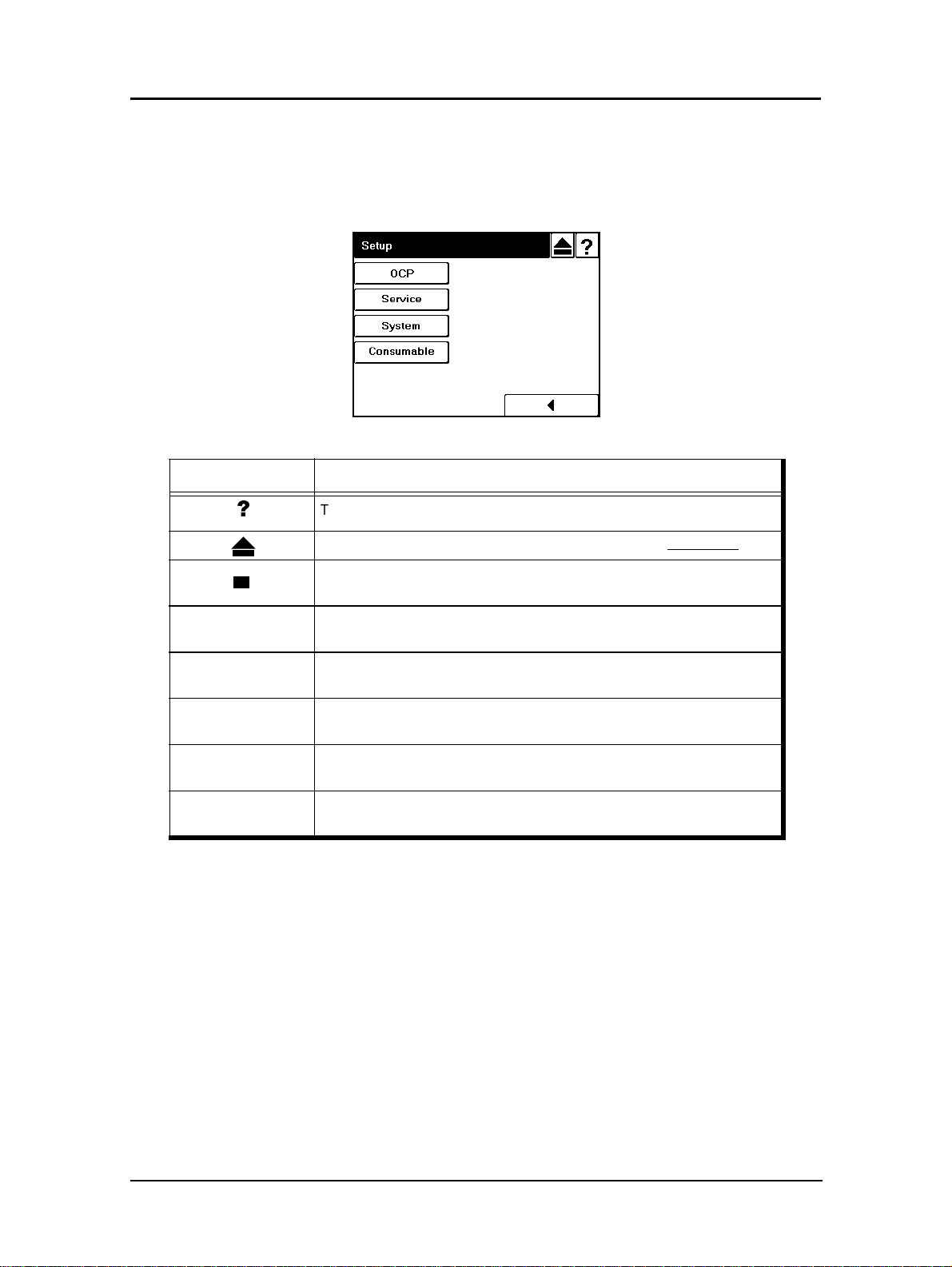
Setup Menu
When you select Setup from the Main Menu, this screen is displayed. Use it to gain
access to the Setup option screens that are described in the table below.
Icon Function
"
Status Bar
OCP
Service
System
Consumables
Touch to open Setup Help.
Touch to cancel the current selection and return to the Main Menu.
Confirm or Done. Touch this button to confirm any selections you have
made and return to the Main Menu.
Consists of one or two lines of text for displaying messages and
instructions.
Touch to display the OCP screen. You use this screen to adjust the
brightness and contrast values for the OCP display.
The Service option is password protected. Contact your
Service Technician for more information.
The System option is password protected. Contact your Network
Administrator if you need access to this option.
Touch to display the user consumable options, which include replacing
the developer mix, drum unit, and fuser web.
2-12 Operator Control Panel
Page 31

Reports Me nu
When you select Reports from the Main Menu, this screen is displayed. You use it to
print the reports described in the table below.
Icon Function
"
Status Bar
Status
Demo Touch to print a demo report and return to the Main Menu.
Summary Touch to print a summary report and return to the Main Menu.
Disk Directory Touch to print a disk directory report and return to the Main Menu.
Fonts
Touch to open Reports Help.
Touch to cancel the current selection and return to the Main Menu.
Confirm or Done. Touch this button to confirm any selections you have
made and return to the main menu.
Consists of one or two lines of text for displaying messages and
instructions.
Touch to print a status report and return to the Main Menu. The status
report shows the current configuration of the printer.
Touch to display the fonts summary options (PCL Fonts and PostScript
Fonts).
Operator Control Panel 2-13
Page 32

Finisher Menu for the Book let Fin isher (92 pp m only)
When you select the Finisher icon from the Main Menu, this screen is displayed. Yo u
use it to gain access to the Finisher options described below. Note that this screen is
only available when the Booklet Finisher is installed.
Icon Function
"
Inserter Touch to display the Inserter options.
Stapler Touch to display the staple positioning screen.
Folder Touch to display the folder positioning screen.
Touch to open Finisher Help.
Touch to cancel the current selection and return to the Main Menu.
Confirm or Done. Touch this button to confirm any selections you have
made and return to the main menu.
2-14 Operator Control Panel
Page 33

Finisher Menu for the Publ ishing Fi nisher
When you have the optional Publishi ng Finisher installed and you select t he Finisher
icon from the Main Menu, this screen is displayed. You use it to gain access to the
Publishi ng F inisher opt ions described below.
For detailed information on using the Publishing Finisher, refer to the Publishing
Finisher User’s Guide.
Inserter
Stapler
Trimmer
Folder
Icon Function
"
Touch to open Finisher Help.
Touch to cancel the current selection and return to the Main Menu.
Confirm or Done. Touch this button to confirm any selections you have
made and return to the Main Menu.
Touch to display options for the Publishing Finisher Inserter trays. You use
this screen to select the paper size, type, and weight for the Inserter trays.
Touch to display the Publishing Finisher Stapler screen. You use this
screen to modify the position of the staples in your booklets.
Touch to display the Publishing Finisher Trimmer screen. You use this
screen to specify the amount to be trimmed from the fore-edge of your
booklets.
Touch to display the Publishing Finisher Folder screen. You use this
screen to adjust the position of the fold in your booklets. Adjustments
may be necessary based on sheet quality, direction, and thickness.
Operator Control Panel 2-15
Page 34

Finisher Menu for the Container Stacker
When you have the optional Container Stacker installed and you select the Finisher
icon from the Main Menu, this screen is displayed. You use it to gain access to the
Container Stacker options.
For additional information on the Container Stacker, refer to the Container Stacker
User’s Guide.
Icon Function
"
Short Stacking
Decurler
Touch to open Finisher Help.
Touch to cancel the current selection and return to the Main Menu.
Confirm or Done. Touch this button to confirm any selections you have
made and return to the Main Menu.
Touch to enable or disable short stacking mode. Short stacking mode
lets you limit the amount of paper that can be delivered to the stackers.
Touch to display the Decurler screen, where the options for decurler are
AutoSelect, Enable, and Disable. Note that activating the decurler may
cause paper jams when printing with 28 lb bond or heavier paper.
2-16 Operator Control Panel
Page 35

Password s
Passwords provide security to restrict access to system parameters and certain printer
maintenance functions. Two types of passwords are available with your printer: a
system passwor d a nd a service password.
The system password is used by your System Administrator and provides access to the
system parameters. The service password is used by your Service Technician and
provides access to service and maintenance functions as well as the system parameters.
For additional information, contact your Syste m Administ rator.
Operator Control Panel 2-17
Page 36

2-18 Operator Control Panel
Page 37

What This Chapter Provides
This chapter contains information on the following topics.
n
Paper Weights
n
Unacceptable Paper
n
Storing Paper
n
Paper Sizes, Types, and Trays
n
Loading Pape r
n
Setting Custom Paper Size Values
n
Setting Tray Adjust Value s
Chapter 3
Paper Handling
Paper Handling 3-1
Page 38

Paper
T o obtain good print quality, u se the recommended paper and properly position it in the
correct trays. For the desired paper orientation, see the labels on the trays. Refer to
Appendix C for detailed information about paper specifications and printing on special
print media.
Paper Weights
The printer accepts the following paper weights in all paper trays, including the MBT
and HCF:
n
Bond paper: 16-53 lb (60-199 g/m2)
n
Index paper: 90-110 lb (163-199 g/m2)
Unacceptable Paper
Avoid using the following media as they cause paper jams and print quality problems.
n
Excessively thick or thin paper
n
Paper that has already been printed (preprinted letterhead is allowed)
n
Wr inkled, tor n, or bent paper
n
Moist or wet paper
n
Curled pap er
n
Paper with an electrostatic charge
n
Glued paper
n
Paper with special coating
n
Colored paper with surface treatment
n
Paper unable to withstand temperature of 302°F (150° C)
n
Thermal paper
n
Carbon paper
n
Paper with paper fasteners, ribbons, tape, etc., attached
n
Heavily textured paper
n
Label stock with exposed backing sheets
Storing Paper
Store the paper properly to avoid print quality problems and paper jams.
n
Store paper horizontally, in a flat, dry location to avoid wrinkling, bending,
curling, etc.
n
Store paper away from direct sunlight.
n
Store any unused paper in its origi nal packing.
3-2 Paper Handling
Page 39

Paper Size s, Paper Types, and Printer Inp u t Trays
The following tables show which paper sizes and types can be used with the printer’s
input trays. The paper size is shown in both millimeters and inches. The term SEF
indicates the paper is being fed into the printer short edge first and the term LEF
indicates the paper is being fed into the printer long edge first.
Paper Size
A5 (SEF) 149.0/5.83 210.0/8.26 2, 3 only
B5 (LEF) 257.0/10.13 182.0/7.17
A4 (SEF) 210.0/8.3 297.0/11.7
A4 (LEF) 297.0/11.7 210.0/8.3
B4 (SEF) 257.0/10.1 364.0/14.3
A3 (SEF) 297.0/11.7 420.0/16.5
Letter (LEF) 279.0/11.0 216.0/8.5
Letter (SEF) 216.0/8.5 279.0/11.0
Tabstock (Letter LEF) 374.0/11.0 279.0/9.0
Tabstock (A4 LEF) 297.0/11.7 225/8.85
Folio (SEF) 216.0/8.5 330.0/13.0
Legal (SEF) 216.0/8.5 356.0/14.0
Ledger (SEF) 279.0/11.0 432.0/17.0
Super B (SEF) 305.0/12.0 457.0/18.0
Statement (SEF) 216.0/8.5 140.0/5.5
Executive (LEF) 267.0/10.5 184.0/7.255
Custom
(0.1 mm/0.1 in. increments)
Leading Edge
mm/inch
140.0 to 305.0/
5.5 to 12.0
Side Edge
mm/inch
183.0 to 457.0/
7.2 to 18.0
Tray
1, 2, 3
áá
áá
ááá
áá
áá
ááá
áá
áá
á
áá
áá
áá
áá
2, 3 only
2, 3 only
á
*
HCF MBT
á
á
á
á
* Tray 1 can be adjusted; however, the physical settings are limited to standard paper sizes. Use
of custom size paper may result in skewing.
Paper Type Tray 1, 2, 3 HCF MBT
Label
Letterhead
Pre-printed
Pre-punched
Tab Stock
Transparencies
ááá
ááá
ááá
áá
á
á
Paper Handling 3-3
Page 40

Loading Paper
Load paper into the trays according to the instructions that follow . See “Loading
Special Media” on page 3-11 for directions on loading prepunched and preprinted
paper, as well as tab stock. Paper can be loaded while a print job is running, except into
the tray that is currently in use.
Loading Paper in Tray 1
WARNING!
Do not open Tray 1 if the Fuser Unit is pulled out. The printer may tip over
causing personal injury or damage to the printer.
1. Open the tray by pulling it by the handle.
2. Adjust the size guide to the proper size. The available sizes are marked on the
tray.
3-4 Paper Handling
Page 41

3. Adjust the sensor plate to the proper size. Size markers are located on the sensor
plate in the following order: triangle (special), B5, A5, LGR, LGL, L TR, B4, A3,
and A4.
If the paper size you need is not listed, set the sensor plate to triangle (the first
position). Then, in Step 6, you will select the paper size from the OCP display.
4. Place the paper into the tray.
NOTE:
The paper should be loaded no higher than the Max. level indicator. The
Max. level indicator is located inside the tray.
5. Close the tray.
6. If you set the sensor plate to triangle in Step 3, select the paper size from the OCP
by making the following selections:
Printer/Paper Sourc e / Pa pe r Size/tray number/paper size
7. Adjust the paper weight. The default paper weight is 20 lb. bond. If necessary,
change the paper weight by making the following selections:
Printer/Paper Source/
8. Select In de x, Bon d, or g/ m
8
/Paper Weight/tray number
2
, then use the keypad to input the weight and press <.
Paper Handling 3-5
Page 42

Loading Paper in Tray 2 or 3
1. Open the tray.
2. Adjust the size guide to the proper size. The available sizes are marked on the
bottom of the tray.
3. Adjust the sensor plate to the proper size. Size markers are located on the sensor
plate in the following order: triangle (special), B5, A5, LGR, LGL, L TR, B4, A3,
and A4.
If the paper size you need is not listed, set the sensor plate to triangle (the first
position). Then, in Step 6, you will select the paper size from the OCP display.
3-6 Paper Handling
Page 43

4. Place the paper into the tray.
NOTE:
The paper should be loaded no higher than the Max. level indicator. The
Max. level indicator is located inside the tray.
5. Close the tray.
6. If you set the sensor plate to triangle in Step 3, select the paper size from the OCP
by making the following selections:
Printer/Paper Sourc e / Pa pe r Size/tray number/paper size
7. Adjust the paper weight. The default paper weight is 20 lb. bond. If necessary,
change the paper weight by making the following selections:
Printer/Paper Source/
8. Select In de x, Bon d, or g/ m
8
/Paper Weight/tray number
2
, then use the keypad to input the weight and press <.
Paper Handling 3-7
Page 44

Loading Paper into the MBT
1. Open the MBT by pulling it by the handle.
2. Adjust the size guide to the proper size. The paper size positions are marked on
the bottom of the tray and on the top of the size guide.
3-8 Paper Handling
Page 45

3. Push down the paper tray.
4. Set the paper onto the tray.
Paper Handling 3-9
Page 46

Loading Paper into the HCF
WARNING!
The table inside the HCF automatically descends when you open the door
of the HCF. Do not allow anything to be c aught between the tabl e and the
bottom of the HCF.
1. Open the door of the HCF by pulling it by the handle. The table inside the HCF
automatically moves to its lowermost position and stops.
2. Set the paper into the HCF. (The HCF is set to handle Letter LEF or A4 LEF size
only. A service call is required to change from one size to the other.)
NOTE:
The paper should be loaded no higher than the Max. level indicator. The
Max. level indicator is located inside the HCF.
3. Close the door.
Refer to graphic
3-10 Paper Handling
Page 47

Loading Special Media
Pre-punche d Pa per
Load pre-punched paper as indicated in the following diagrams. Refer to Appendix C
for more information about using pre-punched paper.
Table 3-1. Simplex Printing (Single-sided)
Paper Size Orientation
Loading into
Tray 1 - 3 MBT or HCF
Letter/A4
Ledger/A3 Portrait
Ledger/A3 Landscape
Letter/A4 Portrait
Letter/A4 Landscape
Portrait and
Landscape
Ledger/A3
Portrait and
Landscape
Arrows indicate paper feed direction.
Paper Handling 3-11
Page 48

Table 3-2. Duplex Printing (Double-sided)
Paper Size Orientation
Portrait and
Letter/A4
Ledger/A3
Ledger/A3
Ledger/A3
Landscape
(Long Edge Bind)
Portrait
(Short Edge Bind )
Landscape
(Short Edge Bind )
Portrait and
Landscape
(Long Edge Bind)
Loading into
Tray 1 - 3 MBT or HCF
Letter/A4
Letter/A4
Portrait
(Short Edge Bind )
Landscape
(Short Edge Bind )
Arrows indicate paper feed direction.
3-12 Paper Handling
Page 49

Loadin g Pr e-printe d Pa p e r
Load pre-printed paper as indicated in the following table. Refer to Appendix C for
more details about using pre-printed paper.
Paper Type
Front/Back Side
Predetermined
Page Number
Predetermined
Note 1: The restriction of 9 inches only applies to printers with a powered Finisher or
Print
Mode
Simplex Front side down Front side up
Paper up to 9 in.(feed directi on ),
front side down
Duplex
Simplex First sheet on top, face down First sheet on top, face up
Duplex
Paper longer than 9 in. (feed
direction), front side up (See
Note 1.)
Paper up to 9 in. (feed directio n),
first sheet on top, face down
Paper longer than 9 in. (feed
direction), first sheet on top, face
up (See Note 1.)
Tray 1 - 3 MBT/HCF
Loading Into
Front side up
First sheet on top, face up
Container Stacker installed because the printer does not support face-up delivery of paper
longer than 9 in. to a powered Finisher or Container Stacker.
Paper Handling 3-13
Page 50

Loadin g Tab Stock
1. Load tab stock as shown in the illustration below.
NOTE:
Avoid bending the tabs or the corners of the tab dividers as this will
increase the likelihood of a jam occurring during the printing pr o cess. If a
jam does occur, refer to page 4-25 for instructions on jam recovery.
In the main paper trays, place the straight edge of the tab stock against the straight
right leading edge of the paper tray. T he tabs should be on the left, also known as
the trailing edge. In the MBT, place the straight edge into the machine. Tab stock
cannot be used in the HCF.
Top
Bottom
Load only complete tab sets. The first tab in the set should be on top of the stack
and the last tab on the bottom. Adjust the paper guides so that they hold the tab
stock securely in position in the tray.
NOTE:
You must set the sensor plate in the tray to the first position (denoted by a
triangle).
2. Select the paper size from the OCP by making the following selections. (If the tab
stock is not 9 in. by 11 in., select Custom Size.)
Printer/Paper Source/Paper Size/tray number/Le tte rTab or Custom Size
3. If you selected Custom Size in step 2, see “Setting the Custom Paper Size Values”
on page 3-15 for instructions on entering the custom paper size.
3-14 Paper Handling
Page 51

Setting the Custom Paper Size Values
If the paper size you have selected is a custom size you must set the paper size using
the OCP. First, follow the steps for loading paper into the desired tray, then perform
these steps.
1. On the Custom Paper Size screen, touch the value box for the leading edge (the
arrow in the illustration points to the leading edge). The Custom Paper Size Input
screen is displayed.
2. Using the number pad, enter the value for the leading edge of the paper.
3. Press the
entered is shown.
4. Touch the value box for the side edge. The display ret urns to Custo m Paper Size
Input.
5. Using the number pad, enter the value for the side edge of the paper.
6. Press the
you have entered are displayed.
7. Press the
<
key. The display r etur ns to Cu stom Pap e r S ize an d th e va lue you h ave
<
key. The display returns to Custom Paper Size and now both values
<
key. Your custom paper size settings are now saved.
Setting the Tray Adjust Values
The tray adjust feature is used when it is necessary to shift the image on the printed
page. You can shift the image
you can set different tray adjust values for the front side and back side of the paper.
1. To display the Tray Adjust screen, make the following selections from the OCP:
Printer/Paper Source/
2. On the Tray Adjust screen, touch the left-most value box. The Tray Adjust Input
screen is displayed.
± 0.25 in. (± 6.3 mm). When printing in duplex mode,
8
/Tray Adjust/tray number
3. Using the number pad, enter the value for the feed direction of the paper. For
example, entering + 0.25 moves the image 0.25 in. to the right on the printed page.
4. Press the
have entered is shown.
5. Touch the bottom-most value box. The display returns to Tray Adjust Input.
6. Using the number pad, enter the value for the scan direction of the paper. For
example, entering + 0. 25 moves the image 0.25 in. to the top of the printed page.
7. Press the
values you have entered are displayed.
8. Press the
<
key. The display returns to the Tray Adjust screen and the value you
<
key. The display returns to the Tray Adjust screen and now both
<
key. Your tray adjust settings are now saved.
Paper Handling 3-15
Page 52

3-16 Paper Handling
Page 53

What This Chapter Provides
This chapter contains the following information:
n
Replacing Consumables
n
Clearing Paper Jams
n
Cleaning the Printer
n
Handling and Storing Consumables
Chapter 4
Care and Maintenance
Care and Maintenance 4-1
Page 54

Replacing Consumab le s
When a consumable needs to be replaced, the printer stops printing and displays an
error message indicating which consumable should be replaced. The following table
shows the life expectancy of each consumable.
Consumable Average Life Expectancy
Toner 36,000 images (5% coverage1)
Developer Mix 480,000 images (600,000 drum rotations)
Drum Unit 400,000 images (500,000 drum rotations)
Fuser 1,600,000 images
Fuser Cleaning Web 320,000 images
Toner Collector Bottle Every other refill of the toner
NOTE:
“Image” means paper size of Letter/A4 LEF. Other page sizes will have
“images” based on Leng t h of Form/8.5”.
External factors can affect the average yield of consumables. Some of these factors are:
n
Humidity
n
Temperature
n
Type of paper
n
Run length of jobs
n
Adequate ventilation around equipment
n
Image coverage on page
n
Print Utilization - if less than 80%, projected consumable life may become shorter
n
Print density
1
Coverage is calculated per printed sheet and is defined as the ratio of area with toner to the total area of
the sheet. Toner usage is based on 5% coverage when the toner density level is set to the default value.
The following items affect toner coverage: the printed image content, the paper used, and the condition
and calibration of the printer. Actual toner usage may vary due to these factors.
4-2 Care and Maintenance
Page 55

Adding Toner
1. Open the Toner Supply Cover.
2. Make sure that the mouth of the toner bottle is closed. Shake the toner bottle up
and down about six times, then turn the toner bottle upside down and shake it
again.
Toner Supply Cover
Toner Hopper Unit
5 - 6 times 5 - 6 times
CAUTION!
Toner is not harmful to the human body, but if some toner has come in
contact with your skin or clothes, you shoul d wash it immediately with
cold water.
Care and Maintenance 4-3
Page 56

3. Peel the toner seal film.
NOTE:
Before peeling the toner seal film, make sure that the projection of the
toner bottle cap is located at the click point. If it is not, turn the bottle cap
counterclockwise to move the projection to the click point as shown in the
figure below, and then peel the seal film.
4. Install the toner bottle into the T oner Hopper Unit so that the triangle marks on the
bottle mouth and the Toner Hopper Unit line up. Turn the bottle in a half circle
until the triangle mark on the bottle comes to fit the circle mark on the Toner
Hopper Unit.
Toner Bottle
Circle Mark
4-4 Care and Maintenance
Page 57

5. Hold the top of the bottle and tap the side to transfer the toner into the Toner
Hopper Unit.
6. When the toner bottle is empty, turn it back in a half circle and take it out.
Empty Toner Bottle
180°
7. Close the Toner Supply Cover and discard the empty toner bottle.
Care and Maintenance 4-5
Page 58

Replacing the T oner Collector Bottle
When the OCP displays the message Toner Bottle Full, replace the Toner
Collector Bottle with a new empty bottle.
1. Open the T one r Collector Bottle Cover and the Inner Cover. (The Toner Cover
Door is located at the right side of the printer next to the MBT. )
2. Remove the old T oner Collector Bottle.
Inner Cover
Install Remove
Toner Collector
Bottle Cover
Empty Toner Bottle
3. Remove the cap from the side of the Toner Collection Bottle and place it on top of
the bottle to seal it.
Cap
4. Install a new T one r Collector Bot tle. (See illustration for Step 2.)
5. Close the Inner Cover and the Toner Collector Bottle Cover.
4-6 Care and Maintenance
Page 59

6. Dispose of the full toner bottle properly.
WARNING!
Waste materials should be disposed of or incinerated under conditions
which meet all federal, state and local environmental regulations. Since
regulations may vary from one r egion to another, check with the agency
that govern s waste dispos al in your area for proper procedures.
Replacing the Developer Mix
Replacing t he develope r mix is a two-phase process. First you exhaust the Developer
Mix, and then you supp ly it.
Exhausting the Developer Mix
1. Take the empty developer bottle out of the box.
2. Open the Front Cover of the printer.
3. Attach the empty developer bottle to the Developer Unit Duct so that the slit of
the bottle fits the projection of the duct.
Projection
Slit
Care and Maintenance 4-7
Page 60

4. Lock the empty developer bottle by turning the developer bottle cap about 160
degrees in the direction shown below.
160°
CAUTION!
Hold the developer bottle when you turn the cap so that the bottle is not
turned together with the cap.
5. To start the exhaust process, make the following selections from the OCP:
Setup / Consumable / Developer Mix / Exhaust
The exhaust process takes approximately 2 minutes.
6. Remove the developer bottle by turning the bottle cap back about 160 degrees in
the direction shown below .
4-8 Care and Maintenance
Page 61

Supplying the Developer Mix
Be sure to use only the developer mix that is specified for the printer . Usin g developer
that is not specified for the printer may degrade print quality or cause damage to the
printer. Refer to the table below to determine the correct developer mix for your printer.
Printer Model
DDP 70 399071-900 White
Developer Mix
Part Number Label Color
DDP 70k, DDP70e,
and DDP92
* Use developer mix Type-K (with a green
label) when the seal shown at right is
pasted on the duct of the developer unit.
337600-003 Green*
1. Take the new developer bottle out of the box and shake it.
2. Remove the duct cap from the developer duct.
3. Place the new developer bottle onto the developer unit duct.
Cap
Care and Maintenance 4-9
Page 62

4. Lock the bottle in place by turning the developer bottle cap about 160 degrees in
the direction shown below.
160°
CAUTION!
Hold the developer bottle when you turn the cap so that the bottle is not
turned together with the cap.
5. To start the replacement process, make the following selections from the OCP:
Setup / Consumable / Developer Mix / Supply
The replacement process takes approximately 2 minutes. (Maximum replacement
time is 4
½ minutes.)
6. Turn the cap back about 160 degrees in the direction shown and remove the
developer bottle.
160
°
4-10 Care and Maintenance
Page 63

7. Place the duct cap back on the developer duct.
8. Clean any spilled developer from the printer.
9. Close the Front Cover..
NOTE:
Save the empty developer bottle for use during the next developer exhaust
process.
Care and Maintenance 4-11
Page 64

Replacing the Drum Unit
T o remove the Drum Unit:
1. Open the Front Cover of the printer.
2. Turn the handle clockwise to release the Drum Unit.
TH
Handle
3. Turn the Drum Center Lock until the tab on the side of the lock appears. Push the
tab to release the Lock. Pull the drum center lock out of the center shaft.
Drum Center Lock
Tab
4-12 Care and Maintenance
Page 65

4. Using the grip of the front side of the drum unit, pull it out until the stopper
behind the unit catches, then hold the handle and lift the drum unit to remove it.
Drum Unit
Handle
Drum Unit
Front Guide
Care and Maintenance 4-13
Page 66

To install the new Drum Unit:
1. Align the groove on both sides of the Drum Unit to the Drum Unit Front Guides
that are located on the front side of the Console Frame. Push the front grip of the
Drum Unit until the Drum Unit is set in the proper position.
Drum Unit Front Guide
Center Shaft
Groove
Front Grip
2. Replace the Drum Center Lock on the Center Shaft. Push the lock until it latches.
Make sure the lock is latched by pulling. It should not come back out.
3. Turn the handle counterclockwise to close the TH unit.
4. Close the Front Cover of the printer.
5. T o clear the usage counter for the Drum Unit, make the following selections from
the OCP:
Setup / Consumable / Drum Unit /
4-14 Care and Maintenance
Page 67

Replacing the Fuser Cleaning Web
To remove the Fuser Unit:
1. Open the Front Cover of the printer.
WARNING!
The Fuser Unit is very hot. Do not touch any parts of the Fuser Unit
except those parts which are used to replace the Fuser Cleaning Web.
Do Not open the Fuser Unit and Tray 1 at the same time. The printer may
tip over causing personal injury or damage to the printer.
2. Hold up the Fuser Latch and pull out the Fuser Unit.
Fuser Latch
Fuser Unit
Care and Maintenance 4-15
Page 68

3. Open the W eb Holder Plate as shown below.
Web Holder Plate
4. Pull the handle up and use it to lift the Fuser Cleaning W eb out of the Fuser Unit.
Handle
Fuser
Cleaning Web
4-16 Care and Maintenance
Fuser Unit
Page 69

To install the new Fuser Cleaning Web:
1. Slide the Fuser Cleaning Web into the slots of the Fuser Unit and lock it into place
by pushing down the handle.
Handle
Slot
2. Close the Web Holder Plate and push the Fuser Unit back in.
3. Close the Front Cover.
4. To clear the usage counter for the Fuser Web, make the following selections from
the OCP:
Setup / Consumable / Fuser Web /
Replacing Staples
For staple replacement instructions refer to your option-specific finisher user’s guide.
Slot
Care and Maintenance 4-17
Page 70

Clearing Paper Jams
This section addresses printer paper jams only. If a paper jam occurs in the finisher,
refer to your option-specific finisher user’s guide, or the Quick Reference Guide.
Vertical Path Cover
Follow the steps below to clear paper from the Vertical Path Cover.
NOTE:
The Vertical Path Cover is also referred to as the “Input Station Cover”
(IS cover).
1. Open the Vertical Path Cover and remove the jammed paper. Paper along the
paper path is automatically ejected from the Vertical Path Cover.
2. Close the Vertical Path Cover.
3. Touch
4-18 Care and Maintenance
4
on the OCP to clear any error messages.
Page 71

Switch Back Area
Follow the steps below to clear paper from the Switch Back Area.
1. Open the Finisher Cover and the Tab.
Finisher
Cover
2. Open the Switch Back Cover.
NOTE:
The Switch Back Cover is located on the left side of the printer, but is
accessed from inside of the Finisher.
Tab
Switch Back Cover
Care and Maintenance 4-19
Page 72

3. Turn the Fuser Unit Handle to the RELEASE position and rotate the blue knob in
the direction shown below to remove the jammed paper.
NOTE:
The jammed paper may come out of the slit below the cover.
Fuser Unit
Handle
Knob
Slit
4. Close the Switch Back Cover. Then close the Tab and the Advanced Finisher
Cover.
5. Touch
4
on the OCP to clear any error messages.
4-20 Care and Maintenance
Page 73

Paper Feed Block Area
Follow the steps below to clear paper from the Paper Feed Block area.
1. Open the Front Cover.
2. Turn the TH handle and Fuser handle to the RELEASE position.
Fuser Handle
TH Handle
Care and Maintenance 4-21
Page 74

3. Rotate the blue knobs as shown below to remove any jammed paper.
Knobs
Paper
Guide Tabs
4. Turn the TH handle to the LOCK position.
5. In duplex printing, remove any jammed paper from the Paper Guide Tab. While
holding the Paper Guide T ab up, rotate each blue knob as shown below to remove
any jammed paper.
6. Turn the TH Handle and the Fuser handle to the LOCK position.
7. Close the Front Cover.
8. Touch
4-22 Care and Maintenance
4
on the OCP to clear any error messages.
TH Handle
Paper Guide Tab
Page 75

Trays 1, 2, and 3
Follow the steps below to clear paper from Trays 1, 2, and 3.
Tray 1
WARNING!
Do not open Tray 1 if the Fuser Unit is pulled out. T he printer may tip over
causing personal injury or damage to the printer.
1. Open the tray and remove the jammed paper.
Tray 2 or 3
2. Close the tray.
3. Touch
1. Open the tray and remove the jammed paper.
2. Close the tray.
3. Touch
4
on the OCP to clear any error messages.
4
on the OCP to clear any error messages.
Care and Maintenance 4-23
Page 76

Multi-bypass Tray
Follow the steps below to clear paper from the MBT.
1. Remove the jammed paper by pulling it out in the direction shown below.
2. Touch
4
on the OCP to clear any error messages.
High Capacity Feeder
Follow the steps below to clear paper from the optional HCF.
WARNING!
The table inside the HCF automatically descends when you open the door
of the HCF. Do not allow anything to be c aught between the tabl e and the
bottom of the HCF.
1. Open the door of the HCF and remove any jammed paper.
4-24 Care and Maintenance
Page 77

2. T ake out the Top Cover and remove any jammed paper.
3. Return the Top Cover to its original position and close the door of the HCF.
4. Touch
4
on the OCP to clear any error messages.
Tab Stock Jam Recovery
If a jam occurs when the tab stock is in the paper path, follow the steps below to clear
the printer and resume your print job. If there is no tab stock in the paper path, proceed
as you woul d for any paper jam.
1. Clear the jammed paper and tab stock from the paper path.
2. Determine which tab in the set was affected by the jam.
3. Open the paper tray that contains the tab stock. Remove tab stock from the stack
until the tab position that jammed is on top. Close the paper tray.
4. Return the printer to the on-line position and your print job will resume
automatically.
Care and Maintenance 4-25
Page 78

Cleaning the Printer
In order to maintain print quality, thoroughly clean the printer following the
instructions below . When cleaning the printer, pay particular attention to the notes and
cautions for safe maintenance.
CAUTION!
Power OFF the printer prior to cleaning.
Do not use solvent on the printer. Using solvent may dissolve the plastic
and paint of the printer.
Do not use cleaning solutions to clean inside and around the printer. Use
only a water-moistened cloth.
NOTE:
If the toner gets on your clothes, wipe it off with a dry cloth first and wash
the clothes in COLD water. Be careful not to use hot water as it permits the
toner to permeate into the fabric. Although the toner is nontoxic, avoid
breathing toner particles.
Cleaning the Printer Covers
1. Wipe with a water-moistened, lint-free, soft cloth.
2. Dry with a clean, lint-free soft cloth.
4-26 Care and Maintenance
Page 79

Cleaning the Inside of the Printer
1. Open the Front Cover.
2. Using a dry, lint-free cloth, clean inside the Front Cover by wipi ng any visible
toner away.
3. Close the Front Cover.
Cleaning Trays 1, 2 and 3, the MBT, and HCF
1. Open the tray and remove the paper.
2. Clean inside the tray, especially the corners, by wiping any visible toner away
with a dry lint-free cloth.
3. Load the paper back into the tray and close the tray.
Care and Maintenance 4-27
Page 80

Cleaning the Toner Bottle Joint
1. Open the Toner Supply Cover.
2. Clean insi de the Toner Supply Co ver by w ip ing an y v isib l e to ner aw ay wi th a dr y,
lint-free cloth.
3. Close the Toner Supply Cover.
Cleaning the Conveyance Belt Area
1. Open the Front Cover.
2. Turn the TH Handle to the RELEASE position.
3. Remove the Drum Unit. Refer to page 4-12 for instructions.
Toner Supply Cover
Toner Hopper Unit
4. Clean the Paper Guide, TR Guide, and the Lower Stay (C) by wiping any visible
dust away with a dry lint-free cloth.
Lower Stay (C)
TH Handle
Paper Guide
TR Guide
5. Replace the Drum Unit.
6. Turn the TH Handle to the LOCK position.
7. Close the Front Cover.
4-28 Care and Maintenance
Page 81

Cleaning the Toner Collector Bottle Area
1. Open the T one r Collector Bottle Cover and the Inner Cover.
2. Remove the Toner Collector Bottle.
3. Clean the Toner Collector Bottle Cover, Toner Collector Bottle Box, the surface
of the Bottle Shutter , and the Inner Co ver by wiping any visible toner away with a
dry, lint-free cloth.
Bottle Shutter
Toner Collector
Bottle Box
Inner Cover
4. Replace the Toner Collector Bottle.
Toner Collector
Bottle Cover
Toner Bottle
5. Close the Inner Cover and the Toner Collector Bottle Cover.
Care and Maintenance 4-29
Page 82

Handling and Storing Supplies and Con sum a bles
Paper
Proper handling and storing of paper are important to optimize the performance of the
printer. For best results, follow the instructions below.
When Loading
n
Be careful not to damage, crease, or fold paper when handling.
n
Eliminate any damaged paper before loading paper into the tray.
n
Do not load different types of paper into the same tray.
n
Remove any paper previously loaded in the tray when loading new paper. Do not
put new paper on the paper formerly loaded in the tray.
When Storing
n
Wrap the remaining paper to keep the proper moisture content.
n
Store the wrapped paper in an air-conditioned room. There should not be a
significant temperature difference between a paper storage environment and a
printer operating environment. It may cause paper jams.
When Paper Jams Frequently Occur
n
Replace the paper. Even if paper brands are same, characteristics may be slightly
different due to different environmental storage conditions.
n
Turn over the paper in the tray. This should not be applied when using paper
whose front side or back side is prearranged such as letterhead forms.
4-30 Care and Maintenance
Page 83

Toner and Developer
Proper handling and storage of the toner bottle and developer bottle are important to
optimize printer performance. For best results, follow the instructions below.
When Purchasing
n
Use only toner and developer which are specified for the printer . Print quality ma y
be degraded and troubles may occ ur if using t oner and deve loper that does not
meet the specification.
n
Store the toner bottle and developer bottle in a well air-conditioned place. If the
temperature is over 104°F (40°C), the toner and developer may solidify. The
recommended storing temperature is 14°F - 104°F (-10°C~40°C). The
recommended relative humidity is 5% to 80%. Do not store for longer than 3
years after the date of manufacture.
n
Do not expose developer to the air. If exposed, developer may rust and degrade
printing quality.
Care and Maintenance 4-31
Page 84

4-32 Care and Maintenance
Page 85

What This Chapter Provides
This contains the following information.
n
Guidelines Flowchart
n
Basic Troubleshooting Tips
n
General Printing Problems
n
Print Quality Problems
n
Duplex Printing Problems
n
OCP Display Messages
NOTE:
The following sections provide tro ubleshooting guidelines. If you are still
unable to resolve a problem, contact your authorized service center.
Chapter 5
Troubleshooting
Troubleshooting 5-1
Page 86

Guidelines Flowchart
Determine the type of problem.
The printer cannot
be powered on.
Check if the main
power distributor
switch is on.
Check if the
printer’s power
switch is on.
The printer cannot
be connected to
the host system.
Check the device
address definition
at the host
system. Correct if
incorrect.
Check the cable
connections to th e
printer.
Problem with print
quality.
Check paper,
toner, or
developer for its
quality, storing,
and handling
conditions.
Eliminate any
possible causes.
(See Chapter 3.)
Check if the
internal parts of
the printer are
contaminated.
Clean if
contaminated.
(See Chapter 4.)
Cannot perform
print jobs because
of a printer error.
Check the OCP
error message
and take the
appropriate
corrective action.
Contact service personnel if the trouble is not corrected with these guidelines.
5-2 Troubleshooting
Page 87

Basic Troubleshooting Tips
The following are some common situations that can cause a variety of problems. Before
you look for a specific problem use the tips in this list.
n
Check the power and all cables to the printer.
n
Check the printer OCP for information.
n
If possible, print the Status Page from the Reports menu and verify that the
settings match your configuration.
n
Check the current status of the printer.
r
The current status appears on the OCP.
r
If used with a MicroPress Server, check the Status field in the DDP-MP main
window.
If the printer is processing your job, the status message reflects this.
If your print job does not appear in the status message, another user’s job may
be print ing be fore yours or the p rinte r may already hav e fini shed pr int ing you r
job.
If your job is waiting to print, it appears in the list for the print queue.
Troubleshooting 5-3
Page 88

General Printing Problems
If this happens Try this
Paper handling problems
(jams)
Printer does not respond to
a Print command
Message requests a paper
size that you do not have
Status Page does not print
Print settings for your job
output do not match the
settings you gave
• Check pick rollers and clean area of problem paper source.
• Straighten paper stack of problem paper source.
• Try printing a Status Page from the Reports menu.
If you are able to print the Status Page but still cannot print a file from
your computer, contact your system administrator or your authorized
service/support center.
• Verify that you printed to the correct queue.
• If used with a MicroPress Server, check the DDP-MP terminal to verify
your job is in the queue and should be printing.
• If you are still unable to print, contact your system administrator.
1. Cancel the job .
2. Change the page size in the Print option of your application.
3. Resubmit the job.
• If the OCP shows a diagnostic or error message, take the appropriate
corrective action.
• If the OCP is completely blank, shut down and restart the printer. When
the printer reaches Ready status, try printing a Status Page from the
Reports menu. If the Status Page still fails to print, contact your
authorized service/support center.
• Verify that you did not override the setting for job in another place.
Print Quality Problems
If this happens Try this
Pages have toner streaks Cean the printer as described in Chapter 4.
Duplex Printing Problems
If this happens Try this
Duplex pages print upside
down
Change the Duplex print option that specifies how the second image is
placed relative to the first image.
5-4 Troubleshooting
Page 89

OCP Display Messages
The OCP displays the printer status with 1- to 2-line messages. There are three types of
messages: status, warning, and error messages. The following table lists the messages
in alphabetical order. Each message is explained and a corrective action is given when
applicable.
For information on messages not explained here, please refer to your option-specific
user’s guide .
Message Description Corrective Action
Booklet Stacker Full
Remove Booklets
Booklet Stacker Full
Remove Paper E027
Call for Service
Exxx or other text
Cle ari ng Err or Status message.
Container x Top Cover Open
Close Cov er
Container x V Path Cover Open
Close Cov er
Creating Software Log
Deleting Jobs
Developer Bottle Not Set
Set Developer Bottle E01E
Developer Charge
E0A1
Developer Discharge
E0A2
Developer Error
Retry Exhausting E048
Developer Error
Retry Operation E047
Developer Mix End of Life
Replace Developer E012
Drum Unit End of Life
Replace Drum Unit E016
Drum Wrap Sensor Error
Clean Wrap Sensor E018
Drum Wrap
Remove Paper E118
Drum Wrap
Remove Paper E119
Duplex-Always Duplex-Always mode is enabled.
Self-explanatory. Remove booklets.
Self-explanatory. Remove booklets.
Any “Call for Service ” mes sag e requires
a service call for problem resolution.
Line 2 is the error code.
The top cover of the co ntaine r is o pen.
x is the container number.
The v path cover of the container is
open. x is the container number.
Status message. The printe r is
creating the requested software log.
Status message. The selected jobs are
being deleted from the print queue.
The developer bottle is not seated
properly.
Replacement of the developer is
running.
Replacement of the developer is
running.
An error occurred when operating the
developer.
An error occurred when replacing the
developer mix.
The developer mixture needs to be
exchanged.
The photoconductive drum needs to
be replaced.
The drum wrap sensor level is
abnormal.
Simplex paper is wrapped around the
drum.
Duplex paper is wrapped around the
drum.
Contact your authorized Service
Technician and provide the error code
displayed on the OCP.
Wait for the print er to return to a Ready
state.
Close the cover.
Close the cover.
Wait for the print er to return to a Ready
state.
Wait for the print er to return to a Ready
state.
Reseat the bottle.
Wait for the print er to return to a Ready
state.
Wait for the print er to return to a Ready
state.
Retry . If the error occurs again, contact
an authorized Service Technician.
Retry . If the error occurs again, contact
an authorized Service Technician.
Replace developer. Printing will resume
when the de ve lo pe r i s re pl ac ed .
Contact your authorized Service
Technician.
Contact your authorized Service
Technician.
Remove the jammed paper.
Remove the jammed paper.
Contact your System Administrator for
additional information.
Troubleshooting 5-5
Page 90

Message Description Corrective Action
Elevator Tray Paper Full
Remove Paper E009
Elevator Tray Paper Full
Remove Paper E00A
Enter new password
Enter new password again
Enter service password
Enter system password
Entrance Paper Guide Open
Close Guide
Finisher Front Cover Open
Close Cover E03F
Front Cover Open
Close Cover E043
Fuser Unit End of Life
Replac e Fuser Unit E015
Fuser Web End of Life
Replac e Fuser We b E014
HCF Open
Close Tray E023
HCF Top Cover Open
Close Cover E046
Heater Off Mode Status message None
Input Keycode
Input Station Cover Open
Close Cover E044
Insufficient Disk Space
One Copy Job
Invalid Booklet
Clear Paper Path
Invalid Booklet
Cancel Job
Invalid Combination #1
Cancel Job
The output tray of the Advanced
Finisher is full.
Paper did not stack properly in the
output tray of the Advanced Finisher.
Passwords are for use by System
Administrators and Service
Technicians only.
Passwords are for use by System
Administrators and Service
Technicians only.
You must provide the service
password to gain access to the
selected menu item.
You must supply the system password
to gain access to the selected menu
item.
The Entrance Paper Guide is located
behind Front Cover R o f th e Publish ing
Finisher.
The front cover of the Advanced
Finisher is open.
Self-explanatory. Close the cover.
The fuser unit needs to be replaced.
The fuser cleaning web needs to be
replaced.
The door of the high capa city feede r is
open.
Self-explanatory. Close the cover.
A valid keycode is required to activate
this feature.
The IS cover is also referred to as the
vertical path cover.
There is not enough space for the
requested operation. Only one copy is
printed.
The Publishing Finisher cannot
perform the operation.
The Publishing Finisher cannot
perform the operation.
Incorrect stacker choice requested.
(Cannot deliver to Upper Tray from
Inserter.)
Remove paper from the elevator tray.
Remove paper from the elevator tray.
Contact your System Administrator for
additional information.
Contact your System Administrator for
additional information.
Contact your System Administrator if
you need access to menu items that
are password protected.
Contact your System Administrator if
you need access to menu items that
are password protected.
Close the guide com pletely, then close
the cover.
Close the cover.
Contact your authorized Service
Technician.
Contact your authorized Service
Technician.
Close the door.
Contact your System Administrator or
authorized Service Technician.
Close the cover.
Increase disk space or send job
multiple times.
Remove the remaining paper.
Cancel the job.
Cancel the job.
5-6 Troubleshooting
Page 91

Message Description Corrective Action
Invalid Combination #2
Cancel Job
Invalid Folder #xx
Clear Paper Path
Invalid Folder #xx
Cancel Job
Invalid Password
Invalid T ime Server Add re ss
Invalid Value Incorrect value entered. Re-enter value.
LED Eraser Not Set
Set Erase Lamp E080
Lifting Tray Name
Loading Fail Network Status message.
Loading Network Status message.
Low on Front Staples Status message. Have replacement staples available.
Low on Rear Staples Status message. Have replacement staples available.
Low Toner - Recovery
MBT
Load xx E090
Network Load Failed Network connection error. Check the Ethernet cable of the NIC.
Open Stacker Full The output tray is full. Remove the paper from the tray.
Out of Front Staples
Load Staples
Out of PF Front Staples
Load Staples
Out of PF Rear Staples
Load Staples
Out of Rear Staples
Load Staples
Paper in Connecting Unit
Remove Paper E073
Paper in Duplex Path
Remove Paper E05C
Paper in Fin Holding Path
Remove Paper
Paper in Fin Sheet Path
Remove Paper
Paper in Finisher
Remove Paper E064
Incorrect stacker choice requested:
(Cannot deliver to Container Stacker
from Inserter .)
The Booklet Finisher cannot perform
the operation.
The Booklet Finisher cannot perform
the operation.
A valid password is requi re d to acce ss
this area of the OCP.
Incorrect value in time server IP
address field.
The LED eraser is not set.
The specified tray is moving into the
feed position.
In process of supplying the toner.
E09A
The wrong paper size is loaded in the
multi-bypass tray.
The front stapler unit of the Advanced
Finisher is out of staples.
The front stapler unit of the Publishing
Finisher is out of staples.
The rear stapler unit of the Publishing
Finisher is out of staples.
The rear stapler unit of the Advanced
Finisher is out of staples.
Paper jam in connecting unit of the
Publishing Finisher.
Paper jam on return path 1. Remove the jammed paper.
Paper jam in holding path. Remove the jammed paper.
Paper jam in sheet path. Remove the jammed paper.
Paper jam in entrance path of the
Advanced Finisher.
Cancel the job.
Remove the remaining paper and
cancel the job.
Cancel the job.
Retry password. If incorrect, contact
your System Administrator.
Check the time server IP address via
the Web Utilities.
Contact your authorized Service
Technician.
Status message. Wait for the printer to
return to a Ready state.
Wait for the print er to return to a Ready
state.
Wait for the print er to return to a Ready
state.
Wait for the print er to return to a Ready
state.
Load the MBT with the requested
paper size.
Replace the front staple cartridge.
Replace the front staple cartridge.
Replace the rear staple cartridge.
Replace the rear staple cartridge.
Remove the jammed paper.
Remove the jammed paper.
Troubleshooting 5-7
Page 92

Message Description Corrective Action
Paper in Finisher
Remove Paper E065
Paper in Finisher
Remove Paper E066
Paper in Finisher
Remove Paper E067
Paper in Finisher
Remove Paper E068
Paper in Fuser
Remove Paper E070
Paper in Input Station
Remove Paper E050
Paper in Input Station
Remove Paper E051
Paper in Input Station
Remove Paper E052
Paper in Input Station
Remove Paper E072
Paper in Input Station
Remove Paper E056
Paper in Open Stacker
Paper in Paper Exit
Remove Paper E05E
Paper in PF Entrance
Remove Paper E074
Paper in PF Exit
Remove Paper E079
Paper in PF Folder
Remove Paper E077
Paper in PF Puncher
Remove Paper E07A
Paper in PF Stapler
Remove Paper E075
Paper in PF Stapler
Remove Paper E076
Paper in PF Trimmer
Remove Paper E078
Paper in Regist. Station
Remove Paper E057
Paper in Return Path
Remove Paper E05C
Paper in Return Path
Remove Paper E05D
Paper in Sheet Inserter 1
Remove Paper
Paper jam in exit path of th e Advanced
Finisher.
Paper jam in bypass of the Advanced
Finisher.
Paper jam in staple tray of the
Advanced Finisher.
Paper jam in exit path of th e Advanced
Finisher sub tray.
Paper jam in fuser unit. Remove the jammed paper.
Paper jam on IS path 1. Remove the jammed paper.
Paper jam on IS path 2. Remove the jammed paper.
Paper jam on IS path 3. Remove the jammed paper.
Paper jam on feed path of tray table 5. Remove the jammed paper.
Paper jam on IS timing path. Remove the jammed paper.
Output from a previous print job is on
the tray.
Paper jam on IS path 12. Remove the jammed paper.
Paper jam on IS path 21. Remove the jammed paper.
Paper jam on IS path 26. Remove the jammed paper.
Paper jam on IS path 24. Remove the jammed paper.
Paper jam on IS path 27. Remove the jammed paper.
Paper jam on IS path 22. Remove the jammed paper.
Paper jam on IS path 23. Remove the jammed paper.
Paper jam on IS path 25. Remove the jammed paper.
Paper jam on skew path. Remove the jammed paper.
Paper jam on return path 1. Remove the jammed paper.
Paper jam on return path 3. Remove the jammed paper.
Paper jam in insert tray 1. Remove the jammed paper.
Remove the jammed paper.
Remove the jammed paper.
Remove the jammed paper.
Remove the jammed paper.
Remove the paper from the tray.
5-8 Troubleshooting
Page 93

Message Description Corrective Action
Paper in Sheet Inserter 2
Remove Paper
Paper in Stacker x
Remove Paper
Paper in Stacker x Top
Remove Paper
Paper in Stacker x V Path
Remove Paper
Paper in Switch Back
Remove Paper E05B
Paper in Switch Back
Remove Paper E05F
Paper in Transfer Station
Remove Paper E05A
Paper Jam Connecting Unit
Remove Paper E1EA
Paper Jam Connecting Unit
Remove Paper E1F2
Paper Jam Container x Path y
Remove Paper
Paper Jam Duplex Path
Remove Paper E194
Paper Jam Fin Bypass
Remove Paper
Paper Jam Fin Exit
Remove Paper
Paper Jam Fin Folder
Remove Paper
Paper Jam Fin Sheet Path
Remove Paper
Paper Jam Finisher
Remove Paper E1D0
Paper Jam Finisher
Remove Paper E1D1
Paper Jam Finisher
Remove Paper E1D2
Paper Jam Finisher
Remove Paper E1D3
Paper Jam Finisher
Remove Paper E1D4
Paper Jam Finisher
Remove Paper E1D5
Paper Jam Finisher
Remove Paper E1D6
Paper Jam Finisher
Remove Paper E1D7
Paper jam in insert tray 2. Remove the jammed paper.
Paper jam in stacker. x is the stacker
number.
Paper jam in stacker. x is the stacker
number.
Paper jam in stacker. x is the stacker
number.
Paper jam on switch back path. Remove the jammed paper.
Paper jam on flip path. Remove the jammed paper.
Paper jam on drum. Remove the jammed paper.
The paper did not get to the
connecting unit of the Publishing
Finisher.
Paper jam in th e conn ecting unit of the
Publishing Finisher.
Paper jam in containe r stacker. x is the
container number, y is the path
number.
Paper jam on return path 3. Remove the jammed paper.
Paper jam in finisher bypass. Remove the jammed paper.
Paper jam in finisher exit. Remove the jammed paper.
Paper jam in finisher folding unit. Remove the jammed paper.
Paper jam in finisher sheet path. Remove the jammed paper.
Paper jam in Advanced Finisher path. Remove the jammed paper.
Paper jam in Advanced Finisher path. Remove the jammed paper.
Paper jam in Advanced Finisher path. Remove the jammed paper.
Paper jam in Advanced Finisher path. Remove the jammed paper.
Paper jam in stapler tray of Advanced
Finisher.
Paper jam in the Advanced Finisher
exit.
Paper jam in the bypass of the
Advanced Finisher.
Paper jam in Advanced Finisher exit. Remove the jammed paper.
Remove the jammed paper.
Remove the jammed paper.
Remove the jammed paper.
Remove the jammed paper.
Remove the jammed paper.
Remove the jammed paper.
Remove the jammed paper.
Remove the jammed paper.
Remove the jammed paper.
Troubleshooting 5-9
Page 94

Message Description Corrective Action
Paper Jam Finisher
Remove Paper E1D8
Paper Jam Finisher
Remove Paper E1D9
Paper Jam Fuser
Remove Paper E128
Paper Jam Fuser
Remove Paper E129
Paper Jam HCF
Remove Paper E190
Paper Jam HCF
Remove Paper E192
Paper Jam Input Station
Remove Paper E181
Paper Jam Input Station
Remove Paper E182
Paper Jam Input Station
Remove Paper E185
Paper Jam Input Station
Remove Paper E186
Paper Jam Input Station
Remove Paper E189
Paper Jam Input Station
Remove Paper E191
Paper Jam Input Station
Remove Paper E193
Paper Jam Input Station
Remove Paper E18A
Paper Jam Input Station
Remove Paper E18B
Paper Jam MBT
Remove Paper E18C
Paper Jam Paper Exit
Remove Paper E134
Paper Jam Paper Exit
Remove Paper E135
Paper Jam PF Entrance
Remove Paper E1EB
Paper Jam PF Entrance
Remove Paper E1F3
Paper Jam PF Exit
Remove Paper E1F0
Paper Jam PF Exit
Remove Paper E1F8
Paper Jam PF Folder
Remove Paper E1EE
Paper jam in Advanced Finisher path. Remove the jammed paper.
Paper jam in the exit sub tray of the
Advanced Finisher.
Paper jam before flip path. Remove the jammed paper.
Paper jam on flip path. Remove the jammed paper.
Paper jam before IS path 5. Remove the jammed paper.
Paper jam on IS path 5. Remove the jammed paper.
Paper jam on IS path 1. Remove the jammed paper.
Paper jam before IS path 2. Remove the jammed paper.
Paper jam on IS path 2. Remove the jammed paper.
Paper jam before IS path 3. Remove the jammed paper.
Paper jam on IS path 3. Remove the jammed paper.
Paper jam on IS path 5. Remove the jammed paper.
Paper jam before IS path 5. Remove the jammed paper.
Paper jam before IS timing path. Remove the jammed paper.
Paper jam on IS timing path. Remove the jammed paper.
Paper jam before MBT timing path. Remove the jammed paper.
Paper jam before paper out path. Remove the jammed paper.
Paper jam on paper out path. Remove the jammed paper.
Paper jam before Publishing Finisher
entrance.
Paper jam in connecting unit of the
Publishing Finisher.
Paper jam before Publishing Finisher
exit.
Paper jam in Publishing Finisher exit. Remove the jammed paper.
Paper jam bef ore the f olding u nit of the
Publishing Finisher.
Remove the jammed paper.
Remove the jammed paper.
Remove the jammed paper.
Remove the jammed paper.
Remove the jammed paper.
5-10 Troubleshooting
Page 95

Message Description Corrective Action
Paper Jam PF Folder
Remove Paper E1F6
Paper Jam PF Stapler
Remove Paper E1F1
Paper Jam PF Stapler
Remove Paper E1F9
Paper Jam PF Stapler
Remove Paper E1EC
Paper Jam PF Stapler
Remove Paper E1F4
Paper Jam PF Trimmer
Remove Paper E1EF
Paper Jam PF Trimmer
Remove Paper E1F7
Paper Jam Regist. Station
Remove Paper E110
Paper Jam Regist. Station
Remove Paper E111
Paper Jam Regist. Station
Remove Paper E112
Paper Jam Regist. Station
Remove Paper E113
Paper Jam Return Path
Remove Paper E138
Paper Jam Return Path
Remove Paper E139
Paper Jam Return Path
Remove Paper E13A
Paper Jam Return Path
Remove Paper E13B
Paper Jam Sheet Inserter 1
Remove Paper E1E0
Paper Jam Sheet Inserter 1
Remove Paper E1E1
Paper Jam Sheet Inserter 1
Remove Paper E1E2
Paper Jam Sheet Inserter 2
Remove Paper E1E5
Paper Jam Sheet Inserter 2
Remove Paper E1E6
Paper Jam Sheet Inserter 2
Remove Paper E1E7
Paper Jam Stacker Input
Remove Paper
Paper Jam Stacker x
Remove Paper
Paper jam in the folding unit of the
Publishing Finisher.
Paper jam before stapling unit of the
Publishing Finisher.
Paper jam in stapling unit of the
Publishing Finisher.
Paper jam before stapling unit of the
Publishing Finisher.
Paper jam in stapling unit of the
Publishing Finisher.
Paper jam before trimming unit of the
Publishing Finisher.
Paper jam in trimming unit of the
Publishing Finisher.
Paper jam before skew path (simplex). Remove the jammed paper.
Paper jam on skew path (simplex). Remove the jammed paper.
Paper jam before skew path (duplex). Remove the jammed paper.
Paper jam on skew path (duplex). Remove the jammed paper.
Paper jam before return 1 path. Remove the jammed paper.
Paper jam on return 1 path. Remove the jammed paper.
Paper jam before return 2 path. Remove the jammed paper.
Paper jam on return 3 path. Remove the jammed paper.
Self-explanatory. Remove the jammed paper.
Self-explanatory. Remove the jammed paper.
Self-explanatory. Remove the jammed paper.
Self-explanatory. Remove the jammed paper.
Self-explanatory. Remove the jammed paper.
Self-explanatory. Remove the jammed paper.
Paper jam in stacker input. Remove the jammed paper.
Paper jam in stacker. x is the stacker
number.
Remove the jammed paper.
Remove the jammed paper.
Remove the jammed paper.
Remove the jammed paper.
Remove the jammed paper.
Remove the jammed paper.
Remove the jammed paper.
Remove the jammed paper.
Troubleshooting 5-11
Page 96

Message Description Corrective Action
Paper Jam Stacker x Top
Remove Paper
Paper Jam Stacker x V Path
Remove Paper
Paper Jam Switch Back
Remove Paper E130
Paper Jam Switch Back
Remove Paper E131
Paper Jam Tray 1
Remove Paper E180
Paper Jam Tray 1
Remove Paper E183
Paper Jam Tray 2
Remove Paper E184
Paper Jam Tray 2
Remove Paper E187
Paper Jam Tray 3
Remove Paper E188
Paper Jam Tray 3
Remove Paper E18D
Paper Out HCF
Load xxx E005
Paper Out MBT
Load xxx E004
Paper Out Sheet Inserter 1
Load xxx E006
Paper Out Sheet Inserter 2
Load xxx E007
Paper Out Tray 1
Load xxx E001
Paper Out Tray 2
Load xxx E002
Paper Out Tray 3
Load xxx E003
Paper Out Tray Name
Paper Skew Duplex Path
Remove Paper E154
Paper Skew HCF
Remove Paper E155
Paper Skew MBT
Remove Paper E153
Paper Skew Tray 1
Remove Paper E150
Paper Skew Tray 2
Remove Paper E151
Paper jam in stacker. x is the stacker
number.
Paper jam in stacker. x is the stacker
number.
Paper jam before switch back path. Remove the jammed paper.
Paper jam on switch back path. Remove the jammed paper.
Paper jam before IS 1 path. Remove the jammed paper.
Paper jam on IS 1 path. Remove the jammed paper.
Paper jam before IS 2 path. Remove the jammed paper.
Paper jam on IS 2 path. Remove the jammed paper.
Paper jam before IS 3 path. Remove the jammed paper.
Paper jam on IS 3 path. Remove the jammed paper.
The high capacity feeder is out of
paper. xxx is the paper size.
The multi-bypass tray is out of paper.
xxx is the paper size.
Sheet inserter 1 is out of paper. xxx is
the paper size.
Sheet inserter 2 is out of paper. xxx is
the paper size.
Tray 1 is out of paper. xxx is the paper
size.
Tray 2 is out of paper. xxx is the paper
size.
Tray 3 is out of paper. xxx is the paper
size.
The specified paper tray is out of
paper.
Skewed paper in duplex path. Remove the jammed paper.
Skewed paper in HCF tray. Remove the jammed paper.
Skewed paper in MBT tray. Remove the jammed paper.
Skewed paper in tray 1. Remove the jammed paper.
Skewed paper in tray 2. Remove the jammed paper.
Remove the jammed paper.
Remove the jammed paper.
Load the requested paper in the HCF.
Load the requested paper in the MBT.
Load the requested paper in sheet
inserter 1 of the Publishing Finisher.
Load the requested paper in sheet
inserter 2 of the Publishing Finisher.
Load the requested paper in tray 1.
Load the requested paper in tray 2.
Load the requested paper in tray 3.
Load paper into the tray.
5-12 Troubleshooting
Page 97

Message Description Corrective Action
Paper Skew Tray 3
Remove Paper E152
Pause/Offline The printer was taken offline. Touch4to return to Ready status.
PF Front Cover C Open
Close Cover E032
PF Front Cover L Open
Close Cover E031
PF Front Cover R Open
Close Cover E030
PF Top Cover L Open
Close Cover E033
PF Top Cover R Open
Close Cover E034
PM Counter Exceeded
PM Counter Warning
Printing xxx / yyy
Processing
Ready
Resetting
Self Cleaning Status message.
Sheet Inserter 1 Open
Close Tray E025
Sheet Inserter 2 Open
Close Tray E026
Sleep Mode
Stacker x Basket Not Set
Check Basket
Stacker x Basket Size
Change Basket
Stacker x Front Cover Open
Close Cover
Stacker x Mixed Paper
Empty Basket
Skewed paper in tray 3. Remove the jammed paper.
The specified cover of the Publishing
Finisher is open.
The specified cover of the Publishing
Finisher is open.
The specified cover of the Publishing
Finisher is open.
The specified cover of the Publishing
Finisher is open.
The specified cover of the Publishing
Finisher is open.
The printer has printed more than
400,000 pages. Service maintenance
is required.
The printer has printed more than
390,000 pages.
Status message. Displays the number
of copies printed / the number of
copies requested.
Status message. The printe r is
processing print job data.
The printer has warmed up and
initialized and is idle while waiting for
data.
Status message. The printe r is
resetting the configuration.
Self-explanatory. Close the tray.
Self-explanatory. Close the tray.
The Energy Save time has been
reached and the printer is in energy
saving mode.
The stacker basket is not seated
properly. x is the stacker number.
The stacker basket is the wrong size
for the requested paper type. x is the
stacker number.
Self-explanatory. Close the cover.
The stacker contains paper from a
previous job.
Close the cover.
Close the cover.
Close the cover.
Close the cover.
Close the cover.
Contact your authorized Service
Technician.
Be aware that preventative service
maintenance is required at 400K
pages.
Wait for the print er to return to a Ready
state.
Wait for the print er to return to a Ready
state.
None.
Wait for the printer to return to Ready
state.
Wait for the print er to return to a Ready
state.
Touch the OCP to initialize the printer.
Reseat the basket.
Change the basket.
Remove the paper.
Troubleshooting 5-13
Page 98

Message Description Corrective Action
Stacker x Paper Full
Remove Paper
Stacker x Top Cover Open
Close Cover
Stacker x V Path Cover Open
Close Cover
Sub Tray Cover Open
Close Cover
Sub Tray Paper Full
Remove Paper
Switch Back Cover Open
Close Cover E045
Toner Collector Bottle Full
Replace Bottle E010
Toner Collector Not Set
Check Toner Bottle E01D
Toner Low
Add Toner
Toner Out
Supply Toner E011
Tray 1 Open
Close Tray E020
Tray 1, 2, or 3 Open Self-explanatory. Close the tray.
Tray 1, 2, or 3
Load xxx E090
Tray 1, 2, or 3
Load xxx
Tray 2 Open
Close Tray E021
Tray 3 Open
Close Tray E022
Trimming Trash Box Full
Empty Box E028
Trimming Trash Box Not Set
Check Box
Trimming Unit Not Set
Check Unit
Wait Status message.
Waiting for data
Warming up
The stacker is full. x is the stacker
number.
The top cover of the indicated stacker
is open. x is the stacker number.
The V path cover of the indicated
stacker is open. x is the stacker
number.
Self-explanatory. Close the cover.
Self-explanatory. Remove the paper.
Self-explanatory.
Self-explanatory. Replace the toner collector bottle.
The toner collector bottle is not seated
properly.
Print quality will diminish until toner is
replenished.
The toner supply is empty Supply toner.
Self-explanatory. Close the tray.
The wrong paper size is loaded in the
tray.
The specified tray needs paper.
Self-explanatory. Close the tray.
Self-explanatory. Close the tray.
The trimming trash box of the
Publishing Finisher is full.
The trimming trash box of the
Publishing Finisher is not seated
properly.
The trimming unit of the Publishing
Finisher is not seated properly.
Status message. May appear if: 1) a
large file is being processed, 2) the
network connection is slow , or 3) a print
job was not terminated correctly.
Status message. Displayed during the
power up cycle.
Remove the paper.
Close the cover.
Close the cover.
Close the switch back cover (on the
left side of the printer).
Reseat the bottle.
Supply toner.
Load the specified tray with the
requested paper size.
Load the specified tray with the
requested paper size.
Empty the box.
Reseat the box.
Reseat the trimming unit.
Wait for the print er to return to a Ready
state.
Wait for the printer to return to Ready
state.
Wait for the printer to reach a Ready
state.
5-14 Troubleshooting
Page 99

Booklet Finisher Error Codes (Option)
When Invalid Booklet#xx or Invalid Folder #xx is displayed on the
OCP , cancel the job and remove any remaining paper.Refer to the applicable error code
in the table below for a description of the problem. Resubmit the job after taking the
appropriate corrective action.
ErrorCode
(#xx)
#01 Single sheet booklet required.
#02 Mixed paper sizes requested in booklet.
#03 Uncollated set booklet required.
Booklet
#04
#05 FaceUp requested.
#10 Insert tray requested without Publishing Finisher present.
#11 Saddle Stitch requested without Publishing Finisher present.
#12 Invalid request for transparencies or labels in booklet.
#13 Invalid custom paper code requested for booklet.
#14 Unsupported paper code requested for booklet.
#15 Incorrect stacker requested for booklet (must be Booklet Stacker or AUTO).
#16 Incorrect stacker requested for Saddle Stitch booklet.
The print job is over 16 sheets or the thickness of the paper is over 1.7 mm.
Folding
The print job is over 3 sheets or the thickness of the paper is over 0.3 mm.
Description
#17 Trimming requested without Booklet Stacker and Saddle Stitch.
#18 Tab Stock paper requested from an inserter tray.
The following paper sizes and weights can be used when creating a booklet to be
Saddle Stitched.
Paper Size
:
B5 (SEF), A4 (SEF), B4 (SEF), A3 (SEF), Letter (SEF), Folio (SEF), Legal (SEF),
Ledger (SEF), and Custom Size.
Custom Size:
Leading Edge (Width): 8.27 inch (210.0 mm) to 12.0 inch (304.8 mm).
Side Edg e (Length) : 7.2 inch (182.0 mm) t o 18.0 inc h (457.2 mm).
Paper Weight:
Bond: 16 to 53 lb (60 to 199 g/m2).
Index: 90 to 110 lb (163 to 199 g/m
2
).
Troubleshooting 5-15
Page 100

5-16 Troubleshooting
 Loading...