

Ricoh DD 4450 Service Manual

C279
SERVICE MANUAL

It is the reader's responsibility when discussing the information contained
2012 RICOH Americas Corporation. All rights reserved.
within this document to maintain a level of confidentiality that is in the best
interest of Ricoh Americas Corporation and its member companies.
NO PART OF THIS DOCUMENT MAY BE REPRODUCED IN ANY
FASHION AND DISTRIBUTED WITHOUT THE PRIOR
PERMISSION OF RICOH AMERICAS CORPORATION.
All product names, domain names or product illustrations, including
desktop images, used in this document are trademarks, registered
trademarks or the property of their respective companies.
They are used throughout this book in an informational or editorial fashion
only and for the benefit of such companies. No such use, or the use of
any trade name, or web site is intended to convey endorsement or other
affiliation with Ricoh products.

regarding service techniques, procedures,
Untrained and uncertified users utilizing
WARNING
The Service Manual contains information
processes and spare parts of office equipment
distributed by Ricoh Americas Corporation.
Users of this manual should be either service
trained or certified by successfully completing a
Ricoh Technical Training Program.
information contained in this service manual to
repair or modify Ricoh equipment risk personal
injury, damage to property or loss of warranty
protection.
Ricoh Americas Corporation

REV. NO.
DAT E
COMMENTS
*
05/2012
Original Printing
LEGEND
PRODUCT
COMPANY
CODE
C279 DD 4450 DD 4450 DD 4450
LANIER RICOH SAVIN
DOCUMENTATION HISTORY

C279
TABLE OF CONTENTS
1. PRODUCT INFORMATION ........................................................... 1-1
1.1 SPECIFICATIONS ..................................................................................... 1-1
1.2 OVERVIEW ................................................................................................ 1-2
1.2.1 COMPONENT LAYOUT ................................................................... 1-2
1.2.2 ELECTRICAL COMPONENT LAYOUT ............................................ 1-3
1.2.3 DRIVE LAYOUT ............................................................................. 1-11
1.3 MACHINE CODES AND PERIPHERALS CONFIGURATION ................. 1-12
1.4 GUIDANCE FOR THOSE WHO ARE FAMILIAR WITH PREDECESSOR
PRODUCTS ................................................................................................... 1-13
2. INSTALLATION PROCEDURE..................................................... 2-1
2.1 INSTALLATION REQUIREMENTS ............................................................ 2-1
2.1.1 OPTIMUM ENVIRONMENTAL CONDITION .................................... 2-1
2.1.2 ENVIRONMENTS TO AVOID ........................................................... 2-1
2.1.3 POWER CONNECTION ................................................................... 2-1
2.1.4 MACHINE ACCESS.......................................................................... 2-1
2.1.5 POWER SOCKETS FOR PERIPHERALS ........................................ 2-2
2.2 OPTIONAL UNIT COMBINATIONS ........................................................... 2-4
2.2.1 MACHINE OPTIONS ........................................................................ 2-4
2.3 MACHINE INSTALLATION ........................................................................ 2-5
2.3.1 ACCESSORY CHECK ...................................................................... 2-5
2.3.2 INSTALLATION PROCEDURE ........................................................ 2-6
2.3.3 BRAND SETTING ........................................................................... 2-13
2.4 PLATEN COVER (D593) ......................................................................... 2-14
2.4.1 ACCESSORY CHECK .................................................................... 2-14
2.4.2 INSTALLATION PROCEDURE ...................................................... 2-14
2.5 AUTO DOCUMENT FEEDER (D578) ...................................................... 2-18
2.5.1 ACCESSORY CHECK .................................................................... 2-18
The Aim of Anti-tip Components and Precautions .............................. 2-19
2.5.2 INSTALLATION PROCEDURE ...................................................... 2-19
2.5.3 ADF STABILIZER INSTALLATION ................................................. 2-21
2.5.4 CONFIGURATION OF OPTIONS ................................................... 2-21
SM i C279

SP6-2 Main-scan position - ADF ........................................................ 2-21
SP6-4 Scan start position – ADF ........................................................ 2-22
2.6 TAPE DISPENSER (C651) ...................................................................... 2-23
2.6.1 ACCESSORY CHECK .................................................................... 2-23
2.6.2 INSTALLATION PROCEDURE ...................................................... 2-24
2.7 NETWORK CONTROLLER (C654) ......................................................... 2-26
2.7.1 ACCESSORY CHECK .................................................................... 2-26
2.7.2 INSTALLATION PROCEDURE ...................................................... 2-28
Prepare to install the board: Stage 1 .................................................. 2-28
Install the controller in the main machine ........................................... 2-29
2.8 OPTIONAL DRUMS (C618/C619/C620) .................................................. 2-31
3. PREVENTIVE MAINTENANCE..................................................... 3-1
3.1 MAINTENANCE TABLES .......................................................................... 3-1
4. REPLACEMENT AND ADJUSTMENT ......................................... 4-1
4.1 BEFOREHAND .......................................................................................... 4-1
4.2 SPECIAL TOOLS ....................................................................................... 4-2
4.3 IMAGE ADJUSTMENT .............................................................................. 4-3
4.3.1 SP6-10: MASTER WRITING SPEED ............................................... 4-3
4.3.2 SP6-100 TO 107: PAPER REGISTRATION ..................................... 4-4
4.3.3 SP6-05, 6-06: SCANNING SPEED – PLATEN, ADF ........................ 4-4
4.3.4 SP6-03, 6-04: SCANNING START POSITION – PLATEN, ADF ...... 4-4
4.3.5 SP6-01, 6-02: MAIN SCAN POSITION – PLATEN, ADF .................. 4-5
4.3.6 SP6-20: STANDARD WHITE EXECUTION ...................................... 4-5
4.4 COVERS AND BOARDS ........................................................................... 4-6
4.4.1 FRONT COVER, OPERATION PANEL ............................................ 4-6
4.4.2 RIGHT COVER ................................................................................. 4-8
4.4.3 LEFT COVER ................................................................................... 4-9
4.4.4 REAR COVER ................................................................................ 4-10
4.4.5 FRONT DOOR SAFETY SWITCH .................................................. 4-11
4.4.6 MPU ................................................................................................ 4-12
4.4.7 PSU ................................................................................................ 4-14
4.5 SCANNER UNIT ...................................................................................... 4-15
4.5.1 EXPOSURE GLASS ....................................................................... 4-15
4.5.2 ORIGINAL LENGTH SENSORS ..................................................... 4-17
4.5.3 EXPOSURE LAMP ......................................................................... 4-18
Reassembling .................................................................................... 4-20
4.5.4 SCANNER MOTOR ........................................................................ 4-21
C279 ii SM

4.5.5 SENSOR BOARD UNIT (SBU) ....................................................... 4-22
4.5.6 EXPOSURE LAMP STABILIZER .................................................... 4-22
4.5.7 SCANNER HP SENSOR ................................................................ 4-23
4.5.8 PLATEN COVER SENSOR ............................................................ 4-24
4.5.9 FRONT SCANNER WIRE ............................................................... 4-25
Reinstalling the Front Scanner Wire ................................................... 4-27
4.5.10 REAR SCANNER WIRE ............................................................. 4-29
Reinstalling the Rear Scanner Wire ................................................... 4-29
4.6 MASTER EJECT UNIT ............................................................................ 4-31
4.6.1 MASTER EJECT UNIT ................................................................... 4-31
Master Eject Safety Switch ................................................................. 4-32
Eject Box Set Switch .......................................................................... 4-33
4.7 MASTER FEED ....................................................................................... 4-37
4.7.1 MASTER MAKING UNIT ................................................................ 4-37
4.7.2 PLOTTER SAFETY SWITCH ......................................................... 4-37
4.7.3 THERMAL HEAD ............................................................................ 4-38
Installation .......................................................................................... 4-40
4.7.4 DUCT PLATE HP SENSOR, DUCT PLATE MOTOR ..................... 4-41
4.7.5 CUTTER UNIT ................................................................................ 4-43
4.7.6 THERMAL HEAD DRIVING UNIT................................................... 4-43
4.7.7 DUCT JAM SENSOR ADJUSTMENT............................................. 4-44
4.7.8 MASTER EDGE SENSOR ADJUSTMENT ..................................... 4-45
4.7.9 2ND DRUM MASTER SENSOR ADJUSTMENT ............................ 4-46
4.7.10 MASTER END SENSOR ADJUSTMENT ................................... 4-47
4.7.11 THERMAL HEAD VOLTAGE ADJUSTMENT ............................. 4-48
4.8 PAPER FEED .......................................................................................... 4-49
4.8.1 PICK-UP ROLLER, PAPER FEED ROLLER, FRICTION PAD ....... 4-49
4.8.2 PAPER FEED SAFETY COVER .................................................... 4-50
4.8.3 PAPER SEPARATION PRESSURE ADJUSTMENT ...................... 4-53
4.8.4 PAPER WIDTH DETECTION BOARD............................................ 4-54
4.9 PRINTING ................................................................................................ 4-55
4.9.1 PRESS ROLLER ............................................................................ 4-55
4.9.2 PRESS ROLLER RELEASE LEVER ADJUSTMENT ..................... 4-56
4.9.3 PRINTING PRESSURE ADJUSTMENT ......................................... 4-57
4.10 DRUM ................................................................................................ 4-58
4.10.1 PREPARATION .......................................................................... 4-58
4.10.2 CLOTH SCREEN ........................................................................ 4-58
Installation .......................................................................................... 4-59
SM iii C279

4.10.3 CLAMPER, METAL SCREEN ..................................................... 4-60
Installation .......................................................................................... 4-61
4.10.4 MYLAR SEAL ............................................................................. 4-62
4.10.5 INK PUMP ADJUSTMENT ......................................................... 4-63
4.10.6 INK ROLLER UNIT, INK ROLLER ONE-WAY CLUTCH ............ 4-65
4.10.7 IDLING ROLLER MOTOR, IDLING ROLLER HP SENSOR ....... 4-66
4.10.8 DOCTOR ROLLER GAP ADJUSTMENT ................................... 4-67
4.10.9 INK DETECTION ADJUSTMENT ............................................... 4-68
4.10.10 MAIN MOTOR PULLEY POSITION .......................................... 4-68
4.10.11 MAIN DRIVE TIMING BELT ADJUSTMENT ............................ 4-69
4.11 PAPER DELIVERY ............................................................................ 4-70
4.11.1 PAPER DELIVERY UNIT............................................................ 4-70
4.11.2 FAN MOTOR, EXIT SENSOR .................................................... 4-71
4.11.3 EXIT PAWL ADJUSTMENT........................................................ 4-72
Timing Adjustment.............................................................................. 4-72
Clearance Adjustment ........................................................................ 4-73
4.11.4 AIR PUMP ADJUSTMENT ......................................................... 4-74
4.11.5 CHOCKS .................................................................................... 4-75
4.12 NETWORK PRINTER CONTROLLER ............................................... 4-76
4.12.1 PRINTER BOARD ...................................................................... 4-76
4.13 SOUND-PROOFING CUSHIONS ...................................................... 4-78
4.13.1 PAPER FEED LEFT, PAPER FEED RIGHT............................... 4-78
4.13.2 PAPER EXIT ............................................................................... 4-79
4.13.3 MASTER EJECT COVER ........................................................... 4-79
4.13.4 BASE .......................................................................................... 4-80
4.14 FUSE, LED, VR, DIP-SW, AND TP TABLES ..................................... 4-81
4.14.1 BLOWN FUSE CONDITIONS ..................................................... 4-81
PSU .................................................................................................... 4-81
4.14.2 LED’S ......................................................................................... 4-82
MPU ................................................................................................... 4-82
Controller Board ................................................................................. 4-82
4.14.3 VR’S ........................................................................................... 4-83
MPU ................................................................................................... 4-83
PSU .................................................................................................... 4-83
Ink detection board ............................................................................. 4-83
4.14.4 DIP SWITCHES .......................................................................... 4-84
Ink detection board ............................................................................. 4-84
Controller Board ................................................................................. 4-84
C279 iv SM

4.14.5 TEST POINTS ............................................................................ 4-85
MPU ................................................................................................... 4-85
PSU .................................................................................................... 4-85
5. SYSTEM MAINTENANCE REFERENCE ..................................... 5-1
5.1 SERVICE PROGRAM MODE .................................................................... 5-1
5.1.1 USING SERVICE PROGRAM MODES ............................................ 5-1
How to Select a Program Number ........................................................ 5-1
6. TROUBLESHOOTING................................................................... 6-1
6.1 FIRMWARE UPDATE ................................................................................ 6-1
6.1.1 TYPE OF FIRMWARE ...................................................................... 6-1
6.1.2 BEFORE YOU BEGIN ...................................................................... 6-2
6.1.3 PREPARING TO DOWNLOAD FIRMWARE .................................... 6-3
6.1.4 DOWNLOAD MAIN/ADF FIRMWARE .............................................. 6-5
6.1.5 DOWNLOAD FV-LT FIRMWARE ..................................................... 6-6
6.2 ELECTRICAL COMPONENT DEFECTS ................................................... 6-8
6.2.1 SENSORS ........................................................................................ 6-8
6.2.2 SWITCHES ..................................................................................... 6-16
6.2.3 POWER SUPPLIES ........................................................................ 6-18
6.2.4 CONTROLLER ............................................................................... 6-19
7. ENERGY SAVING ......................................................................... 7-1
7.1 ENERGY SAVE ......................................................................................... 7-1
7.1.1 ENERGY SAVE ................................................................................ 7-1
Timer Settings ...................................................................................... 7-1
Recommendation ................................................................................. 7-2
7.2 PAPER SAVE ............................................................................................ 7-3
7.2.1 EFFECTIVENESS OF THE COMBINE FUNCTION ......................... 7-3
Combine mode ..................................................................................... 7-3
Recommendation ................................................................................. 7-3
C279..................................................................................................... 7-3
SM v C279


READ THIS FIRST
Important Safety Notices
Responsibilities of the Customer Engineer
Customer Engineer
Maintenance shall be done only by trained customer engineers who have completed service
training for the machine and all optional devices designed for use with the machine.
Reference Material for Maintenance
Maintenance shall be done using the special tools and procedures prescribed for
maintenance of the machine described in the reference materials (service manuals, technical
bulletins, operating instructions, and safety guidelines for customer engineers).
In regard to other safety issues not described in this document, all customer engineers shall
strictly obey procedures and recommendations described the "CE Safety Guide".
Use only consumable supplies and replacement parts designed for use of the machine.
Before Installation, Maintenance
Shipping and Moving the Machine
Work carefully when lifting or moving the machine. If the machine is heavy, two or more
customer engineers may be required to prevent injuries (muscle strains, spinal injuries,
etc.) or damage to the machine if it is dropped or tipped over.
Personnel moving or working around the machine should always wear proper clothing
and footwear. Never wear loose fitting clothing or accessories (neckties, loose sweaters,
bracelets, etc.) or casual footwear (slippers, sandals, etc.) when lifting or moving the
machine.
Always unplug the power cord from the power source before you move the product.
Before you move the product, arrange the power cord so it will not fall under the product.

Power
Always disconnect the power plug before doing any maintenance procedure. After
switching off the machine, power is still supplied to the main machine and other devices.
To prevent electrical shock, switch the machine off, wait for a few seconds, then unplug
the machine from the power source.
Before you do any checks or adjustments after turning the machine off, work carefully to
avoid injury. After removing covers or opening the machine to do checks or adjustments,
never touch electrical components or moving parts (gears, timing belts, etc.).
After turning the machine on with any cover removed, keep your hands away from
electrical components and moving parts. Never touch the cover of the fusing unit, gears,
timing belts, etc.
Installation, Disassembly and Adjustments
After installation, maintenance, or adjustment, always check the operation of the machine
to make sure that it is operating normally. This ensures that all shipping materials,
protective materials, wires and tags, metal brackets, etc., removed for installation, have
been removed and that no tools remain inside the machine. This also ensures that all
release interlock switches have been restored to normal operation.
Never use your fingers to check moving parts causing spurious noise. Never use your
fingers to lubricate moving parts while the machine is operating.
Special Tools
Use only standard tools approved for machine maintenance.
For special adjustments, use only the special tools and lubricants described in the service
manual. Using tools incorrectly, or using tools that could damage parts, could damage the
machine or cause injuries.

During Maintenance
General
Before you begin a maintenance procedure:
1) Switch the machine off
2) Disconnect the power plug from the power source.
Safety Devices
Never remove any safety device unless it requires replacement. Always replace safety
devices immediately.
Never do any procedure that defeats the function of any safety device. Modification or
removal of a safety device (fuse, switch, etc.) could lead to a fire and personal injury.
Always test the operation of the machine to ensure that it is operating normally and safely
after removal and replacement of any safety device.
For replacements use only the correct fuses or circuit breakers rated for use with the
machine. Using replacement devices not designed for use with the machine could lead to
a fire and personal injuries.
Organic Cleaners
During preventive maintenance, never use any organic cleaners (alcohol, etc.) other than
those described in the service manual.
Make sure the room is well ventilated before using any organic cleaner. Use organic
solvents in small amounts to avoid breathing the fumes and becoming nauseous.
Switch the machine off, unplug it, and allow it to cool before doing preventive
maintenance. To avoid fire or explosion, never use an organic cleaner near any part that
generates heat.
Wash your hands thoroughly after cleaning parts with an organic cleaner to
contamination of food, drinks, etc. which could cause illness.
Clean the floor completely after accidental spillage of silicone oil or other materials to
prevent slippery surfaces that could cause accidents leading to hand or leg injuries. Use
dry rags to soak up spills.

Power Plug and Power Cord
Before serving the machine (especially when responding to a service call), always make
sure that the power plug has been inserted completely into the power source. A partially
inserted plug could lead to heat generation (due to a power surge caused by high
resistance) and cause a fire or other problems.
Always check the power plug and make sure that it is free of dust and lint. Clean it if
necessary. A dirty plug can generate heat which could cause a fire.
Inspect the length of the power cord for cuts or other damage. Replace the power cord if
necessary. A frayed or otherwise damaged power cord can cause a short circuit which
could lead to a fire or personal injury from electrical shock.
Check the length of the power cord between the machine and power supply. Make sure
the power cord is not coiled or wrapped around any object such as a table leg. Coiling the
power cord can cause excessive heat to build up and could cause a fire.
Make sure that the area around the power source is free of obstacles so the power cord
can be removed quickly in case of an emergency.
Make sure that the power cord is grounded (earthed) at the power source with the ground
wire on the plug.
Connect the power cord directly into the power source. Never use an extension cord.
When you disconnect the power plug from the power source, always pull on the plug, not
the cable.
After Installation, Servicing
Points to Confirm with Operators
At the end of installation or a service call, instruct the user about use of the machine. Emphasize
the following points.
Show operators how to remove jammed paper and troubleshoot other minor problems by
following the procedures described in the operating instructions.
Point out the parts inside the machine that they should never touch or attempt to remove.
Confirm that operators know how to store and dispose of consumables.
Make sure that all operators have access to an operating instruction manual for the machine.
Confirm that operators have read and understand all the safety instructions described in the
operating instructions.
Demonstrate how to turn off the power and disconnect the power plug (by pulling the plug, not
the cord) if any of the following events occur: 1) something has spilled into the product, 2)
service or repair of the product is necessary, 3) the product cover has been damaged.
Caution operators about removing paper fasteners around the machine. They should never
allow paper clips, staples, or any other small metallic objects to fall into the machine.

Safety Instructions for this Machine
Prevention of Physical Injury
1. Before disassembling or assembling parts of the machine and peripherals, make sure that the
machine and peripheral power cords are unplugged.
2. The plug should be near the machine and easily accessible.
3. If any adjustment or operation check has to be made with exterior covers off or open while the
main switch is turned on, keep hands away from electrified or mechanically driven
components.
4. The inside and the metal parts of the fusing unit become extremely hot while the machine is
operating. Be careful to avoid touching those components with your bare hands.
5. To prevent a fire or explosion, keep the machine away from flammable liquids, gases, and
aerosols.
Health Safety Conditions
If you get ink in your eyes by accident, try to remove it with eye drops or flush with water as first
aid. If unsuccessful, get medical attention.
If you ingest ink by accident, induce vomiting by sticking a finger down your throat or by giving
soapy or strong salty water to drink.
Observance of Electrical Safety Standards
The machine and its peripherals must be installed and maintained by a customer service
representative who has completed the training course on those models.
Safety and Ecological Notes for Disposal
Dispose of replaced parts in accordance with local regulations.
Used ink and masters should be disposed of in an environmentally safe manner and in
accordance with local regulations.
The Aim of Anti-tip Components and Precautions
The anti-tip components are necessary for meeting the requirements of IEC60950-1, the
international standard for safety.
The aim of these components is to prevent the products, which are heavy in weight, from
toppling as a result of people running into or leaning on the products, which can lead to
serious accidents such as persons becoming trapped under the product. (U.S.: UL60950-1,
Europe: EN60950-1)
Therefore, removal of such components must always be with the consent of the customer. Do
not remove them at your own judgment.
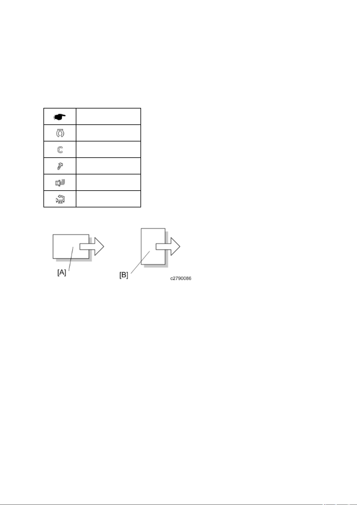
Symbols and Trademarks
Symbols
This manual uses several symbols. The meanings of those symbols are as follows:
See or Refer to
Clip ring
E-ring
Screw
Connector
Clamp
[A]: Short Edge Feed (SEF)
[B]: Long Edge Feed (LEF)
Trademarks
Microsoft®, Windows®, and MS-DOS® are registered trademarks of Microsoft Corporation in the
United States and /or other countries.
®
PostScript
®
PCL
Ethernet
PowerPC
is a registered trademark of Adobe Systems, Incorporated.
is a registered trademark of Hewlett-Packard Company.
®
is a registered trademark of Xerox Corporation.
®
is a registered trademark of International Business Machines Corporation.
Other product names used herein are for identification purposes only and may be trademarks of
their respective companies. We disclaim any and all rights involved with those marks.

PRODUCT INFORMATION
REVISION HISTORY
Page Date Added/Updated/New
None


Product
1. PRODUCT INFORMATION
Specifications
1.1 SPECIFICATIONS
See "Appendices" for the following information:
Main Frame
Supported Paper Sizes
Software Accessories
Optional Equipment
Information
SM 1-1 C279
Overview
1.2 OVERVIEW
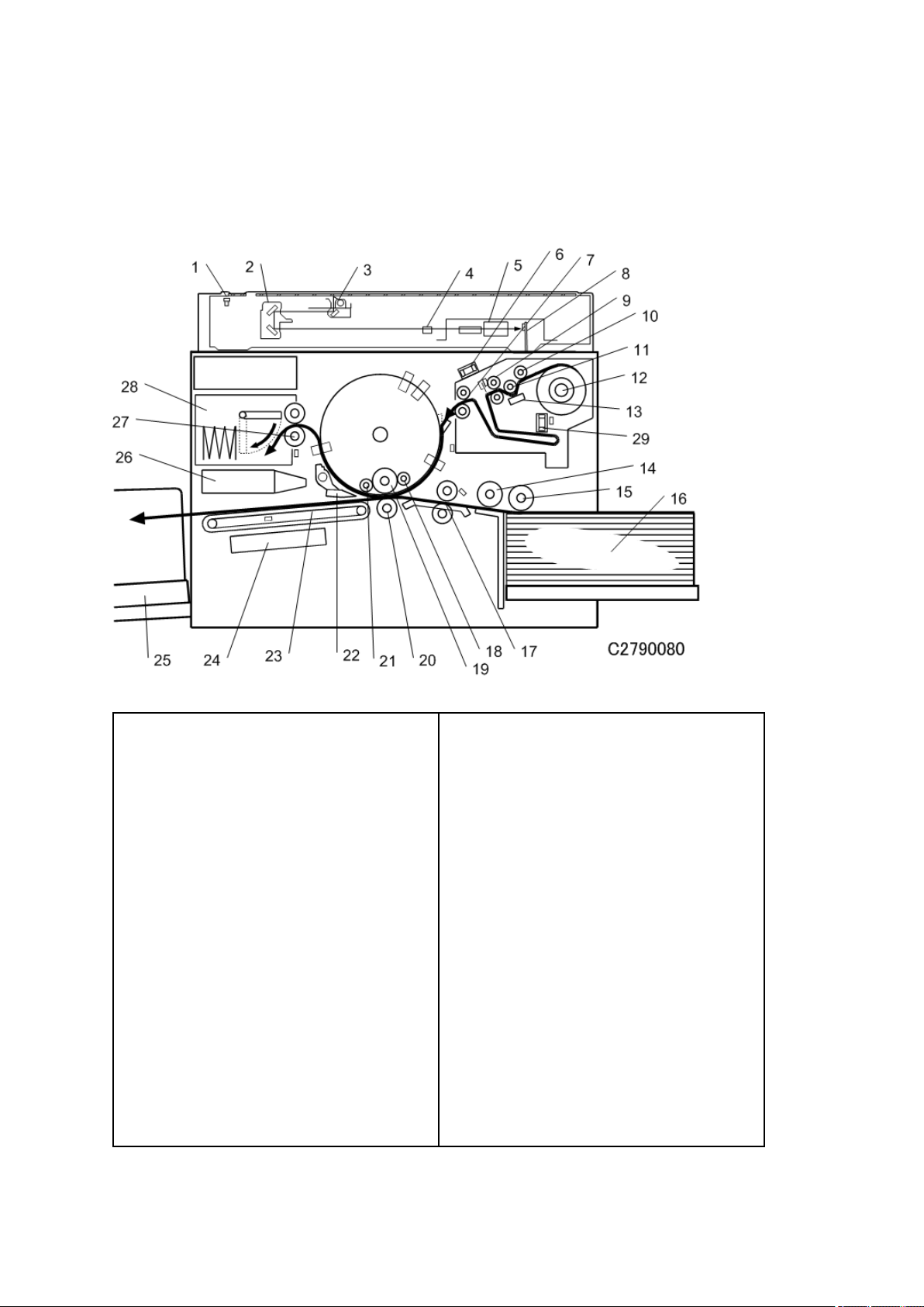
1.2.1 COMPONENT LAYOUT
1. Scanner HP sensor
2. 2nd carriage
3. 1st carriage
4. Original length sensor
5. Lens
6. Blower fan motor
7. Reverse roller
8. SBU
9. Tension roller
10. Master set roller
11. Platen roller
12. Master roll
13. Thermal head
14. Paper separation roller
15. Paper feed roller
16. Paper table
17. Registration rollers
18. Doctor roller
19. Ink roller
20. Press roller
21. Idling roller
22. Exit pawl
23. Transport belts
24. Vacuum fan motor
25. Paper delivery table
26. Air knife fan motors
27. Master eject rollers
28. Master eject box
29. Vacuum fan motor
C279 1-2 SM
Product
1.2.2 ELECTRICAL COMPONENT LAYOUT
Overview
Information
SM 1-3 C279

Overview
C279 1-4 SM
Product
Boards
No. Component Function
Overview
Information
6 CCD and SBU Outputs a video signal to the MPU.
Paper Width Detection Board Sends data about the paper width on the paper
18
table to the MPU.
30 Ink Detection Board Checks if there is ink in the drum.
36 Operation Panel Boards These boards control the operation panel.
37 Power Supply Unit (PSU) Provides dc power to the machine.
54 Main Motor Board Controls the main motor speed.
Main Processing Unit (MPU) Controls all machine functions, both directly and
62
through other boards.
70 Lamp Stabilizer This supplies power to the exposure lamp.
Motors
No. Component Function
5 Scanner Motor Drives the scanner.
23 Master Feed Motor Feeds the master to the drum.
24 Table Motor Raises and lowers the paper table.
SM 1-5 C279

Overview
No. Component Function
28 Printing pressure motor Raises and lowers the pressure roller.
31 Ink Pump Motor Drives the ink pump.
45 Master Eject Motor Sends used masters into the master eject box.
46 Air Knife Fan Motor 1
47 Air Knife Fan Motor 2
Rotates the fan to provide air to separate the
leading edge of the paper from the drum.
48 Air knife fan motor 3
Provides suction so that paper is held firmly on the
50 Vacuum Fan Motor
transport belt.
40 Paper Delivery Motor Feeds out the printed paper.
53 Pressure Plate Motor Raises and lowers the pressure plate.
57 Main Motor Rotates the drum.
Feeds the paper to align it with the master on the
59 Registration Motor
drum.
61 Paper Feed Motor Feeds the paper from the paper table.
67 Clamper Motor Opens or closes the master clamper on the drum.
72 Duct plate motor
Opens or closes the duct plate at entrance of the
duct.
74 Cutter Motor Cuts the master.
79 Duct fan motors Provides suction to guide the master into the duct.
81 Master Feed Motor Feeds the master to the drum.
83 Thermal head driving motor Raises and lowers the thermal head.
84 Blower fan motor Provides air to separate the master.
Presses or releases the drum idling roller against
91 Idling roller motor
the drum screen.
96 Ink Pump Motor Drives the ink pump.
C279 1-6 SM

Product
Sensors
No. Component Function
Overview
1 Scanner HP Sensor
Detects when the image sensor is at home
position.
Detects whether the platen cover is open or
3 Platen Cover Sensor
closed.
Detect the length of the original on the exposure
4 Original length sensor 1, 2
glass.
13 Master Set Cover Sensor Checks if the master set cover is properly set.
Detects when the master making unit runs out of
14 Master End Sensor
master roll.
Detects when the paper table reaches the paper
17 Paper Height Sensor
feed position.
19 Paper Length Sensor Detects when long paper is on the paper table.
20 Paper End Sensor Detects when the paper table runs out of paper.
Information
21 Registration Sensor Detects paper approaching the registration roller.
26 2nd drum master sensor Detects if there is a master on the drum.
Detects when the printing pressure is at the home
29 Printing pressure HP sensor
position.
39 Front Door Switching Sensor Detects if the Front Cover is in the closed position.
41 Master Eject Sensor Detects used master misfeeds.
42 Drum Master Sensor Detects if there is a master on the drum.
Detects when the pressure plate is at the home
43 Pressure Plate HP Sensor
position.
Detects when the pressure plate is in the lowest
44 Pressure Plate Limit Sensor
position.
49 Paper Exit Sensor Detects paper misfeeds at the exit.
SM 1-7 C279

Overview
No. Component Function
55 2nd Feed Timing Sensor
Determines the paper misfeed check timing at the
paper registration area.
58 Feed Start Timing Sensor Determines the paper feed start timing.
Detects when the paper table is at its lower limit
60 Table Lower Sensor
position.
Master Eject Position (Drum
Detects when the drum is at the master eject
63
HP) Sensor
position.
64 Paper Exit Timing Sensor Determines the paper exit misfeed check timing.
65 Clamper Closed Sensor Detects if the clamper is in the closed position.
66 Clamper Open Sensor Detects if the clamper is in the open position.
Detects when the duct plate is at the home
71 Duct plate HP sensor
position.
73 Cutter HP Sensor Detects when the cutter is at the home position.
76 Master Set Cover Sensor Checks if the master set cover is properly set.
Detects when the master making unit runs out of
77 Master End Sensor
master roll.
80 Duct jam sensor Detects when a master remains in the duct.
Detects when the thermal head is at the home
82 Thermal head HP sensor
position.
85 Master edge sensor Detects the leading edge of the master.
94 Ink idling roller HP sensor Detects when the idling roller is at home position.
C279 1-8 SM

Product
Solenoids
No. Component Function
Overview
Front Pressure Release
Releases the press roller to apply printing
27
Solenoid
Rear Pressure Release
pressure.
Releases the press roller to apply printing
56
Solenoid
pressure.
Switches
No. Component Function
Master Making Unit Set
16
Checks if the master making unit is installed.
Switch
22 Table Lowering Switch Lowers the paper table.
32 Door Safety Switch Checks whether the front door is properly closed.
35 Main Switch Turns the power on or off.
Information
Checks if the master making unit is installed.
38 Plotter Safety Switch
Note: The master making unit is sometimes
called the ‘plotter unit’.
52 Eject Box Set Switch Checks if the master eject box is installed.
68 Auto Off Switch Turns the power off automatically.
69 Master Eject Safety Switch Checks if the master eject unit is installed.
78 Lower master tray set switch Checks if the lower master tray is installed.
Counters
No. Component Function
33 Paper Counter Keeps track of the total number of copies.
34 Master Counter Keeps track of the total number of masters made.
SM 1-9 C279

Overview
Others
No. Component Function
2 Exposure Lamp (Xenon Lamp) Applies light to the original for exposure.
15 Thermal Head Burns the image onto the master.
Drum home position indicator
LEDs that indicates the drum position.
25
(LEDs)
Drum thermistor Detects the temperature inside the drum to adjust
92
various processes.
93 Ink detection pins Detect if ink is present in the drum
C279 1-10 SM
Product
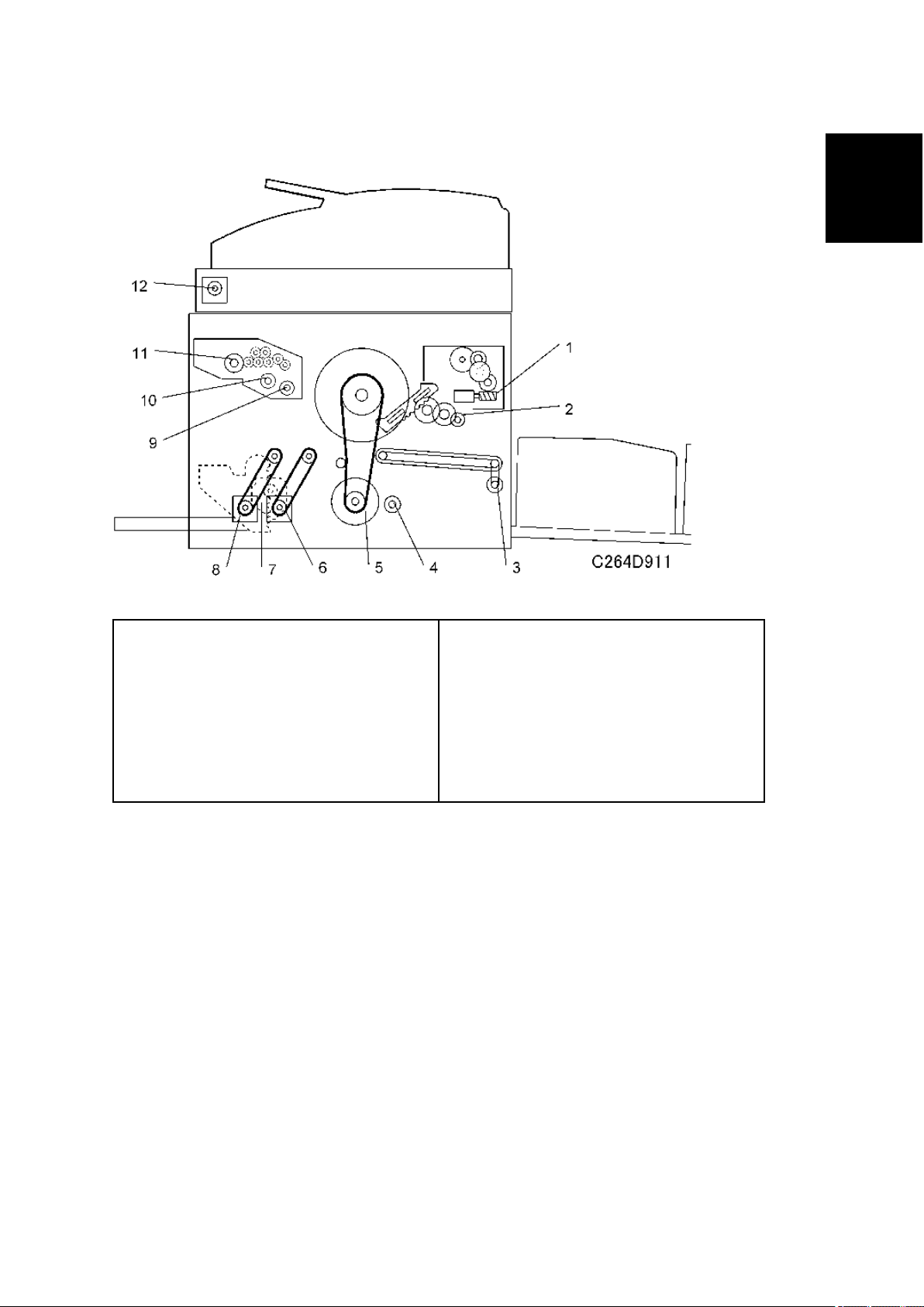
1.2.3 DRIVE LAYOUT
Overview
Information
1. Pressure plate motor
2. Clamper motor
3. Paper delivery motor
4. Printing pressure motor
5. Main motor
6. Registration motor
7. Table motor
8. Paper feed motor
9. Duct plate motor
10. Thermal head driving motor
11. Master feed motor
12. Scanner motor
SM 1-11 C279

Machine Codes and Peripherals Configuration
1.3 MACHINE CODES AND PERIPHERALS
CONFIGURATION
No Item Machine Code Remarks
C279
1 Mainframe
2 Platen Cover D593
3 Auto Document Feeder D578
4 Network Controller C654
5 Tape Dispenser C651
6 Optional Drum C618/C619/C620
-11/-17/-27/-29
-61/-65
One from No.2 or No.3
C279 1-12 SM
 Loading...