

Page 1

Slide 1
D392 Ring Binder Training
V-C3 TECHNICAL TRAINING
OPTIONAL RING BINDER (D392)
No additional notes
1
Page 2

Slide 2
D392 Ring Binder Training
Overview
No additional notes
2
Page 3
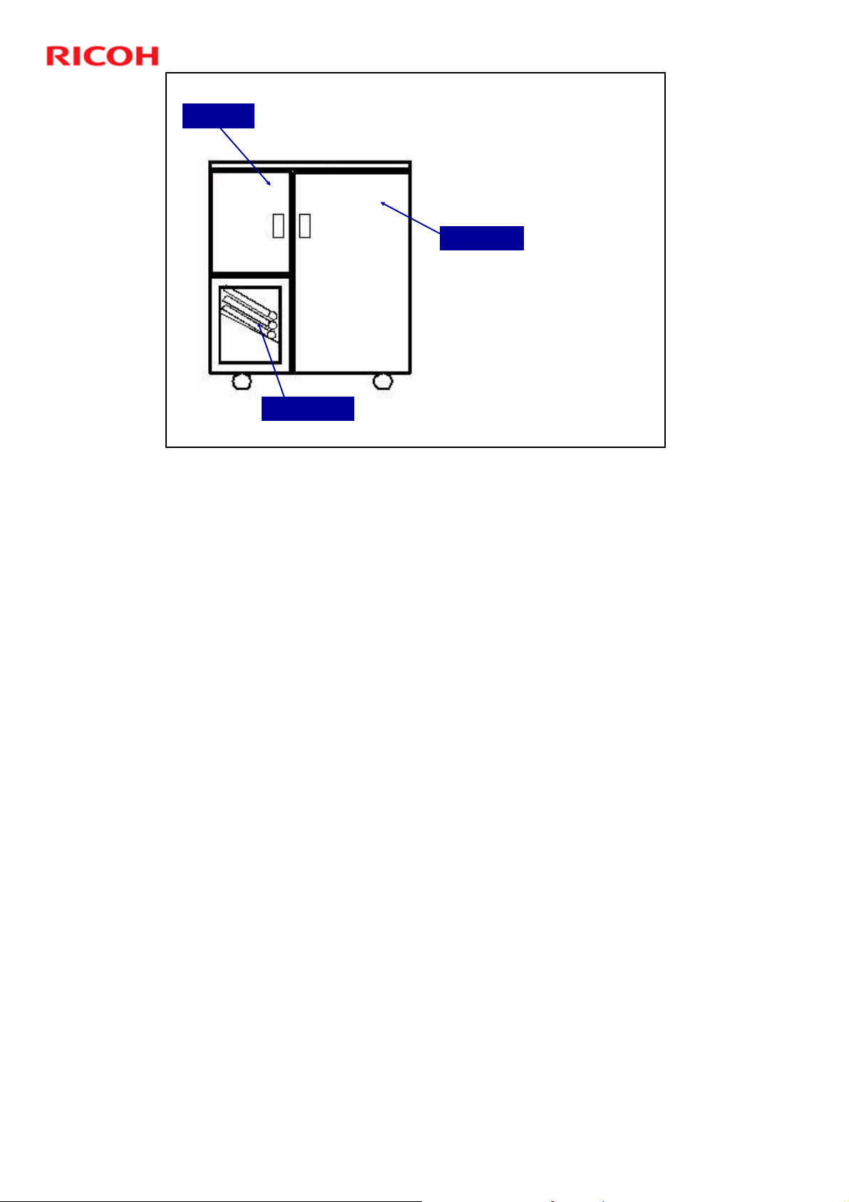
D392 Ring Binder Training
Left Door
Slide 3
External View
Do not use the empty
space below the output
tray as a storage area.
Right Door
Output Tray
D392 service manual, Details, Overview, Important Parts
3
Page 4
D392 Ring Binder Training
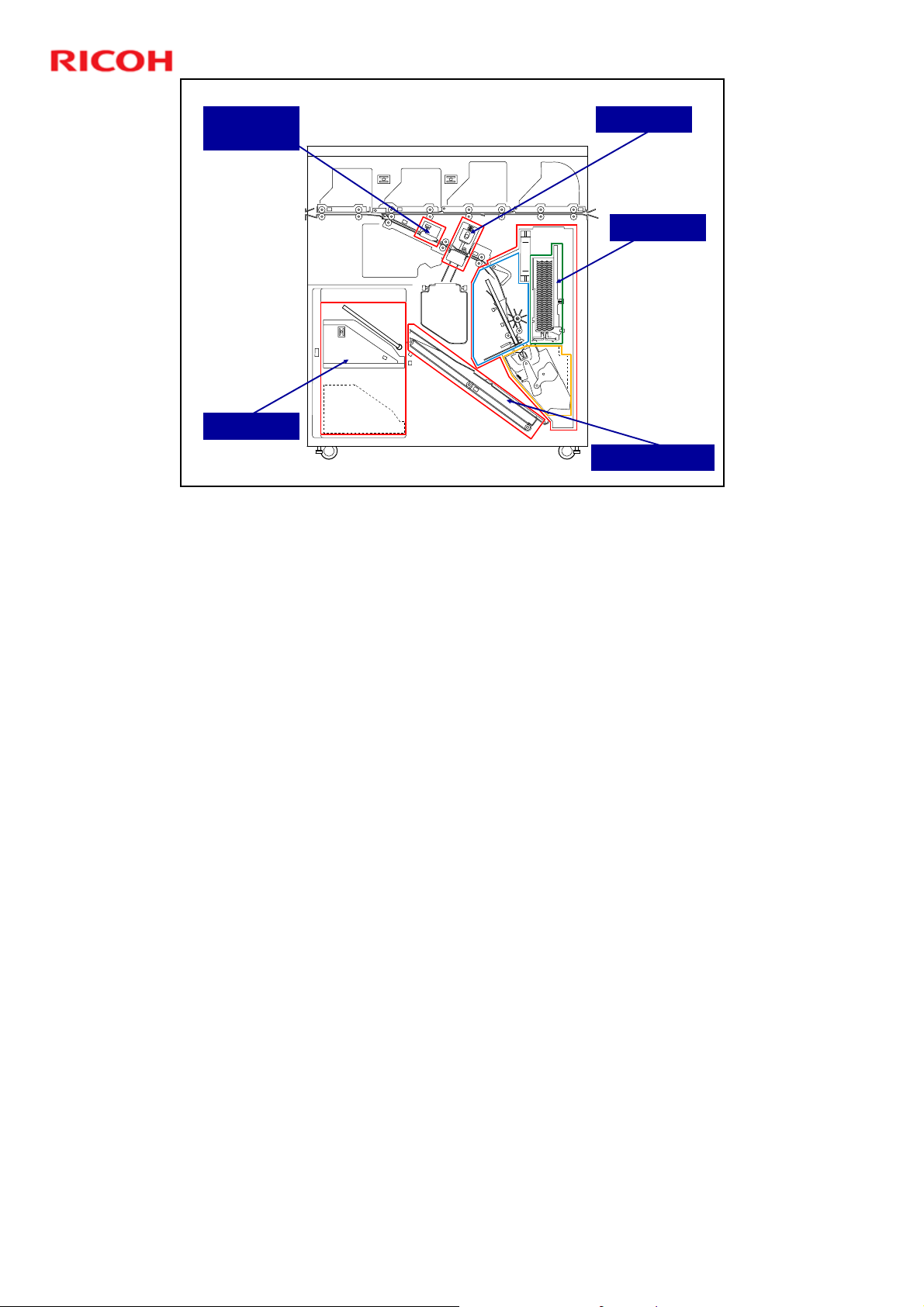
Pre-Punch
Jogger Unit
Stacker Unit
Slide 4
Main Units
Punch Unit
Binder Unit
Output Belt Unit
D392 service manual, Details, Overview, Important Parts
The binder unit contains the pre-bind jogger unit, ring supply unit, and clamp unit.
See the service manual for the locations of these within the binder unit.
4
Page 5

Slide 5
D392 Ring Binder Training
Inform the Customers
The next few slides contain points to tell the customers after you finish the
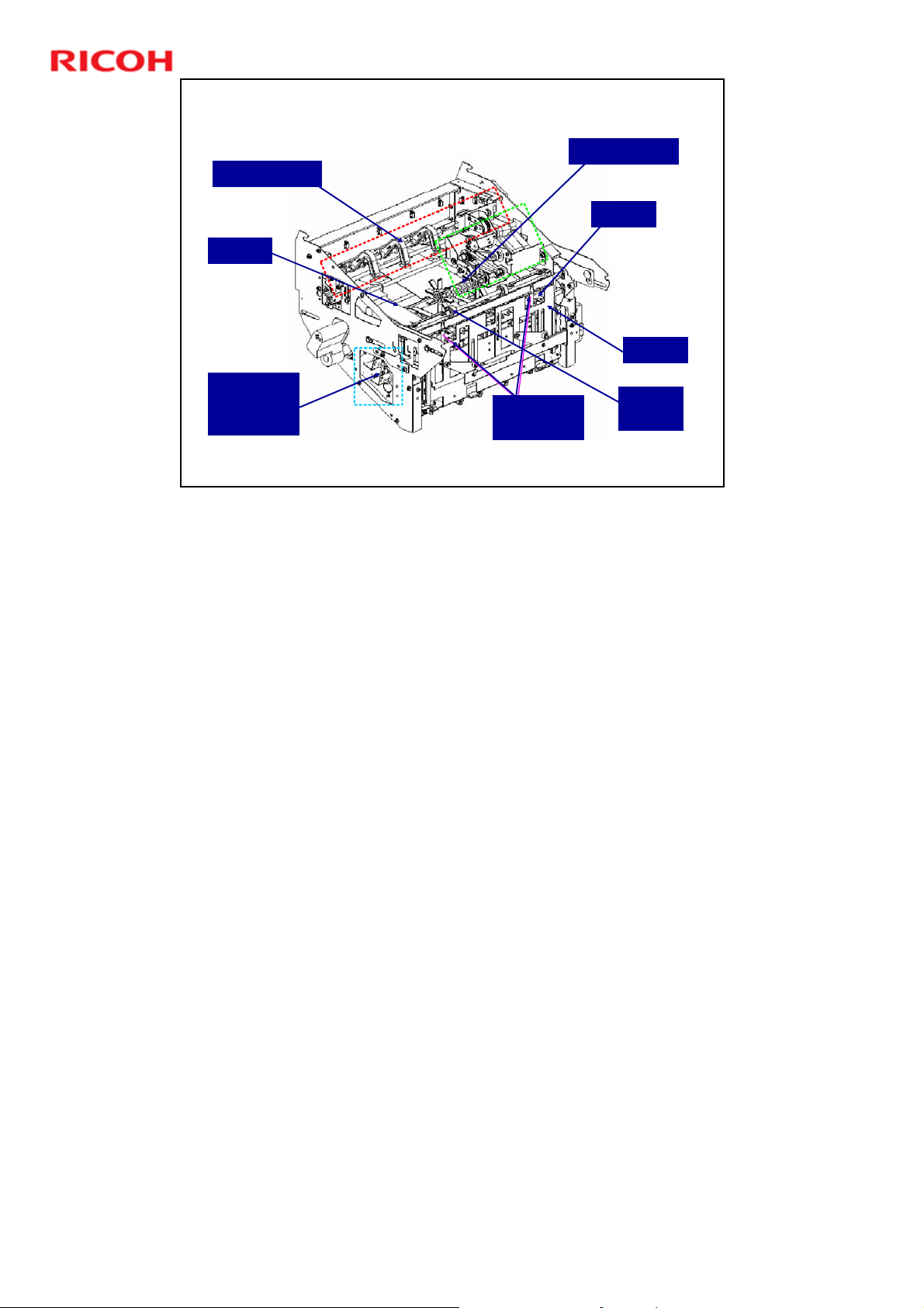
installation.
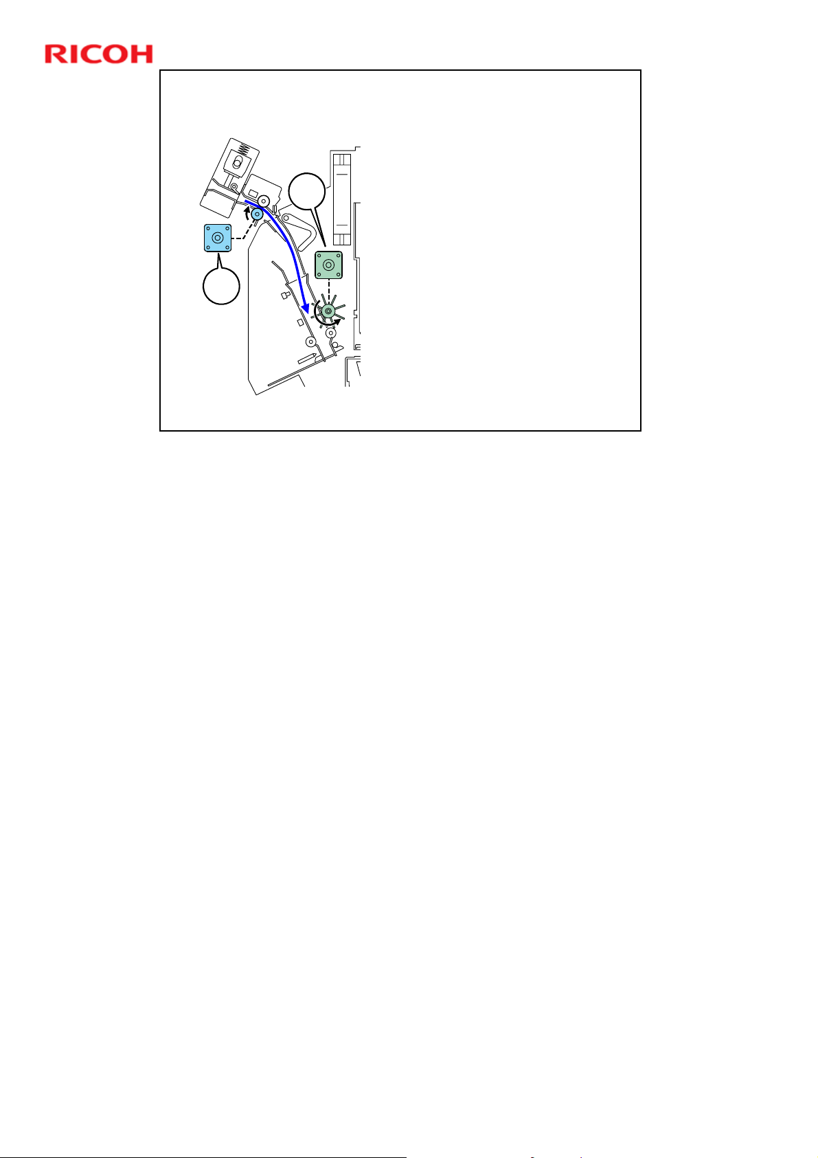
5
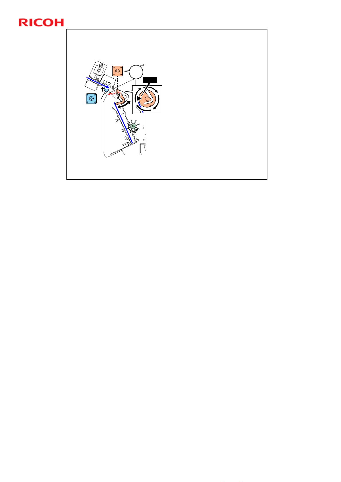
Page 6

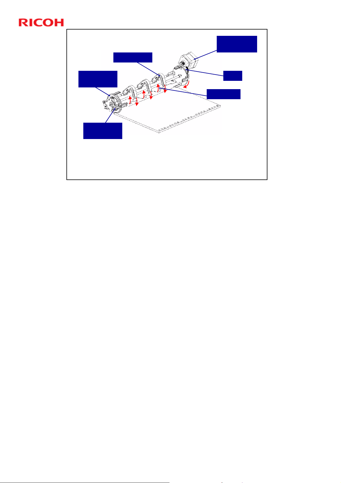
Jams
Decals attached to the machine that provide
guidance for removing paper jams. Point out the
decal locations.
Detailed instructions on removing ring jams are
provided in the operating instructions under
"Removing Jammed Ring Combs".
Slide 6
D392 Ring Binder Training
No additional notes
6
Page 7
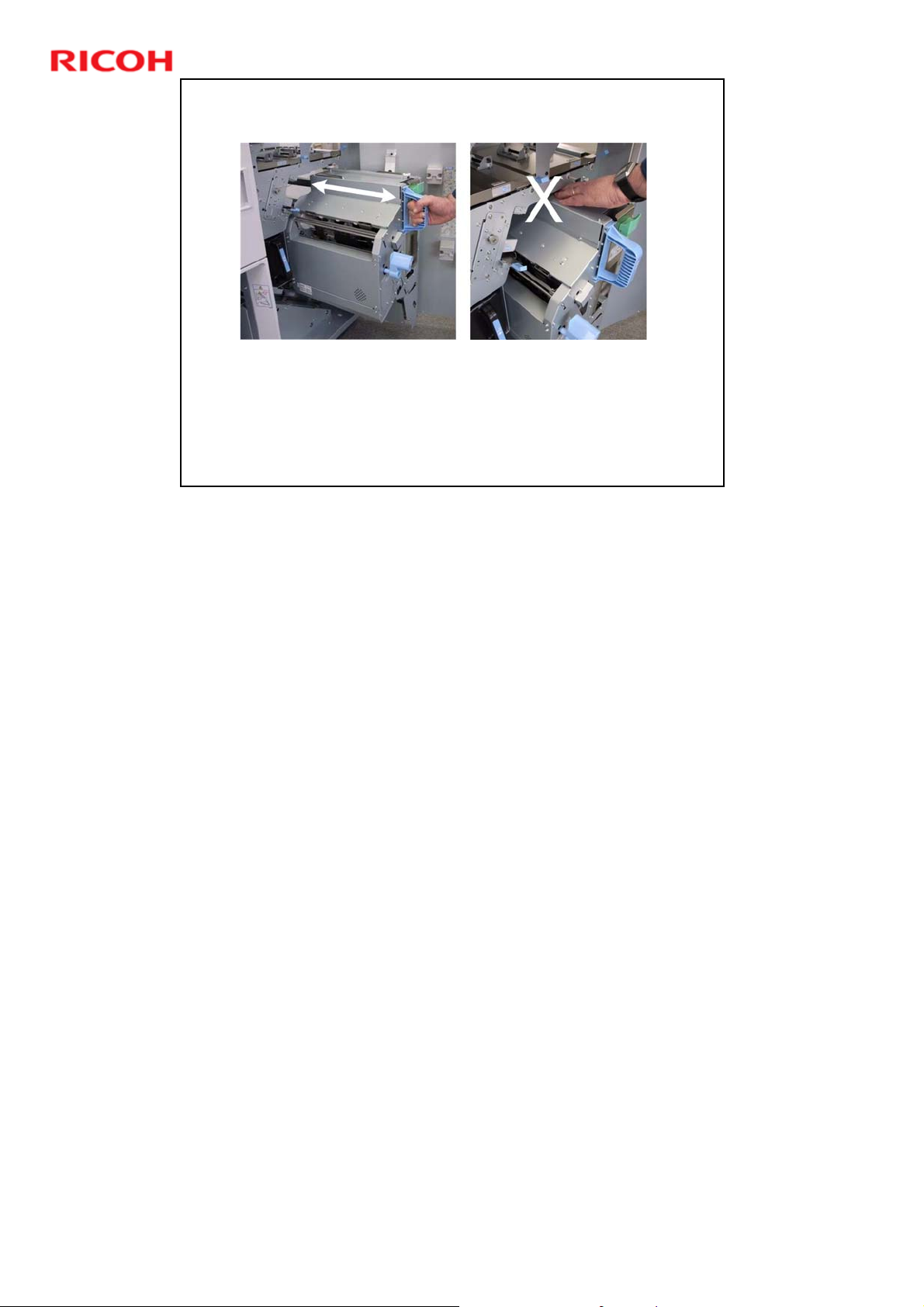
Pulling out/Pushing in the Binder Unit
Always grip handle Mc8 when pulling out or pushing in the binder
unit.
Never touch any other surface of the binder unit when it is
moving.
To avoid injury the fingers, never push on the top of the binder
unit to slide it back into the finisher.
Slide 7
D392 Ring Binder Training
No additional notes
7
Page 8
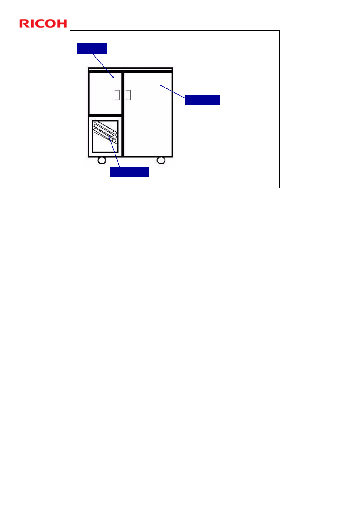
Left Door
Slide 8
D392 Ring Binder Training
Do not Store Things Below the
Output Tray
Do not use the empty
space below the output
tray as a storage area.
Right Door
Output Tray
D392 service manual, Details, Overview, Important Parts
Obstacles in this area (circled in the illustration) will interfere with the raising and
lowering of the tray and cause an error.
8
Page 9
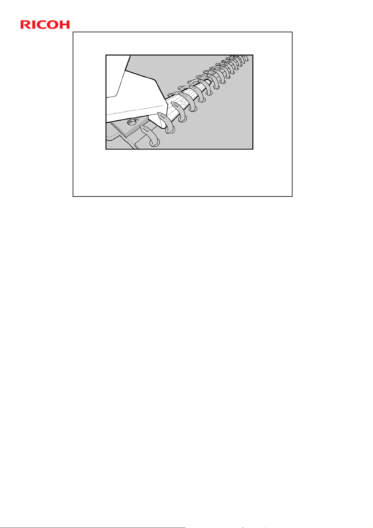
Ring Opener
The customer can use this to add pages to a document that
is already bound.
The additional pages must be printed with punching only
(no ring binding).
Slide 9
D392 Ring Binder Training
The ring binder is limited to 100 pages.
If the customer needs to bind a 120-page document:
First, do a run of 100 pages with ring binding enabled.
Then, do a 20-page run for the remaining pages, with punching only (no ring
binding).
Then, use the ring opener to open the ring and add the remaining pages to the
completed document.
For details about the ring opener, see the Operating Instructions for the ring
binder.
Troubleshooting, Inserting Pages into an Existing Ring Bound
Booklet
9
Page 10

Slide 10
D392 Ring Binder Training
Machine Component Overview
No additional notes
10
Page 11
D392 Ring Binder Training
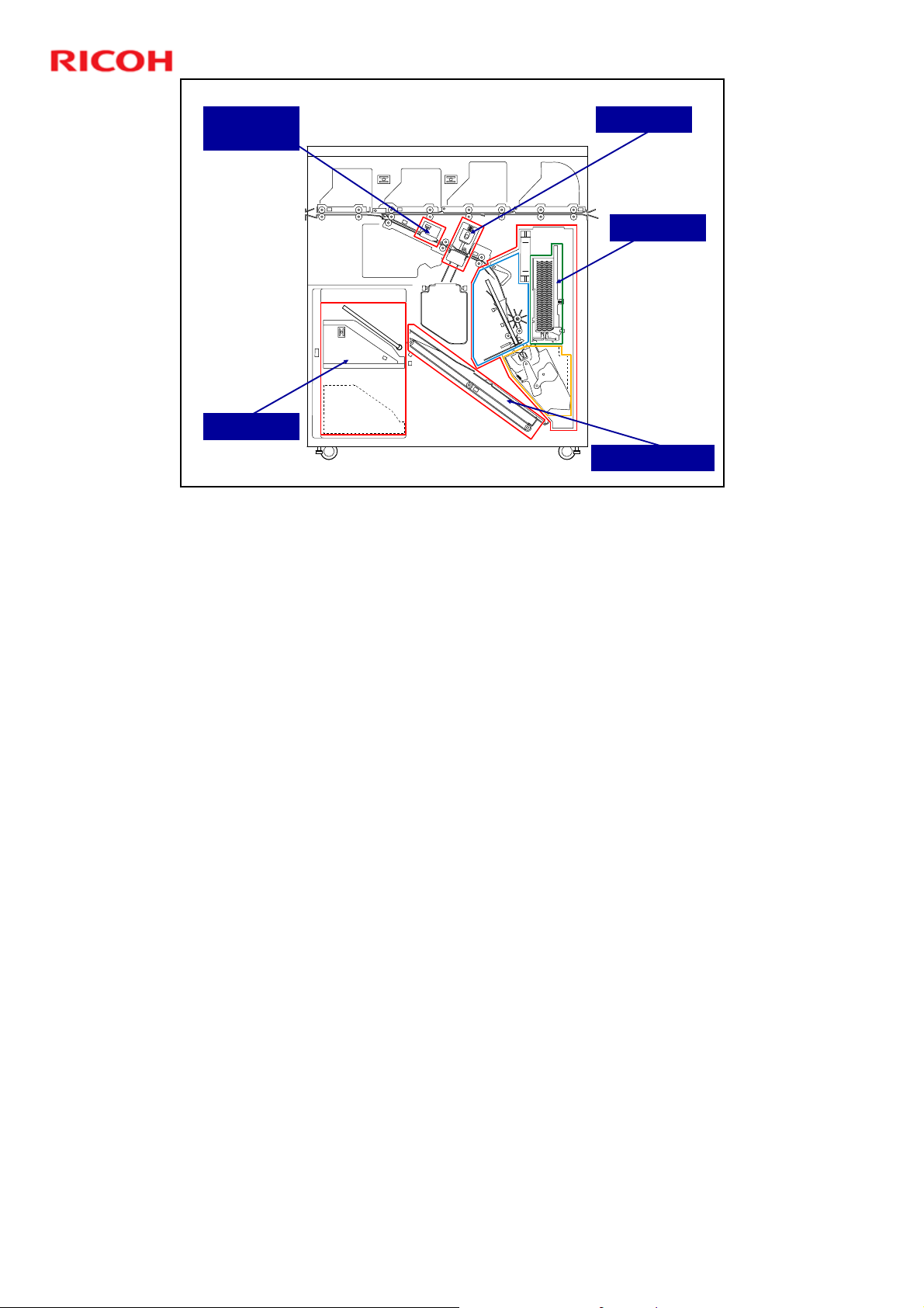
Pre-Punch
Jogger Unit
Stacker Unit
Slide 11
Main Units
Punch Unit
Binder Unit
Output Belt Unit
D392 service manual, Details, Overview, Important Parts
This is a repeat of the slide that we saw at the start of the course, just to refresh
your memory after that arduous installation procedure.
The binder unit contains the pre-bind jogger unit, ring supply unit, and clamp unit.
See the service manual for the locations of these within the binder unit.
11
Page 12
D392 Ring Binder Training
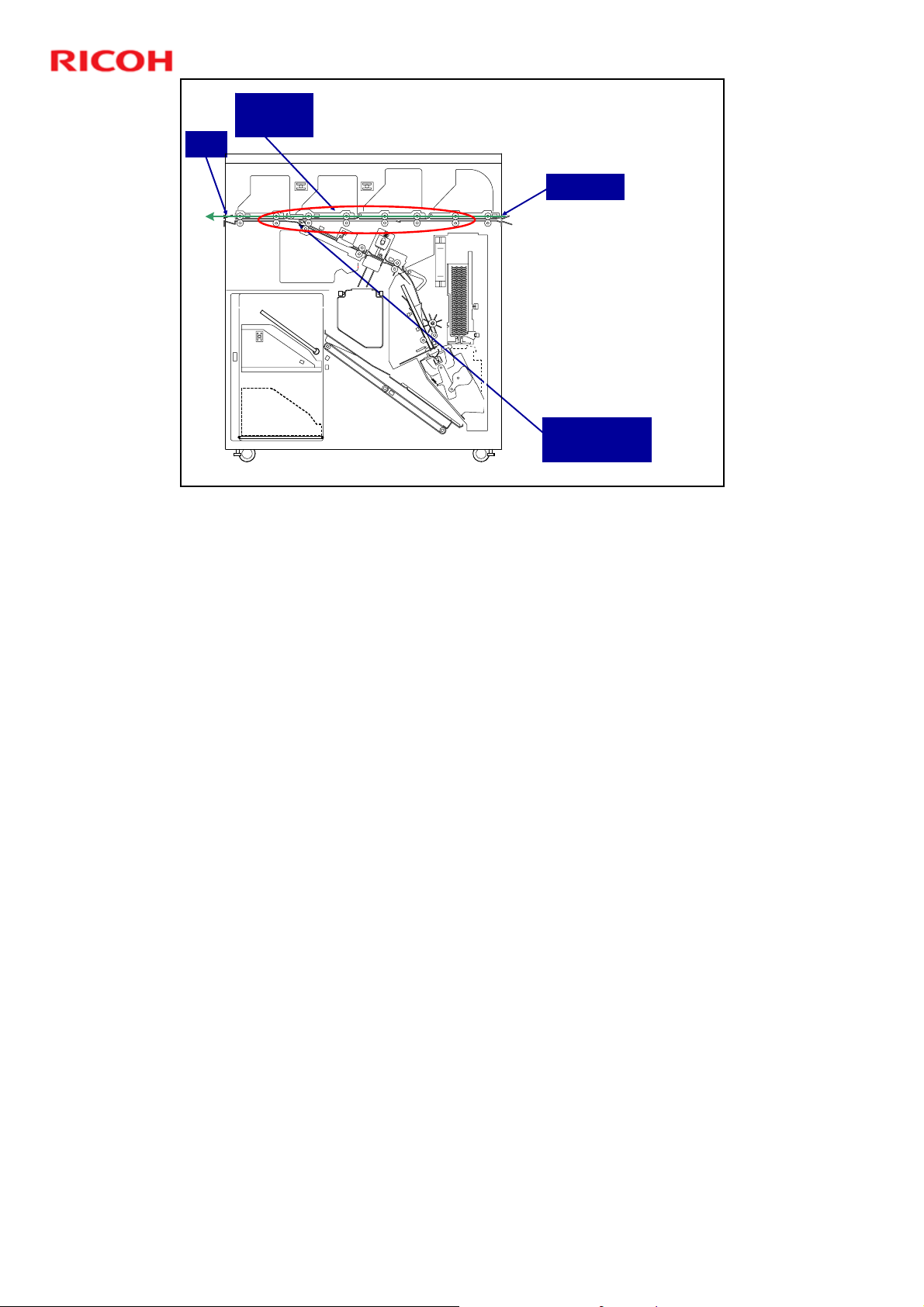
Exit
Slide 12
Transport
Rollers
Downstream Delivery
Paper Path
Entrance
The transport
rollers feed the
paper straight
through the top of
the machine.
The switchback
junction gate stays
in the ‘up’ position.
Switchback
Junction Gate
D392 service manual, Details, Overview, Paper Transport
This is how paper feeds through the finisher if ring binding is not selected for the
job.
12
Page 13

D392 Ring Binder Training
Transport
Rollers
Exit
Slide 13
Paper Path
Ring Binding - 1
The transport
rollers feed the
paper, until the
paper is part of the
way out of the exit.
Then, the exit
rollers stop, and the
switchback junction
gate lowers.
Switchback
Junction Gate
Exit Rollers
D392 service manual, Details, Overview, Paper Transport
The first phase is similar to downstream delivery, until the paper stops after the
leading portion of the paper is fed past the exit.
13
Page 14
D392 Ring Binder Training
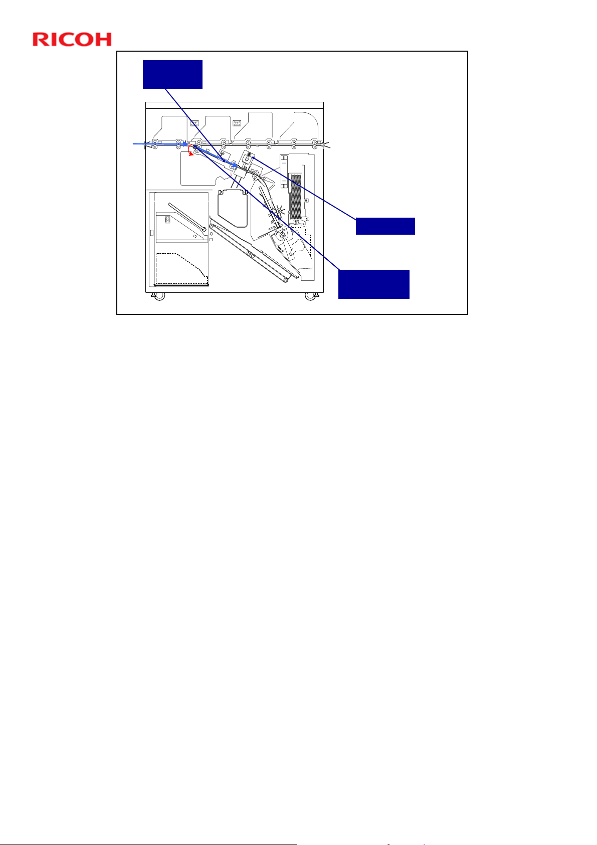
Pre-Punch
Jogger
Slide 14
Paper Path
Ring Binding - 2
D392 service manual, Details, Overview, Paper Transport
Now the paper is fed into the ring binder
The exit rollers feed
in reverse.
The switchback
junction gate sends
the paper to the prepunch jogger.
This aligns the
paper for
punching.
Punch Unit
Switchback
Junction Gate
14
Page 15
Slide 15
D392 Ring Binder Training
Paper Path
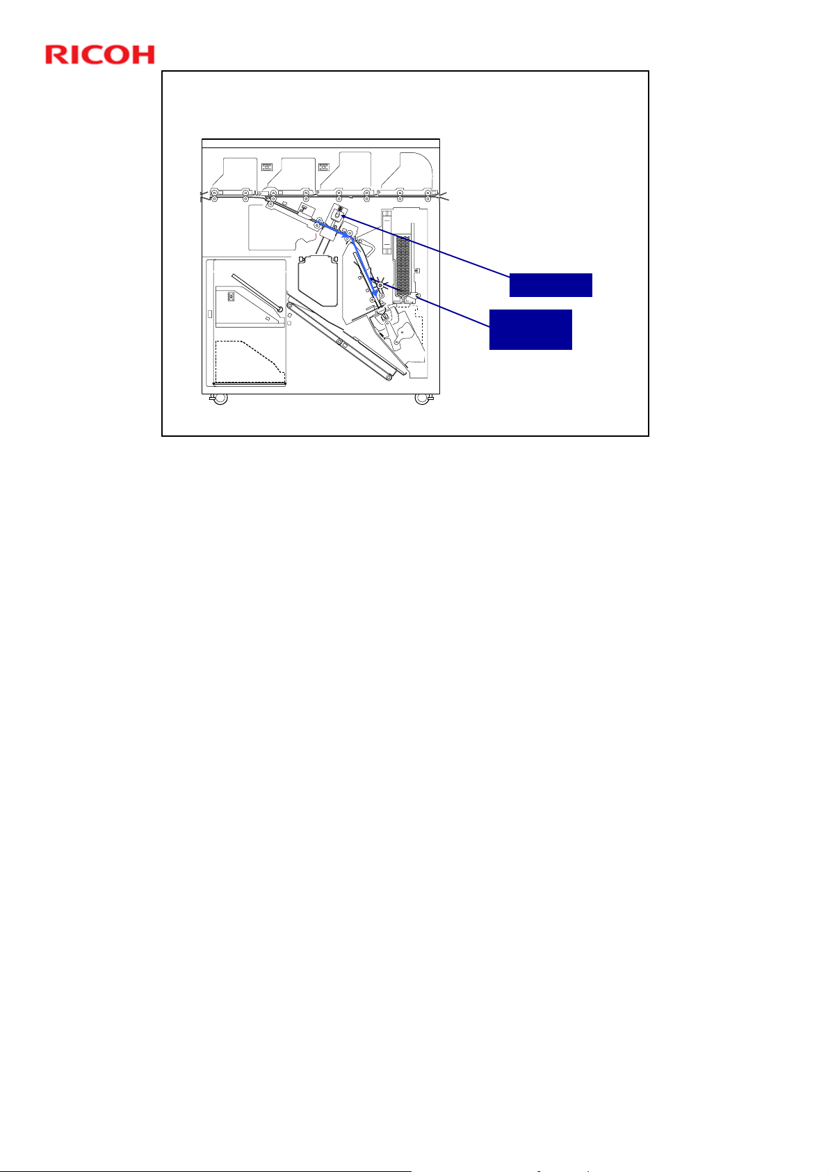
Ring Binding - 3
The punch unit
punches the paper
and sends it to the
pre-bind jogger.
This aligns the
paper for binding.
Punch Unit
Pre-Bind
Jogger
D392 service manual, Details, Overview, Paper Transport
Now the paper is fed into the ring binder
15
Page 16
Slide 16
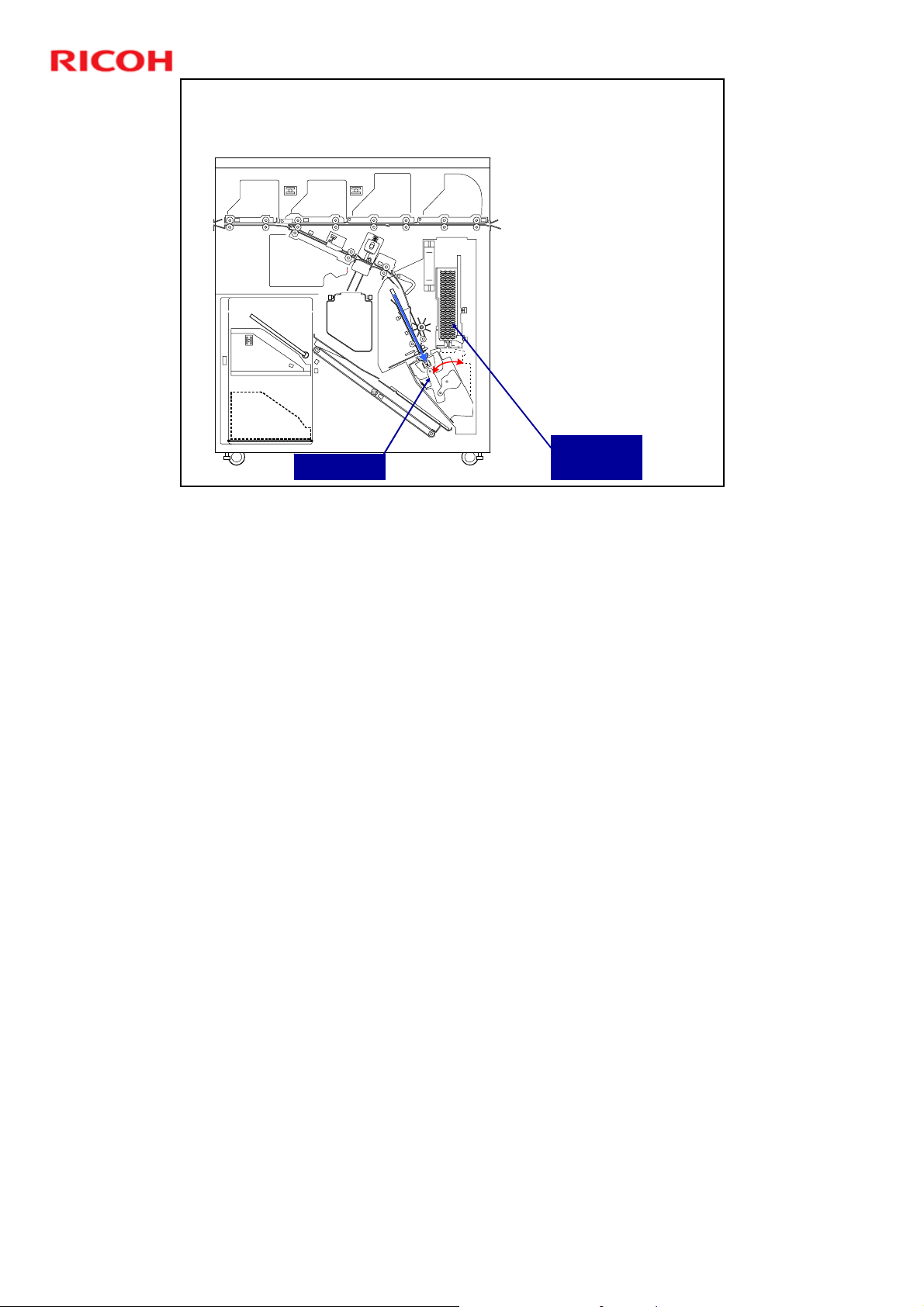
Ring Binding - 4
Clamp Unit
D392 Ring Binder Training
Paper Path
The binding unit
swings to the left to
catch the stack.
The stack feeds
forward a short
distance, so that the
leading edge enters
the top of the binder
unit.
In the binding unit, the
clamp unit takes one
ring from the cartridge
and clamps it through
the punched holes in
the stack.
Then the clamp unit
moves back to the
vertical position.
Ring
Cartridge
D392 service manual, Details, Overview, Paper Transport
Now the paper is fed into the ring binder.
The red arrow indicates the movement of the clamp unit in the binder unit.
16
Page 17
Paper Path
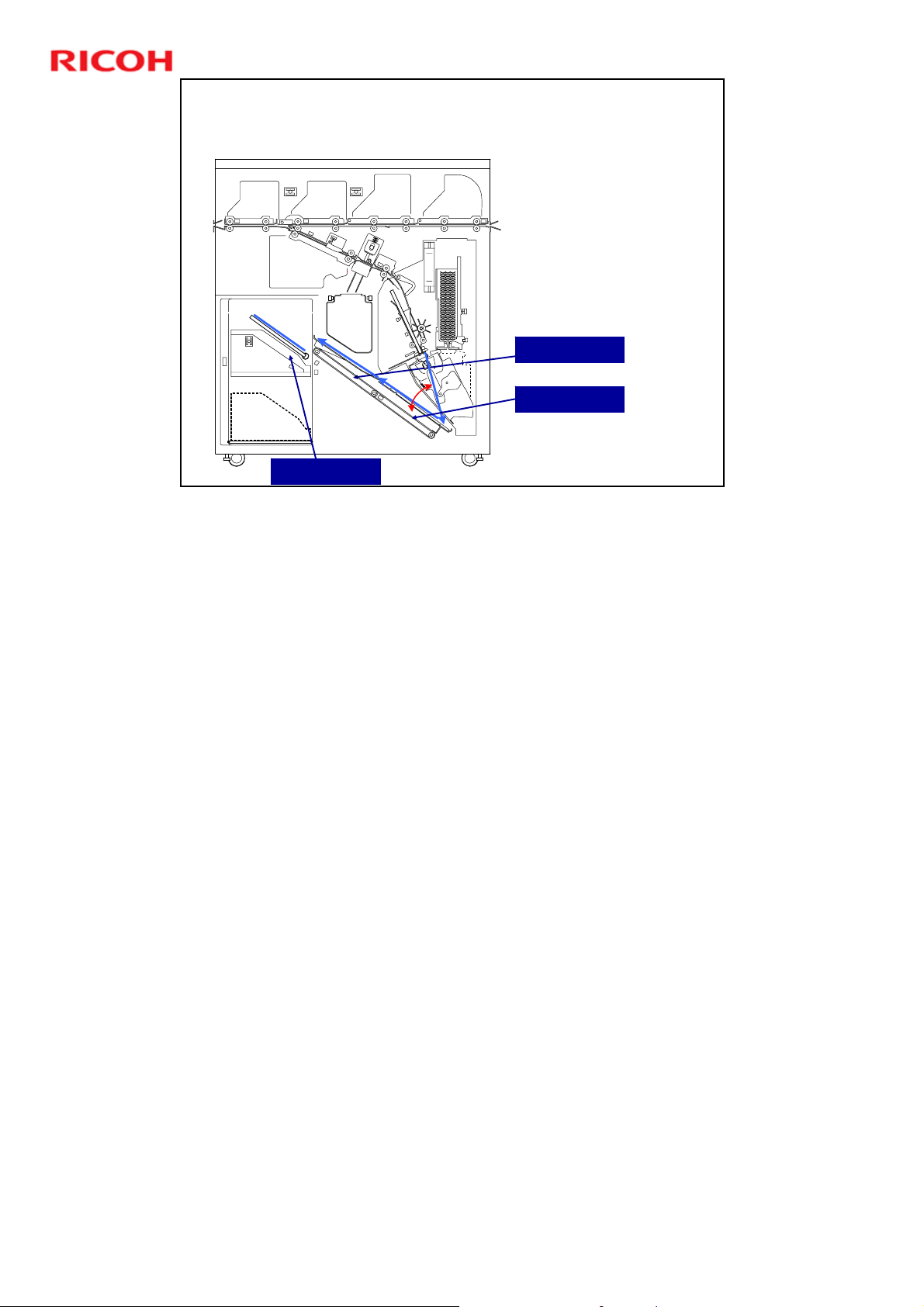
Ring Binding - 5
Output belt 1 moves
Output belts 1 and 2
Output Belt 2
Output Belt 1
D392 Ring Binder Training
up to catch the
bound stack. Then
it moves down to
the same level as
output belt 2.
then feed the stack
to the stacking unit.
Slide 17
Stacking Unit
D392 service manual, Details, Overview, Paper Transport
The red arrow indicates the movement of output belt 1 to catch the paper.
17
Page 18

Slide 18
D392 Ring Binder Training
Paper Feed and Switchback
No additional notes
18
Page 19

Paper Feed
M201
D392 Ring Binder Training
M102
M103
M301
M101 (Entrance motor): Drives the entrance roller and the 1st
transport roller
M102 (Transport motor): Drives the 2nd, 3rd, 4th, and 5th
transport rollers
M103 (Exit motor): Drives the 6th transport roller and the exit
roller.
Feeds in reverse to feed the paper back into the machine for ring
binding.
Slide 19
M303
M101
D392 service manual, Details, Overview, Paper Feed and
Switchback
19
Page 20
Sensors
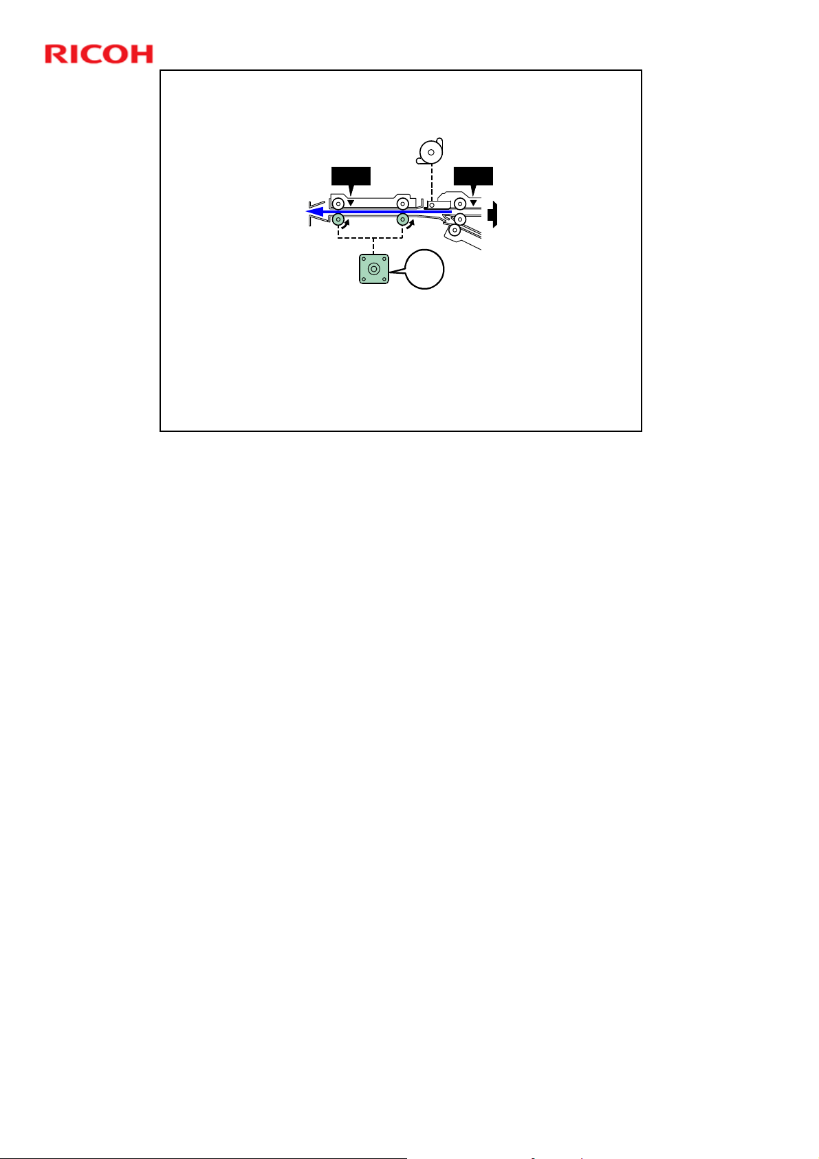
S103 S102
M103
S102 (Transport sensor) and S103 (Exit sensor) detect jams
in the feed path
Slide 20
D392 Ring Binder Training
No additional notes
20
Page 21
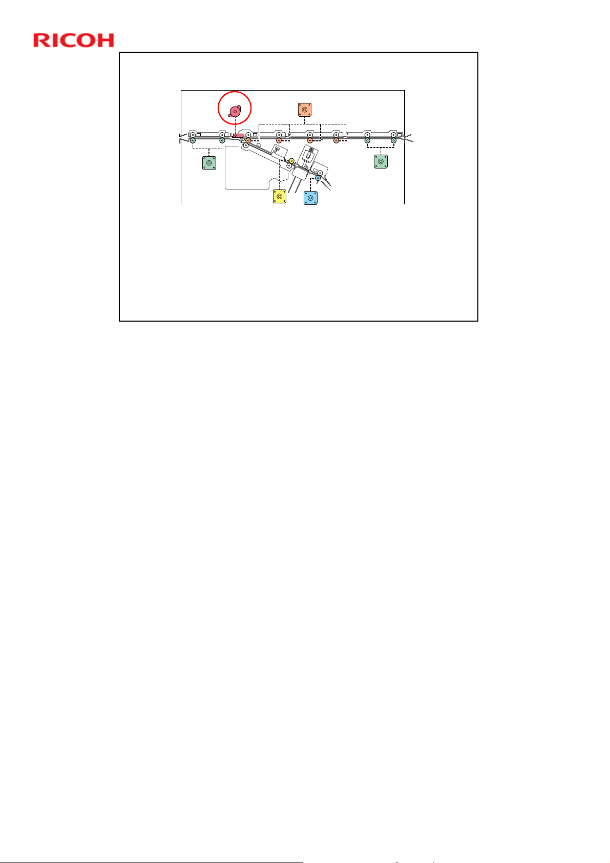
Switchback
M201
D392 Ring Binder Training
M102
M103
M301
M303
M101
M201 (Path JG Motor): Controls the switchback junction
gate.
A spring normally keeps the gate open so that paper can
feed through for downstream delivery.
Slide 21
D392 service manual, Details, Overview, Paper Feed and
Switchback
21
Page 22
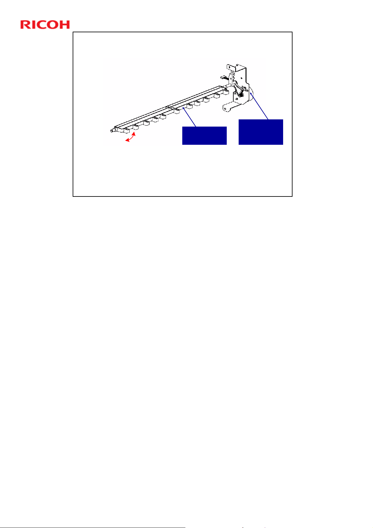
Switchback Junction Gate
Switchback
Junction Gate
M201 (Path JG Motor): Controls the switchback junction
gate.
A spring normally keeps the gate open so that paper can
feed through for downstream delivery.
Slide 22
D392 Ring Binder Training
M201 (Path
Junction Gate
Motor)
No additional notes
22
Page 23

Slide 23
D392 Ring Binder Training
Punching Holes in the Paper
No additional notes
23
Page 24
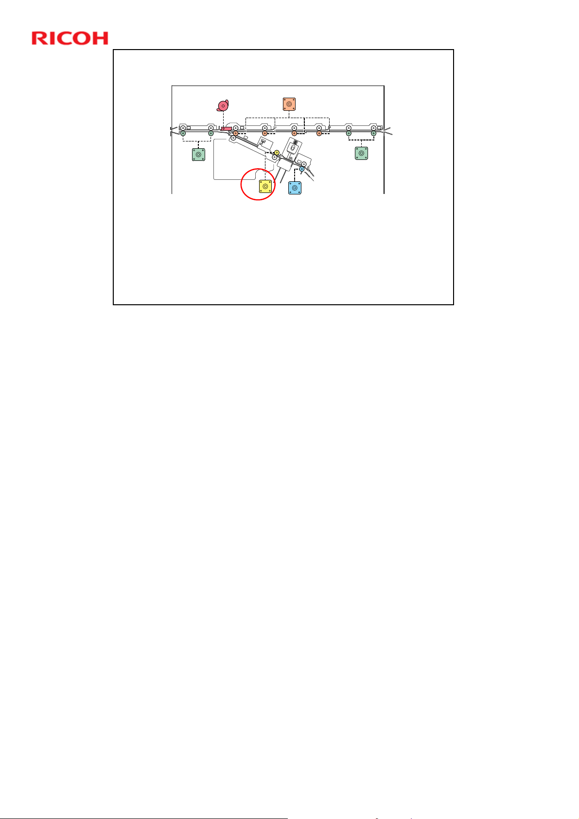
Pre-punch Jogging - 1
M201
M102
D392 Ring Binder Training
M103
M301
M303
M101
M301 (Jog Roller Motor): Controls the roller that feeds the
paper into the pre-punch jogger.
Slide 24
D392 service manual, Details, Overview, Paper Feed and
Switchback
24
Page 25

Slide 25
D392 Ring Binder Training
Pre-punch Jogging - 2
SOL302 (Top fence
solenoid): Controls the
stopper inside the punch
unit.
This stopper improves
the accuracy of hole
punching at the leading
edge of each sheet.
SOL
No additional notes
25
Page 26

Pre-punch Jogging - 3
S302
D392 Ring Binder Training
M305 (Jog roller lift motor): Makes a gap between the two
rollers to allow the paper to be moved from side to side
during jogging.
Slide 26
No additional notes
M305
M304
S303
26
Page 27
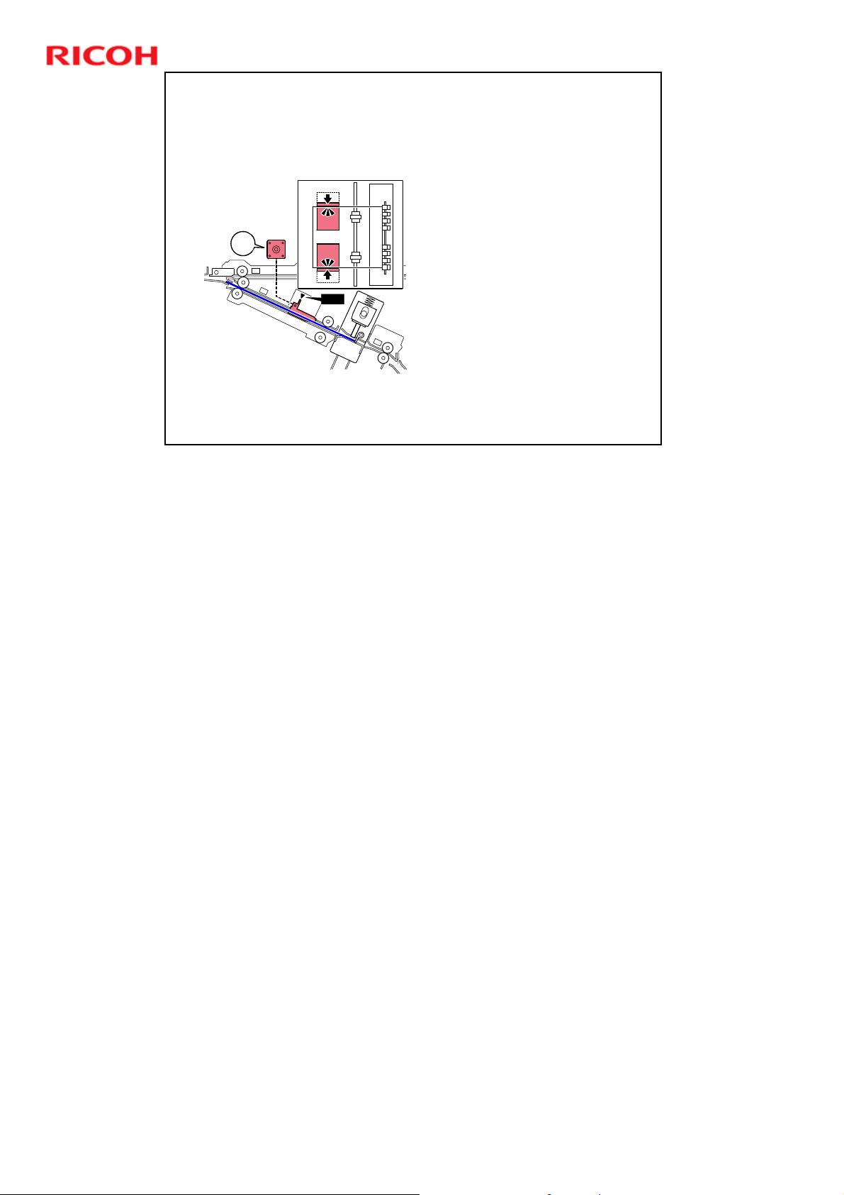
Slide 27
M302
D392 Ring Binder Training
Pre-punch Jogging - 4
M302 (Side jogger motor):
Controls the jogger
fences.
S301 (Pre-punch jogger
HP sensor): Detects when
the jogger fences are at
home position.
S301
No additional notes
27
Page 28
D392 Ring Binder Training
Paper Punching
Punch HP
Sensor
Knob
Stopper
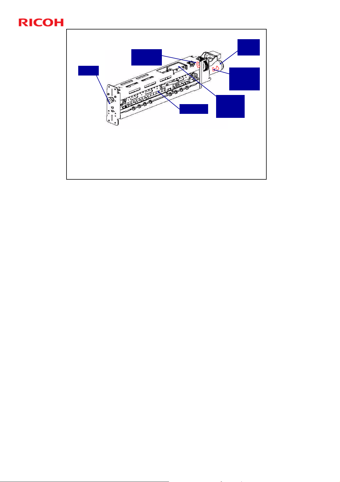
Two types of punch unit:
A4 (makes 23 holes)
LT (makes 21 holes)
The machine can detect which type of punch unit is installed.
The job will not execute if the punch unit if the paper size does not
match the punch unit type.
Slide 28
Top
Fence
Solenoid
Punch
Motor
Punch
Encoder
Sensor
The stopper and the top fence solenoid were discussed in a previous slide.
Use the knob to pull the punch unit out of the machine.
The machine comes with a punch unit for either A4 or LT, depending on the
area. If the customer wants the other punch unit, they can order it. They also
have to order ring cartridges for that paper size.
28
Page 29

Paper Punching
S302
D392 Ring Binder Training
M305
S303
M304 (Punch motor): Punches the holes in the paper.
Pages are punched one at a time
S303 (Punch HP sensor): Detects when the punch unit is at home
position. Also detects if the punch unit is missing.
S320 (Punch encoder sensor): Controls the start and stop timing,
and the speed of the punch motor.
Slide 29
M304
Punch motor speed is adjusted to match the thickness of the paper.
29
Page 30
Feed-out from the Punch Unit
M201
M102
D392 Ring Binder Training
M103
M301
M303
M101
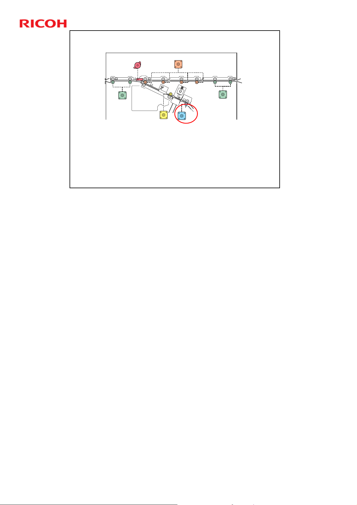
M303 (Punch Unit Runout Motor): Controls the roller that
feeds the paper out of the punch unit, and towards the prebind jogger unit.
Slide 30
D392 service manual, Details, Overview, Paper Feed and
Switchback
30
Page 31

Slide 31
D392 Ring Binder Training
Binder Unit
Overview
No additional notes
31
Page 32
D392 Ring Binder Training
Ring Supply
Unit
Pre-bind
Jogger Unit
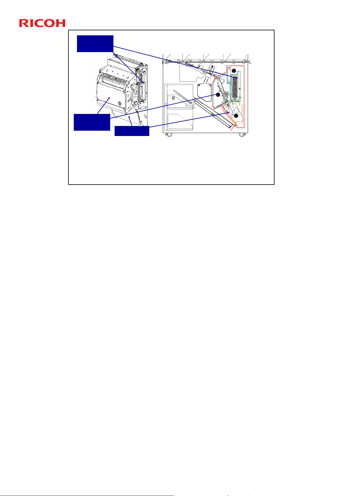
Pre-bind jogger unit: Jogs and stacks each punched sheet, to
align the stack for ring binding.
Ring supply unit: Holds the ring cartridge that feeds a single ring
to the clamp unit below.
Clamp unit: Takes a ring from the bottom of the ring cartridge and
Slide 32
swings right to insert the ring into the holes in the stack (the
stack is held in the pre-bind jog unit).
No additional notes
Binder Unit
2
1
3
Clamp Unit
32
Page 33

Slide 33
D392 Ring Binder Training
Binder Unit
Components of the Ring Supply Unit
No additional notes
33
Page 34
Locations of Components
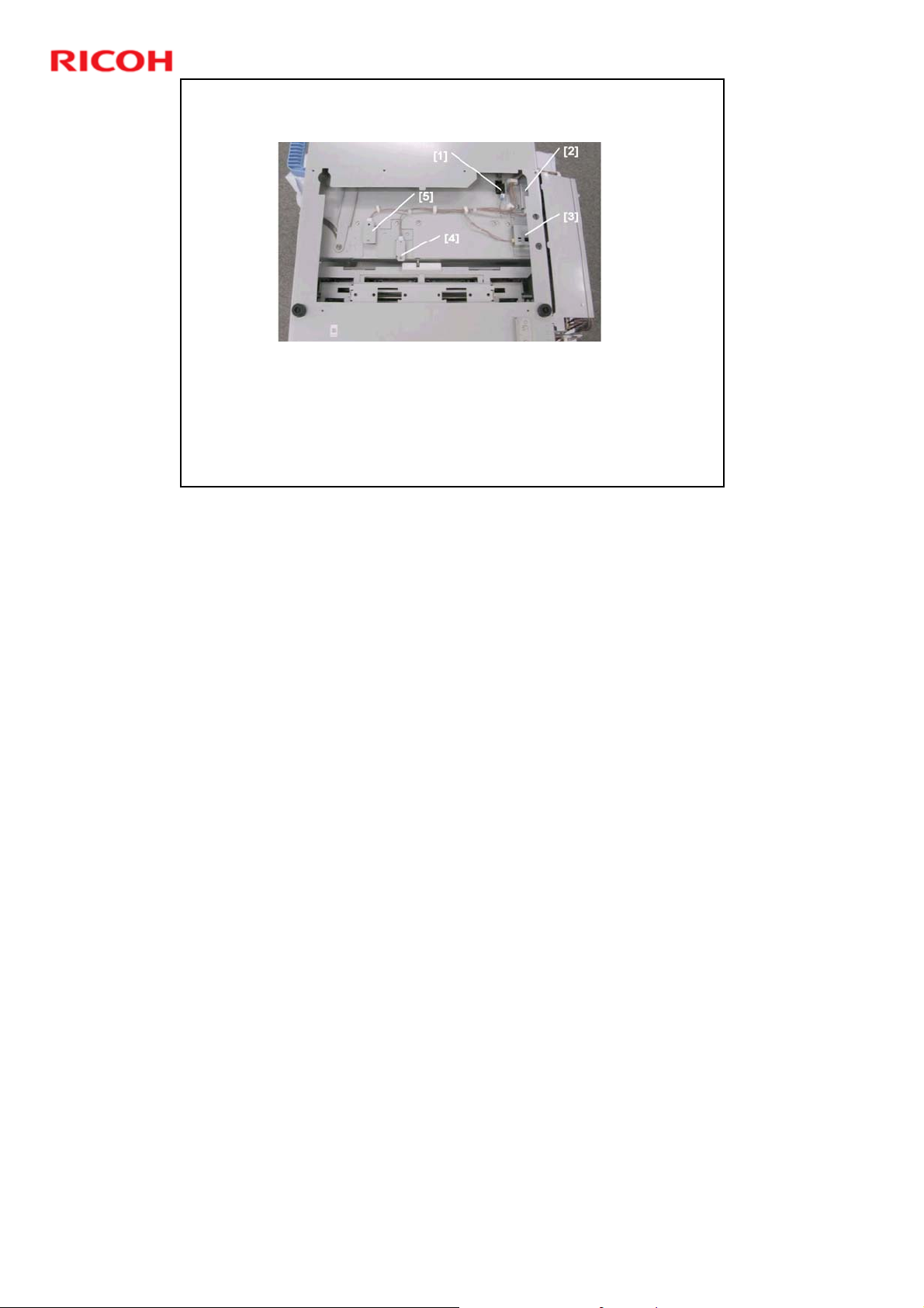
[1]: Cartridge Detection Sensor (S801)
[2]: Ring Cartridge Type Sensor (S805)
[3]: Ring Near-End Sensor (S803)
[4]: Rings Reversed Sensor (S802)
[5]: 50/100 Ring Detection Sensor (S804)
Slide 34
D392 Ring Binder Training
The functions of these components will be explained in the next few slides.
34
Page 35
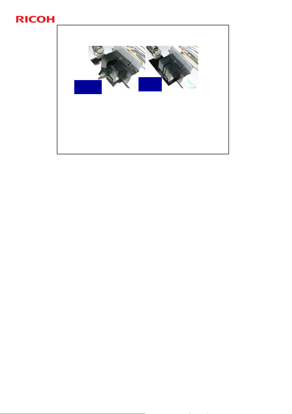
Ring Cartridge Detection
D392 Ring Binder Training
Actuator
Out
Cartridge Detection Sensor (S801): if the ring cartridge is
missing or is not installed correctly.
Slide 35
No additional notes
Actuator
In
When the ring cartridge is pushed in, the actuator is pushed
out of the sensor.
When the ring cartridge is pulled out, the actuator goes into
the sensor.
35
Page 36
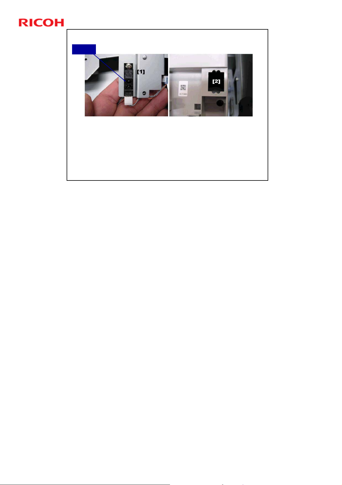
D392 Ring Binder Training
Sensor
Ring Type Detection
Ring Cartridge Type Sensor (S805): Detects which type of
ring cartridge is installed (A4 or LT).
The A4 cartridge has a cover. The LT cartridge does not.
The sensor checks if the cartridge has a cover or not.
Slide 36
The photo on the right shows a cartridge without a cover [2]. This is detected as
LT.
36
Page 37
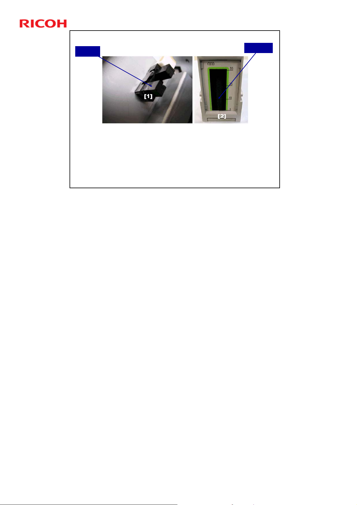
D392 Ring Binder Training
Sensor
Ring Near-End Sensor (S803): Detects when approximately 5
rings remain in the ring cartridge.
Slide 37
No additional notes
Ring Near-end Detection
There is a weight on top of the stack of rings. The sensor actuator
is attached to this weight.
The user can see how many rings remain, by looking through the
window. There is also a scale, which is attached during the
installation procedure.
Window
37
Page 38
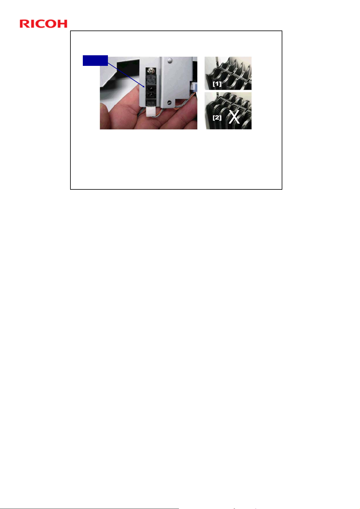
Detecting Incorrect Ring Installation
Sensor
Rings Reversed Sensor (S802): Detects when rings have
been loaded upside-down.
Rings must be loaded in the cartridge with the open side
facing up [1].
Slide 38
D392 Ring Binder Training
No additional notes
38
Page 39
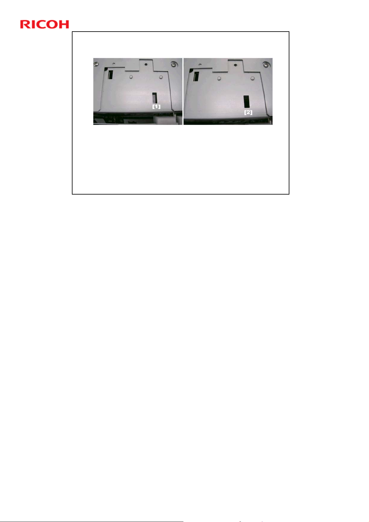
Detecting Incorrect Ring Installation
When the rings are loaded correctly, this pushes a cover
into the window [1].
When the rings are loaded incorrectly, the cover does not
appear on the window [2].
The sensor tries to detect the cover.
Slide 39
D392 Ring Binder Training
No additional notes
39
Page 40
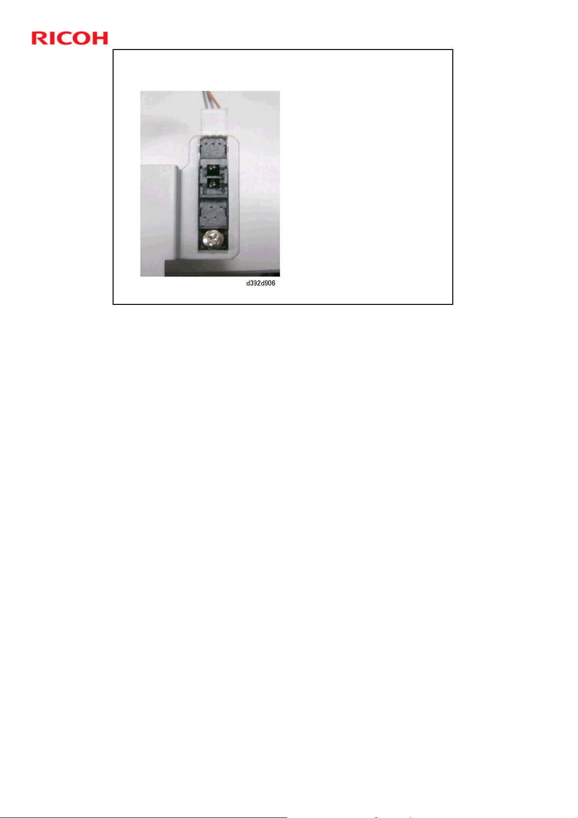
Slide 40
D392 Ring Binder Training
Ring Size Detection - 1
50/100 Ring Detection
Sensor (S804): Detects the
ring size.
There are only two ring
sizes: 50-sheet, or 100sheet.
No additional notes
40
Page 41
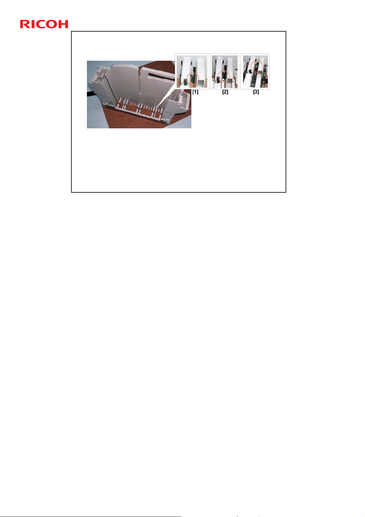
Ring Size Detection - 2
An actuator opens and closes a window on the right side of
the ring cartridge.
The actuator [1] remains up when 50-sheet rings [2] are
installed. The wider 100-sheet rings [3] push the actuator
down.
Slide 41
D392 Ring Binder Training
No additional notes
41
Page 42
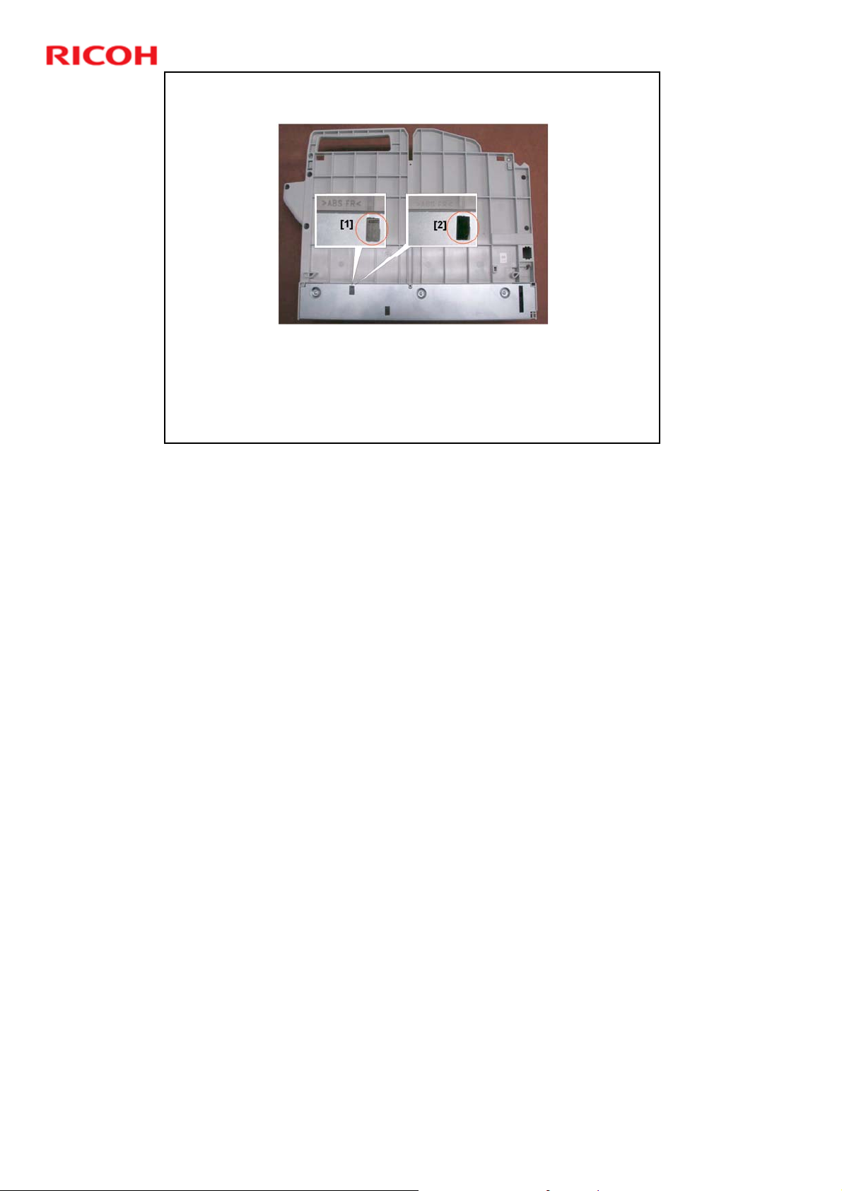
Ring Size Detection - 3
The cover on the right side of the cartridge remains closed [1]
when the 50-sheet size rings are installed.
The cover opens [2] when the 100-sheet size rings depress the
actuator.
The sensor detects if the cover is open (50-sheet rings) or closed
Slide 42
(100-sheet rings).
D392 Ring Binder Training
No additional notes
42
Page 43

Slide 43
D392 Ring Binder Training
Binder Unit
Pre-bind Jogger Unit
No additional notes
43
Page 44
Stack Tamper
Jogger
D392 Ring Binder Training
Pre-bind Jogger Unit
Paddle Roller
Clamp
Shutter
Stack
Thickness
Detection
Slide 44
Alignment
Pins
Stack
Runout
The functions of these units will be explained on the next few slides.
44
Page 45
Slide 45
Feed-in from the Punch Unit
M303 (Punch Unit Runout
Motor): Drives the punch
runout roller.
M601
M303
This feeds the punched
sheet out of the punch unit
to the pre-bind jogger.
M601 (Paddle Roller Motor):
Drives the paddle roller.
This pushes the leading
edge of each sheet against
the raised shutter to align
the stack.
The motor drives the roller
at a speed that is slightly
faster than the line speed.
D392 Ring Binder Training
No additional notes
45
Page 46
Slide 46
Stack Tamper
M607 (Stack Tamper
Motor): Drives a cam that
M607
S612
operates the tamper arms,
posts, and mylar sheet.
These press down the
This makes the path
S612 (Stack Tamper HP
Sensor): Detects the
actuator on the tamper
fence and stops the stack
tamper motor (M607).
The allowed arc of
D392 Ring Binder Training
trailing edge of each
sheet as it enters the
pre-bind jogger unit.
clear for the next sheet.
rotation is 90 degrees.
No additional notes
46
Page 47
D392 Ring Binder Training
Wheel, with
Posts
Tamper HP
Sensor
Stack tamper motor: Drives the wheels, through a cam. The
wheels push the posts and tamper arms down, which push the
mylar plate down onto the trailing edge of the paper.
HP sensor: Detects when to stop pushing the plate down.
Slide 47
No additional notes
Stack Tamper
Tamper Arms
Stack Tamper
Motor
Cam
Mylar Plate
47
Page 48
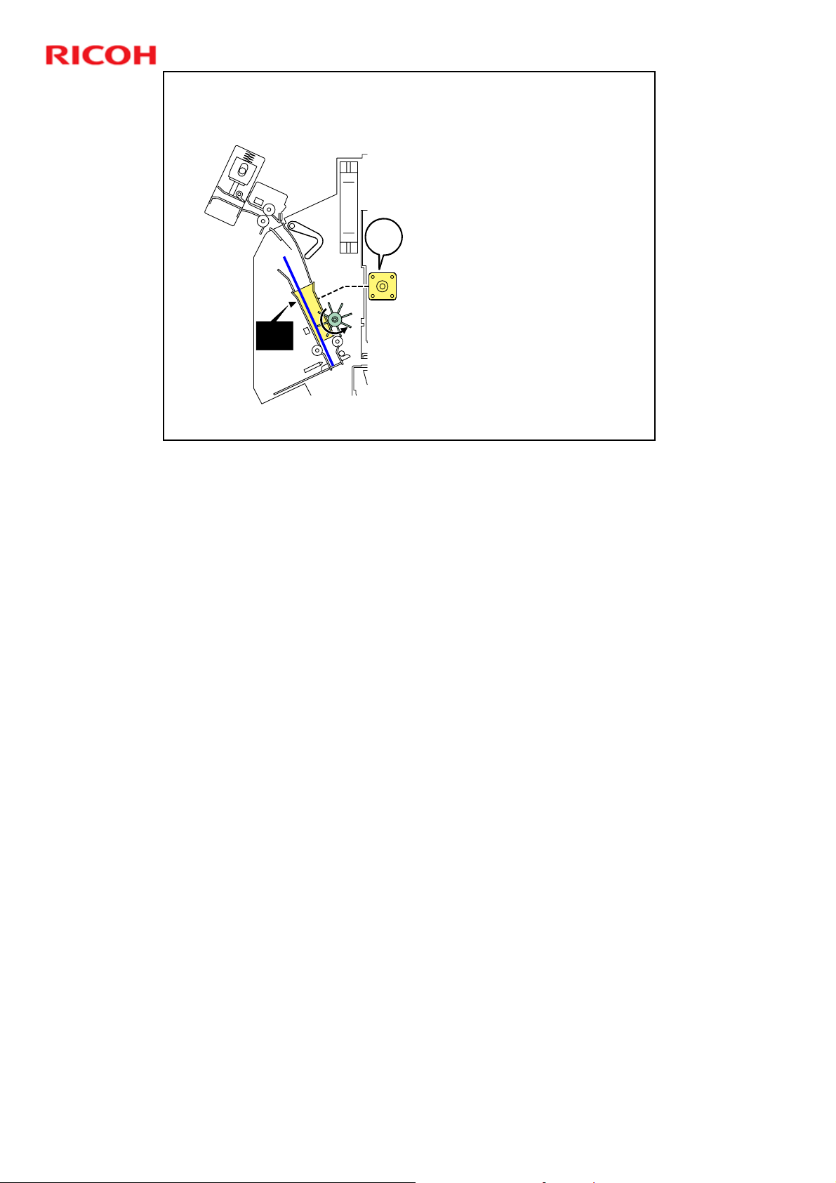
Slide 48
S601
S611
Pre-bind Jogger
Each fence has a motor
and a home position
sensor.
The front fence moves to
a set position for the
M604
M607
paper size.
The rear fence jogs the
paper against the front
fence.
D392 Ring Binder Training
No additional notes
48
Page 49
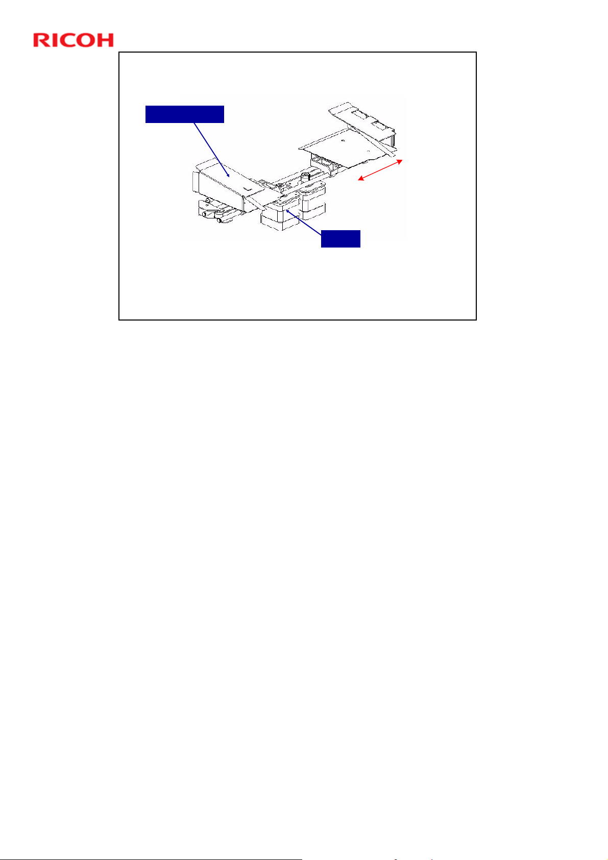
Jogger Fence
Slide 49
D392 Ring Binder Training
Pre-bind Jogger
Motor
No additional notes
49
Page 50
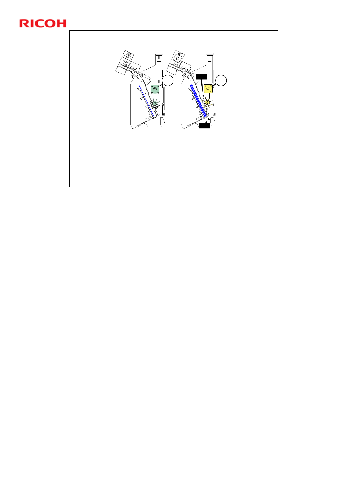
Paddle Roller
D392 Ring Binder Training
S602
M601 (Paddle Roller Motor): Drives the paddle roller.
M603 (Paddle Roller Lift Motor): Raises and lowers the paddle
roller to the proper height for the stack.
S602 (Paddle Roller HP Sensor): Detects the descending paddle
roller and switches off the paddle roller motor (M601) to stop the
roller at its home position.
Slide 50
M603M601
S612
S612 (Stack Tamper HP Sensor): Already described
50
Page 51
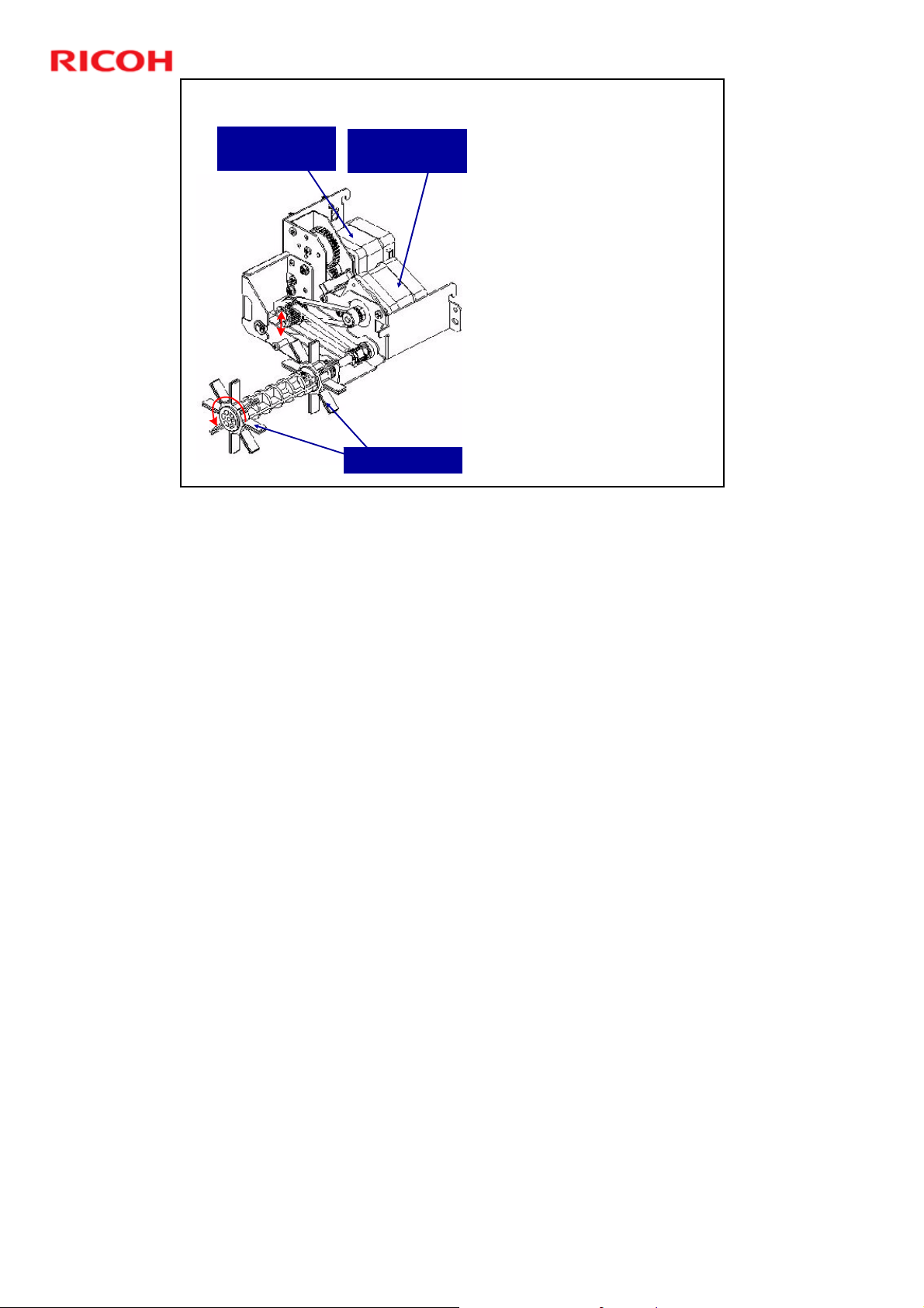
Paddle Roller
Lift Motor
Paddle Roller
Paddle Roller
Motor
Paddle rollers: Push the
leading edge of each sheet
against the raised shutter
to align the stack.
Paddle Roller Lift Motor:
Raises and lowers the
paddle roller to the proper
height for the stack.
D392 Ring Binder Training
At the end of the job, the
motor lowers the paddle
roller until home position
is detected by the paddle
roller HP sensor (S601).
Slide 51
Paddle Rollers
The paddle roller motor drives the roller at a speed that is slightly faster than the
line speed.
The readings of the stack thickness sensor (S607) determine how far the paddle
roller is raised by the lift motor. The stack thickness sensor is discussed later in
this section.
51
Page 52
D392 Ring Binder Training
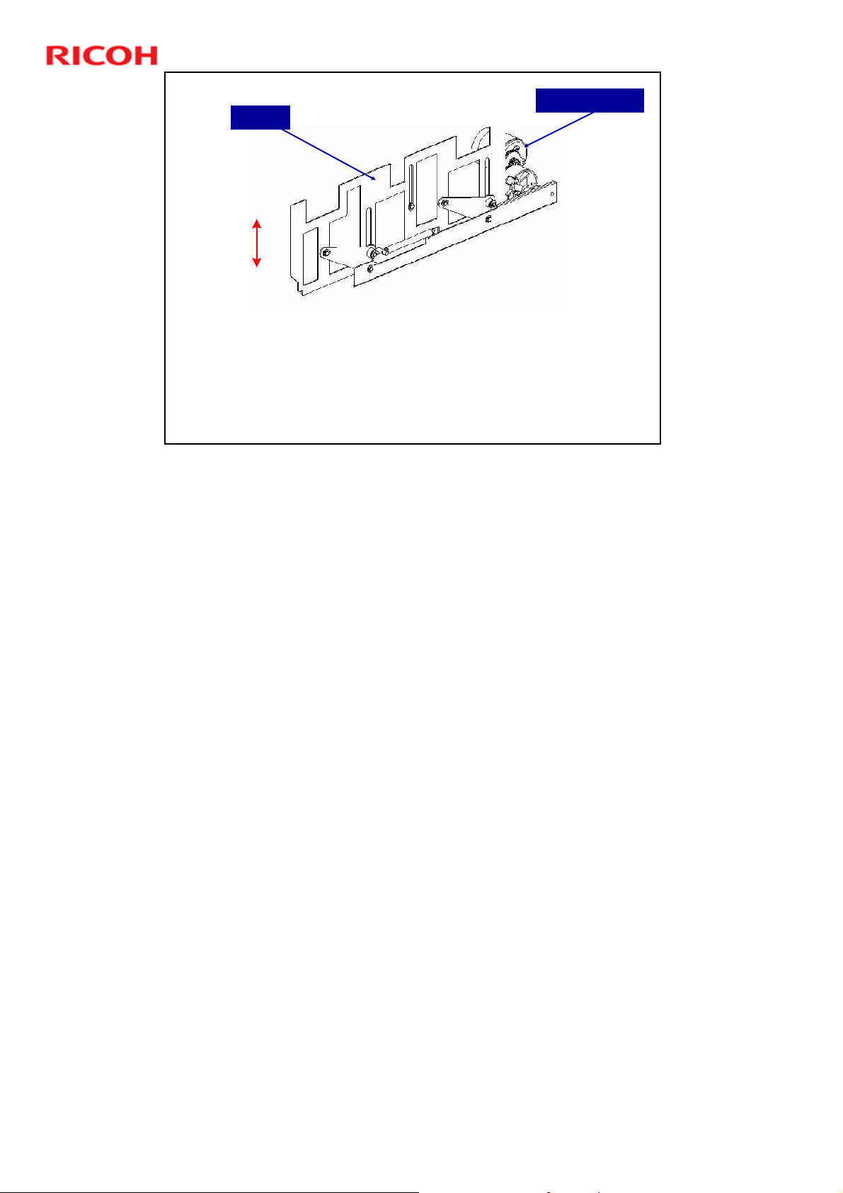
The shutter provides a fence to stop the leading edge of
each sheet as it enters the pre-bind jogger.
When the stack has been assembled, the shutter lowers so
that the stack can be fed to the next stage of the binding
process.
Slide 52
No additional notes
Shutter
Shutter
Shutter Motor
52
Page 53
Slide 53
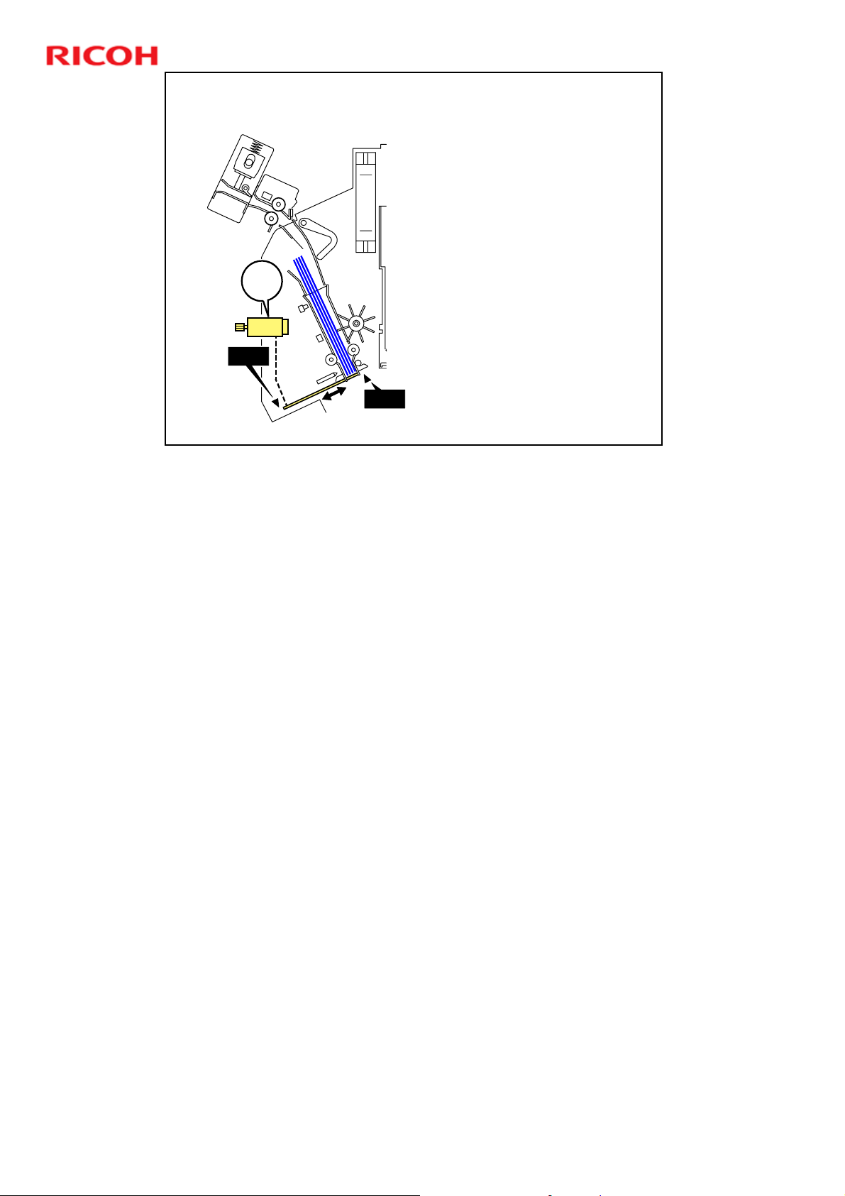
M608
S605
Shutter
M608 (Shutter Motor):
S613 (Shutter HP Sensor
S605 (Shutter HP Sensor
S613
D392 Ring Binder Training
Raises and lowers the
shutter.
2): Detects when the
shutter is fully raised so
that the leading edge of
the stack can be aligned
against the shutter.
1): Detects when the
shutter is fully lowered, so
that the stack can be fed
out to the next stage of
the binding process.
No additional notes
53
Page 54
Alignment Pins
Pins
Alignment
Pin Motor
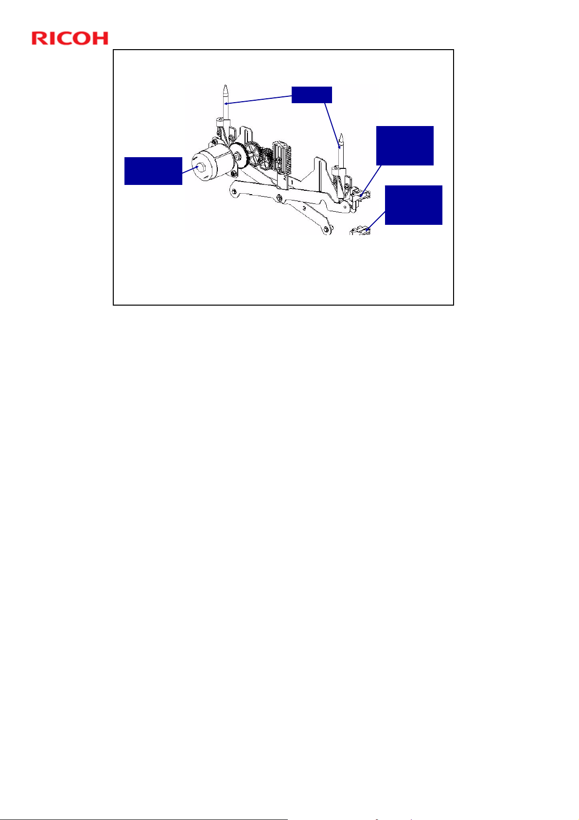
The two alignment pins are inserted into the holes at either end of
the punched edge to make sure that the spine is aligned correctly
so the rings can be inserted into the punched holes.
Normally, the pins are at their home positions detected by the
alignment pin HP sensor.
Slide 54
During the pin alignment, the pins project up untin detected by the
alignment pin up sensor.
D392 Ring Binder Training
Alignment
Pin Up
Sensor
Alignment
Pin HP
Sensor
The alignment pins are projected and retracted by a scissors lift (rack and pinion)
driven by the alignment pin motor.
This is the last alignment adjustment done before ring binding.
54
Page 55
Slide 55
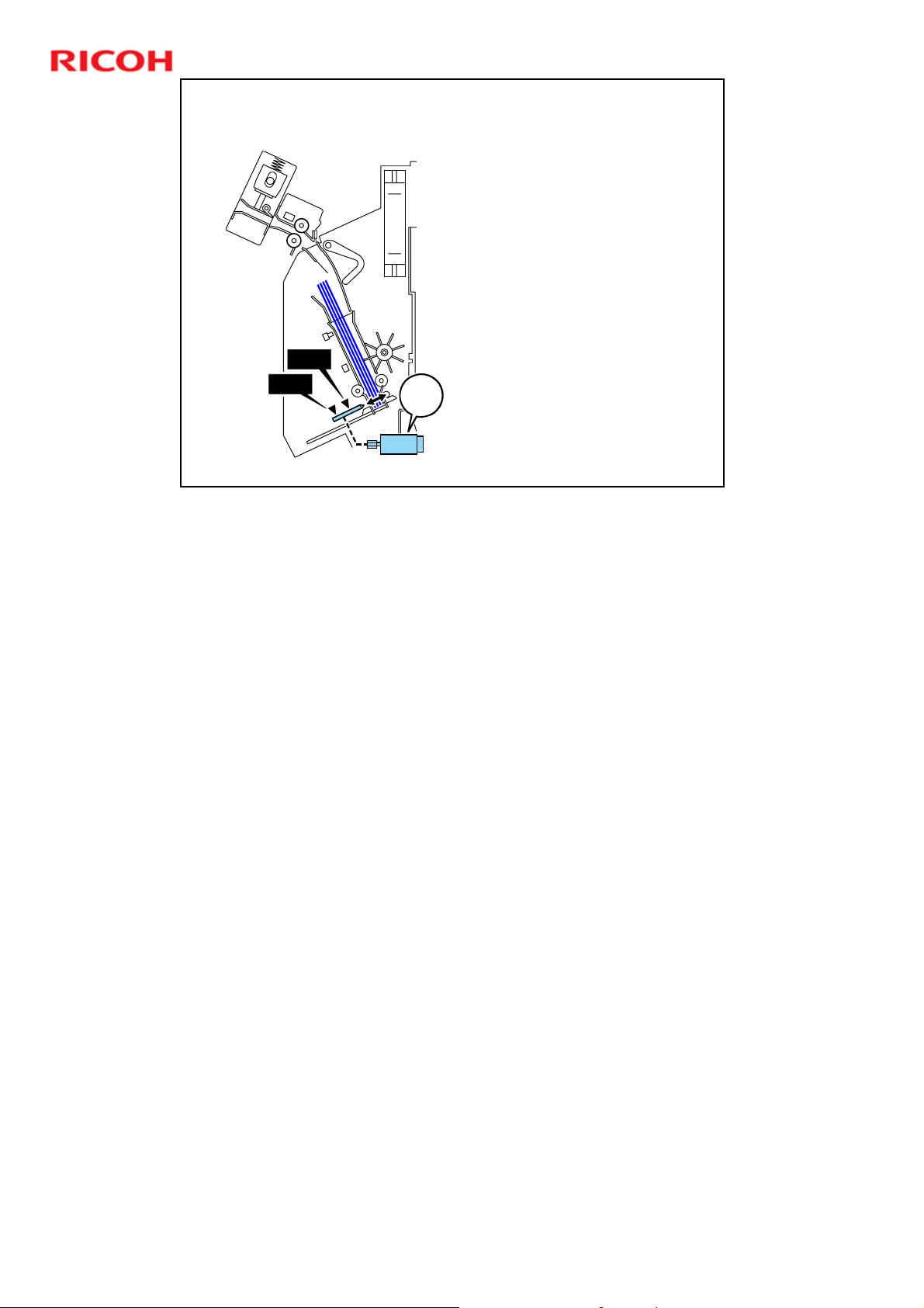
S610
S604
Alignment Pins
M602 (Alignment Pin
Motor): Raises and lowers
the alignment pins.
S610 (Alignment Pin Up
Sensor): Detects when the
alignment pins are at the
up position and inserted
into the two holes in each
end of the stack.
S604 (Alignment Pin HP
Sensor); Detects an
actuator on the alignment
pin linkage.
M602
This is the home
position, when the pins
have been moved away
from the stack.
D392 Ring Binder Training
No additional notes
55
Page 56
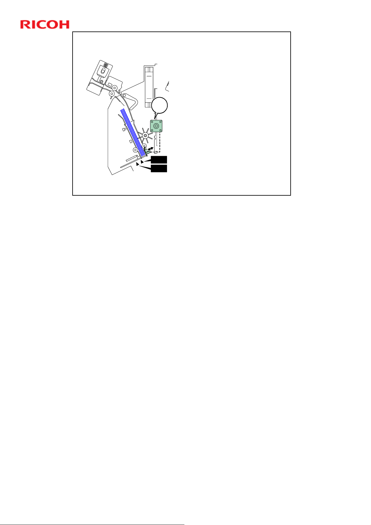
Slide 56
Detecting the Stack Thickness
S606 (50-Sheet Detection
Sensor): Detects when the
stack is thicker than 5.5 mm.
When binding a 50-sheet
document with the smaller
50-sheet rings, the job will
M605
S607 (Stack Thickness
S606
S607
stop if the sensor detects a
stack that is thicker than
5.5 mm.
Sensor): Measures the
thickness of the stack
through a cutout in the upper
arm plate.
This reading is used to
adjust the height of the
paddle roller when the
stack is jogged.
D392 Ring Binder Training
No additional notes
56
Page 57
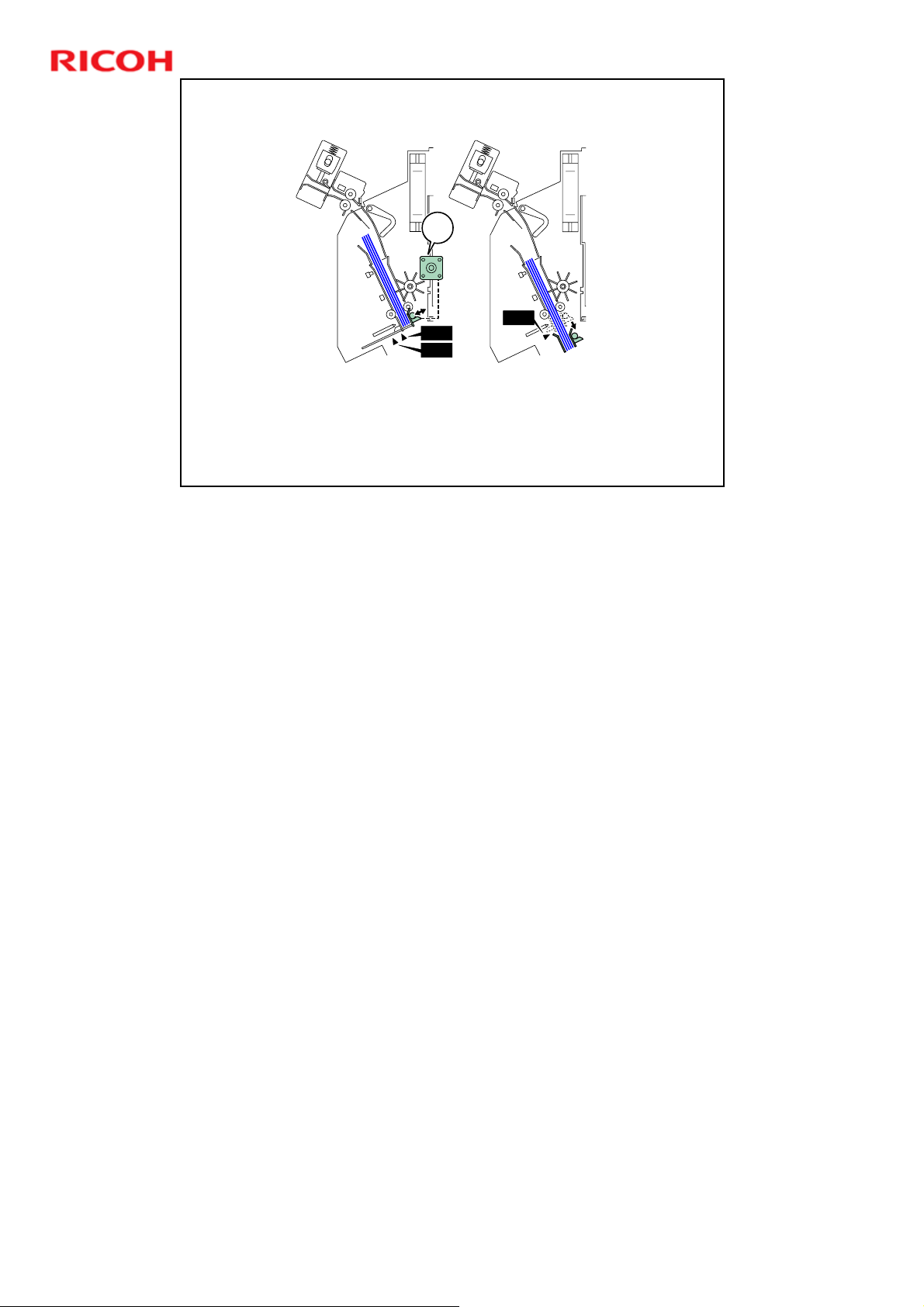
Clamping Before Binding
M605
D392 Ring Binder Training
M605 (Clamp Motor): Rotates the cam which opens and closes
the clamp that clinches the punched spine of the stack after it has
been jogged.
S603 (Clamp HP Sensor): Controls the operation of the clamp lift
Slide 57
cam that opens the arms of the clamp.
No additional notes
S606
S603
S607
The spine remains clamped until the rings have been inserted and
closed.
57
Page 58
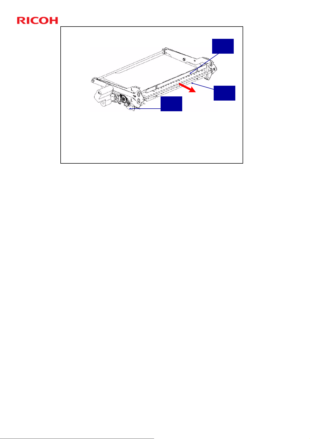
D392 Ring Binder Training
Clamping Before Binding
Clamp
Motor
The guide clamps hold the spine of the document before binding.
The clamp motor moves the upper clamp guide through a cam.
The rotation of the cam is controlled by the clamp HP sensor. The
clamp upper guide normally remains away from the bearing of the
clamp upper arm.
During ring binding, the stack is held only at the spine.
Slide 58
Upper
Clamp
Lower
Clamp
During clamping, the upper and lower clamps are held closed by large springs.
The clamp binder motor pulls the pre-bind jogger, with the clamped stack, into
the ring binder. We will see this in the next section.
58
Page 59

Slide 59
D392 Ring Binder Training
Binder Unit
Ring Binding
No additional notes
59
Page 60
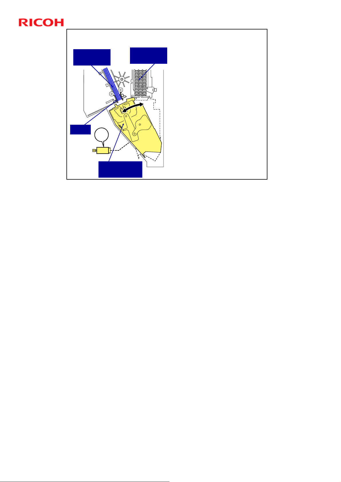
Pre-bind
Jogger Unit
Spine
Slide 60
Swinging the Ring Clamper Unit
Ring Supply
Unit
M701
Ring Clamper
Unit
The clamp binder motor
(M701) does the following:
Lifts the ring clamper to
the bottom of the ring
supply unit to take one
ring strip and pull it
away from the bottom of
the ring stack.
Swings the top of the
ring binder (holding the
ring strip) toward the
bottom of the pre-bind
jogger, where the
clamped spine of the
stack is exposed.
D392 Ring Binder Training
No additional notes
60
Page 61
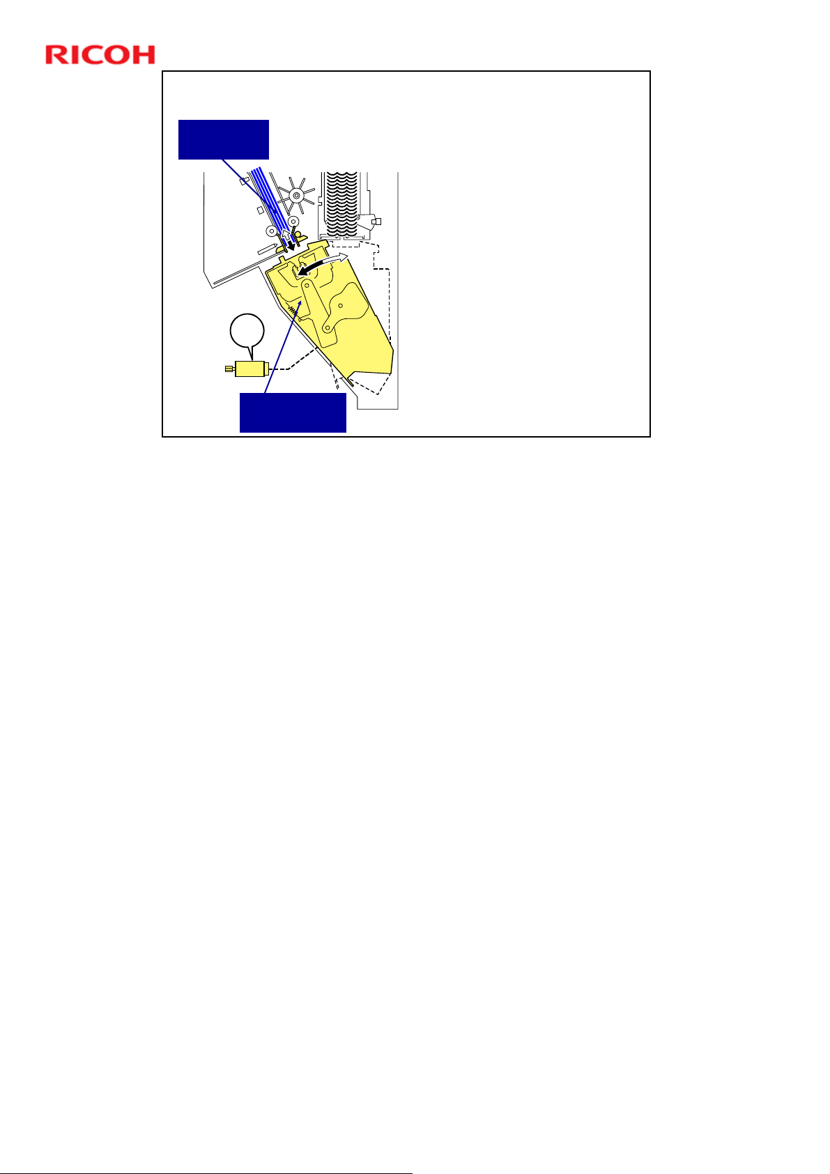
Positioning the Stack for Binding
Pre-bind
Jogger Unit
Slide 61
M701
Ring Clamper
Unit
The clamp binder motor
(M701) pulls the pre-bind
jogger into the ring
clamper unit.
This lowers the clamped
spine of the document in
time with the closing of
the rings through the
punched holes.
D392 Ring Binder Training
No additional notes
61
Page 62
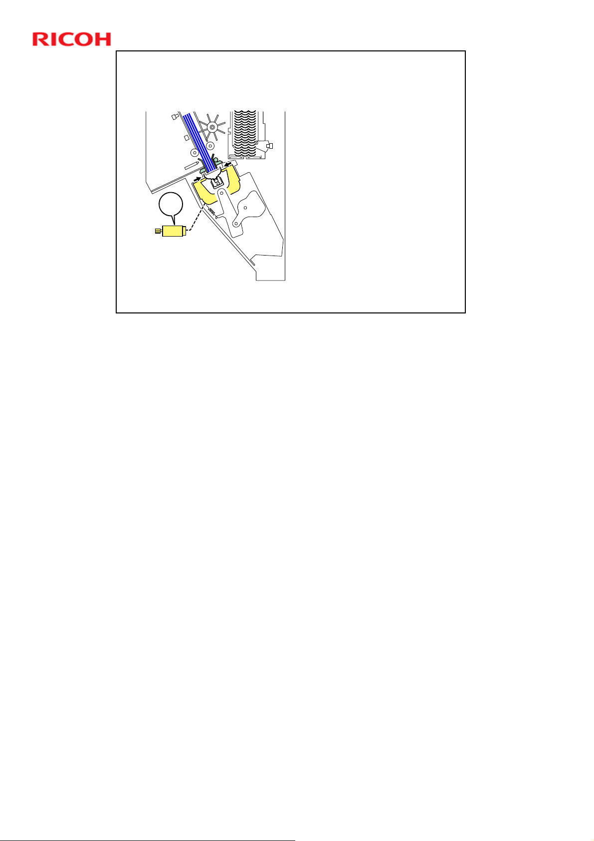
Slide 62
M701
D392 Ring Binder Training
Binding
The clamp binder motor
(M701) closes the rings
into the holes in the spine
of the document.
After inserting the rings,
the clamp binder motor
moves the ring binder unit
back to the vertical
position, to catch the next
ring from the ring
cartridge.
There is a complex mechanism of cams and linkages.
If possible, study this on a machine, while turning the shaft of the clamp binder
motor.
62
Page 63
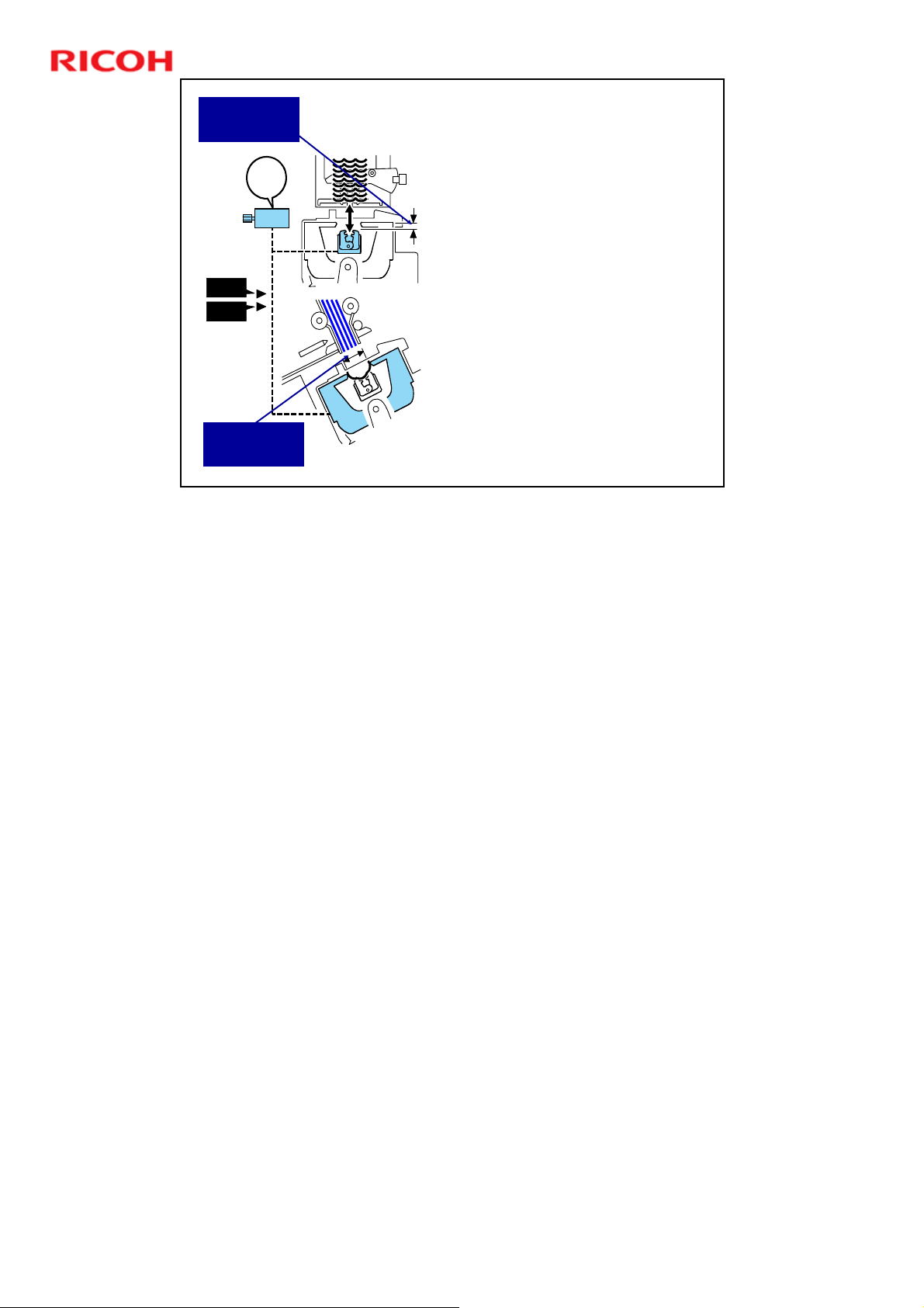
D392 Ring Binder Training
Depth
Adjustment
M702
S706
S707
Pitch
Adjustment
Slide 63
Switching the Ring Size
M702 (50/100 Clamp Adjust
Motor): Operates the two
switching cams that adjust
the pitch and depth for the
size of the rings so they will
be closed properly.
S707 (Ring Switch Timing
Sensor): Confirms that the
cam has reached the stop
position at the pitch setting
for the ring size.
S706 (Ring Switch HP
Sensor): Confirms that the
cams have returned to home
position after they have
adjusted the depth and pitch
for closing and locking the
rings.
The linkage depth and the binding pitch must be adjusted for the size of the ring
(50 or 100-sheet size).
The 50/100 clamp adjust motor (M702) drives a gear and switching cams 1 and
2 above the same shaft. Switching cam 1 switches the binding pitch and
switching cam 2 switches the linkage depth.
63
Page 64

Slide 64
D392 Ring Binder Training
Output and Stacking
No additional notes
64
Page 65
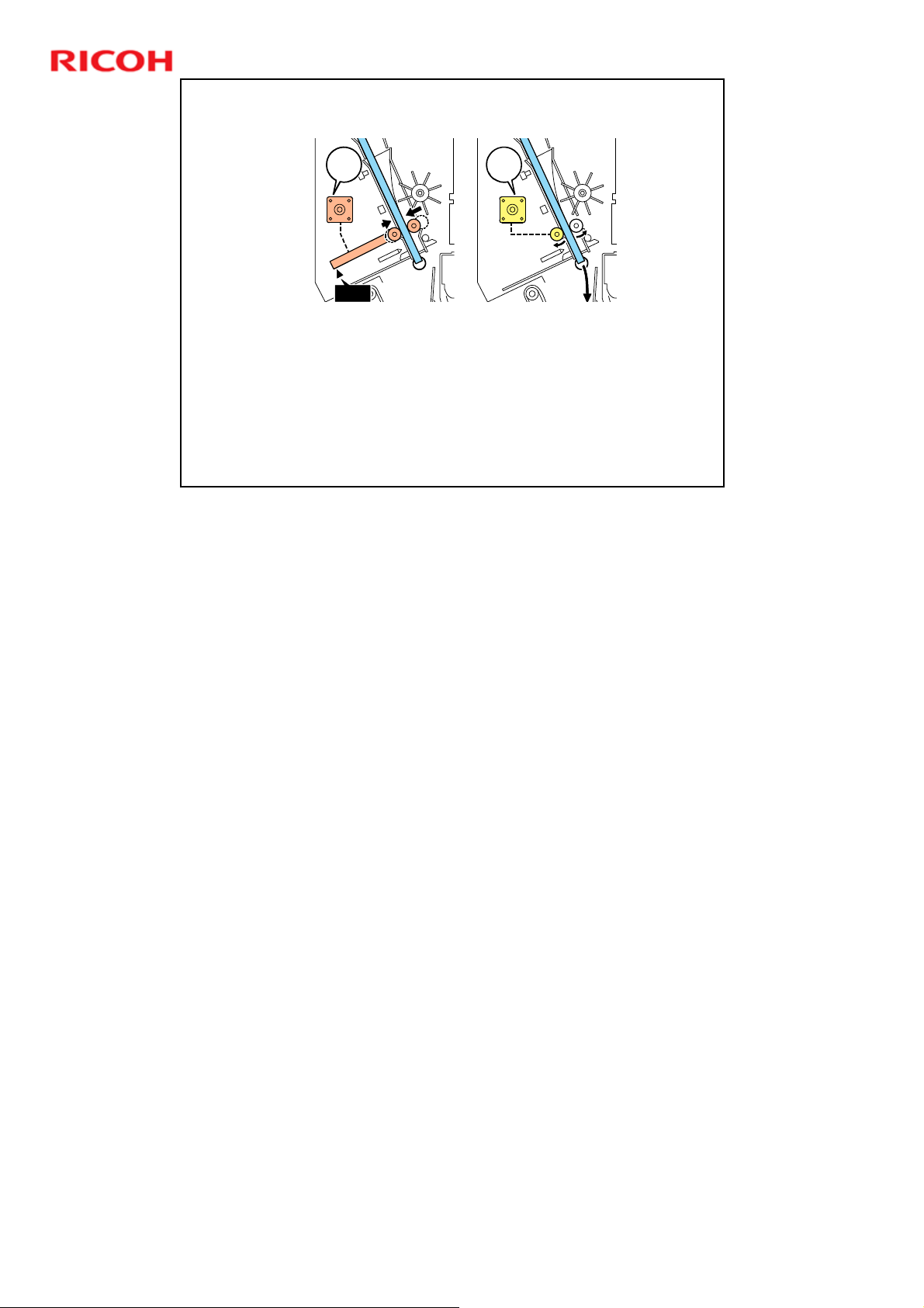
Output from the Binder Unit
D392 Ring Binder Training
M610 (Runout Press Roller Motor): Raises and lowers the press
roller to adjust it to the thickness of the book before the runout
roller motor turns on.
M609 (Runout Roller Motor): Rotates the runout press roller that
feeds the bound book out of the binder unit.
S614 (Runout Roller HP Sensor): Controls the runout press roller
motor (M610). The home position is up (nip released).
Slide 65
No additional notes
M610
S614
The roller must be moved to close the nip so that the bound stack
can be fed out of the binder unit.
M609
65
Page 66
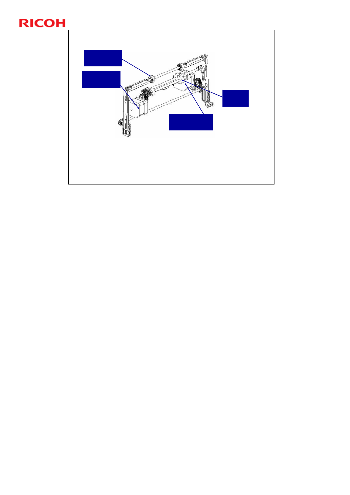
Output from the Binder Unit
Runout
Press Roller
Runout
Roller Motor
Runout Press
Roller Motor
After the runout press roller has been moved against the
stack, the runout roller feeds the stack out.
Slide 66
D392 Ring Binder Training
Runout
Roller
No additional notes
66
Page 67
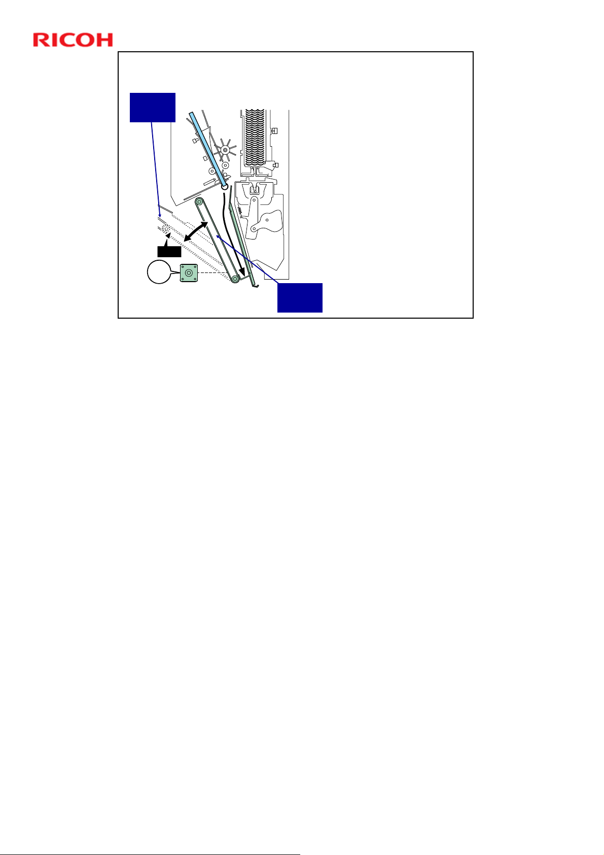
Catching the Stack with Output Belt 1
D392 Ring Binder Training
Output
Belt 2
S403
M403
Slide 67
No additional notes
M403 (Output Belt Rotation
Motor): Rotates the output
belt 1 assembly.
Rotates the assembly to
the vertical so that it can
receive the bound book
from the binder unit
Rotates the assembly back
to the left, to feed the book
to output belt 2.
S403 (Output Belt Rotation
HP Sensor): Detects when
the belt reaches the correct
position to feed the book on
to output belt 2, and stops
the output belt rotation motor
(M403).
Output
Belt 1
67
Page 68
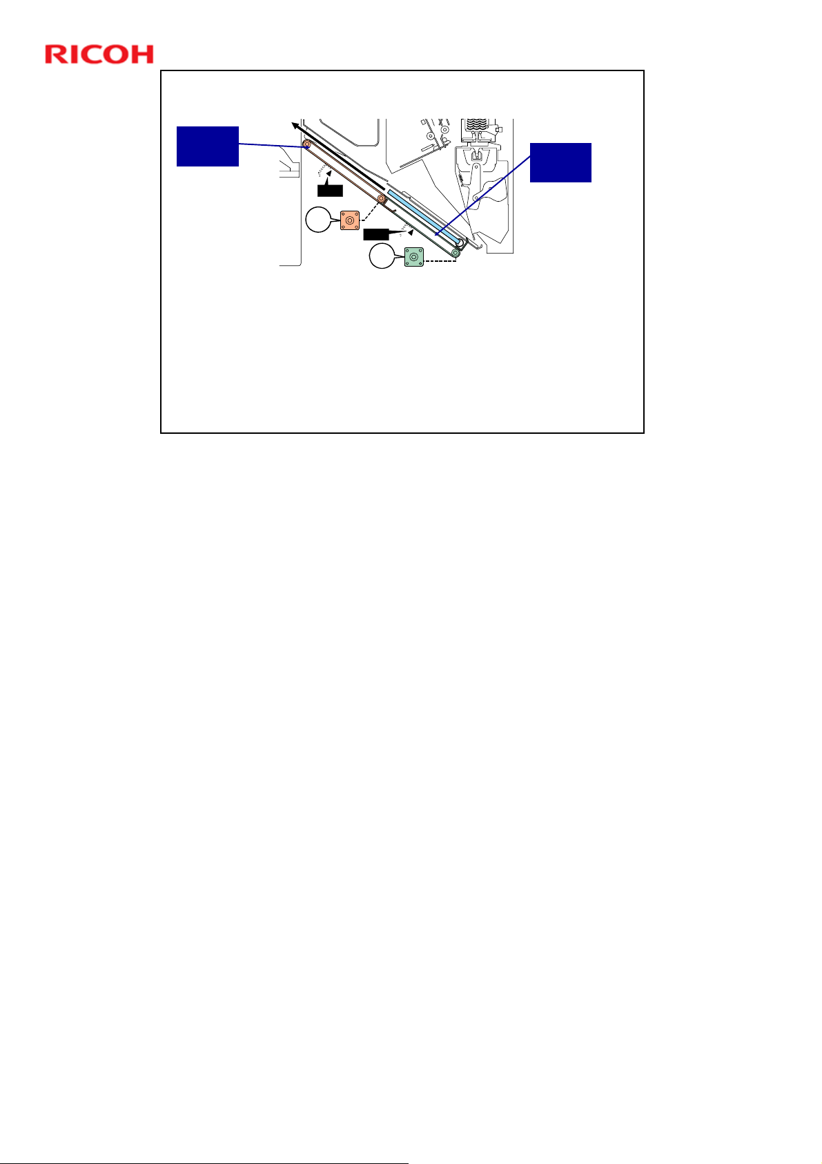
Feed-out with the Output Belts
Output
Belt 2
S402
M402
S401
M401
M401, M402 (Output Belt Motors): Drive output belts 1 and
2.
S401 (Output Belt 1 HP Sensor): Detects the home position
of the pawls mounted on output belt 1. The pawls push the
book onto output belt 2.
S402 (Output Belt 2 HP Sensor): Detects the home position
of the pawls mounted on output belt 2. The pawls push the
book onto the output stacking tray.
Slide 68
D392 Ring Binder Training
Output
Belt 1
HP sensors: With the pawls at their home positions, the belt is ready to move the
next book received from the binder unit (in the case of S401), or from output belt
1 (in the case of S402).
68
Page 69
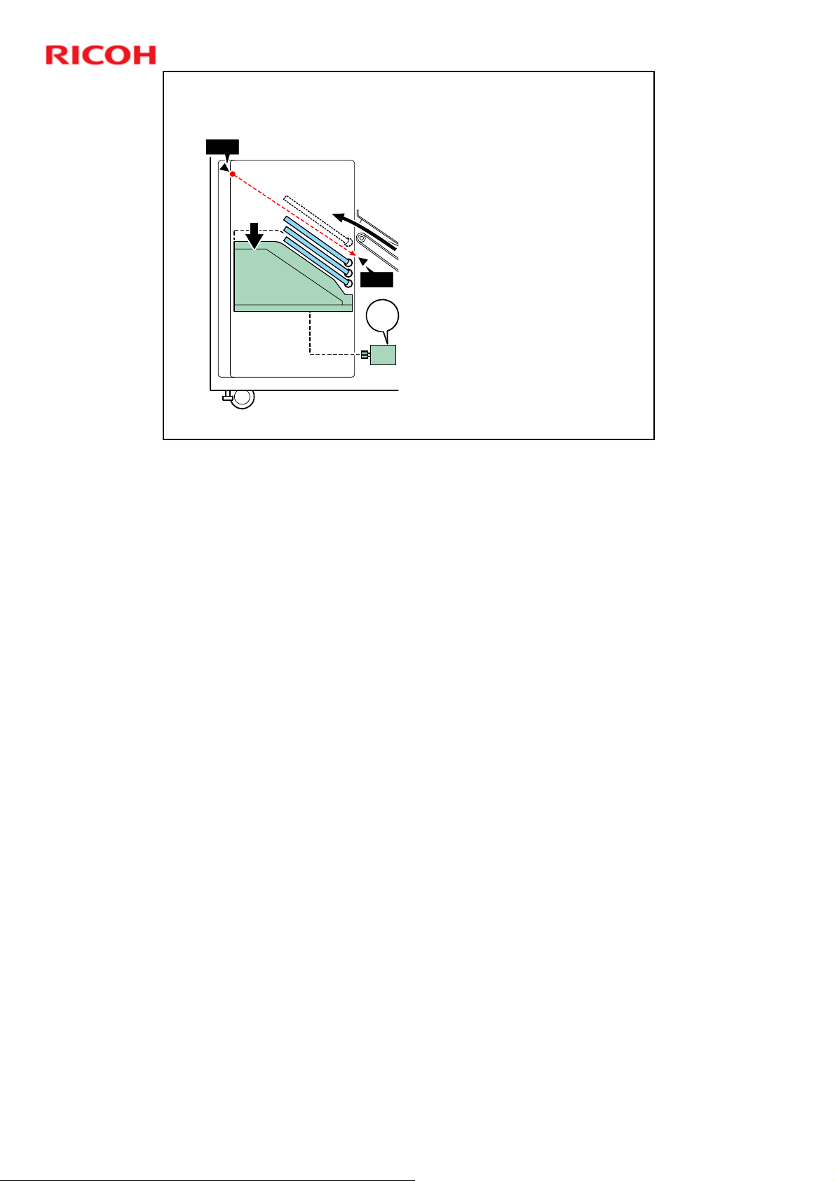
Stacking the Output - 1
D392 Ring Binder Training
S502
Slide 69
No additional notes
S502
M501
M501 (Stacker Motor):
Raises and lowers the
stacking tray, where the
bound books are output
from output belt 2.
S502 (Stack Height
Sensor): Detects the top
of the document stack on
the stacker tray and
signals when the stacker
tray is full.
69
Page 70
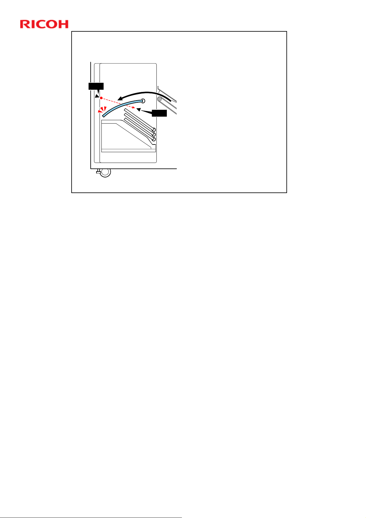
Slide 70
S507
D392 Ring Binder Training
Stacking the Output - 2
S507 (Book Position
Sensor): Checks the
position of the bound
book to detect book skew
or falling.
S507
No additional notes
70
Page 71
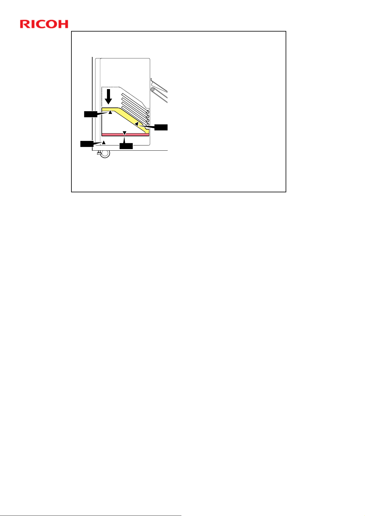
S501
Slide 71
S505
Stacking the Output - 3
S505 (Tray Detection Sensor):
Detects whether the stacker tray
is pulled out or pushed in.
S504 (Stacker Detection Sensor):
Detects a document on the
stacker tray at power on.
S501 (Stacker HP Sensor):
Detects the home position of the
stacker tray and stops the
stacker motor (M501).
S504
S506
The stacker tray is at its home
position when it is completely
down.
S506 (Obstacle Detection
Microswitch): The open space on
the left side of the finisher must
always remain open. If something
is placed under the tray, the tray
will trigger this switch and the
tray will stop.
D392 Ring Binder Training
No additional notes
71
Page 72

Slide 72
D392 Ring Binder Training
Replacement and Adjustment
The next few slides contain important points for replacement and adjustment.
72
Page 73
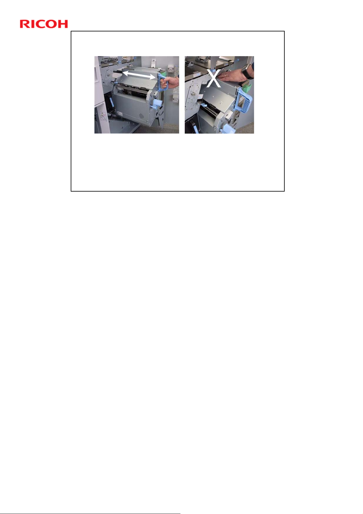
Pulling out/Pushing in the Binder Unit
Always grip handle Mc8 when pulling out or pushing in the binder
unit.
Never touch any other surface of the binder unit when it is
moving.
To avoid injury the fingers, never push on the top of the binder
unit to slide it back into the finisher.
Slide 73
D392 Ring Binder Training
No additional notes
73
Page 74
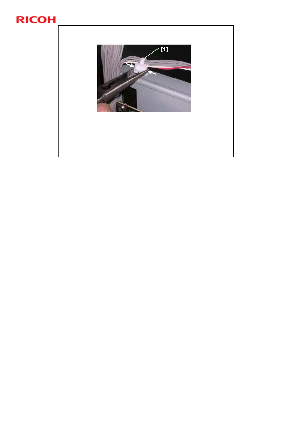
Standoffs on Harnesses - 1
Some harnesses are permanently locked by plastic bands
[1] to plastic standoffs that are attached to the frame.
Do not try to remove this band.
Use a pair of needle-nose pliers to press in the base of the
stand off and lift it out of its hole.
Slide 74
D392 Ring Binder Training
The base of a removed standoff can be quickly re-inserted into its hole.
74
Page 75

Standoffs on Harnesses - 2
If you must remove the band:
Press the end of the band loop.
Use a sharp tool to press down the lock band below (or above) the
looped band to separate the serrations of the bands and release
the loop.
This must be done for the two motors of the clamp unit, or the
band must be cut, which is not good.
Slide 75
D392 Ring Binder Training
No additional notes
75
Page 76
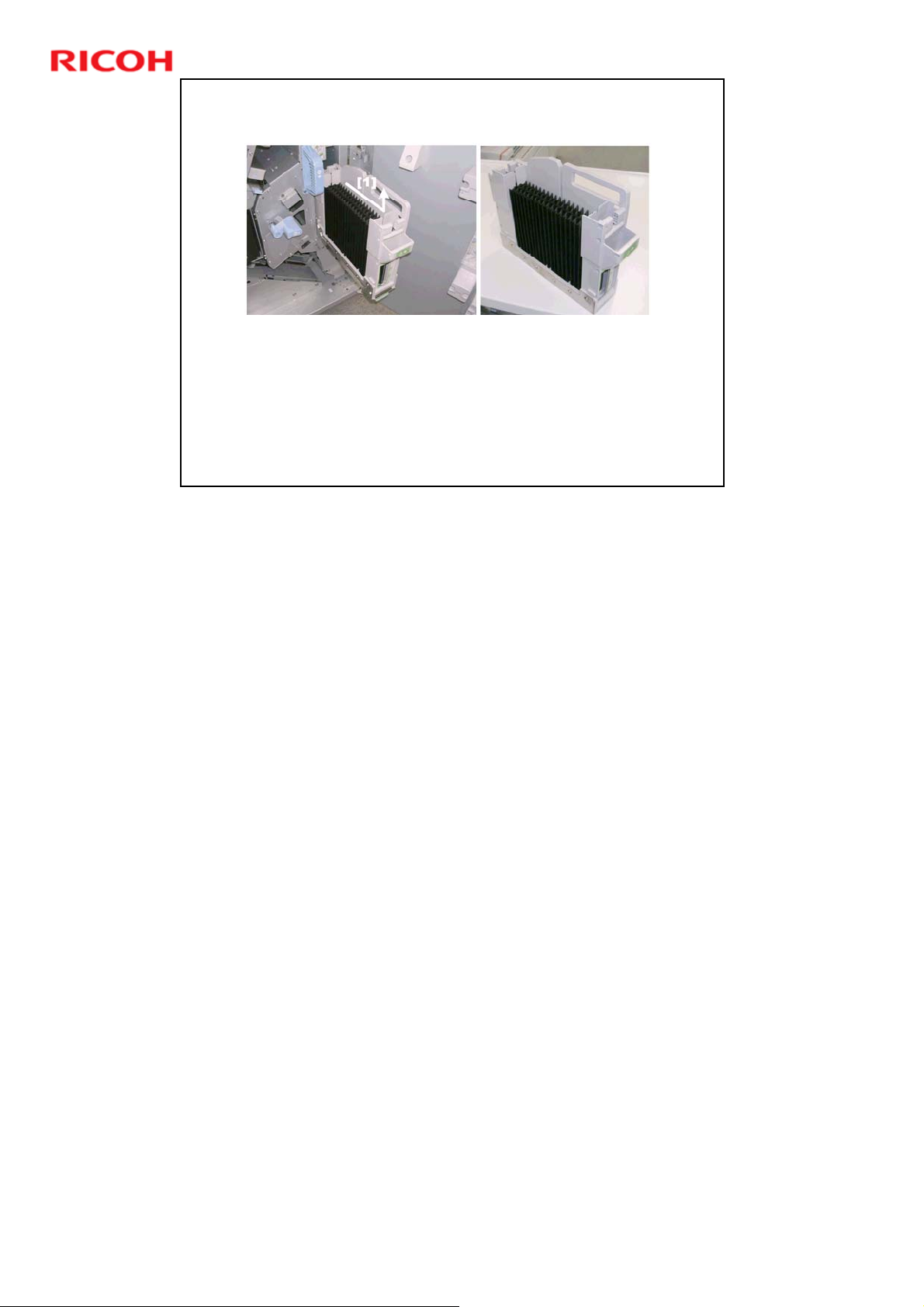
Ring Cartridge
Always remove the ring cartridge before removing the
binder unit for servicing.
Slide 76
D392 Ring Binder Training
No additional notes
76
Page 77
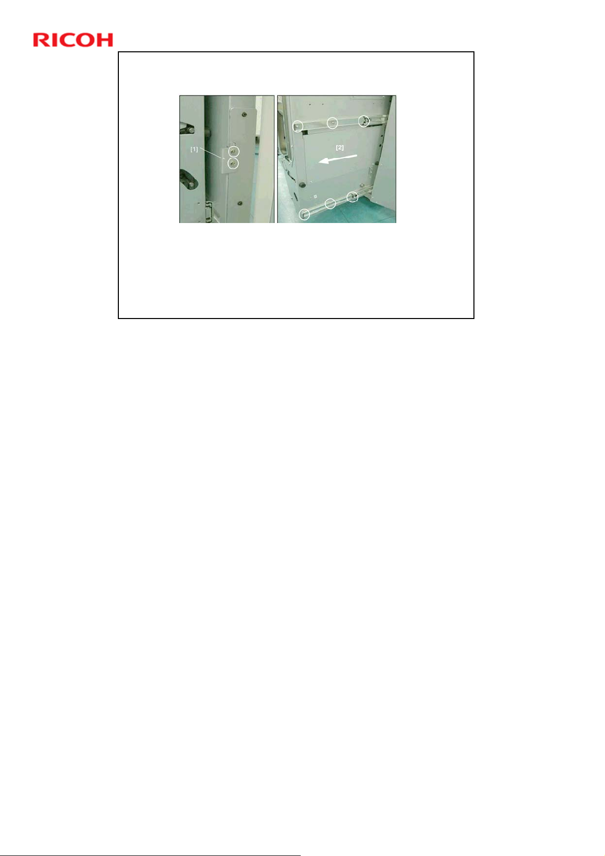
Working on the Binder Unit
It is recommended that the binder unit be removed for all
servicing and maintenance.
The binder unit wobbles on the rails and moves back into
the machine. So, it does not provide a stable platform for
removing sensors or motors.
Slide 77
D392 Ring Binder Training
No additional notes
77
Page 78
Slide 78
D392 Ring Binder Training
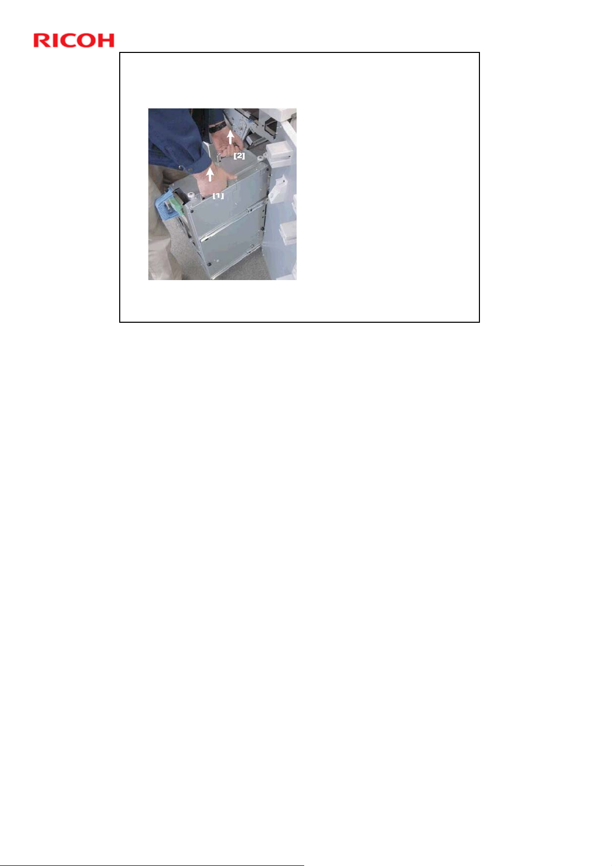
Lifting the Binder Unit - 1
Lift the binder unit by its
handles [1] and [2], pull it
straight up and then
slightly to the left to
disengage the right side
of the unit from the
machine.
The binder unit is heavy
and weighs about 22 kg
(50 lb).
No additional notes
78
Page 79
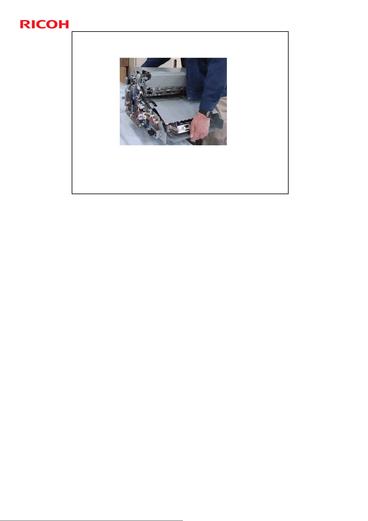
Lifting the Binder Unit - 2
Hold the binder unit from the rear with a firm grip under the
top and bottom of the unit.
Slide 79
D392 Ring Binder Training
No additional notes
79
Page 80
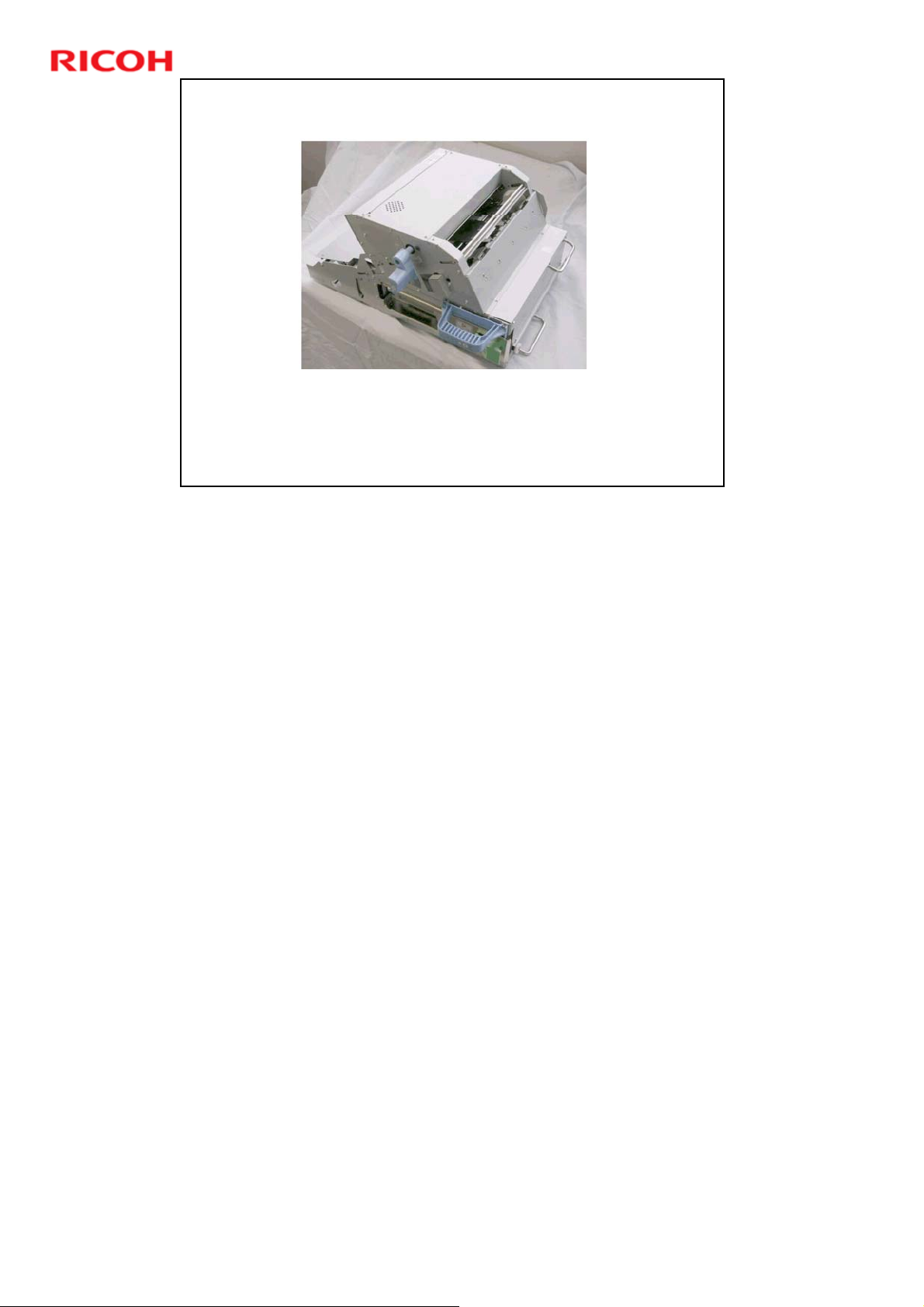
Lifting the Binder Unit - 3
Lay the binder on its right side with its rubber stoppers
down.
Slide 80
D392 Ring Binder Training
No additional notes
80
Page 81

SP6504
Adjust this SP after you replace one or more of the following
items:
Binder unit control board
Ring binder main board
Pre-punch jogger unit
Pre-punch jogger HP sensor (S301)
Multiply the value on the decal by "0.1". For example, if the value
is "-19" then input –1.9.
Do a run with the ring binder in the punch only mode (no ring
Slide 81
binding). Use paper in the weight range 70 to 90 g/m
2
D392 Ring Binder Training
.
SP6504-1 (A4 LEF) or SP6504-2 (LT LEF)
81
Page 82
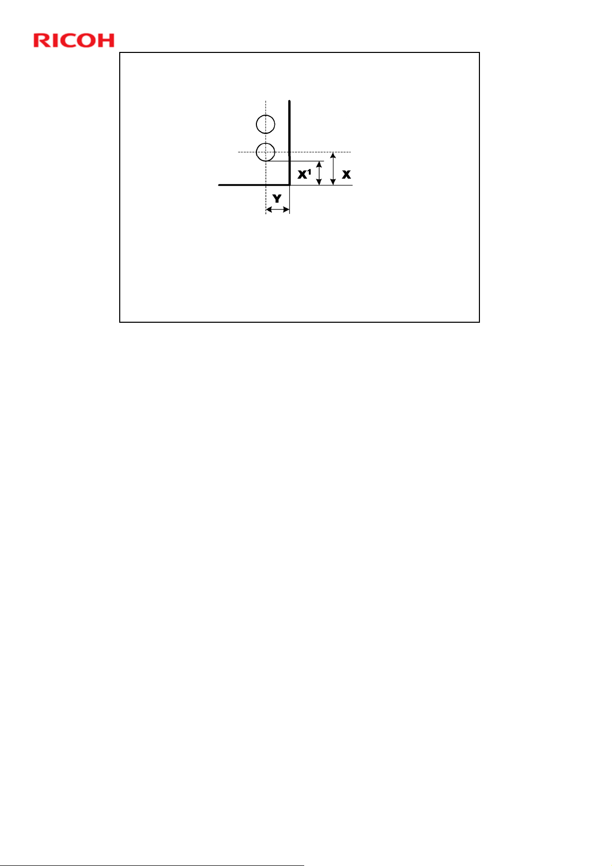
Adjusting SP6504 if the Hole
Position is Incorrect - 1
Check the position of the last punched hole.
Standard Values (mm)
X: 8.8 (A4), 12.7 (LT)
Y: 6 (A4), 6 (LT)
X1: 5.625 (A4), 9.52 (LT)
If Y is incorrect, replace the punch unit.
If X is incorrect, change the value of SP6504 as shown on the
Slide 82
following slide.
D392 Ring Binder Training
No additional notes
82
Page 83
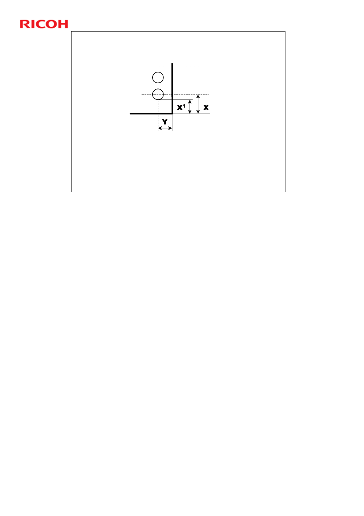
Adjusting SP6504 if the Hole
Position is Incorrect - 2
For example, if X1 is measured at "9.65“, this does not match the
standard for LT (X1 = 9.525). The hole is too high up the page.
Subtract the measured value (9.65) from the standard value
(9.525) and multiply it by "2".
9.525 - 9.65 = -0.125 x 2 = -0.250
Add "-0.250" to the setting of SP6504
Slide 83
D392 Ring Binder Training
The actual adjustment is done by adjusting the movement of the pre-punch
jogger fences so that the hole-punch position is lowered "-0.125".
The firmware does this automatically by dividing the entered value (-0.25) by 2 (-
0.125), so 9.65 – 0.125 = 9.525 mm.
In our example above, the measured distance is more than the standard value.
¾ If the measured distance is less than the standard value, then the
adjustment must raise the hole-punch position. The setting of SP6504 must
be made larger in order to raise the hole position.
83
Page 84
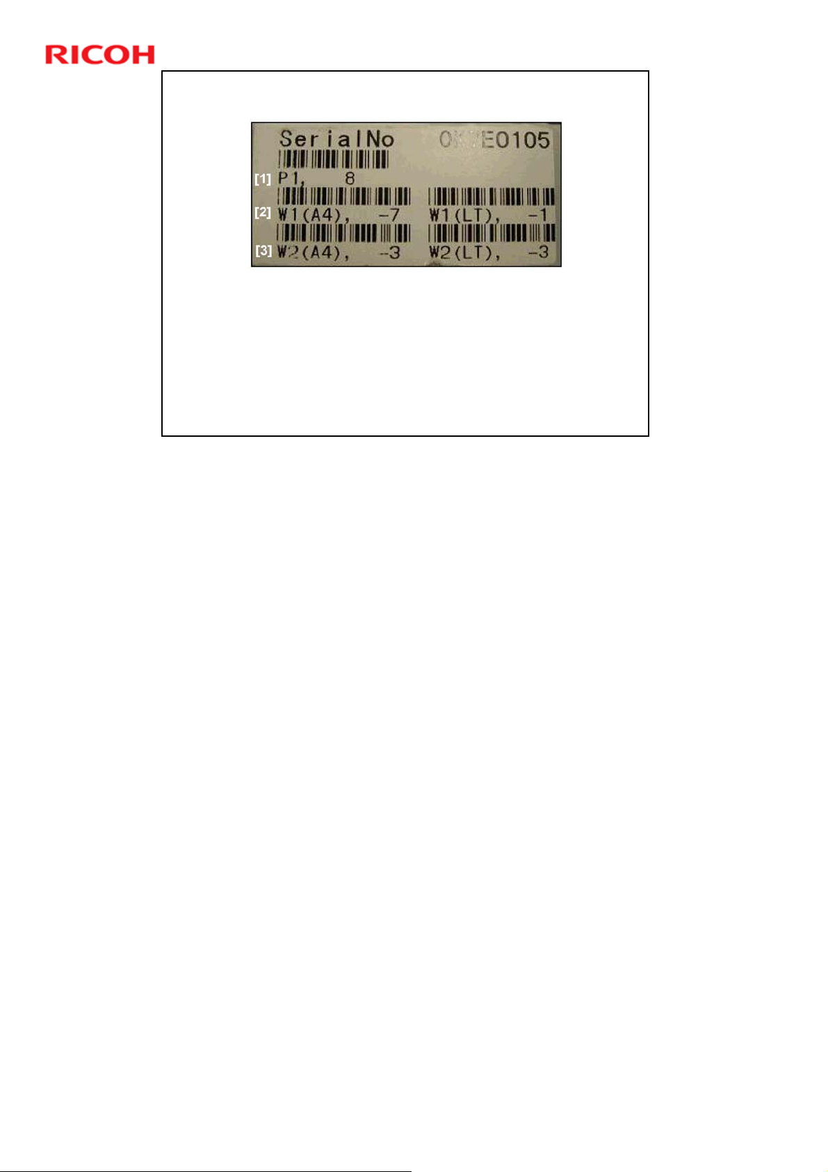
SP 6505, 6506, 6507
Adjust this SP after you replace one or more of the following
items:
Ring binder main board
Binder unit control board
Pre-bind jogger unit
Input the following values on the decal into the SPs:
[1]: SP6505
[2]: SP6506-1 (for A4), 6506-2 (for LT)
[3]: SP6507-1 (for A4), 6507-2 (for LT)
Slide 84
D392 Ring Binder Training
This label is attached to the front cover of the pre-bind jogger unit.
84
 Loading...