

Ricoh Capella-NB1e, G829 Service Manual

Capella-NB1e
(Machine Code: G829)
SERVICE MANUAL
4 June 2005
Subject to Change
IMPORTANT SAFETY NOTICES
1. Before disassembling or assembling parts of the network scanning box,
make sure that the network scanning box power cord is unplugged.
2. The wall outlet should be near the network scanning box and easily
accessible.
3. The output voltage of the PSU (Power Supply Unit) can be either 100 ~ 240
Vac, without any adjustment. Make sure that the above voltage is used.
4. The power cord should be an approved type, in accordance with the
regulations for the country in which the network scanning box is used.
5. When keeping used lithium batteries in order to dispose of them later, do not
put more than 100 batteries per sealed box. Storing larger numbers or not
sealing them apart may lead to chemical reactions and heat buildup.
Lithium Batteries (Memory Back-up)
CAUTION
The danger of explosion exists if a battery of this type is incorrectly
replaced.
Replace only with the same or an equivalent type recommended by the
manufacturer. Discard used batteries in accordance with the
manufacturer’s instructions.
Maintenance Information
The operating instructions explains how to use and maintain the network scanning
Box . Before performing the maintenance, read the operating instructions.
Warning concerning copyright
Many documents are copyrighted. Such documents may not be reproduced by
scanning or in any other form without the express permission of the copyright
holder.
Notice
The contents of this manual are subject to change without notice.
This manual uses several symbols.

Symbol What it means
Refer to section number
See Core Tech Manual for details
Screw
Connector
E-ring
Clip ring

i
TABLE OF CONTENTS
1. REPLACEMENT AND ADJUSTMENT ............................................1
1.1 SPECIAL TOOLS .........................................................................................1
1.2 REPLACEMENT........................................................................................... 1
1.2.1 REPLACING THE MCBU BOARD (MAIN CONTROLLER BOARD) ... 1
1.2.2 REMOVING THE OPERATION PANEL BOARD,
KEY TOP, LCD BOARD AND LED CONTROL BOARD ......................3
2. TROUBLESHOOTING .......................................................................
2.1 SC CODES................................................................................................... 7
3. SERVICE TABLES...........................................................................8
3.1 DIP SWITCH FUNCTION............................................................................. 8
3.2 SERVICE PROGRAM MODE....................................................................... 8
3.2.1 SP MODE DESCRIPTION................................................................... 8
Entering the service mode ....................................................................... 8
3.2.2 FIRMWARE UPDATE........................................................................ 11
Network firmware update ....................................................................... 11
3.2.3 BACKUP AND RESTORE SD CARD ................................................11
Backup SD card procedure.................................................................... 11
Restore SD card procedure ................................................................... 12
SPECIFICATIONS...............................................................................13
14 June, 2005 REPLACEMENT AND ADJUSTMENT
1
Spec.
1. REPLACEMENT AND ADJUSTMENT
CAUTION
Turn off the main power switch and disconnect the machine’s power cord
before you do the procedures in this section.
1.1 SPECIAL TOOLS
No special tool required for this model
1.2 REPLACEMENT
1.2.1 REPLACING THE MCBU BOARD (MAIN CONTROLLER
BOARD)
1. Remove the three screws from the lower cover.
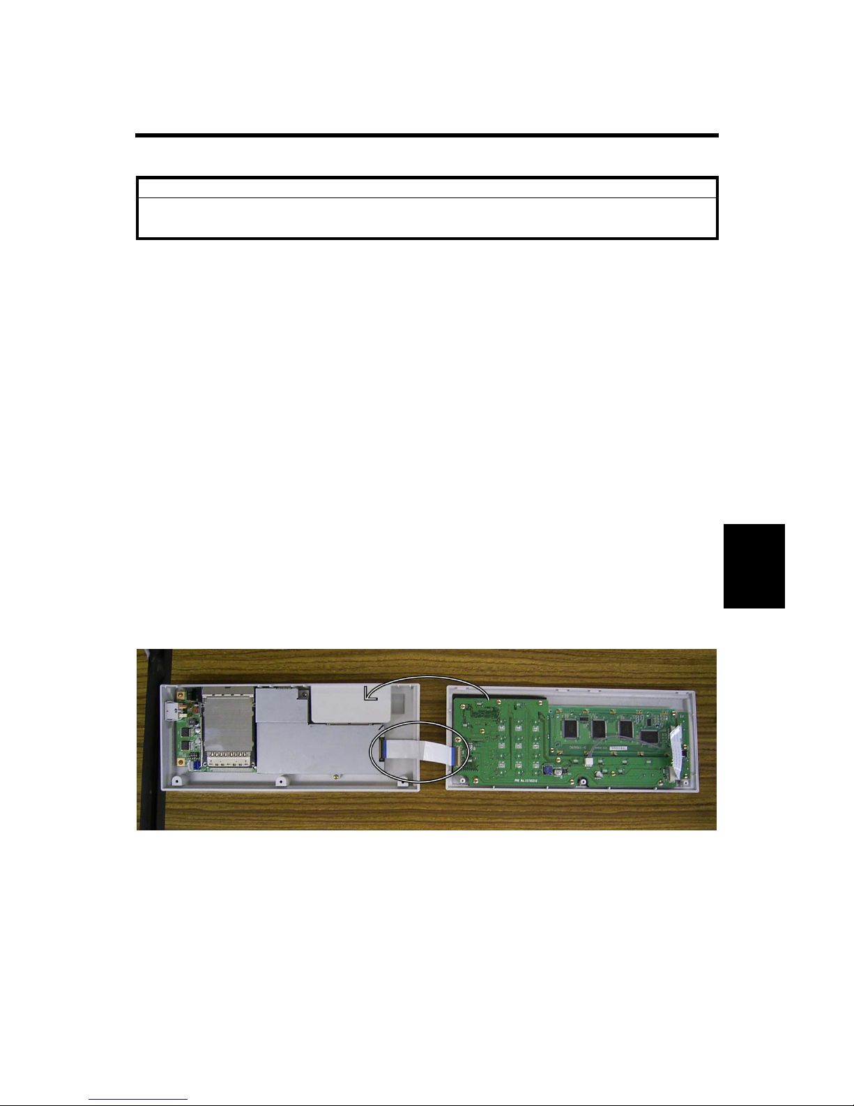
2. Pull down the lower cover and detach it from the four hooks.
3. Open the upper and lower covers, as shown in the photograph below.
Important: Be careful not to damage the flat cable.
4. Disconnect the flat cable from the MCBU board connector.
Note: In the photograph below, the MCBU board is on the left side.
REPLACEMENT AND ADJUSTMENT 14 June, 2005
2
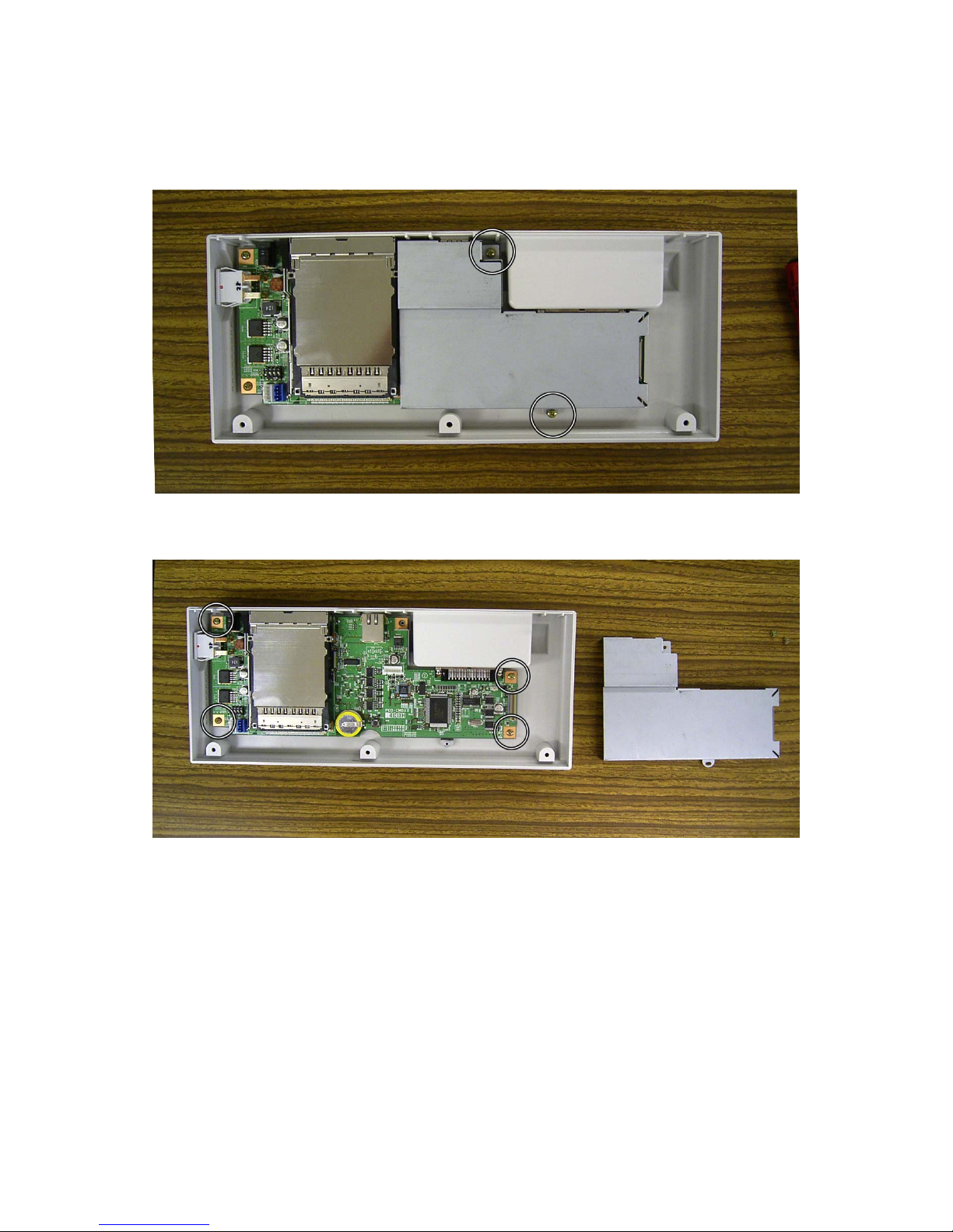
5. Remove the bracket ( x 2).
6. Remove the MCBU board ( x 4).
 Loading...