

Page 1

Setup Guide
Read This First
Trademarks.............................................................................................................3
Safety Information .................................................................................................4
Positions of RWARNING and RCAUTION labels ..............................................9
ENERGY STAR Program .....................................................................................10
Manuals for This Printer......................................................................................11
How to Read This Manual ...................................................................................12
Guide to the Printer
Exterior: Front View.............................................................................................13
Exterior: Rear View ..............................................................................................16
Inside.....................................................................................................................19
Control Panel........................................................................................................20
Setting Up
Where to Put the Printer......................................................................................22
Checking the Contents of the Box ..................................................................... 25
Unpacking.............................................................................................................28
Installing the Toner Cartridge.............................................................................36
Loading Paper......................................................................................................40
Turning the Power On .........................................................................................42
Selecting the Display Language.........................................................................44
Test Printing .........................................................................................................46
G1307525_1.00 EN USA G130-7503 Copyright © 2005 1
Page 2

Installing Options
Available Options.................................................................................................48
Option List ................................................................................................................48
Option Installation Flow Chart ..................................................................................49
Installing Options......................................................................................................50
Using the Screwdriver.........................................................................................54
Installing the Paper Feed Unit ............................................................................55
Installing Paper Feed Unit Type 7300 (500 × 1) ......................................................55
Installing Paper Feed Unit Type 7300 (500 × 2) ......................................................60
Installing Paper Bank Type 7300 (2000-sheet Large Capacity Tray) ...................... 65
Attaching Memory Unit Type C (SDRAM Module) ............................................71
Attaching User Account Enhance Unit Type E ................................................. 75
Attaching Printer Hard Disk Type 7100..............................................................79
Attaching Gigabit Ethernet Type 7300 ...............................................................84
Attaching IEEE 802.11b Interface Unit Type H ..................................................87
Attaching Bluetooth Interface Unit Type 3245 ..................................................91
Attaching IEEE 1394 Interface Board Type B....................................................94
Attaching IEEE 1284 Interface Board Type A....................................................97
Attaching Camera direct print card Type 7300 .................................................99
Attaching USB Host Interface Unit Type 7300.......................................................101
Installing Duplex Unit Type 7100......................................................................104
Installing the Duplex Reversal Unit Stand..............................................................104
Installing the Duplex Reversal Unit ........................................................................108
Installing the Duplex Feed Unit ..............................................................................112
Connecting the Printer
Network Connection ..........................................................................................115
USB Connection.................................................................................................118
Connecting a digital camera...................................................................................119
Parallel Connection ...........................................................................................121
IEEE 1394 Connection .......................................................................................122
Configuration
Ethernet Configuration......................................................................................123
IEEE 802.11b (Wireless LAN) Configuration ...................................................128
IEEE 1394 Configuration ...................................................................................134
IP over 1394...........................................................................................................134
SCSI print...............................................................................................................136
Installing the Printer Driver
Quick Install........................................................................................................138
Install the Operating Instructions.....................................................................140
2
Page 3

Read This First
Trademarks
Microsoft, Windows and Windows NT are registered trademarks of Microsoft
Corporation in the United States and/or other countries.
IPS-PRINT Printer Language Emulation Copyright© 1999-2000 Oak Technology, Inc., All rights reserved.
Bluetooth
Other product names used herein are for identification purposes only and might
be trademarks of their respective companies. We disclaim any and all rights to
those marks.
The proper names of the Windows operating systems are as follows:
•Microsoft
•Microsoft
•Microsoft
• The product names of Windows
Microsoft
Microsoft
Microsoft
• The product names of Windows
Microsoft
Microsoft
• The product names of Windows Server
Microsoft
Microsoft
Microsoft
• The product names of Windows NT
Microsoft
Microsoft
®
is a registered trademark of the Bluetooth SIG, Inc. worldwide.
®
Windows® 95 operating system
®
Windows® 98 operating system
®
Windows® Millennium Edition (Windows Me)
®
®
Windows® 2000 Advanced Server
®
Windows® 2000 Server
®
Windows® 2000 Professional
®
Windows® XP Professional
®
Windows® XP Home Edition
®
Windows ServerTM 2003 Standard Edition
®
Windows ServerTM 2003 Enterprise Edition
®
Windows ServerTM 2003 Web Edition
®
Windows NT® Server 4.0
®
Windows NT® Workstation 4.0
2000 are as follows:
®
XP are as follows:
TM
2003 are as follows:
®
4.0 are as follows:
G1307525_1.00 Copyright © 2005 3
Page 4
Read This First
Safety Information
When using your printer, the following safety precautions should always be followed.
In this manual, the following important symbols are used:
Indicates a potentially hazardous situation which, if instructions are not followed, could result in
death or serious injury.
Indicates a potentially hazardous situation which, if instructions are not followed, may result in
minor or moderate injury or damage to property.
4
Page 5

Read This First
• Only connected the machine to the power source described on the inside front cover of this manual.
• Avoid multi-wiring.
• Do not damage, break or make any modifications to the power cord.
Do not place heavy objects on it, pull it hard or bend it more than necessary. These actions could cause an electric shock or fire.
• Do not plug or unplug the power cord with your hands wet. Otherwise,
an electric shock might occur.
• Make sure the wall outlet is near the machine and freely accessible so
that in event of an emergency it can be unplugged easily.
• Do not remove any covers or screws other than those specified in this
manual. Some parts of the machine are at a high voltage and could
give you an electric shock. Also, if the machine has laser systems, direct (or indirect) reflected eye contact with the laser beam may cause
serious eye damage. When the machine needs to be checked, adjusted, or repaired, contact your service representative.
• Do not take apart or attempt any modifications to this machine. There
is a risk of fire, electric shock, explosion or loss of sight. If the machine has laser system, there is a risk of serious eye damage.
• If the machine looks damaged or breaks down, smoke is coming out,
there is a strange smell or anything looks unusual, immediately turn
off the operation and main power switches then unplug the power
cord from the wall. Do not continue using the machine in this condition. Contact your service representative.
• If metal, liquid or foreign matter falls into the machine, turn off the operation and main power switches, and unplug the main power cord.
Contact your service representative. Do not keep using the machine
with a fault or defect.
• Keep the machine away from flammable liquids, gases, and aerosols.
A fire or an electric shock might occur.
• Do not put any metal objects or containers holding water (e.g. vases,
flowerpots, glasses) on the machine. If the contents fall inside the machine, a fire or electric shock could occur.
• Do not incinerate spilled toner or used toner. Toner dust is flammable
and might ignite when exposed to an open flame.
• If you dispose of the used toner cartridges yourself, dispose of them
according to local regulations.
• Do not store toner, used toner, or toner containers in a place with an
open flame. The toner might ignite and cause burns or a fire.
5
Page 6

Read This First
• Confirm that the wall outlet is near the machine and freely accessible,
so that in event of an emergency, it can be unplugged easily.
• To avoid hazardous electric shock or laser radiation exposure, do not
remove any covers or screws other than those specified in this manual.
• Enclosed set of power cord is only for the use with this product and
should not be used with any other electronic equipment or appliances. Do not use any other power cord with this product. They could
cause electric shock or fire.
6
Page 7

Read This First
• Keep the machine away from humidity and dust. A fire or an electric shock
might occur.
• Do not place the machine on an unstable or tilted surface. If it topples over,
it could cause injury.
• After you move the machine, fix it with the caster fixture. Otherwise, the machine might move or come down to cause a personal injury.
• When you move the machine, unplug the power code from the wall outlet
to avoid fire or electric shock.
• When machine will not be used for a long time, unplug the power code.
• When you pull out the plug from the socket, grip the plug to avoid damaging
the cord and causing fire or electric shock.
• Do not handle the plug with wet hands. Doing so might cause an electrical
shock.
• Keep the machine in an area that is within optimum environmental conditions. Operating the machine in an environment that is outside the recommended ranges of humidity and temperature can cause an electrical fire
hazard. Keep the area around the socket free of dust. Accumulated dust
can become an electrical fire hazard.
• Place the machine on a strong and level surface. Otherwise, it might fall and
injure someone.
• If you use the machine in a confined space, ensure there is continuous air
circulation.
• Do not reuse stapled paper. Do not use aluminum foil, carbon-containing
paper or other conductive paper. Otherwise, a fire might occur.
• When removing misfed paper, do not touch the fusing section because it
could be very hot.
• The fusing unit becomes very hot. When installing a new fusing unit, turn off
the printer and wait about an hour. After that, install the new fusing unit. Not
waiting for the unit to cool could result in a burn.
• Touch only the handles, no other parts. The fusing unit gets very hot and
will burn your hands if you touch it.
• This machine has been tested for safety using this suppliers parts and consumables. We recommend you only use these specified supplies.
• Do not eat or swallow toner.
• Keep toner (used or unused) and toner containers out of reach of children.
• If toner or used toner is inhaled, gargle with plenty of water and move into
a fresh air environment. Consult a doctor if necessary.
7
Page 8
Read This First
• If your skin comes into contact with toner or used toner, wash the affected
area thoroughly with soap and water.
• If toner or used toner gets into your eyes, flush immediately with large
amounts of water. Consult a doctor if necessary.
• If toner or used toner is swallowed, dilute by drinking a large amount of water. Consult a doctor if necessary.
• Avoid getting toner on your clothes or skin when removing a paper jam or
replacing toner. If your skin comes into contact with toner, wash the affected
area thoroughly with soap and water.
• If toner gets on your clothing, wash with cold water. Hot water will set the
toner into the fabric and may make removing the stain impossible.
• Deliver to collection point for waste products. Do not be disposed of via domestic refuse collection.
• The inside of the machine becomes very hot. Do not touch the parts with a
label indicating a “hot surface”. Touching a “hot surface” could result in a
burn (v: means “hot surface”).
❒ Disposal should take place at an authorized dealer or an appropriate collec-
tion site.
❒ When you use this machine for a long time in a confined space without good
ventilation, you may detect an odd smell. To keep the workplace comfortable,
we recommend that you keep it well ventilated.
❒ Rating voltage of the connector for options: Max. DC 24 V.
❒ Voltage must not fluctuate more than 10%.
8
Page 9
Read This First
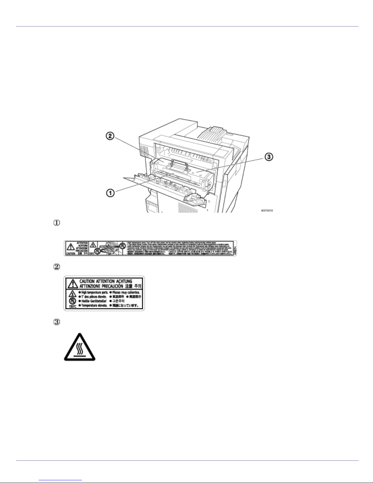
Positions of RWARNING and RCAUTION
labels
This machine has labels for RWARNING and RCAUTION at the positions
shown below. For safety, please follow the instructions and handle the machine
as indicated.
High temperature parts. Turn off the main power and be careful when replac-
ing fusing unit/removing misfed paper.
High temperature parts.
9
Page 10

Read This First
ENERGY STAR Program
As an ENERGY STAR Partner, we have determined that this machine model meets the ENERGY STAR Guidelines for energy efficiency.
The ENERGY STAR Guidelines intend to establish an international energy-saving system for
developing and introducing energy-efficient office equipment to deal with environmental issues,
such as global warming.
When a product meets the ENERGY STAR Guidelines for energy efficiency, the Partner shall
place the ENERGY STAR logo onto the machine model.
This product was designed to reduce the environmental impact associated with office equipment by means of energy-saving features, such as Low-power mode.
❖ Low-power Mode (Energy Saver mode)
This printer automatically lowers its power consumption 60 minutes after the
last operation has been completed. To exit Low-power (Energy Saver) mode,
press any key on the control panel. For more information about how to configure Energy Saver mode, see “Making Printer Settings with Control Panel”,
Software Guide as a HTML file on the CD-ROM.
❖ Specifications
Energy Saver mode Power Consumption 17 W or less
Default Time 60 minutes
Recovery Time 95 seconds or less
10
Page 11

Read This First
Manuals for This Printer
For particular functions, see the relevant parts of the manual.
❖ Setup Guide (this manual)
Provides information about printer setup and options.
❖ Maintenance Guide
Provides information about paper, replacing supplies, and dealing with paper
jams and error messages.
❖ Software Guide (HTML)
Provides basic information about installing the printer driver and software, using the printer in a network environment, and configuration and setup.
Also, provides information about configuring and monitoring printer status using software and a Web browser.
❒ Some functions cannot be used depending on your printer.
11
Page 12

Read This First
How to Read This Manual
The following set of symbols is used in this manual.
This symbol indicates a potentially hazardous situation that might result in death
or serious injury when you misuse the machine without following the instructions
under this symbol. Be sure to read the instructions, all of which are described in
the Safety Information section.
This symbol indicates a potentially hazardous situation that might result in minor
or moderate injury or property damage that does not involve personal injury
when you misuse the machine without following the instructions under this symbol. Be sure to read the instructions, all of which are described in the Safety Information section.
* The statements above are notes for your safety.
If this instruction is not followed, paper might be misfed, originals might be damaged, or data might be lost. Be sure to read this.
This symbol indicates information or preparations required prior to operating.
This symbol indicates precautions for operation, or actions to take after abnormal
operation.
This symbol indicates numerical limits, functions that cannot be used together,
or conditions in which a particular function cannot be used.
This symbol indicates a reference.
Keys that appear on the machine's display.
Keys and buttons that appear on the computer's display.
Keys built into the machine's control panel.
Keys on the computer's keyboard.
12
Page 13

Guide to the Printer
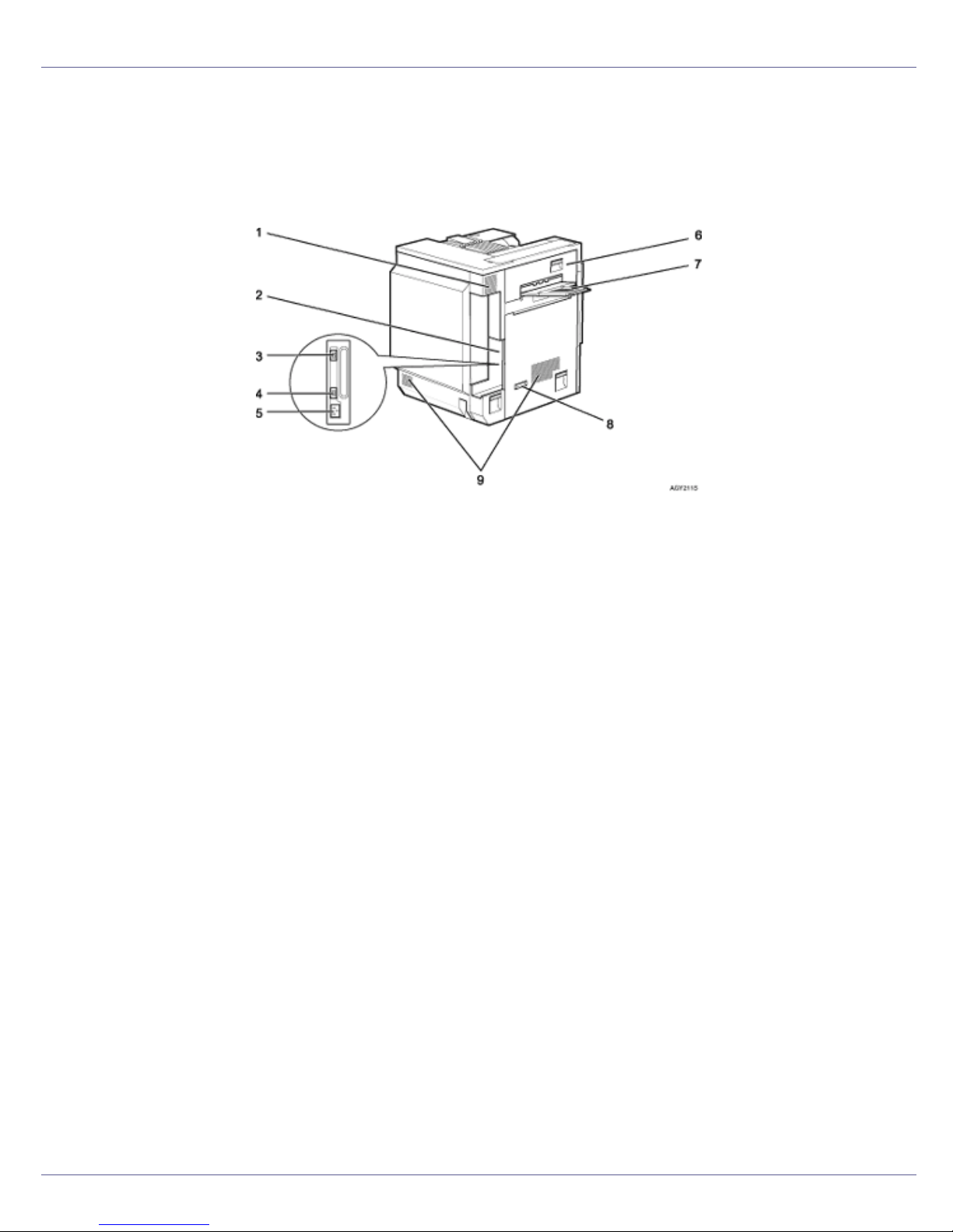
Exterior: Front View
1. Control panel
Contains keys for printer operation and a display to show printer status.
See p.20 “
Control Panel”.
2. Front cover
Open this when replacing the waste toner bottle, development unit or photoconductor
unit. A screwdriver is attached to this cover.
3. Power switch
Use this to switch between power on and off.
4. Tray 1
Loads up to 500 sheets of plain paper tray for printing. Only for letter size paper (11 ×
1
/2 K).
8
5. Tray 2
Loads up to 500 sheets of plain paper tray for printing.
6. Standard tray
Output is stacked here with the print side down.
G1307525_1.00 Copyright © 2005 13
Page 14
Guide to the Printer
❒ If printed A3 short-edge feed or 11×17 short-edge feed sheets fall off the standard
tray, raise the fence to secure them.
7. Upper right cover
Open this to replace the toner cartridge.
8. Vent
This helps keep internal components from overheating. Do not block or obstruct the
vent. Malfunctions may occur due to overheating.
9. Controller board
Slide this out to install options such as the memory unit, user account enhance unit, or
printer hard disk.
Plug cables such as the parallel interface cable and Ethernet cable into their connectors.
10. Ethernet port
Use a network interface cable to connect the printer to a network.
11. USB port
Use a USB cable to connect the printer to the host computer.
12. Expansion Card Slots
Install expansion cards in these slots. There are three slots.
When you use the expansion card, use the under slot.
13. Optional interface board slot
Insert an optional gigabit ethernet board, IEEE 1394 interface board, IEEE 802.11b interface unit, wireless interface board, IEEE 1284 interface board, or USB host interface
unit in this slot. Only one board can be inserted at a time.
14. Bypass tray extension
Pull this out to load paper in the bypass tray when its length is longer than A4 L.
15. Bypass tray
Use to print on thick paper, OHP transparencies, custom size paper, and plain paper.
Up to 100 sheets of plain paper can be loaded.
16. Vent
This helps keep internal components from overheating. Do not block or obstruct the
vent. Malfunctions may occur due to overheating.
14
Page 15

Guide to the Printer
17. Right cover
Open this to remove misfed paper.
15
Page 16
Guide to the Printer
Exterior: Rear View
❖ Basic Model Printer
1. Vent and dustproof filter
This helps keep internal components from overheating. Do not block or obstruct the
vent. Malfunctions may occur due to overheating. Remove the vent to replace the internal dustproof filter.
2. Connector board
Connect the main power cable, cables from options, etc. to the appropriate port on
this board.
3. Duplex unit port
Connect the cable for the duplex reversal unit to this port.
4. 2 tray finisher/Booklet finisher port
Connect the cable for the 2 tray finisher or the booklet finisher to this port.
5. Power port
Connect the power cable to this port and the other end to the wall outlet.
6. Upper left cover
Open this to remove misfed paper or when replacing the fusing unit.
7. External tray
Printed output is stacked here, print side up.
8. Earth leakage breaker
Prevents electric shock.
9. Vents
These help keep components inside the printer from overheating. Do not block or obstruct the vents. Malfunctions may occur due to overheating.
16
Page 17
Guide to the Printer
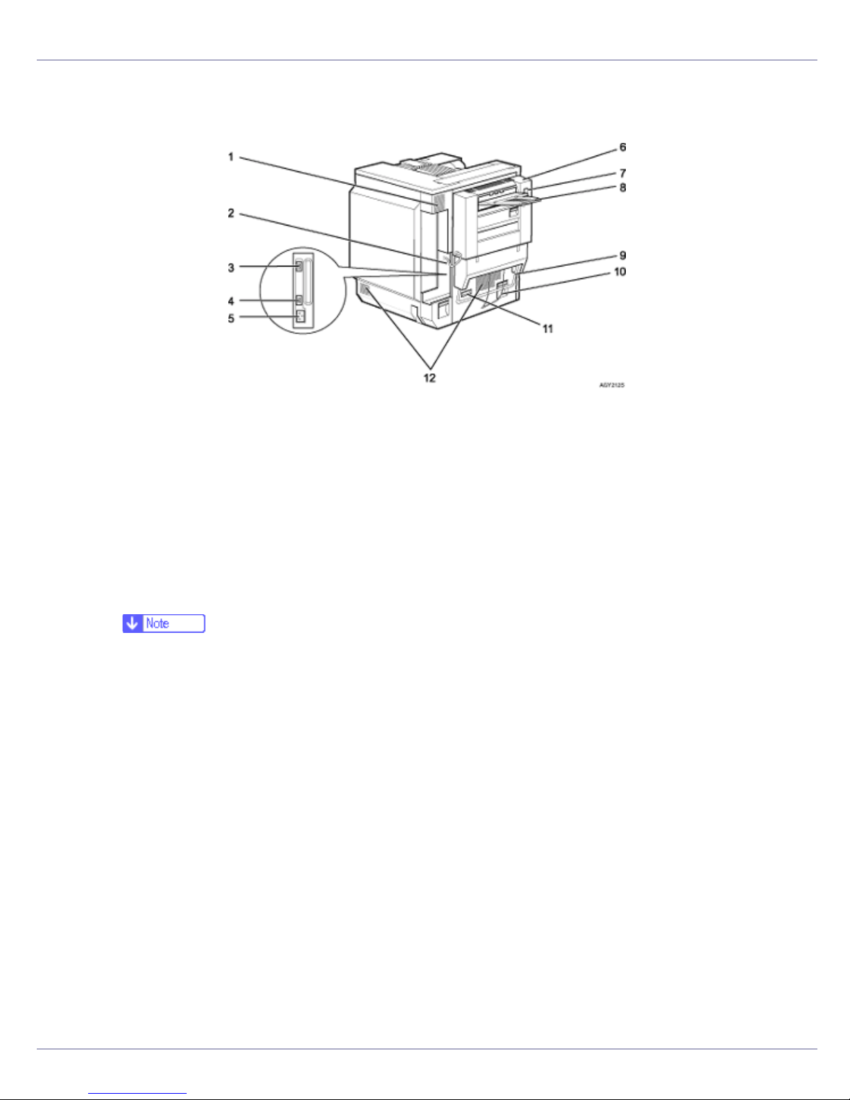
❖ Duplex Unit Standard Model Printer
1. Vent and dustproof filter
This helps keep internal components from overheating. Do not block or obstruct the
vent. Malfunctions may occur due to overheating. Remove the vent to replace the internal dustproof filter.
2. Connector board
Connect the main power cable, cables from options, etc. to the appropriate port on
this board.
3. Duplex unit port
Connect the cable for the duplex reversal unit to this port.
❒ The cable is already connected if your machine is the duplex unit standard model
printer.
4. 2 tray finisher/Booklet finisher port
Connect the cable for the 2 tray finisher or the booklet finisher to this port.
5. Power port
Connect the power cable to this port and the other end to the wall outlet.
6. Duplex reversal unit
Open this, and then the upper left cover of the printer, when removing misfed paper
or when replacing the fusing unit.
7. Duplex reversal unit open bottom
8. External tray
Printed output is stacked here, print side up.
9. Lifting handle
Pull up and hold the bar of this handle to lift the printer. Remove the paper guide before pulling up the bar.
17
Page 18

Guide to the Printer
10. Paper Guide
11. Earth leakage breaker
Prevents electric shock.
12. Vents
These help keep components inside the printer from overheating. Do not block or obstruct the vents. Malfunctions may occur due to overheating.
18
Page 19
Guide to the Printer
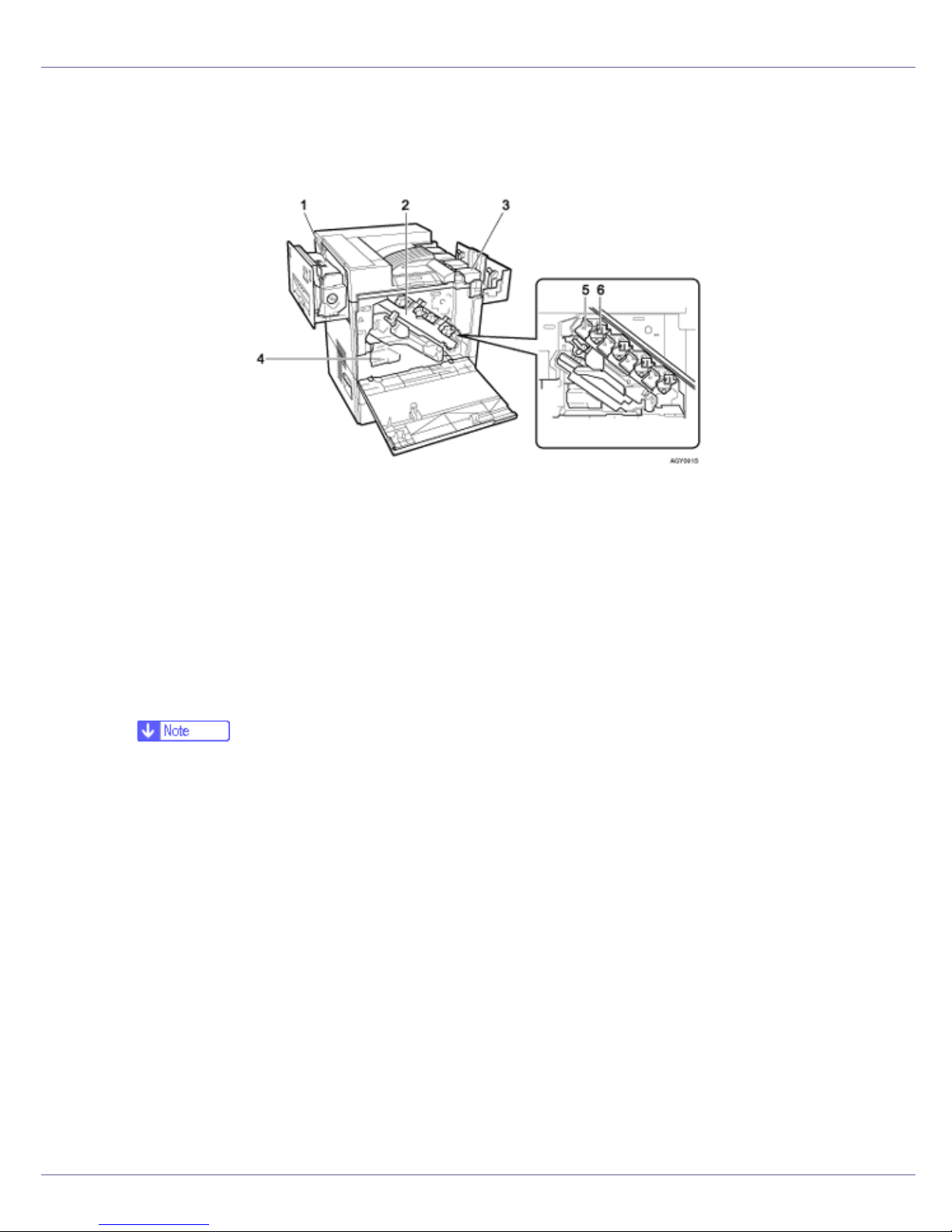
Inside
1. Fusing Unit
When “Replace Fusing Unit (C)” appears on the display, replace the fusing unit.
2. Inner cover
Open this when replacing the photoconductor unit or development unit.
3. Toner Cartridge
Loads from the printer rear, in the order of magenta (M), cyan (C), yellow (Y), and black
(K).
When “Add Toner XXX” appears on the display, replace the indicated color of the toner
cartridge.
❒ The color is displayed for XXX.
4. Waste Toner Bottle
Collects toner that is wasted during printing.
When “Replace Waste Toner (Type E)” appears on the display, replace the waste toner
bottle.
5. Photo Conductor Unit
The printer comes with one black and three color (yellow, cyan, and magenta) photoconductor units.
When “Replace Black PCU (Type F)” or “Replace Color PCU (Type A)” appears on the
display, replace the photo conductor unit.
6. Development unit
The printer comes with one black development unit and three color (yellow, cyan, magenta) development units.
When “Replace Black Dev. Unit (Type D)” or “Replace Color Dev. (Type B)” appears on
the display, replace the development unit.
19
Page 20
Guide to the Printer
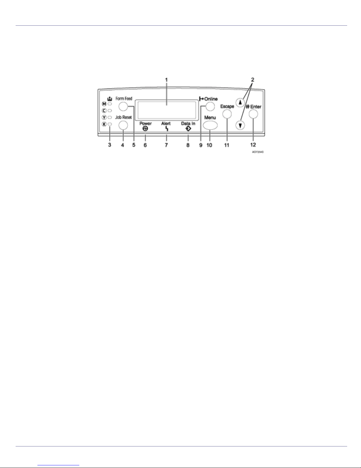
Control Panel
1. Display
Displays current printer status and error messages.
For details about error messages, see Maintenance Guide.
2. {U} {T} keys
Use these keys to increase or decrease values on the display when making settings.
Keep the key pressed to quicken scrolling, and increase or decrease values on the dis-
play in units of 10.
3. Toner End LED
The color of the lit LED indicates toner status for each color.
A yellow light indicates the toner amount is approaching exhaustion. A red light indicates
the toner cartridge needs to be replaced.
4. {Job Reset} key
When the printer is online, press this key to cancel an ongoing print job.
5. {Form Feed} key
When the printer is offline, press this to print all data left in the printer's input buffer.
You can use this to force the printer to print data received in the online status when the
paper size or type does not match the actually set size or type.
6. Power indicator
This indicator remains lit while the power is on. It is unlit when the power is off or while
the printer is in Energy Saver mode.
7. Alert indicator
Lights up whenever a printer error occurs. A red light indicates an error has occurred that
makes printing impossible; the yellow light indicates a potential error during printing.
If the red light is on, follow the instructions that appear on the display.
8. Data In indicator
Blinks when the printer is receiving data from a computer. The Data In indicator is lit if
there is data to be printed.
20
Page 21

Guide to the Printer
9. {Online} key
Indicates whether the printer is online or offline. Press this to switch between online and
offline.
When the lamp is lit, the printer is online, enabling data reception from the host computer.
When the lamp is unlit, the printer is offline, disabling data reception from the host computer.
Press to return to the ready condition.
10. {Menu} key
Press this key to make and check the current printer settings.
For details, See “Making Printer Settings Using the Control Panel”, Software Guide.
11. {Escape} key
Press this key to return to the previous condition on the display.
12. {# Enter} key
Press this key to execute menu items selected on the display.
21
Page 22
Setting Up
Where to Put the Printer
The printer's location should be carefully chosen because environmental conditions greatly affect its performance.
• Confirm the wall outlet is near the machine and freely accessible, so
that in the event of emergency, it can be unplugged easily.
• Only connect the machine to the power source described in the manual.
• Avoid multi-wiring.
• Do not damage, break or make any modifications to the power cord.
Do not place heavy objects on it, pull it hard or bend it more than necessary. These actions could cause an electric shock or fire.
• Enclosed set of power cord is only for the use with this product and
should not be used with any other electronic equipment or appliances.
Do not use any other power cord with this product. They could cause
electric shock or fire.
• Do not handle the plug with wet hands. Doing so might cause an electrical
shock.
• Keep the machine in an area that is within optimum environmental conditions. Operating the machine in an environment that is outside the recommended ranges of humidity and temperature can cause an electrical fire
hazard. Keep the area around the socket free of dust. Accumulated dust
can become an electrical fire hazard.
• Place the machine on a strong and level surface. Otherwise, it might fall and
injure someone.
• If you use the machine in a confined space, ensure there is continuous air
circulation.
G1307525_1.00 Copyright © 2005 22
Page 23
Setting Up
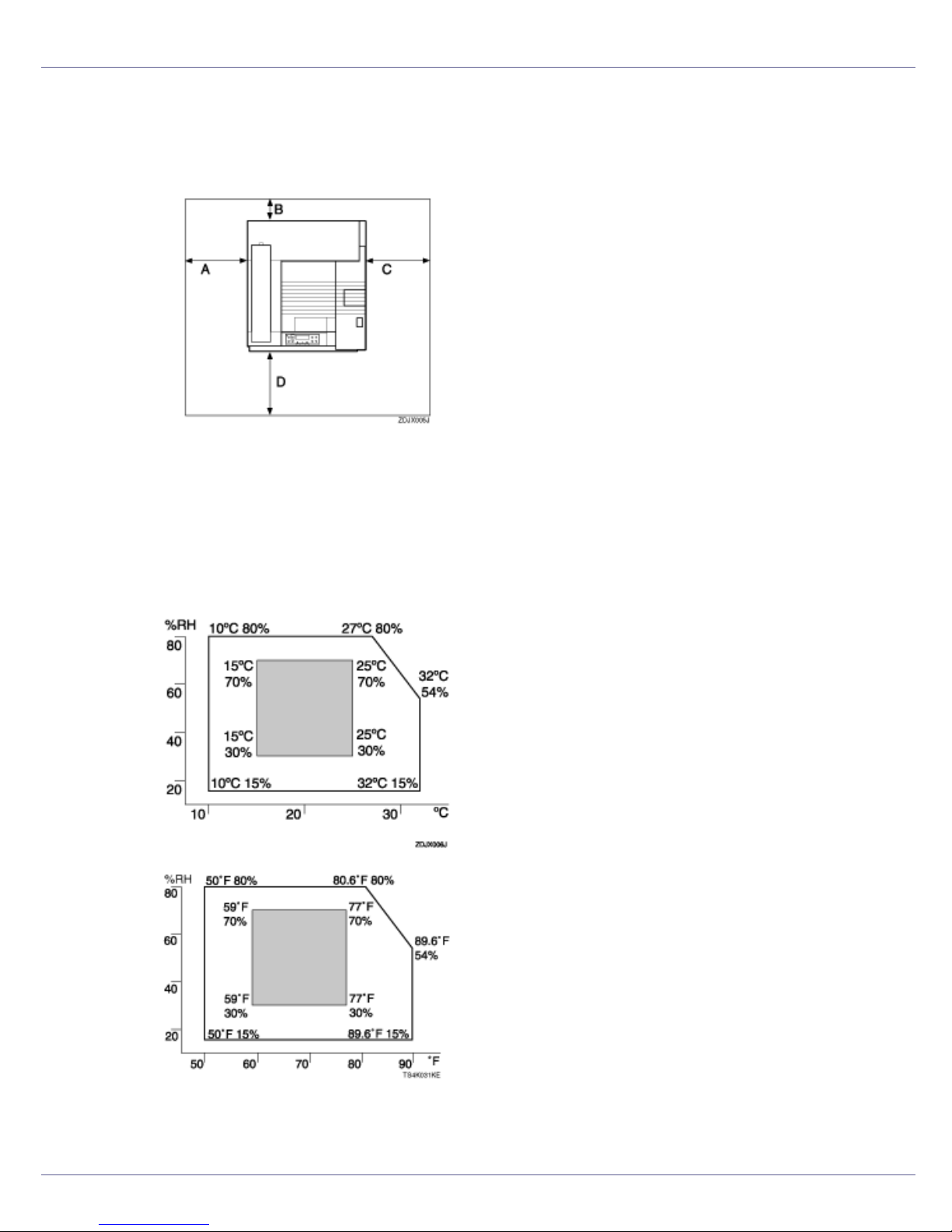
❖ Space Required for Installation
Leave enough space around the printer. This space is necessary to operate
the printer. The recommended (or minimum) space requirements are as follows:
A: 50 cm (19.7 inches) or more
B: 10 cm (4 inches) or more
C: 10 cm (4 inches) or more
D: 70 cm (27.6 inches) or more
❖ Optimum Environmental Conditions
Permissible and recommended temperature and humidity ranges are as follows:
• White area: Permissible Range
• Gray area: Recommended Range
23
Page 24

Setting Up
❒ The machine must be level within 5 mm, 0.2” from both front to rear and left
to right.
❒ To avoid possible build-up of ozone, locate this machine in a large well ven-
tilated room that has an air turnover of more than 30 m
3
/hr/person.
❒ When you use this machine for a long time in a confined space without
good ventilation, you may detect an odd smell. To keep the workplace
comfortable, we recommend you keep it well ventilated.
❖ Environments to Avoid
❒ Areas exposed to direct sunlight or strong light
❒ Dusty areas
❒ Areas with corrosive gases
❒ Areas that are excessively cold, hot, or humid
❒ Locations near air conditioners or humidifiers
❒ Locations near other electronic equipment
❒ Locations subject to frequent strong vibration
❖ Power Source
Connect the power cable to a power source of the following specification:
• Basic model printer: 120 V, 60 Hz, 11 A or more
• Duplex unit standard model printer: 120 V, 60 Hz, 12 A or more
24
Page 25
Setting Up
Checking the Contents of the Box
Follow the procedure below to verify the items that come with the printer.
❒ Ensure that the box contains all items listed below. If there are any missing or
defective items, contact your sales representative.
❖ Manuals and CD-ROMs
Setup Guide (This manual)
Maintenance Guide
CD-ROM “Printer Drivers and Utilities”
CD-ROM “Display-Version Manuals (HTML)”
CD-ROM “Print-Version Manuals (PDF)”
CD-ROM “Document Management Utility”
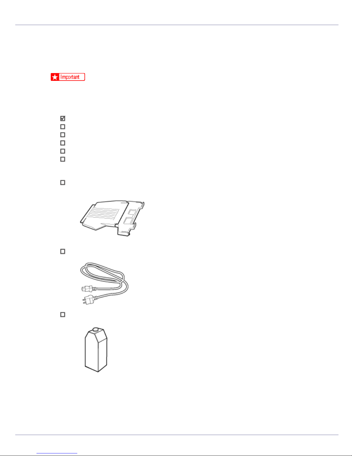
❖ Parts
External Tray
Power Cable
Black Toner Cartridge (K)
25
Page 26
Setting Up
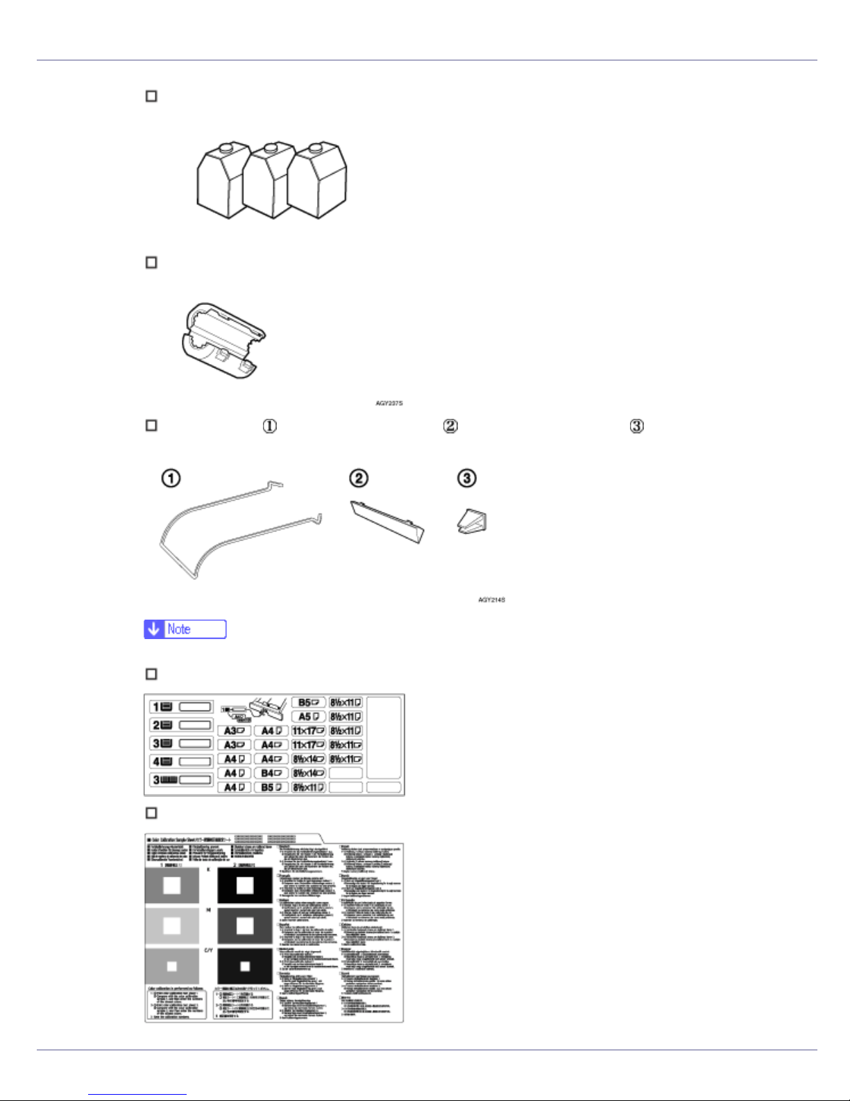
Magenta (M), Cyan (C), Yellow (Y) Toner Cartridges
Ferrite Core
Paper guide ( ), Paper guide cover ( ), Paper guide holder ( )
❒ This items are supplied with the duplex unit standard model.
Paper Feed Unit Labels
Color Calibration Sample Sheet
26
Page 27

Setting Up
Additional Documentation
❒ This package does not include an interface cable. Please purchase one to use
with your host computer. See “Appendix”, Maintenance Guide.
27
Page 28

Setting Up
Unpacking
To protect it from shock and vibration during transit, this printer comes packaged
in cushioning foam and secured with tape. Remove these protective materials
after bringing the machine to where it will be installed.
• When lifting the machine, use the inset grips on both sides. The printer
could break or cause an injury if dropped.
• Place no objects on the front cover.
❒ Basic model printer weighs approximately 83.3 kg (183.7 lb.), duplex unit
standard model printer weighs approximately 92.5 kg (203 lb.).
A Remove the plastic bag.
B Lift the printer with four people by using the inset grips on both sides of
the printer.
❒ To move the printer, four people should hold the handles located on the
sides.
❒ Leave the tape holding the paper feed tray and cover in place while moving
the printer.
❒ Lower the machine slowly and carefully to prevent trapping your hands.
28
Page 29
Setting Up
❒ When moving the duplex unit standard model, pull up the bar of the lifting
handle, located on the left side of the printer. Holding the bar, lift the printer.
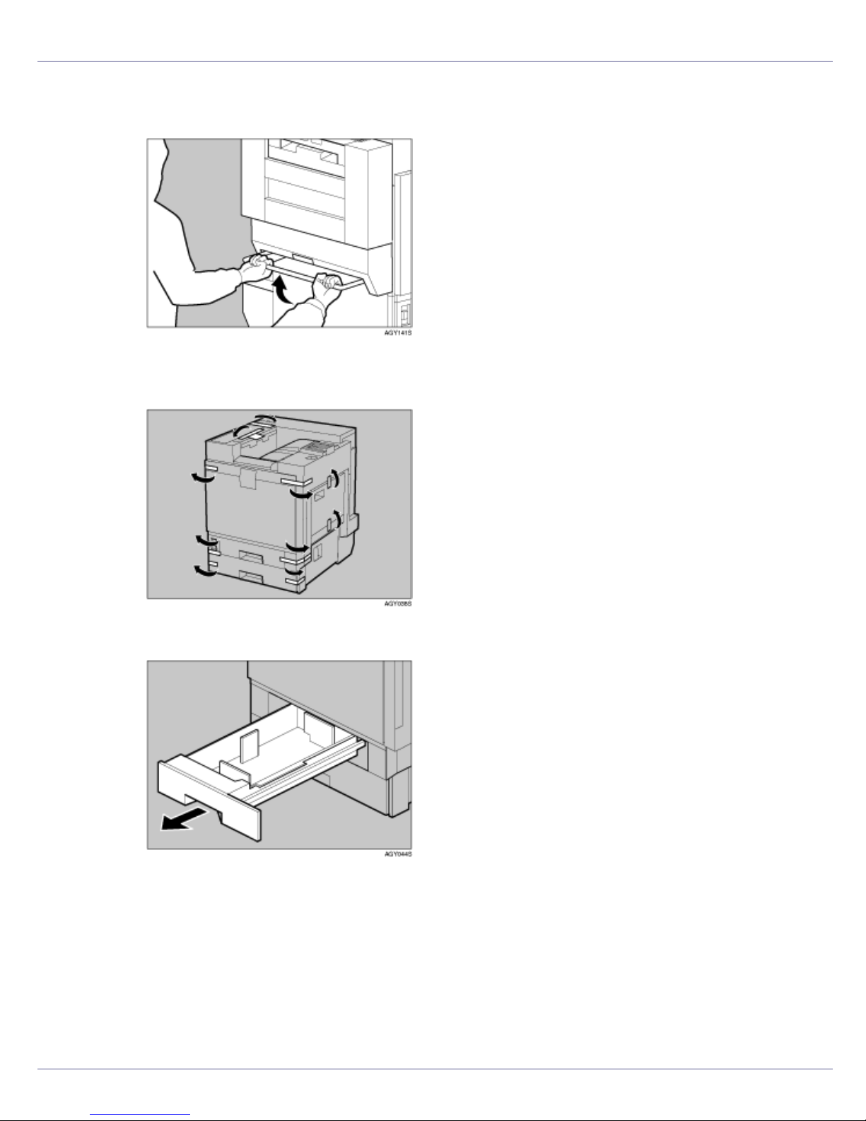
C Remove the adhesive tape from the printer body. Remove the cardboard
taped to the standard tray.
D Open tray 1.
29
Page 30
Setting Up
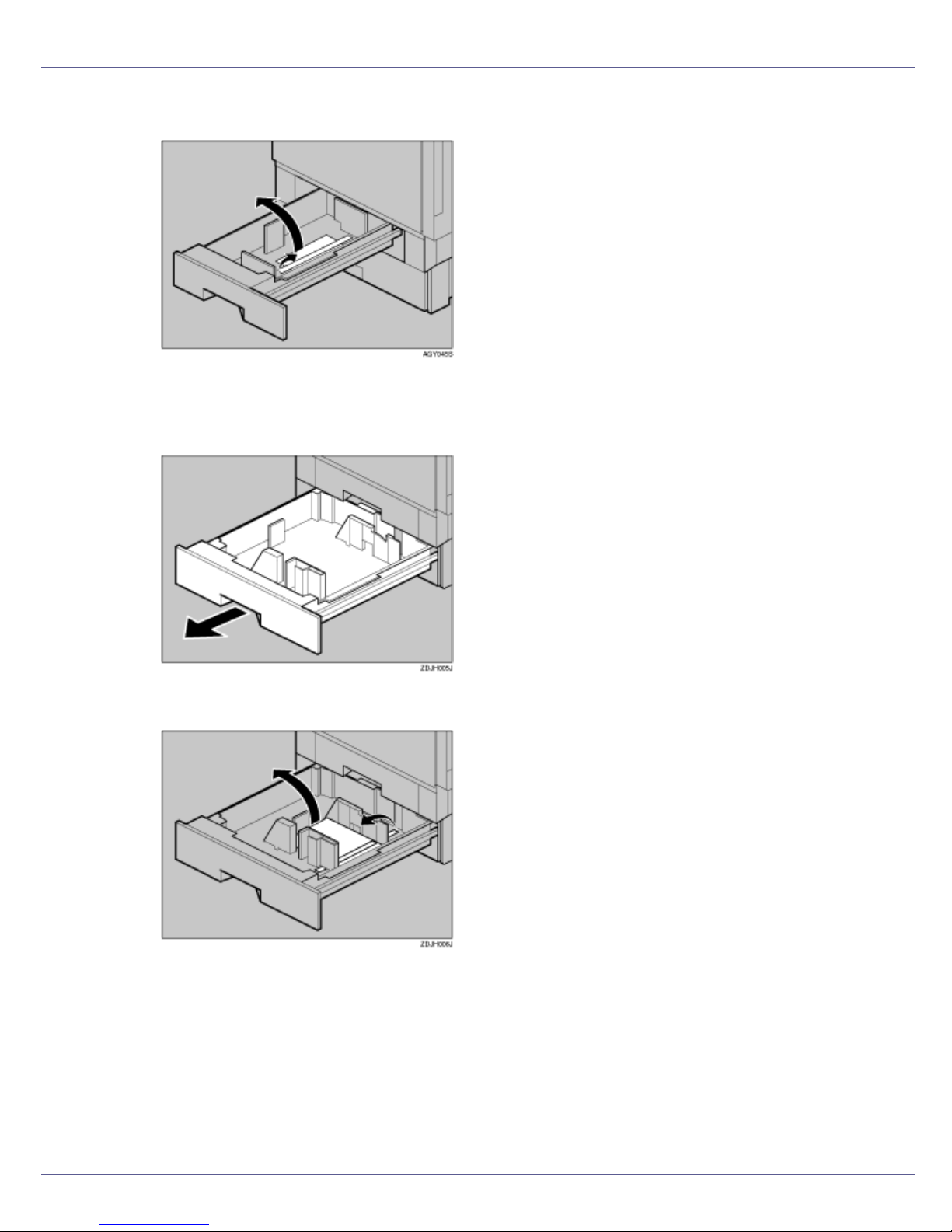
E Remove the adhesive tape and sheet of paper.
F Close tray 1 slowly.
G Open tray 2.
H Remove the adhesive tape and sheet of paper.
I Close tray 2 slowly.
30
Page 31

Setting Up
J Open the front cover slowly by pulling down using the upper left and
right sides.
❒ Do not place objects on the opened front cover.
K Remove the adhesive tape.
31
Page 32

Setting Up
L Turn the green lever clockwise.
M Hold down the printer’s inner cover, grasp the pieces of tape protruding
from the development unit, and then slowly pull them out horizontally.
❒ Be sure to pull out all four pieces of tape to avoid printer malfunction during
operation.
❒ The removed tape is dirty. Be careful not to let it touch your hands or
clothes.
N Remove the securing pin, as shown, from the transfer unit. Pinch it, and
then pull it out.
32
Page 33

Setting Up
O Close the front cover slowly by pushing the two areas on the left and
right.
P Put labels “1” and “2” on the front of the paper trays.
Q A sticker, stating that paper for an ink-jet printer cannot be used with
this printer, is supplied. Please attach this to the near right corner of the
printer's top [A], so it is easy to see.
(For the duplex unit standard model, the following procedure is also necessary:)
33
Page 34

Setting Up
R Remove the protective sheet from inside the duplex reversal unit (print-
ing unit). Push the lock/unlock button and open the unit slowly.
S Remove the adhesive tape and the protective sheet.
T Close the duplex reversal unit.
U Attach the paper guide to the duplex reversal unit stand. Hold both sides
of the guide carefully and insert the ends of the guide into the holes of
the stand ( ). Then fit the paper guide cover in the proper position ( ).
❒ Before attaching the paper guide, you must lower the bar of the lifting han-
dle.
34
Page 35

Setting Up
V Secure the attached paper guide.
35
Page 36

Setting Up
Installing the Toner Cartridge
The following procedure describes how to install the toner cartridge.
• Do not incinerate spilled toner or used toner. Toner dust is flammable
and might ignite when exposed to an open flame.
• Disposal should take place at an authorized dealer or an appropriate
collection site.
• If you dispose of the used toner cartridges yourself, dispose of them
according to local regulations.
• Do not store toner, used toner, or toner containers in a place with an
open flame. The toner might ignite and cause burns or a fire.
• Keep toner (used or unused) and the toner cartridge out of reach of children.
• If toner or used toner is inhaled, gargle with plenty of water and move into
a fresh air environment. Consult a doctor if necessary.
• If your skin comes into contact with toner or used toner, wash the affected
area thoroughly with soap and water.
• If toner or used toner gets into your eyes, flush immediately with large
amounts of water. Consult a doctor if necessary.
• If toner or used toner is swallowed, dilute by drinking a large amount of water. Consult a doctor if necessary.
• Avoid getting toner on your clothes or skin when removing a paper jam or
replacing toner. If your skin comes into contact with toner, wash the affected
area thoroughly with soap and water.
• If toner gets on your clothing, wash with cold water. Hot water will set the
toner into the fabric and may make removing the stain impossible.
❒ When you first use this printer, use the four toner cartridges packaged with the
printer.
❒ The toner cartridges that comes with the printer will allows you to print up to
about 12,000 pages in black, and about 5,000 pages in color. These numbers
were obtained from printing A4K 3% charts, but the actual number of pages
will differ depending on the paper type, size, contents and settings.
❒ Toner Cartridges (consumable) are not covered by warranty. However, if
there is problem, contact the store where they ware purchased.
36
Page 37

Setting Up
❒ Toner cartridge mouths may be dirtied during quality inspection.
A Open the upper right cover.
B Take out the toner cartridges from the box.
❒ The black (K) toner cartridge contains more toner than the others.
C Shake the toner cartridge back and forth five or six times.
D Holding the toner cartridge with the metal contact area in front, insert in
the direction of the arrow.
37
Page 38

Setting Up
Insert each cartridge into the same color slot.
❒ Be careful not to touch the metal contact point with your fingers.
E Insert the toner cartridge slowly, until the green hook snaps on the metal
contact area.
❒ Do not insert and remove toner cartridges repeatedly, as this could result
in toner leakage.
F Use the same procedure to insert the remaining three toner cartridges.
G Close the upper right cover.
38
Page 39

Setting Up
❒ Do not turn off the power switch while “Loading Toner...” appears on the
display. Doing so results in malfunction.
39
Page 40

Setting Up
Loading Paper
The following describes how to load paper into the standard paper tray (Tray 1).
• Do not pull out the paper tray forcefully. If you do, the tray might fall and
cause an injury.
❒ Tray 1 is letter size paper (11 × 81/2 K) only. Load only letter size paper (11
❒ Do not mix different types of paper in a single paper tray.
× 8
1
/2 K).
A Slowly slide the paper tray out, until it stops.
B Align all four sides of the paper stack, and then load it in the tray.
❒ To avoid paper jams, make sure paper is not stacked above the limit mark
inside the tray. Misfeeds might occur.
C Slowly slide the paper tray back, until it stops.
For details about size and feed orientation of paper that can be loaded in
the tray, see “Paper and Other Media”, Maintenance Guide.
40
Page 41

Setting Up
For details about loading paper in the bypass tray, see “Loading Paper in
the Bypass Tray”, Maintenance Guide.
41
Page 42

Setting Up
Turning the Power On
Follow the procedure below to turn the power on.
• Plug and unplug the power cable with dry hands, or an electric shock
could occur.
A Make sure the power switch is set to “b” off.
B Connect the power cable to the connector on the back of the printer.
C Plug in the power cable.
❒ Make sure the power cable is plugged securely into the wall outlet.
❒ Turn the power switch off when plugging and unplugging the power plug.
42
Page 43

Setting Up
D Turn the power switch to “a” On.
The power indicator on the control panel lights up.
❒ Wait until “Ready” appears on the display panel.
❒ The machine may make a noise while initializing. This noise does not indi-
cate a malfunction.
❒ Do not turn off the power switch until initializing is completed. Doing so re-
sults in malfunction.
43
Page 44

Setting Up
Selecting the Display Language
Select a language using the procedure described here.
The message for the selected language will appear on the display. If you want to
use the display in English, the following procedures are unnecessary.
❒ The default setting is English.
A Press the {Menu} key.
The [Menu] screen appears on the display.
B Press the {U} or {T} key to display “Language”.
Menu:
Language
C Press the {# Enter} key.
The following message appears on the display:
Language:
*English
D Press the {U} or {T} key until the language you want to select appears.
44
Page 45

Setting Up
E Press the {# Enter} key. Wait for two seconds.
The [Menu] screen appears on the display.
F Press the {Online} key.
The initial screen appears.
Ready
45
Page 46

Setting Up
Test Printing
The following explains the procedure for test printing of the configuration page.
Test print in order to verify that the printer is working normally. Test printing
checks printer performance only; it does not test the connection to the computer.
A Press the {Menu} key.
The [Menu] screen appears on the display.
Menu:
Paper Input
B Press the {U} or {T} key to display [List/Test Print], and then press the {#
Enter} key.
Menu:
List/Test Print
The menu for selecting the contents to be test printed appears.
C Press the {U} or {T} key to display the [Config. Page], and then press the
{# Enter} key.
List/Test Print
Config. Page
The following message appears and the configuration page is printed.
Printing...
46
Page 47

Setting Up
❒ If printing is not normal, check to see if an error message appears on the
display. If there is an error message, see “Troubleshooting”, Maintenance
Guide.
D Check the options.
❒ For details about the configuration page, see “Interpreting the Configura-
tion Page”, Software Guide.
E Press the {Online} key.
The initial screen appears.
Ready
47
Page 48

Installing Options
Available Options
This section describes how to install options.
By installing options, you can improve the printer performance and have an expanded variety of features to use. For the specifications of each option, see
Maintenance Guide.
• Before installing options, the machine should be turned off and unplugged
for at least an hour. Components inside the machine become very hot, and
can cause a burn if touched.
• Before moving the machine, unplug the power cable from the outlet. If the
cable is unplugged abruptly, it could become damaged. Damaged plugs or
cables can cause an electrical or fire hazard.
• When lifting the machine, use the grips on both sides. The machine could
break or cause an injury if dropped.
❒ The voltage rating of the connector for options is 24 V DC or less.
Option List
The following is a list of options for this printer. Some printer models come with
the expansion Hard Disk Drive and the duplex unit attached as default.
Basic model printer Duplex unit standard mod-
el printer
Paper Feed Unit Type 7300 (500 × 1)
Paper Feed Unit Type 7300 (500 × 2)
Paper Bank Type 7300
SR960 (2 Tray Finisher)
SR950 (Booklet Finisher)
Duplex Unit Type 7100
Printer Hard Disk Type 7100
Memory Unit Type C (SDRAM module)
Gigabit Ethernet Type 7300
IEEE 802.11b Interface Unit Type H
IEEE 1394 Interface Board Type B
Bluetooth Interface Unit Type 3245
G1307525_1.00 Copyright © 2005 48
Page 49

Installing Options
Basic model printer Duplex unit standard mod-
el printer
IEEE 1284 Interface Board Type A
USB Host Interface Unit Type 7300
User Account Enhance Unit Type E
Camera direct print card Type 7300
: Available option
: Standard equipment
❒ Only one of the three types of paper feed unit can be installed at the same
time.
❒ To install a finisher, contact your service representative.
❒ The printer's ethernet and USB ports are not available when the gigabit eth-
ernet board is attached to the printer. Use the ethernet port and USB port
mounted on the board instead.
Option Installation Flow Chart
We recommend you install multiple options in the following order:
A Attach the 500, 1000-sheet paper feed unit, or 2000-sheet large capacity
tray. (Paper Feed Unit Type 7300, Paper Bank Type 7300)
Attach the paper feed unit to the bottom of the printer.
You can install the Paper Feed Unit Type 7300 (500 × 1), Paper Feed Unit
Type 7300 (500 × 2) or Paper Bank Type 7300.
If you install the Paper Bank Type 7300, you can load up to 3,100 sheets of
paper at once.
B Install the SDRAM module. (Memory Unit Type C)
Install the module to the SDRAM module slot on the controller board.
There are two types of memory unit: 64 MB, 128 MB, and 256 MB.
C Install the user account enhance unit. (User Account Enhance Unit Type
E)
Install the module to the user account enhance unit slot of the controller
board.
D Install the hard disk drive. (Printer Hard Disk Type 7100)
Install the hard disk drive to the controller board.
49
Page 50

Installing Options
E Install the gigabit ethernet board, IEEE 802.11b interface unit, IEEE 1394
interface board, IEEE 1284 interface board, Bluetooth interface unit, or
USB host interface unit.
Install the gigabit ethernet board, IEEE 802.11b interface unit, IEEE 1394 interface board, IEEE 1284 interface board, Bluetooth interface unit, or USB
host interface unit on the controller board.
The IEEE 1394 interface board and standard ethernet interface cannot be
used at the same time.
Only one of the following can be installed.
• Gigabit Ethernet Type 7300
• IEEE 802.11b Interface Unit Type H
• IEEE 1394 Interface Board Type B
• IEEE 1284 Interface Board Type A
• Bluetooth Interface Unit Type 3245
• USB Host Interface Unit Type 7300
F Install the camera direct print card. (Camera direct print card Type 7300)
Insert the network data protection unit into the SD card slot on the controller
board.
G Attach the duplex unit. (Duplex Unit Type 7100)
Attach the duplex reversal unit to the left side of the printer, and the duplex
feed unit inside the printer.
H Attach the 2 tray finisher or the booklet finisher. (SR950, SR960)
Attach the 2 tray finisher or the booklet finisher to the left side of the printer.
You cannot install the 2 tray finisher or the booklet finisher unless both the paper feed unit and duplex unit options are installed.
To install a finisher, contact your service representative.
Installing Options
Install options in the positions shown in the illustration.
50
Page 51

Installing Options
❖ Exterior
1. Paper Feed Unit Type 7300 (500 × 1)
Loads up to 500 sheets (500 sheets × 1 column) of paper.
See p.55 “
Installing Paper Feed Unit Type 7300 (500 × 1)”.
2. Paper Feed Unit Type 7300 (500 × 2)
Loads up to 1,000 sheets (500 sheets × 2 columns) of paper.
See p.60 “
Installing Paper Feed Unit Type 7300 (500 × 2)”.
3. Paper Bank Type 7300 (2000-sheet Large Capacity Tray)
Loads up to 2,000 sheets (2,000 sheets × 1 column) of paper.
See p.65 “
Installing Paper Bank Type 7300 (2000-sheet Large Capacity Tray)”.
4. SR960 (2 Tray Finisher) / SR950 (Booklet Finisher)
To install a finisher, contact your service representative.
5. Duplex Reversal Unit
Flips over the paper during duplex printing. Install the unit on the left side of the printer.
See p.108 “
Installing the Duplex Reversal Unit”.
6. Duplex Feed Unit
Transports paper during duplex printing. Install the unit inside the printer.
See p.112 “
❒ You cannot install the 2 tray finisher or the booklet finisher unless both the
paper feed unit and duplex unit options are attached.
Installing the Duplex Feed Unit”.
❒ Some printer models come with the duplex unit attached as default.
51
Page 52

Installing Options
❖ Interior
1. Memory Unit Type C (SDRAM Module)
Install 64 MB, 128 MB, or 256 MB RAM into the controller board slot.
See p.71 “
Attaching Memory Unit Type C (SDRAM Module)”.
2. Optional Interface Board/Unit
• Gigabit Ethernet Type 7300
See p.84 “
• IEEE 802.11b Interface Unit Type H
See p.87 “
• Bluetooth Interface Unit Type 3245
See p.91 “
• IEEE 1394 Interface Board Type B
See p.94 “
• IEEE 1284 Interface Board Type A
See p.97 “
• USB Host Interface Unit Type 7300
See p.101 “
Attaching Gigabit Ethernet Type 7300”.
Attaching IEEE 802.11b Interface Unit Type H”.
Attaching Bluetooth Interface Unit Type 3245”.
Attaching IEEE 1394 Interface Board Type B”.
Attaching IEEE 1284 Interface Board Type A”.
Attaching USB Host Interface Unit Type 7300”.
3. Camera direct print card Type 7300
See p.99 “Attaching Camera direct print card Type 7300”.
4. User Account Enhance Unit Type E
See p.75 “Attaching User Account Enhance Unit Type E”.
5. Printer Hard Disk Type 7100
See p.79 “Attaching Printer Hard Disk Type 7100”.
❒ You can have one of the following types of extension board installed at the
same time: Gigabit Ethernet Type 7300, IEEE 802.11b Interface Unit Type H,
IEEE 1394 Interface Board Type B, IEEE 1284 Interface Board Type A, Bluetooth Interface Unit Type 3245, or USB Host Interface Unit Type 7300.
52
Page 53

Installing Options
❒ Some printer models come with the expansion printer hard disk installed as
default.
For the specifications of each option, see Maintenance Guide.
53
Page 54

Installing Options
Using the Screwdriver
The special screwdriver used for attaching options is attached to the inside of the
front cover.
A Open the printer’s front cover, and then remove the provided screwdriv-
er.
B Insert the screw into the screwdriver.
By pushing the screw into the screwdriver, you can work without having to
worry about dropping the screw.
❒ After using the screwdriver, return it to its original position on the inside of
the front cover.
54
Page 55

Installing Options
Installing the Paper Feed Unit
If you have already installed the optional duplex unit, 2 tray finisher, or booklet
finisher, remove all these options before installing the optional paper feed
unit.
❒ Before installation, check the orientation of the paper feed unit or 2000-sheet
large capacity tray you want to place.
❒ When installing multiple options, install the paper feed unit first.
❒ Four people are needed to install the paper feed unit. Start installation when
all four people are ready.
• When moving the machine, each person should hold a handle, located on
two sides of the printer, and then lift slowly. Lifting carelessly or dropping it
may cause injury.
❒ Basic model printer weighs approximately 83.3 kg (183.7 lb.), duplex unit
standard model printer weighs approximately 92.5 kg (203 lb.).
Installing Paper Feed Unit Type 7300 (500 × 1)
• When moving the paper feed unit, hold the bottom of both sides, and then
lift slowly. Lifting carelessly or dropping it may cause injury.
❒ The 500-sheet paper feed unit weighs approximately 18 kg (39.7 lb.).
A Turn off the power then unplug the power cable, and then interface ca-
ble.
55
Page 56

Installing Options
B Remove the adhesive tape.
C Lifting the printer.
❒ To move the printer, four people should hold the handles located on the
sides.
❒ When moving the duplex unit standard model, remove the paper guide of
the duplex reversal unit, pull up the bar of the lifting handle located on the
left side of the printer. Holding the bar, lift the printer.
56
Page 57

Installing Options
D Adjust the four corners of the printer to those of the 500-sheet paper
feed unit, and then lower the printer slowly into place.
E Open the tray of the 500-sheet paper feed unit. Remove the adhesive
tape and sheet of paper, and the corrugated paper inside the tray, as
shown.
F Take out the packaged items, making sure there are two thumb screws
and one mounting bracket. Close the tray of the 500-sheet paper feed
unit firmly.
57
Page 58

Installing Options
G Slowly pull out tray 2 while lifting up a little.
H Fasten one thumb screw. A coin can be used to fasten the screws.
I Slowly slide tray 2 back into the printer, until it stops.
J Open the right cover of the 500-sheet paper feed unit.
58
Page 59

Installing Options
K Hook the mounting bracket to the hole, as shown.
L Fasten the bracket with the other thumb screw. A coin can be used to
fasten the screws.
M Close the right cover of the 500-sheet paper feed unit.
N For the duplex unit standard model, Attach the paper guide to the duplex
reversal unit stand. Hold both sides of the guide carefully and insert the
ends of the guide into the holes of the stand ( ). Then fit the paper guide
cover in the proper position ( ).
❒ Before attaching the paper guide, you must lower the bar of the lifting han-
dle.
59
Page 60

Installing Options
O Secure the attached paper guide.
P Stick label “3” above the handle on the front of the 500-sheet paper feed
unit.
❒ After finishing installation, check the 500-sheet paper feed unit is properly
installed: print the configuration page from the “List/Test Print” menu. If it is
installed properly, you will see “Paper Feed Unit (Tray 3)” for “Connection
Equipment”.
❒ If the paper feed unit is not installed properly, reinstall it from the start of
the procedure. If you cannot install it properly even after attempting reinstallation, contact your sales or service representative.
For details about printing the configuration page, see p.46 “Test Printing”.
Installing Paper Feed Unit Type 7300 (500 × 2)
• When moving the paper feed unit, hold the bottom of both sides, and then
lift slowly. Lifting carelessly or dropping it may cause injury.
❒ The 1000-sheet paper feed unit weighs approximately 25 kg (55.2 lb.).
60
Page 61

Installing Options
A Turn off the power then unplug the power cable, and then interface ca-
ble.
B Remove the adhesive tape.
C Lifting the printer.
❒ To move the printer, four people should hold the handles located on the
sides.
❒ When moving the duplex unit standard model, remove the paper guide of
the duplex reversal unit, pull up the bar of the lifting handle located on the
left side of the printer. Holding the bar, lift the printer.
61
Page 62

Installing Options
D Adjust the four corners of the printer to those of the 1000-sheet paper
feed unit, and then slowly lower the printer into place.
E Open the tray of the 1000-sheet paper feed unit. Remove the adhesive
tape and sheet of paper, and the corrugated paper inside the tray, as
shown.
F Take out the packaged items, making sure there are two thumb screws
and one mounting bracket. Close the tray of the 1000-sheet paper feed
unit firmly.
62
Page 63

Installing Options
G Slowly pull out tray 2 while lifting up a little.
H Fasten one thumb screw. A coin can be used to fasten the screws.
I Slowly slide tray 2 back into the printer, until it stops.
J Open the right cover of the 1000-sheet paper feed unit.
63
Page 64

Installing Options
K Hook the mounting bracket to the hole, as shown.
L Fasten the bracket with the other thumb screw. A coin can be used to
fasten the screws.
M Close the right cover of the 1000-sheet paper feed unit.
N For the duplex unit standard model, Attach the paper guide to the duplex
reversal unit stand. Hold both sides of the guide carefully and insert the
ends of the guide into the holes of the stand ( ). Then fit the paper guide
cover in the proper position ( ).
❒ Before attaching the paper guide, you must lower the bar of the lifting han-
dle.
64
Page 65

Installing Options
O Secure the attached paper guide.
P Stick labels “3” and “4” above the handles on the front of the 1000-sheet
paper feed unit.
❒ After finishing installation, check the 1000-sheet paper feed unit is properly
installed: print the configuration page from the “List/Test Print” menu. If it is
installed properly, you will see “Paper Feed Unit (Tray 3 & Tray 4)” for
“Connection Equipment”.
❒ If the paper feed unit is not installed properly, repeat the procedure from
the start. If you cannot install it properly even after attempting reinstallation,
contact your sales or service representative.
For details about printing the configuration page, see p.46 “Test Printing”.
Installing Paper Bank Type 7300 (2000-sheet Large Capacity Tray)
• When moving the paper feed unit, hold the bottom of both sides, and then
lift slowly. Lifting carelessly or dropping it may cause injury.
❒ The 2000-sheet large capacity tray weighs approximately 25 kg (55.2 lb.).
65
Page 66

Installing Options
A Turn off the power then unplug the power cable, and then interface ca-
ble.
B Remove the adhesive tape.
C Lifting the printer.
❒ To move the printer, four people should hold the handles located on the
sides.
❒ When moving the duplex unit standard model, remove the paper guide of
the duplex reversal unit, pull up the bar of the lifting handle located on the
left side of the printer. Holding the bar, lift the printer.
66
Page 67

Installing Options
D Adjust the four corners of the printer to those of the 2000-sheet large ca-
pacity tray, and then slowly lower the printer into place.
E Take out the packaged items, making sure there are two thumb screws
and one mounting bracket. Close the tray of the 2000-sheet large capacity tray firmly.
F Slowly pull out tray 2 while lifting up a little.
67
Page 68

Installing Options
G Fasten one thumb screw. A coin can be used to fasten the screws.
H Slowly slide tray 2 back into the printer, until it stops.
I Open the right cover of the 2000-sheet large capacity tray.
J Hook the mounting bracket to the hole, as shown.
68
Page 69

Installing Options
K Fasten the bracket with the other thumb screw. A coin can be used to
fasten the screws.
L Close the right cover of the 2000-sheet large capacity tray.
M For the duplex unit standard model, Attach the paper guide to the duplex
reversal unit stand. Hold both sides of the guide carefully and insert the
ends of the guide into the holes of the stand ( ). Then fit the paper guide
cover in the proper position ( ).
❒ Before attaching the paper guide, you must lower the bar of the lifting han-
dle.
N Secure the attached paper guide.
69
Page 70

Installing Options
O Stick label “3” above the handle on the front of the 2000-sheet large ca-
pacity tray.
❒ After finishing installation, check the 2000-sheet large capacity tray is in-
stalled properly: print the configuration page from the “List/Test Print”
menu. If it is installed properly, you will see “LCT Tandem Bank” for “Connection Equipment”.
❒ If the paper feed unit is not installed properly, reinstall it from the start of
the procedure. If you cannot install it properly even after attempting reinstallation, contact your sales or service representative.
For details about printing the configuration page, see p.46 “Test Printing”.
70
Page 71

Installing Options
Attaching Memory Unit Type C (SDRAM
Module)
❒ Before handling the memory unit, ground yourself by touching something met-
al to discharge any static electricity. Static electricity can damage the memory
unit.
❒ Do not subject the SDRAM Module to physical shocks.
A Turn off the power then unplug the power cable, and then interface ca-
ble.
B Slowly open the front cover of the printer, remove the green screwdriv-
er, and then close the cover.
p.54 “Using the Screwdriver”
C Remove the four screws fastening the controller board to the back of the
printer using the provided screwdriver.
The removed screws will be used later to fasten the controller board.
D Holding the handle, slowly pull out the controller board.
E Put the controller board down on a flat surface.
71
Page 72

Installing Options
F You must install the SDRAM module as shown.
G Align the notch of the SDRAM module with the slot, and then insert the
module vertically.
H Press down the SDRAM module, until it clicks into place.
72
Page 73

Installing Options
I Align the controller board with the top and bottom rails, and then push
it in using the part marked “PUSH” until it stops.
J Tighten the four screws to fasten the controller board back into its orig-
inal position using the provided screwdriver. Tighten the screws in the
order of the numbers (1 to 4) next to the screw holes.
❒ Be sure to return the provided screwdriver to its original position on the in-
side of the front cover.
❒ After finishing installation, check the memory unit is installed properly: print
the configuration page from the “List/Test Print” menu. If it is installed properly, you will see the memory capacity for “Total Memory”.
❒ The table below shows total SDRAM module capacities.
Standard Extended Total
64 MB 320 MB
256 MB
128 MB 384 MB
256 MB 512 MB
❒ If the memory unit is not installed properly, repeat the procedure from the
start. If you cannot install it properly even after reinstallation, contact your
sales or service representative.
73
Page 74

Installing Options
For details about printing the configuration page, see p.46 “Test Printing”.
74
Page 75

Installing Options
Attaching User Account Enhance Unit
Type E
• Do not touch the inside of the controller board compartment. Doing so may
cause a malfunction or a burn.
❒ Before touching the User Account Enhance Unit, ground yourself by touching
something metal to discharge any static electricity. Static electricity can damage the User Account Enhance Unit.
❒ Do not subject the User Account Enhance Unit to physical shocks.
A Check the package contains the following:
❖ User Account Enhance Unit Type E
B Turn off the power then unplug the power cable, and then interface ca-
ble.
C Slowly open the front cover of the printer, remove the green screwdriv-
er, and then close the cover.
p.54 “Using the Screwdriver”
75
Page 76

Installing Options
D Remove the four screws fastening the controller board to the back of the
printer, using the provided screwdriver.
The removed screws will be used later to fasten the controller board.
E Holding the handle, slowly pull out the controller board.
Put the controller board down on a flat surface.
F You must install the user account enhance unit in the position as
shown.
76
Page 77

Installing Options
G Align the notch of the user account enhance unit, and then insert it into
the controller board, pressing it down until it clicks into place.
H Make sure that the user account enhance unit is firmly connected to the
controller board.
I Align the controller board with the top and bottom rails, and then push
it in using the part marked “PUSH” until it stops.
77
Page 78

Installing Options
J Tighten the four screws fastening the controller board back into its orig-
inal position, using the provided screwdriver.
❒ Be sure to return the provided screwdriver to its original position on the in-
side of the front cover.
❒ After finishing installation, check the user account enhance unit is installed
properly: print the configuration page from the “List/Test Print” menu. If it is
installed properly, you will see “Accounting Module” for “Device Connection”.
❒ If the user account enhance unit is not installed properly, reinstall it from
the start of the procedure. If you cannot install it properly even after attempting reinstallation, contact your sales or service representative.
❒ Disposal should take place at an authorized dealer or an appropriate col-
lection site.
For details about printing the configuration page, see p.46 “Test Printing”.
78
Page 79

Installing Options
Attaching Printer Hard Disk Type 7100
This option is available only for the basic model printer.
❒ Before handling the printer hard disk, ground yourself by touching something
metal to discharge any static electricity. Static electricity can damage the
printer hard disk.
❒ Do not subject the printer hard disk to physical shocks.
A Check the contents of the box.
❖ Printer Hard Disk
❖ Flat Cable
❖ Power Cable
❖ Three Screws
79
Page 80

Installing Options
B Turn off the power then unplug the power cable, and then interface ca-
ble.
C Slowly open the front cover of the printer, and remove the green screw-
driver, and then close the cover.
p.54 “Using the Screwdriver”
D Remove the four screws fastening the controller board to the back of the
printer, using the provided screwdriver.
The removed screws will be used later to fasten the controller board.
E Holding the handle, slowly pull out the controller board.
Put the controller board down on a flat surface.
80
Page 81

Installing Options
F You must install the printer hard disk in the position as shown.
G Tighten the three screws fastening the printer hard disk to the controller
board, using the provided screwdriver.
H Connect the power cable and flat cable to the printer hard disk.
81
Page 82

Installing Options
I Connect the power cable and flat cable to the controller board.
J Align the controller board with the top and bottom rails, and then push
it in using the port marked “PUSH” until it stops.
K Tighten the four screws fastening the controller board back into its orig-
inal position, using the provided screwdriver.
The printer hard disk automatically begins formatting when the printer is
switched on.
❒ Be sure to return the provided screwdriver to its original position on the in-
side of the front cover.
82
Page 83

Installing Options
❒ After finishing installation, check the printer hard disk is installed properly:
print the configuration page from the “List/Test Print” menu. If it is installed
properly, you will see “Printer Hard Disk Drive” for “Device Connection”.
❒ If the printer hard disk is not installed properly, reinstall it from the start of
the procedure. If you cannot install it properly even after attempting reinstallation, contact your sales or service representative.
For details about printing the configuration page, see p.46 “Test Printing”.
83
Page 84

Installing Options
Attaching Gigabit Ethernet Type 7300
❒ The printer's ethernet and USB ports are not available when the gigabit eth-
ernet board is attached to the printer. Instead, you can use the ethernet port
and USB port mounted on the board.
❒ Before handling the gigabit ethernet board, ground yourself by touching
something metal to discharge any static electricity. Static electricity can damage the gigabit ethernet board.
❒ Do not subject the gigabit ethernet board to physical shocks.
A Check the contents of the box.
❖ Gigabit Ethernet Type 7300
❖ Ferrite Core for the ethernet cable ( ), USB cable ( )
❖ Protective caps (one each for the ethernet port and the USB port)
B Turn off the power then unplug the power cable, and then interface ca-
ble.
84
Page 85

Installing Options
C Slowly open the front cover of the printer, remove the green screwdriv-
er, and then close the cover.
p.54 “Using the Screwdriver”
D Disconnect the cables from the ethernet port and the USB port of the
printer, and cover each port with its protective cap.
E Remove the screws by turning them counterclockwise using the provid-
ed screwdriver, and then remove the cover of the gigabit ethernet board
slot.
The removed screws and cover will not be needed now but save them in case
the cover needs to be reattached.
85
Page 86

Installing Options
F Insert the gigabit ethernet board until it stops, and then secure it by
tightening its two screws.
Check the gigabit ethernet board is connected firmly to the controller board.
❒ Be sure to return the provided screwdriver to its original position on the in-
side of the front cover.
❒ After finishing installation, check the gigabit ethernet board is installed
properly: print the configuration page from the “List/Test Print” menu. If it is
installed properly, you will see “Gigabit Ethernet Board” for “Device Connection”.
❒ If the gigabit ethernet board is not installed properly, reinstall it from the
start of the procedure. If you cannot install it properly even after attempting
reinstallation, contact your sales or service representative.
❒ You need to make settings with the control panel before using the gigabit
ethernet board. For details, see p.123 “
For details about printing the configuration page, see p.46 “Test Printing”.
Ethernet Configuration”.
86
Page 87

Installing Options
Attaching IEEE 802.11b Interface Unit Type
H
❒ Before handling the IEEE 802.11b interface unit, ground yourself by touching
something metal to discharge any static electricity. Static electricity can damage the IEEE 802.11b interface unit.
❒ Do not subject the IEEE 802.11b interface unit to physical shocks.
❒ The IEEE 802.11b interface unit and Ethernet interface cannot be used at the
same time.
❒ If problems occur with printing due to of poor radio reception, connect an ex-
ternal antenna.
A Check the contents of the box.
❒ The external antenna (not shown) is supplied, but it cannot be used with
the printer.
❖ IEEE 802.11b Interface Unit Type H
• Interface Unit
•Card
87
Page 88

Installing Options
• Antenna
• Antenna Cap
B Turn off the power then unplug the power cable, and then interface ca-
ble.
C Slowly open the front cover of the printer, remove the green screwdriv-
er, and then close the cover.
p.54 “Using the Screwdriver”
D Remove the screws by turning them counterclockwise using the provid-
ed screwdriver, and then remove the cover of the IEEE 802.11b interface
unit slot.
88
Page 89

Installing Options
E Insert the interface unit until it stops, and then secure it by tightening its
two screws.
F With the labeled side of the card facing down and the ridged side of the
antenna facing up, attach the antenna to the card.
G Hold the card so the ridged side of the antenna is on the right, and then
slowly insert the card into the interface unit until it stops.
H Hold the antenna cap with the cuts on both corners towards you and at-
tach it to the card.
❒ Be sure to return the provided screwdriver to its original position on the in-
side of the front cover.
89
Page 90

Installing Options
❒ If the wireless signal is weak and printing is affected by it, attach an exter-
nal antenna.
❒ After finishing installation, check the IEEE 802.11b interface unit is in-
stalled properly: Print the configuration page from the “List/Test Print”
menu. If it is installed properly, you will see “IEEE 802.11b” for “Device
Connection”.
❒ If the IEEE 802.11b interface unit is not installed properly, reinstall it from
the start of the procedure. If you cannot install it properly even after attempting reinstallation, contact your sales or service representative.
❒ You need to make settings with the control panel before using the gigabit
ethernet board. For details, see p.128 “
IEEE 802.11b (Wireless LAN) Con-
figuration”.
For details about printing the configuration page, see p.46 “Test Printing”.
90
Page 91

Installing Options
Attaching Bluetooth Interface Unit Type
3245
❒ Only Bluetooth-equipped computers support printing with the Bluetooth inter-
face unit.
❒ Before handling the Bluetooth interface unit, ground yourself by touching
something metal to discharge static electricity. Static electricity can damage
the Bluetooth interface unit.
❒ Do not subject the Bluetooth interface unit to physical shocks.
The manual provided with the Bluetooth interface unit.
A Check the contents of the box.
❖ Bluetooth Interface Unit Type 3245
• Interface Unit
•Card
91
Page 92

Installing Options
• Antenna Cap
B Turn off the power then unplug the power cable, and then interface ca-
ble.
C Slowly open the front cover of the printer, remove the green screwdriv-
er, and then close the cover.
p.54 “Using the Screwdriver”
D Remove the screws by turning them counterclockwise using the provid-
ed screwdriver, and then remove the cover of the Bluetooth interface
unit slot.
E Insert the interface unit until it stops, and then secure it by tightening its
two screws.
F Check the Bluetooth interface unit is connected firmly to the controller
board.
92
Page 93

Installing Options
G With the side labeled INSERT on the right, slowly insert the card into the
Bluetooth interface unit, until it stops.
H Press the antenna to extend it.
I Attach the antenna cap to the card.
❒ Be sure to return the provided screwdriver to its original position on the in-
side of the front cover.
❒ After finishing installation, check the Bluetooth interface unit is installed
properly: print the configuration page from the “List/Test Print” menu. If it is
installed properly, you will see “Bluetooth” for “Device Connection”.
❒ If the Bluetooth interface unit is not installed properly, reinstall it from the
start of the procedure. If you cannot install it properly even after attempting
reinstallation, contact your sales or service representative.
For details about printing the configuration page, see p.46 “Test Printing”.
93
Page 94

Installing Options
Attaching IEEE 1394 Interface Board Type
B
❒ The IEEE 1394 interface board uses “IP over 1394” and “SCSI print”. Oper-
ating system-compatible connection methods are as follows (IEEE 1394 cannot be used with Windows 95/98 and Windows NT 4.0):
•Windows Me
IP over 1394 is available.
• Windows 2000
SCSI print is available.
• Windows XP or Windows Server 2003
Both IP over 1394 and SCSI print are available.
❒ Under Windows 2000, the IEEE 1394 interface board can only be used with
Service Pack 1 or later. The client cannot install the printer driver without using an account that has administrators access rights.
❒ Before touching the IEEE 1394 interface board, ground yourself by touching
something metal to discharge any static electricity. Static electricity can damage the IEEE 1394 interface board.
❒ Do not plug or unplug the 1394 interface cable while installing the printer driv-
er.
❒ Use the IEEE 1394 interface cable that comes with IEEE 1394 interface
board.
❒ Do not subject the IEEE 1394 interface board to physical shocks.
A Check the contents of the box.
❖ IEEE 1394 Interface Board Type B
94
Page 95

Installing Options
❖ Interface Cable (6 pin × 6 pin)
❖ Interface Cable (6 pin × 4 pin)
B Turn off the power then unplug the power cable, and then interface ca-
ble.
C Slowly open the front cover of the printer, remove the green screwdriv-
er, and then close the cover.
p.54 “Using the Screwdriver”
D Remove the screws by turning them counterclockwise using the provid-
ed screwdriver, and then remove the cover of the IEEE 1394 interface
board slot.
The removed screws and cover will not be needed now but save them in case
the cover needs to be reattached.
95
Page 96

Installing Options
E Insert the IEEE 1394 interface board until it stops, and then secure it by
tightening its two screws.
Check the IEEE 1394 interface board is connected firmly to the controller
board.
❒ Be sure to return the provided screwdriver to its original position on the in-
side of the front cover.
❒ After finishing installation, check the IEEE 1394 interface board is installed
properly: print the configuration page from the “List/Test Print” menu. If it is
installed properly, you will see “IEEE1394” for “Device Connection”.
❒ If the IEEE 1394 interface board is not installed properly, reinstall it from
the start of the procedure. If you cannot install it properly even after attempting reinstallation, contact your sales or service representative.
❒ You need to make settings with the control panel before using the gigabit
ethernet board. For details, see p.134 “
For details about printing the configuration page, see p.46 “Test Printing”.
IEEE 1394 Configuration”.
96
Page 97

Installing Options
Attaching IEEE 1284 Interface Board Type
A
❒ Before handling the IEEE 1284 interface board, ground yourself by touching
something metal to discharge any static electricity. Static electricity can damage the IEEE 1284 interface board.
❒ Do not subject the IEEE 1284 interface board to physical shocks.
A Check the contents of the box.
❖ IEEE 1284 Interface Board Type A
B Turn off the power then unplug the power cable, and then interface ca-
ble.
C Slowly open the front cover of the printer, remove the green screwdriv-
er, and then close the cover.
p.54 “Using the Screwdriver”
D Remove the screws by turning them counterclockwise using the provid-
ed screwdriver, and then remove the cover of the IEEE 1284 interface
board slot.
The removed screws and cover will not be needed now but save them in case
the cover needs to be reattached.
97
Page 98

Installing Options
E Insert the IEEE 1284 interface board until it stops, and then secure it by
tightening its two screws.
Check the IEEE 1284 interface board is connected firmly to the controller
board.
❒ Be sure to return the provided screwdriver to its original position on the in-
side of the front cover.
❒ After finishing installation, check the IEEE 1284 interface board is installed
properly: print the configuration page from the “List/Test Print” menu. If it is
installed properly, you will see “Parallel Interface” for “Device Connection”.
❒ If the IEEE 1284 interface board is not installed properly, reinstall it from
the start of the procedure. If you cannot install it properly even after attempting reinstallation, contact your sales or service representative.
For details about printing the configuration page, see p.46 “Test Printing”.
98
Page 99

Installing Options
Attaching Camera direct print card Type
7300
❒ Protect the camera direct print card from physical shocks.
❒ Use the under slot for the camera direct print card.
A Check the package contains the following:
❖ Camera direct print card Type 7300
❖ USB Cable
❖ Cable hook
B Turn off the power, and then unplug the power cable.
99
Page 100

Installing Options
C Slowly open the front cover of the printer, remove the green screwdriv-
er, and then close the cover.
p.54 “Using the Screwdriver”
D Remove the screws by turning them counterclockwise using the provid-
ed screwdriver, and then remove the cover the controller board's expansion card slot.
E Carefully insert the camera direct print card, until the card clicks into the
place.
❒ When you want to use two cards simultaneously, insert them into slots
and . For a single card, use slot .
100
 Loading...