

Ricoh AC205, B273 Service Manual

B273
SERVICE MANUAL
002544MIU


B273
SERVICE MANUAL


B273
SERVICE MANUAL
002544MIU


It is the reader's responsibility when discussing the information contained
within this document to maintain a level of confidentiality that is in the best
interest of Ricoh Corporation and its member companies.
NO PART OF THIS DOCUMENT MAY BE REPRODUCED IN ANY
FASHION AND DISTRIBUTED WITHOUT THE PRIOR
PERMISSION OF RICOH CORPORATION.
A
ll product names, domain names or product illustrations, including
desktop images, used in this document are trademarks, registered
trademarks or the property of their respective companies.
They are used throughout this book in an informational or editorial fashion
only and for the benefit of such companies. No such use, or the use o
f
any trade name, or web site is intended to convey endorsement or othe
r
affiliation with Ricoh products.
2005 RICOH Corporation. All rights reserved.


The Service Manual contains information
regarding service techniques, procedures,
p
rocesses and spare parts of office equipmen
t
distributed by Ricoh Corporation. Users of this
manual should be either service trained o
r
certified by successfully completing a Ricoh
Technical Training Program.
Untrained and uncertified users utilizin
g
information contained in this service manual to
repair or modify Ricoh equipment risk persona
l
injury, damage to property or loss of warrant
y
p
rotection.
Ricoh Corporation
WARNING


LEGEND
PRODUCT CODE COMPANY
GESTETNER LANIER RICOH SAVIN
B273 DSm520pf AC122 AC205 AC205
DOCUMENTATION HISTORY
REV. NO. DATE COMMENTS
*
09/2005 Original Printing


SM i B273
B273
TABLE OF CONTENTS
INSTALLATION
1. INSTALLATION............................................................................ 1-1
PREVENTIVE MAINTENANCE
2. PREVENTIVE MAINTENANCE.................................................... 2-1
2.1 PM INTERVALS ........................................................................................ 2-1
REPLACEMENT AND ADJUSTMENT
3. REPLACEMENT AND ADJUSTMENT ........................................ 3-1
3.1 GENERAL PRECAUTIONS.......................................................................3-1
3.1.1 SERVICING THE MACHINE ............................................................3-1
3.1.2 RELEASING PLASTIC LATCHES....................................................3-1
3.2 COVERS ...................................................................................................3-2
3.2.1 REAR COVER..................................................................................3-2
3.2.2 SIDE COVERS .................................................................................3-3
Right Cover...........................................................................................3-3
Left Cover ............................................................................................. 3-4
3.2.3 FRONT COVER................................................................................3-5
3.3 SCANNER ASSEMBLY............................................................................. 3-6
3.3.1 REASSEMBLING THE SCANNER ASSEMBLY ............................3-14
3.4 ADF MOTOR ASSEMBLY.......................................................................3-15
3.5 OPERATION PANEL...............................................................................3-18
3.6 MIDDLE COVER AND EXIT ROLLER ....................................................3-20
3.7 CONTROLLER SHIELD ASSEMBLY......................................................3-22
3.8 ENGINE SHIELD ASSEMBLY AND EXIT BOARD .................................3-24
3.8.1 ENGINE SHIELD............................................................................3-24
3.8.2 EXIT BOARD..................................................................................3-26
3.9 SMPS AND LIU ....................................................................................... 3-27
3.10 FUSING UNIT........................................................................................3-29
3.10.1 FUSING UNIT ASSEMBLY ..........................................................3-29
3.10.2 THERMOSTAT.............................................................................3-30
3.10.3 FUSING LAMP .............................................................................3-30
3.10.4 STRIPPER PAWLS ......................................................................3-31
Reassembling the Fusing Unit ............................................................3-32
Note. ................................................................................................... 3-33
3.10.5 THERMISTOR..............................................................................3-34
3.11 FAN .......................................................................................................3-35
3.12 LSU .......................................................................................................3-36

B273 ii SM
3.13 CRUM BOARD ...................................................................................... 3-37
3.14 DRIVE ASSEMBLY ...............................................................................3-38
3.15 COVER MID-FRONT.............................................................................3-39
3.16 TRANSFER ASSEMBLY.......................................................................3-40
3.17 FEED ASSEMBLY.................................................................................3-42
3.18 PICK-UP ASSEMBLY AND SOLENOID................................................ 3-45
3.18.1 PICK-UP ASSEMBLY...................................................................3-45
3.18.2 SOLENOID ...................................................................................3-46
3.18.3 BY-PASS PICK-UP ROLLER AND PAPER FEED
UNIT PICK-UP ROLLER. .............................................................3-47
By-pass pick-up roller .........................................................................3-47
Paper Feed Unit Pick-up Roller ..........................................................3-48
TROUBLESHOOTING
4. TROUBLESHOOTING ................................................................. 4-1
4.1 PAPER PATH............................................................................................4-1
4.1.1 COPY/SCAN DOCUMENT PATH ....................................................4-2
Scanner ................................................................................................4-2
Engine...................................................................................................4-3
4.1.2 PRINTER PAPER PATH ..................................................................4-4
4.2 PAPER JAM CONDITIONS....................................................................... 4-5
Jam0 (Paper Feed Area) Jam1 (Fusing/Toner Cartridge)................4-5
Jam2 (Paper Exit Area) By-pass Jam (By-pass Tray).......................4-5
4.2.1 CLEARING DOCUMENT JAMS (ADF).............................................4-6
ADF Input Misfeed ................................................................................4-6
ADF Exit Misfeed ..................................................................................4-7
ADF Roller Misfeed...............................................................................4-7
4.2.2 JAM0 (PAPER FEED AREA)............................................................4-8
4.2.3 JAM1 (FUSING AREA OR AROUND THE TONER
CARTRIDGE AREA).........................................................................4-9
4.2.4 JAM2 (PAPER EXIT AREA) ...........................................................4-10
4.2.5 BY-PASS TRAY JAM .....................................................................4-11
4.3 PAPER FEED PROBLEMS.....................................................................4-12
4.3.1 INCORRECT PRINT POSITION ....................................................4-12
4.3.2 JAM 0 .............................................................................................4-12
4.3.3 JAM 1 .............................................................................................4-13
4.3.4 JAM 2 .............................................................................................4-13
4.3.5 MULTI-FEEDING............................................................................4-14
4.3.6 PAPER IN THE FUSING UNIT.......................................................4-14
4.3.7 PAPER BECOMES ROLLED AROUND THE OPC DRUM ............4-15
4.3.8 DEFECTIVE ADF ...........................................................................4-15
4.4 MACHINE MALFUNCTIONS...................................................................4-16
4.4.1 LCD DISPLAY DEFECTIVE ...........................................................4-16
4.4.2 DEFECTIVE CONTROL PANEL ....................................................4-16
4.4.3 FUSING GEAR MELTS (OVERHEATS).........................................4-16
4.4.4 PAPER EMPTY 1 ...........................................................................4-17
4.4.5 PAPER EMPTY 2 ...........................................................................4-17

SM iii B273
4.4.6 COVER OPEN 1............................................................................. 4-17
4.4.7 COVER OPEN 2............................................................................. 4-18
4.4.8 DEFECTIVE MOTOR OPERATION ...............................................4-18
4.4.9 NO POWER....................................................................................4-18
4.4.10 PRINTED VERTICAL LINES ARE CURVED................................4-19
4.5 PRINTING QUALITY PROBLEMS .......................................................... 4-20
4.5.1 INCORRECT PRINT POSITION ....................................................4-20
4.5.2 VERTICAL WHITE LINE.................................................................4-20
4.5.3 HORIZONTAL BLACK BANDS ......................................................4-21
4.5.4 BLACK/WHITE SPOTS .................................................................. 4-21
4.5.5 LIGHT IMAGE ................................................................................4-22
4.5.6 DARK/BLACK IMAGE ....................................................................4-22
4.5.7 UNEVEN DENSITY ........................................................................4-23
4.5.8 BACKGROUND..............................................................................4-23
4.5.9 GHOST 1........................................................................................4-24
4.5.10 GHOST 2......................................................................................4-24
4.5.11 GHOST 3......................................................................................4-25
4.5.12 GHOST 4......................................................................................4-25
4.5.13 MARKS ON FRONT OF PAGE ....................................................4-26
4.5.14 MARKS ON BACK OF PAGE.......................................................4-26
4.5.15 BLANK PAGE 1............................................................................4-27
4.5.16 BLANK PAGE 2............................................................................4-27
4.6 FAX AND PHONE PROBLEMS ..............................................................4-28
4.6.1 NO DIAL TONE ..............................................................................4-28
4.6.2 DEFECTIVE MF DIAL ....................................................................4-28
4.6.3 DEFECTIVE FAX FORWARD/RECEIVE .......................................4-29
4.6.4 DEFECTIVE FAX FORWARD ........................................................4-29
4.6.5 DEFECTIVE FAX RECEIVE 1........................................................4-29
4.6.6 DEFECTIVE FAX RECEIVE 2........................................................4-30
4.6.7 DEFECTIVE FAX RECEIVE 3........................................................4-30
4.6.8 DEFECTIVE FAX RECEIVE 4........................................................4-30
4.6.9 DEFECTIVE AUTOMATIC RECEIVING.........................................4-30
4.7 COPY PROBLEMS .................................................................................4-31
4.7.1 WHITE COPY.................................................................................4-31
4.7.2 BLACK COPY.................................................................................4-31
4.7.3 UNUSUAL NOISE ..........................................................................4-31
4.7.4 DEFECTIVE IMAGE QUALITY.......................................................4-31
4.8 SCANNING PROBLEMS......................................................................... 4-32
4.8.1 PC SCANNING PROBLEMS..........................................................4-32
4.8.2 POOR QUALITY OF SCANNED IMAGES .....................................4-32
4.9 ERROR MESSAGES ..............................................................................4-33
4.10 TONER CARTRIDGE............................................................................4-36
4.10.1 TONER CARTRIDGE PRECAUTIONS ........................................ 4-36
4.10.2 REDISTRIBUTING TONER..........................................................4-37
4.10.3 TONER CARTRIDGE ERROR MESSAGES ................................4-38
4.10.4 TONER CARTRIDE DETAILS......................................................4-39
4.11 SOFTWARE PROBLEMS .....................................................................4-43
4.11.1 PRINTER DOES NOT OPERATE CORRECTLY 1 ......................4-43
4.11.2 PRINTER DOES NOT OPERATE CORRECTLY 2 ......................4-44

B273 iv SM
4.11.3 ABNORMAL PRINTING ...............................................................4-45
4.11.4 SPOOL ERROR ...........................................................................4-45
How to Delete Data in the Spool Manager..........................................4-45
4.12 NETWORK PROBLEMS .......................................................................4-46
4.12.1 GENERAL PROBLEMS................................................................4-46
4.12.2 WINDOWS PROBLEMS...............................................................4-47
4.12.3 SYNCTHRU INSTALLATION PROBLEMS ..................................4-48
SERVICE PROGRAM MODE
5. SERVICE PROGRAM MODE....................................................... 5-1
5.1 TECH MODE .............................................................................................5-1
5.1.1 HOW TO ENTER TECH AND EXIT MODE......................................5-1
What you can do in Tech Mode ............................................................5-1
5.1.2 DATA SET-UP..................................................................................5-2
Send Level............................................................................................5-2
Dial Mode..............................................................................................5-2
Modem Speed ......................................................................................5-2
Error Rate ............................................................................................. 5-2
Notify Toner ..........................................................................................5-2
CLEAR ALL MEMORY .........................................................................5-3
Flash Upgrade ......................................................................................5-3
Silence Time .........................................................................................5-3
5.1.3 MACHINE TESTS.............................................................................5-4
Switch Test ...........................................................................................5-4
Modem Test..........................................................................................5-4
DRAM Test ...........................................................................................5-4
ROM Test .............................................................................................5-4
Pattern Test ..........................................................................................5-4
Shading Test.........................................................................................5-5
5.1.4 REPORTS ........................................................................................5-5
Protocol List ..........................................................................................5-5
System Data .........................................................................................5-5
5.2 USER MODE.............................................................................................5-6
5.3 FIRMWARE DOWNLOAD.........................................................................5-8
5.3.1 DOWNLOAD PROCEDURE.............................................................5-8
Printer Setting Utility Mode ...................................................................5-8
Web Image Monitor Mode.....................................................................5-9
5.3.2 FIRMWARE RECOVERY PROCEDURE ....................................... 5-11
5.4 ENGINE TEST MODE.............................................................................5-12
5.4.1 HOW TO ENTER ENGINE TEST MODE ....................................... 5-12
5.4.2 ENGINE TEST MODE TABLE........................................................5-13
Detailed Description (Engine Test Mode) ...........................................5-14
5.4.3 STATUS PRINT.............................................................................. 5-15

SM v B273
DETAILED DESCRIPTIONS
6. DETAILED DESCRIPTIONS ........................................................ 6-1
6.1 PRINTER COMPONENT LAYOUT ...........................................................6-1
6.1.1 FRONT VIEW ...................................................................................6-1
6.1.2 REAR VIEW .....................................................................................6-2
6.2 SYSTEM LAYOUT ....................................................................................6-3
6.2.1 PAPER FEED...................................................................................6-3
6.2.2 TRANSFER ASSEMBLY .................................................................. 6-3
6.2.3 DRIVE ASSEMBLY ..........................................................................6-3
6.2.4 FUSING ASSEMBLY........................................................................6-4
Thermostat............................................................................................6-4
Thermistor.............................................................................................6-4
Hot Roller..............................................................................................6-4
Pressure Roller .....................................................................................6-4
Safety Features ....................................................................................6-4
Safety Devices......................................................................................6-4
6.2.5 SCANNING UNIT .............................................................................6-5
CCD Module Specifications ..................................................................6-5
6.2.6 LASER SCANNING UNIT (LSU) ......................................................6-5
6.2.7 TONER CARTRIDGE ....................................................................... 6-6
6.2.8 NEW AIO DETECTION ....................................................................6-7
6.2.9 TONER END DETECTION...............................................................6-7
6.3 CONTROLLER .......................................................................................... 6-8
6.3.1 MAIN PBA ........................................................................................6-8
6.3.2 ASIC .................................................................................................6-9
Main Function Block..............................................................................6-9
6.3.3 MEMORY .........................................................................................6-9
6.3.4 FLASH MEMORY.............................................................................6-9
6.3.5 SDRAM.............................................................................................6-9
6.3.6 BATTERY BACKUP .........................................................................6-9
6.3.7 SENSOR INPUT CIRCUIT .............................................................6-10
Paper Empty Sensor...........................................................................6-10
By-pass Tray Sensor ..........................................................................6-10
Paper Feed Sensor............................................................................. 6-10
Paper Exit Sensor...............................................................................6-10
Cover Open Sensor ............................................................................6-10
DC Fan/Solenoid Driving ....................................................................6-10
Motor Driving ......................................................................................6-10
6.4 SMPS AND HVPS ...................................................................................6-11
6.4.1 HVPS..............................................................................................6-12
Transfer High Voltage (THV+) ............................................................6-12
Charge Voltage (MHV)........................................................................6-12
Cleaning Voltage (THV-).....................................................................6-12
Developing Voltage (DEV) ..................................................................6-12
Supply Voltage (SUP) ......................................................................... 6-13
OPC Ground ZENER Voltage.............................................................6-13
6.4.2 SMPS(SWITCHING MODE POWER SUPPLY) .............................6-14

B273 vi SM
1. AC Input............................................................................................6-14
2. Rated Output Power .........................................................................6-14
3. Power Consumption .........................................................................6-14
4. Length of Power cord........................................................................6-15
5. Power Switch:...................................................................................6-15
6. Feature .............................................................................................6-15
7. Environment Condition .....................................................................6-15
8. EMI Requirement..............................................................................6-15
9. Safety Requirement..........................................................................6-15
6.4.3 FUSING UNIT AC POWER CONTROL..........................................6-16
6.5 ENGINE...................................................................................................6-17
6.5.1 PAPER FEED.................................................................................6-17
Jam0 (feed area).................................................................................6-17
Jam1 (inside the machine)..................................................................6-17
Jam2 (exit area)..................................................................................6-17
6.5.2 DRIVE.............................................................................................6-18
6.5.3 TRANSFER ....................................................................................6-18
6.5.4 FUSING ..........................................................................................6-18
6.5.5 LASER SCANNING UNIT...............................................................6-19
6.6 OPERATION PANEL (OPE)....................................................................6-19
6.7 USB HOST ..............................................................................................6-20
6.8 FAX SECTION.........................................................................................6-20
6.8.1 MODEM..........................................................................................6-20
6.8.2 LIU PBA..........................................................................................6-20
SPECIFICATIONS
SPECIFICATIONS............................................................................. 7-1
1. GENERAL SPECIFICATIONS.....................................................................7-1
2. PHYSICAL SPECIFICATIONS....................................................................7-2
3. PRINT SPECIFICATIONS...........................................................................7-2
4. SCAN SPECIFICATIONS............................................................................7-3
5. COPY SPECIFICATIONS ...........................................................................7-4
6. TELEPHONE SPECIFICATIONS ................................................................7-5
7. FAX SPECIFICATIONS............................................................................... 7-6
8. SOFTWARE SPECIFICATIONS .................................................................7-7
9. PAPER SIZES/WEIGHTS ...........................................................................7-7
APPENDIX
BLOCK DIAGRAM ............................................................................ 8-1
CONNECTION DIAGRAM................................................................. 8-2
PRECAUTIONS
In order to prevent accidents and damage to the equipment, please read the
following precautions before you service the machine.
SAFETY WARNING
1. Only qualified service engineers should service this machine. High voltages
and lasers inside this product should be approached with caution.
2. Use only approved replacement parts There are no user serviceable parts
inside this machine. Do not make any unauthorized changes or additions to the
machine. This could cause the machine to malfunction, and create electric
shock or fire hazards.
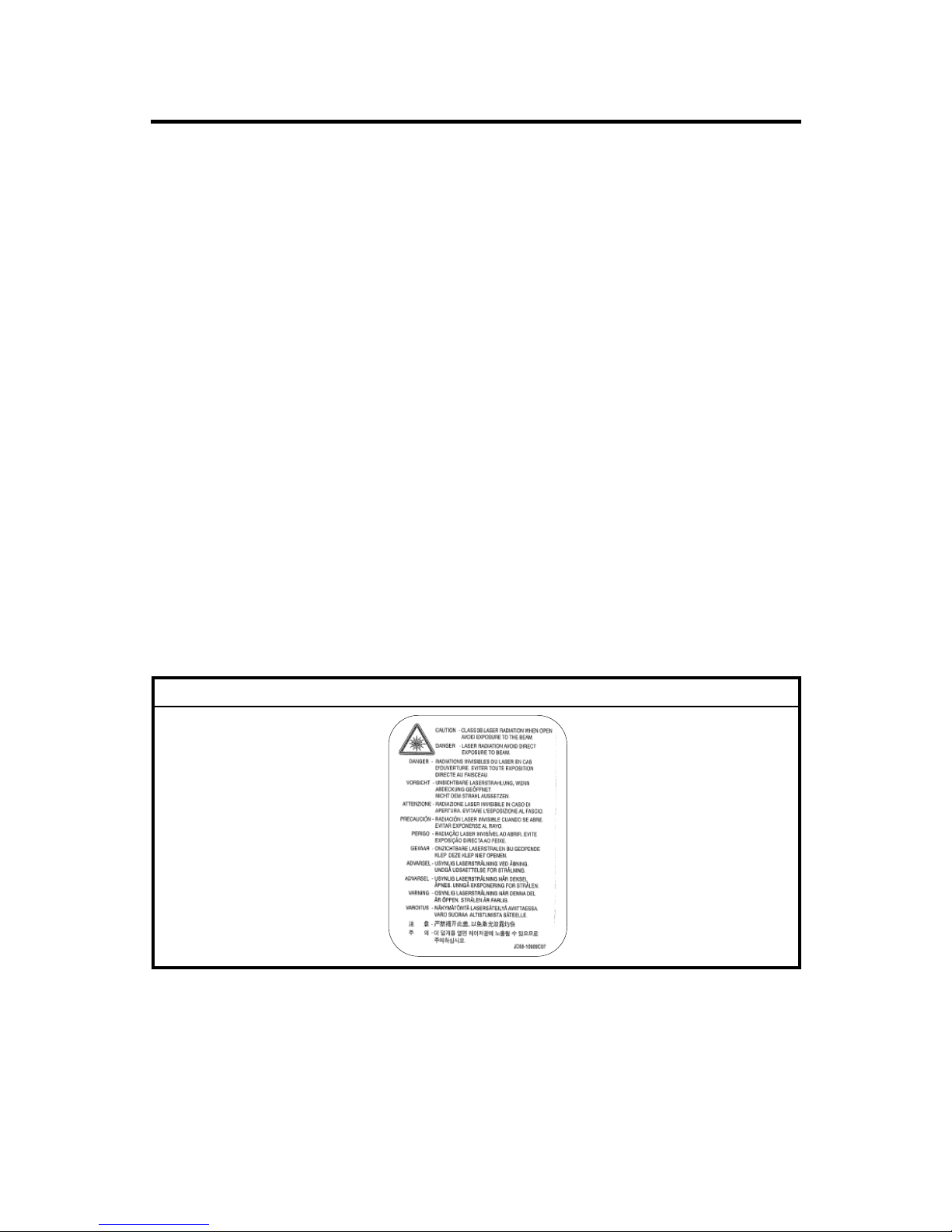
3. Laser Safety Statement: This machine is certified in the U.S. to conform to the
requirements of DHHS 21 CFR, chapter 1 Subchapter J for Class 1(1) laser
products and elsewhere. It is certified as a Class I laser product conforming to
the requirements of IEC 825. Class I laser products are not considered to be
hazardous. The laser system and printer are designed to prevent access to
laser radiation during normal operation, user maintenance, or prescribed
service activities.
Never operate or service the printer with the protective cover removed from
Laser/Scanner assembly. The reflected beam can damage your eyes.
When using this product, these basic safety precautions should always be
followed to reduce risk of fire, electric shock, and injury to persons.
WARNING

SAFETY PRECAUTIONS
TOXIC MATERIALS
This product contains toxic materials that could cause illness if ingested.
1. If the LCD control panel is damaged, it is possible for the liquid inside to leak
out. This liquid is toxic and contact with skin should be avoided. Wash any
splashes from eyes or skin immediately for 15 minutes under running water,
and contact a doctor. See a doctor immediately if the liquid gets into the mouth
or is swallowed.
2. Keep toner cartridges away from children. The toner powder contained in the
toner cartridge may be harmful if swallowed. Contact a doctor immediately if
toner powder is swallowed.
ELECTRIC SHOCK AND FIRE SAFETY PRECAUTIONS
Failure to adhere to the following instructions could cause electric shock or cause a
fire.
1. Use only the specified voltage to power this machine. Failure to do so could
damage the machine and cause a fire or electric shock.
2. Use only the power cable supplied with this machine. Use of an incorrectly
specified cable could cause the cable to overheat and potentially cause a fire.
3. Do not overload the power socket. This could lead to overheating of the cables
inside the wall and could lead to a fire.
4. Do not allow water or other liquids to spill into the machine. This can cause
electric shock. Do not let paper clips, pins, or other foreign objects fall into the
machine. These could cause a short circuit leading to an electric shock or fire
hazard. If foreign objects fall into the machine, power off the machine and
disconnect the power cord from the wall outlet immediately.
5. Never touch the plugs on either end of the power cable with wet hands. This
can cause electric shock.
6. Remove the power plug from the wall socket when servicing the printer.
7. Use caution when you insert or remove the power plug. The power plug must
be inserted completely. Otherwise, a poor contact could cause overheating and
lead to a fire. (When removing the power plug, grip the plug firmly and pull.)
8. Do not allow the power cable to become twisted or bent sharply around
corners. Do not place objects on top of the power cable. If the power cable is
damaged, it could overheat and cause a fire. Exposed cables could cause an
electric shock. Replace a damaged power cable immediately. Do not reuse or
repair a damaged cable. Additionally, some chemicals can attack the coating
on the power cable, weakening the cover or exposing cables causing fire and
shock risks.

9. Ensure that the power sockets and plugs are not cracked or broken in any way.
Repair such defects immediately. Take care not to cut or damage the power
cable or plugs when moving the machine.
10. Use caution during thunder or lightening storms. Disconnect the machine from
the power source when such weather conditions are expected. Do not touch
the machine or the power cord if it is still connected to the wall socket in these
weather conditions.
11. Avoid damp or dusty areas. Install the machine in a clean, well-ventilated
location. Do not position the machine near a humidifier. Dampness and dust
build-up inside the machine can lead to overheating and cause a fire.
12. Do not position the machine in direct sunlight. This will cause the temperature
inside the machine to rise, possibly leading to machine failure and, in extreme
conditions, could lead to a fire.
13. Do not insert metal objects into the machine through the ventilator fan or other
part of the casing. This could create contact with a high voltage conductor
inside the machine and cause an electric shock.
HANDLING PRECAUTIONS
The following instructions are for your own personal safety, to avoid injury and to
prevent damage to the machine.
1. Ensure that the machine is installed on a level surface, capable of supporting
its weight. Failure to do so could cause the machine to tip or fall.
2. Avoid placing fingers or hair in close proximity to any rollers, gears, or fans
within this machine while the machine is in operation.
3. Do not place any small metal objects, containers of water, chemicals, or other
liquids close to the machine. This can cause damage, shock, or fire if spilled
into the machine.
4. Do not install the machine in areas with high dust or moisture levels, beside
open windows, or close to a humidifier or heater.
5. Do not place candles, burning cigarettes, etc. on the machine. A fire may occur.
ASSEMBLY/DISASSEMBLY PRECAUTIONS
Replace with approved replacement parts only. Take care to note the exact
location of components and correct cable routing before you disassemble any part
of the machine. Ensure all parts and cables are replaced correctly. Perform the
following procedures before you disassemble the machine or replace any parts:
1. Check the contents of the machine
memory and make a note of any
user settings. These will be erased
if the main board or network card
is replaced.
2. Ensure that power is disconnected
before you service or replace any
electrical parts.
3. Disconnect interface cables and
power cables.
4. Use only approved spare parts.
Ensure that part number, product name,
voltages, current and/or temperature rating
are correct.
5. When removing or re-fitting any
parts, do not use excessive force
(especially when fitting screws into
plastic).
6. Take care not to drop any small
parts into the machine.
7. Handling of the OPC Drum:
• The OPC Drum can be
damaged if it is exposed to light.
• Take care not to expose the
OPC Drum to direct sunlight,
fluorescent, or incandescent
lighting. Exposure for as little as 5 minutes can damage the surface’s
photoconductive properties and will result in print quality degradation.
Remove the OPC Drum and store it in a black bag or other lightproof
container. Take care when working with the covers (especially the top cover),
as light can be admitted to the OPC area and can damage the OPC Drum.
• Take care not to scratch the green surface of OPC Drum. If the green
surface of the OPC Drum is scratched or touched, the print quality will be
compromised.
CAUTION1.TIF
Caution2.tif

ESD PRECAUTIONS
Certain semiconductor devices can be easily damaged by static electricity. Such
components are commonly called “Electro-statically Sensitive (ES) Devices”, or
ESDs. Examples of typical ESDs are: integrated circuits, some field-effect
transistors, and semiconductor “chip” components.
The techniques outlined below should be followed to help reduce the incidence of
component damage caused by static electricity.
CAUTION
Ensure that no power is applied to the chassis or circuit, and observe all
other safety precautions.
1. Immediately before handling a semiconductor component or semiconductorequipped assembly, drain any electrostatic charge on your body by touching a
known earth ground. Alternatively, employ a commercially available wrist strap
device, which for your personal safety should be removed prior to applying
power to the unit under test.
2. After removing an electrical assembly equipped with ESDs, place the assembly
on a conductive surface, such as aluminum or copper foil, or conductive foam,
to prevent electrostatic charge buildup in the vicinity of the assembly.
3. Use only a grounded-tip soldering iron to solder or desolder ESDs.
4. Use only an “anti-static” solder removal device. Some solder removal devices
not classified as “anti-static” can generate electrical charges sufficient to
damage ESDs.
5. Do not use Freon-propelled chemicals. When sprayed, these can generate
electrical charges sufficient to damage ESDs.
6. Do not remove a replacement ESD from its protective packaging until
immediately before installing it. Most replacement ESDs are packaged with all
leads shorted together by conductive foam, aluminum foil, or a comparable
conductive material.
7. Immediately before removing the protective material from the leads of a
replacement ESD, touch the protective material to the chassis or circuit
assembly into which the device will be installed.
8. Maintain continuous electrical contact between the ESD and the assembly into
which it will be installed, until the ESD or assembly is completely plugged or
soldered into the circuit.
9. Minimize bodily motions when handling unpackaged replacement ESDs.
Normal motions, such as the brushing together of clothing fabric and lifting
one’s foot from a carpeted floor, can generate static electricity sufficient to
damage an ESD.


INSTALLATION
PREVENTIVE MAINTENANCE
REPLACEMENT AND ADJUSTMENT
TROUBLESHOOTING
SERVICE PROGRAM MODE
DETAILED DESCRIPTIONS
SPECIFICATIONS
APPENDIX
TAB
POSITION 2
TAB
POSITION 1
TAB
POSITION 3
TAB
POSITION 4
TAB
POSITION 6
TAB
POSITION 5
TAB
POSITION 8
TAB
POSITION 7


INSTALLATION


INSTALLATION
SM 1-1 B273
Installation
1. INSTALLATION
Refer to the Operating Instructions for Installation procedures.

 Loading...