

Page 1

B230/B237
B230/B237
Course Reference Material
This presentation is the intellectual property of Ricoh University and may not be duplicate or distributed in any format.
Copyright © 2000-2005 Ricoh US Corporation. All Rights Reserved.
1
Page 2
B230/B230 TRAINING PROGRAM
2
2
Page 3

Introduction:
The B230/B237 is a mid-range network multi-functional color copier.
Based on the GW Architecture.
Provides:
Network Scanning (color originals can be scanned)
Local Storage (with the HDD)
Copying
Printing
3
Page 4

Objectives
The objectives of this training program is to:
• Understand installation, detailed descriptions, and routine
maintenance.
− Understand the PM table.
− Understan d the important SP codes.
• Understand troubleshooting and repair procedures of this
product as you would in the field.
4
ORIENTATION
Provide the trainees with information about the training course procedures,
facilities, objectives and rules.
Introduction of instructors
Introduce yourself to the class, and any other instructors who will be taking part.
Tell them who to talk to if they have any problems.
Introduction of trainees
Distribute a list of those attending the course.
Try to generate a friendly and relaxed atmosphere, and encourage the class to
get to know each other.
If it will help, have the trainees introduce themselves (name, company, work
experience).
Explanation of curriculum
Pass out copies of the training schedule
Impress the importance of getting to the class on time
Go over the course objectives (key points listed on the slide).
Explanation of training center rules
Explain the general rules of your training center (smoking, breaks, use of facilities,
etc.)
Explain the tools and equipment available at the facility.
Impress on the trainees that they should not touch the machines until the
instructor says so, and that they are responsible for replacing tools and keeping
the classroom in order.
4
Page 5

Course Overview
This presentation is the int e llectual property of Ricoh University and may not be duplicate or dist ributed in any format.
Copyright ©2000-2005 Ricoh US Corporation. All Rights Reserved.
The course is broken up into several modules. This section outlines these
modules.
The course covers the copier and the opt ional peripherals. Scanner, printer, fax,
and connectivity are not covered in this course.
5
Page 6

PRODUCT OUTLINE
The model will be introduced to the class.
The optional peripherals will be introduced to the class.
The product concept, sales points, and targets will be presented.
SPECIFICATIONS
The main specifications will be outlined. Significant items will be stressed.
Course Overview
Product Outline
Specifications
Installation
Machine Overview
Scanner
Image Processing
Laser Unit
PCU
Process Contr ol
6
MACHINE OVERVIEW
The components will be discussed.
The paper feed path and copying process will be outlined.
The machine's organization and overall PCB structure will also be covered.
SCANNER
The scanner mechanism will be discussed.
IMAGE PROCESSING
This section explains the image processing done inside this machine.
LASER UNIT
The laser diode circuits and laser optics will be described.
PCU
This section explains the components of the PCU.
All the image-creation processes around the drum, including development, are
covered in this section.
PROCESS CONTROL
This section explains the basic points about how the machine controls the copy
process to compensate for changes in operating conditions.
Toner supply control, and toner near-end/end detection are covered in this section.
6
Page 7

Toner Supply
Waste Toner Collection
Transfer and Separation
Paper Feed
Fusing
Paper Exit
Duplex
TONER SUPPLY
The toner supply mechanism will be described.
Toner supply control, and near-end/end detection are covered in the process
control section.
WASTE TONER COLLECTION
Waste toner collection will be discussed. There is no recycling.
TRANSFER & SEPARATION
Course Overview Continued
7
Image transfer, paper transfer, and paper separation will be described.
PAPER FEED
The paper feed mechanism for the main body will be described. The optional LCT
and tray units will be dealt with in later sections.
FUSING
Fusing will be described.
PAPER EXIT
The paper feed out mechanisms will be described.
DUPLEX
The duplex mechanisms will be described.
The duplex tray is a standard component of this model.
7
Page 8

OPTIONS
The options listed above will be described in the indicated order.
The only new one is the booklet finisher, and that contains mechanisms from the
V-C1 booklet finisher.
MAINTENANCE
PM is described briefly.
Course Overview Continued
Options
• ARDF
• Paper Tray Unit
• LCT
• Shift Tray
• One-bin Tray
• Bridge Unit
• 500-sheet finisher
• 1000-sheet finisher
• Booklet finisher
Maintenance
Troubleshooting
8
TROUBLESHOOTING
Basic points concerning service codes, diagnostics, and other troubleshooting
tools will be covered.
8
Page 9

Product Overview
This presentation is the int e llectual property of Ricoh University and may not be duplicate or dist ributed in any format.
Copyright ©2000-2005 Ricoh US Corporation. All Rights Reserved.
The course is broken up into several modules. This section outlines these
modules.
The course covers the B230/B237 and the optional peripherals. Scanner, printer,
and network software are not covered in this course.
9
Page 10
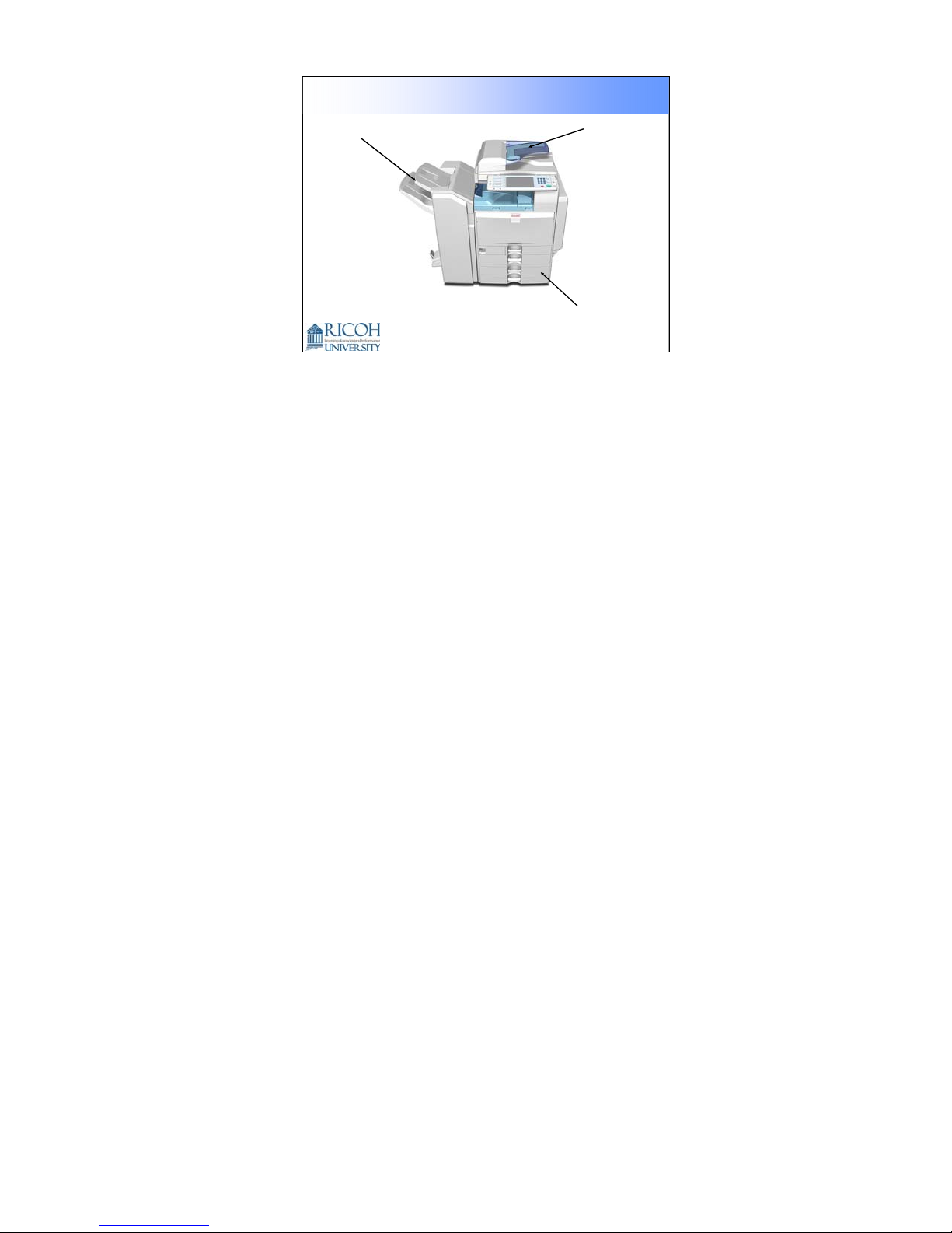
Appearance
Booklet
Finisher
ADF
Two-tray
Paper Tray Unit
10
Here is a view of the machine with three optional peripherals installed.
There are other options, as we will see later.
10
Page 11
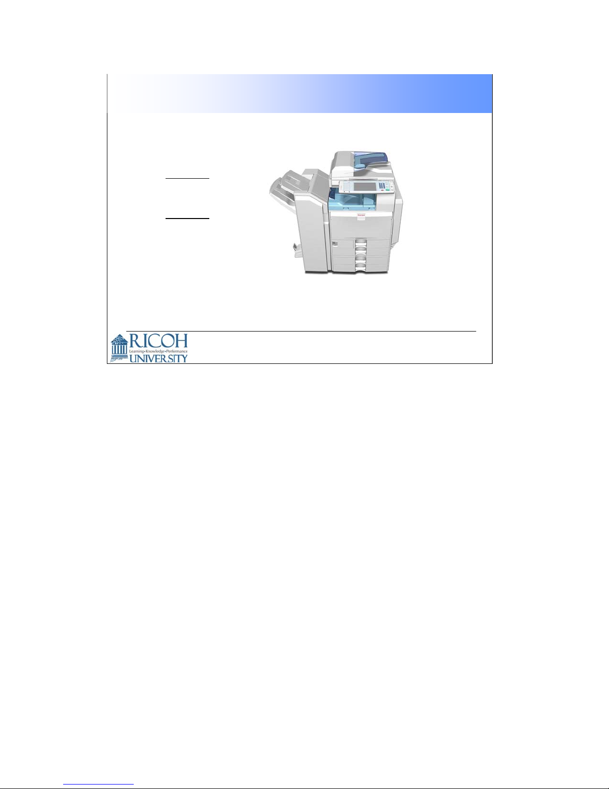
B230:
• 25 cpm
B237:
• 30 cpm
Models in this line
11
11
Page 12
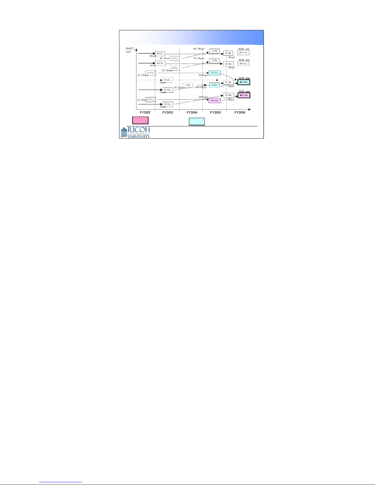
Product Positioning
= B230
AT-C1a
AT-C1b
= B237
12
This chart shows which machines the B230/B237- could be used as alternatives
or as replacements.
The faster machine could be seen as a replacement for the slower models of the
Jupiter-C1/C2 series. The B230/B237 uses a four-PCU tandem color copying
system, like the Jupiter, so it is quite fast.
12
Page 13
SALES POINTS
This presentation is the intellectual property of Ricoh University and may not be duplicate or distributed in any format.
Copyright © 2000-2005 Ricoh US Corporation. All Rights Reserved.
13
Page 14

Main Sales Points
High performance (near black-and-white model performance)
• Short Warm Up time: 45 sec.
• Shorter First Copy Output Time:
− Black-and-white 6.7 sec
− Full color: 9.7 sec
Productivity
• High speed color output
− B230: 25 cpm, B237: 30 cpm
• Booklet Finisher
• Large Paper Capacity: Max. 3,100 sheets
• LCT can be refilled during copying
• High Speed Scanning: 50 pages/minute (monochrome or color, LT
LEF, 600dpi)
• Thick paper (up to 216 g/m
2
) can be fed from the front tray
14
There are also a lot of connectivity features, which we will not explain in this class.
We will limit ourselves to the engine in this course.
14
Page 15

Color Mode
Icon
New Display Panel
Check Modes
Job List Remaining Job Time
15
The color mode icon changes when you select Auto color Select, Full color, or
Black and White. Ask the class to try it on the machine, if you have one set up
already.
Other modes, such as two-color mode, can also be shown as options on
the display by adjusting machine settings.
The Check Modes button is part of the LCD display.
The Job List button is a new feature.
You can also see an estimate of the remaining time for the job, at the bottom of
the screen. (Does not work for fax communication.)
15
Page 16

Animated Guidance Display
16
For some functions, such as removing jams and replacing toner, an animated
guidance appears on the screen.
16
Page 17
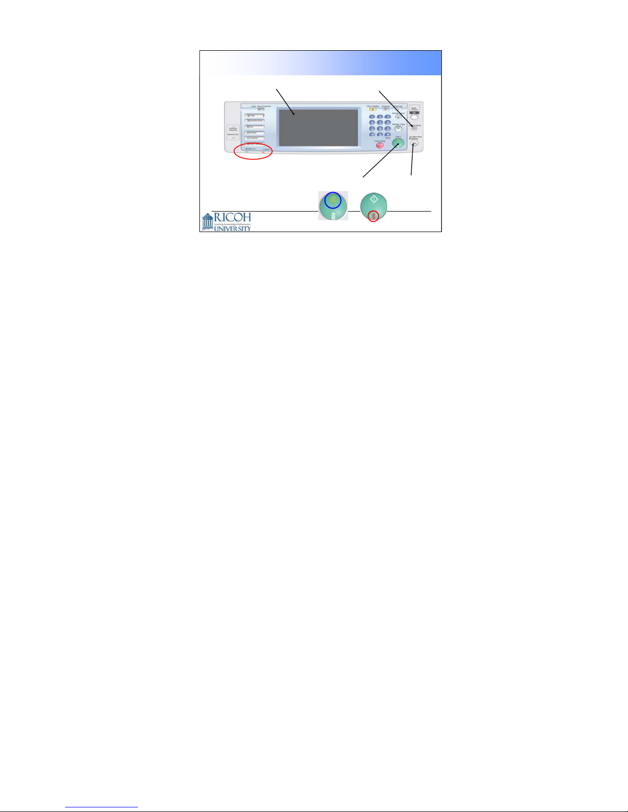
Improved Operation Panel Layout
Larger LCD
Login/Logout,
for Authentication
Status Lamps
Can be seen from a distance
Start Key
Simplifies
the Display
17
The login/logout button makes authentication a bit easier.
The ‘simplified display’ button reduces the amount of information on the LCD
panel. The next slide gives an example.
The red and green lamps on the Start key show clearly when the machine will or
will not start.
17
Page 18
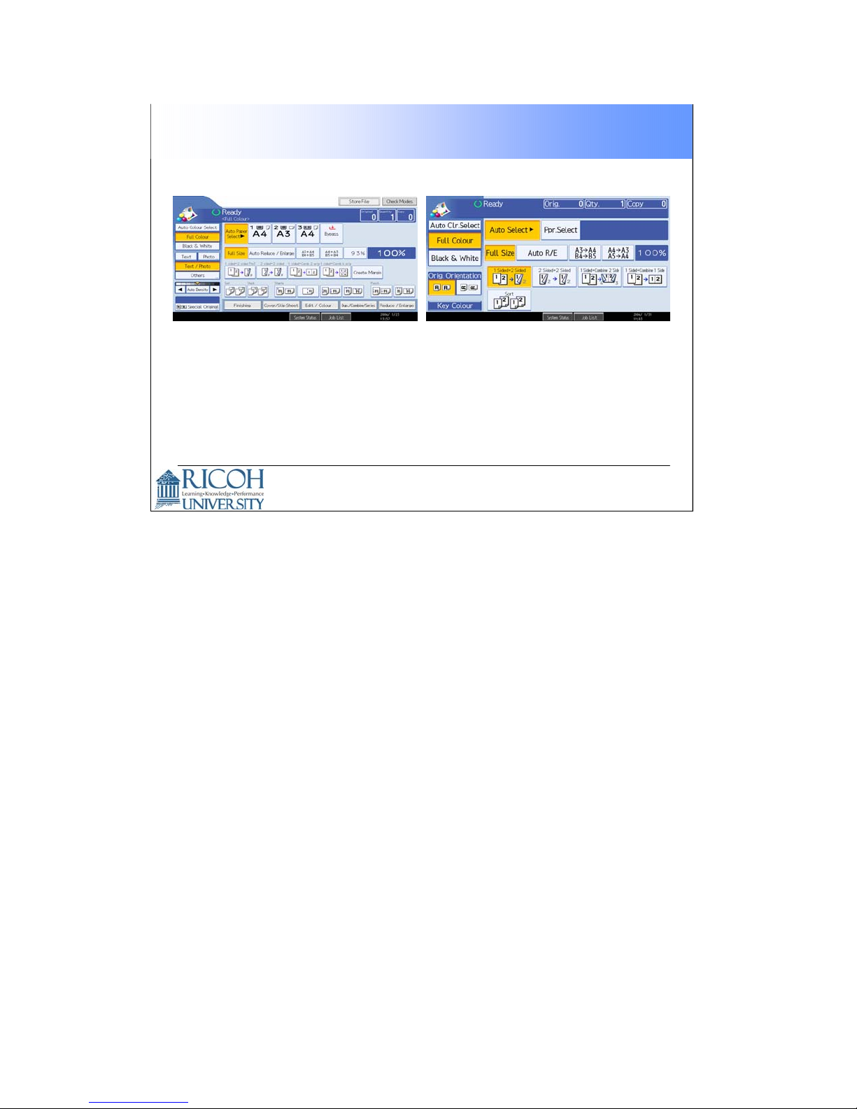
Simplified Display
Normal Display Simplified Display
The simplified display appears when you push the
Simplified Display button.
18
18
Page 19
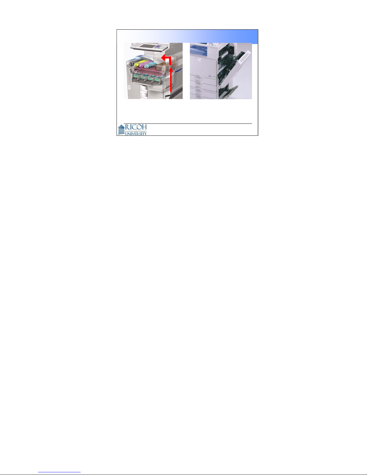
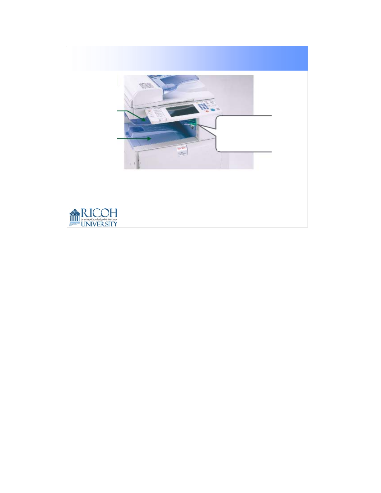
Easy Jam Removal
Simple paper path
All jams can be removed from the right side of the
machine.
If the finisher is installed, jams can occ ur in the finisher.
•
19
The photo on the left shows that the path through the machine is simple.
19
Page 20
LED indication on the One-bin Tray
One-bin
Tray
Standard
Output Tray
This LED lights when an output arrives on the one-bin tray.
The one-bin tray is an optional device.
•
If the one-bin tray is set up to receive fax messages, then
the LED tells the customer when a fax message has been
printed.
This LED lights
when the one-bin
tray has paper in
it
20
20
Page 21
Paper Tray Handle
The handle allows the paper tray to be pulled easily with an
‘overhand’ or ‘underhand’ grip.
21
21
Page 22
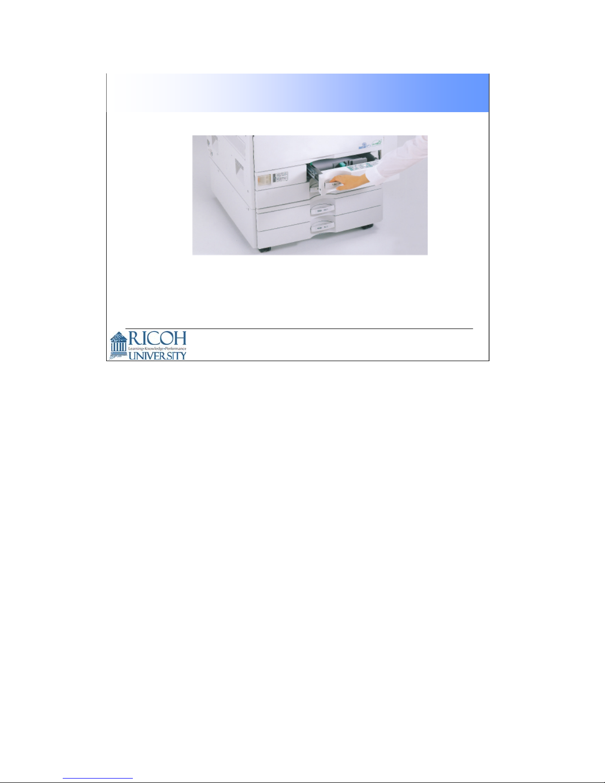
Replacing Toner is Easy
Toner cartridges can be changed with one hand, and with
one easy movement.
22
22
Page 23

ARDF Accessibility
To make the machine
accessible to people in
wheelchairs, the
components operated by a
users must be in the red
area as shown in the
diagram.
USA regulations
•
The ref ore, the lifting angle
of the ARDF must be
limited to within 40
degrees.
See the next slide for the next part of this story.
23
23
Page 24
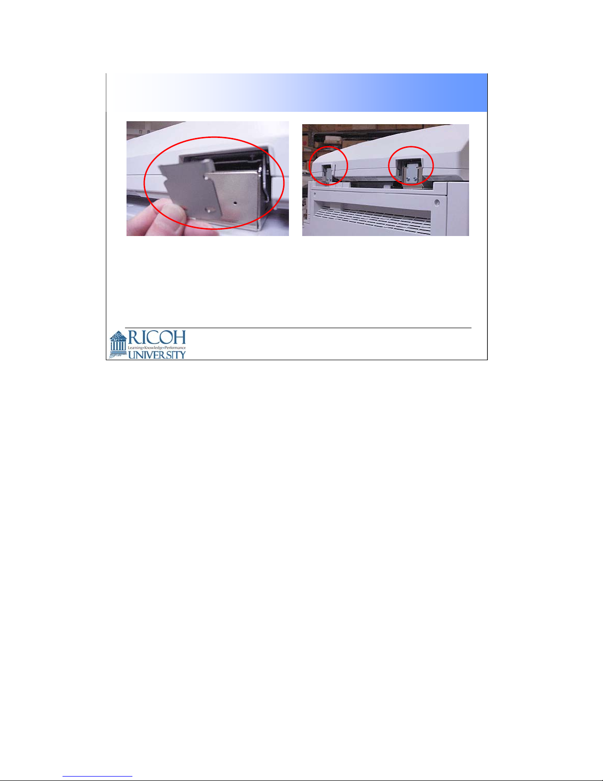
ARDF Accessibility Continued
To limit the ADRF angle, these hinges will be available as
options or service parts.
24
24
Page 25

Mainframe with No Options
Duplex
Bypass tray
2x500-sheet trays
500-sheet output tray
8.5-inch W-VGA touch
panel
Printer/Scanner
1024MB Memory
40GB HDD
PCL5c/6, RPCS
10/100 BaseTX
USB2.0
This slide shows what you get with the base machine.
Note that the printer/scanner is standard.
25
25
Page 26
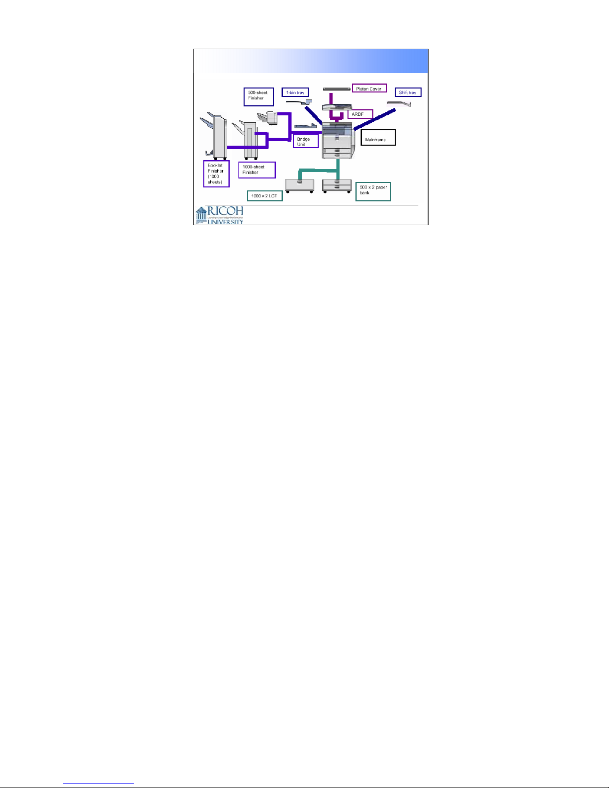
Paper Handling Options
26
You can install up the following:
The platen cover or the ARDF
Shift tray or one of the three finishers (a finisher requires the bridge unit)
One-bin tray
The two-tray paper feed unit (also called a ‘paper bank’) or the LCT
Except for the booklet finisher, all the above items are the same as those used
with the B156, but with a different color for the cover.
The booklet finisher is a new item. The booklet mechanism is the same as in the
Euphrates booklet finisher for the B200.
The platen cover is like the one that is used with J-P2+CFE, J-C1 , B202 series.
The platen cover, two-tray feed unit, LCT, and bridge unit will also be used with
the AP-C1.
26
Page 27

Fax Options
Fax Option: New Item
Optional G3 unit: New Item
SAF memory (32MB): Same as B202 series/B156
Handset: Same as B202 series/B156
Fax Stamp Ink: Same as B079/B082, B202 series
27
27
Page 28

Printer/Scanner Options
PostScript3 option: New Item
Required to use the PDF Direct Print Function
•
Wireless LAN (IEEE 802.11b): Same as B202 series, B156
IEEE 1284: Same as B202 series, B156
IEEE 1394: Same as B202 series, B156
Bluetooth: Same as K-C2.5, PG-C1, MT-C3, B-C3, AP-C1
USB Host: New, also used with PG-C1, MT-C3, B-C3
Required to attach IC card or PictBridge
•
Media Link Board: New, also used with PG-C1, MT-C3, B-
C3
Video Link Board : New, also used with MT-C3, B-C3
Required to connect the Fiery controller
•
PictBridge: New
Enables direct printing from a digital camera
•
28
28
Page 29
Security Options
HDD Data Overwrite Security Unit: Also used with
B202 series, B156
Copy Data Security Unit: Also used with
B079/B082, R-C4
29
29
Page 30

Other Options
Java VM Card: New Item, also used with MT-C3,
B-C3
Web Browser Option (SDK): New Item
Optional counter Interface: New Item
• This is a 20-pin interface. It is required when you attach a
key counter.
Key Counter Bracket: Also used with B202 series
30
30
Page 31

Reliability Targets
Unit life (2 prints per job): 1200K or 5 years
Average Copy Volume per month (copy + fax +
print):
• B230: 5K
• B237: 8K
Max Copy Volume per month: 20K (Target Color
Ratio: 30%)
PM cycle: 80K (Target Color Ratio: 30%)
31
31
Page 32

Yield Targets
Toner
• Cartridge Capacity
− Black: 450g /cartridge
− Cyan / Magenta / Yellow: 360g /cartridge
• Target Yield (LT, 5% coverage)
− Black: 20K outputs /cartridge
− Cyan / Magenta / Yellow: 15K outputs /cartridge
Staples
• 5,000 staples per cartridge (all finishers)
32
The toner bottles are not compatible with other products.
The staple refill cartridges are compatible with those used in the U-C1, B156, and
B202 series.
The set staple cartridges are also compatible for the above models, except for the
booklet finisher. The cartridge for that finisher is not compatible.
32
Page 33

Specifications
This presentation is the intellectual property of Ricoh University and may not be duplicate or distributed in any format.
Copyright ©2000-2005 Ricoh US Corporation. All Rights Reserved.
.
33
Page 34

Original scanning:
Development:
Copy/Print Resolution:
Mainframe
Desk Top Configuration:
One-dimensional solid scanning
through CCD
Dry electrostatic transfer system Copy process:
Dry two-component magnetic brush
development system
Belt pressure system Fusing:
Sheet / Book / Object Original Type:
Max: 11”x17”(DLT) / A3 Original Size:
Less than 30mm (Less than 5kg) Thickness of Original:
600dpi / 256gradations Scan Resolution:
Copy: 600dpi /4bit,
Print: 600dpi/4bit, 2bit, 1bit
12”x18” / 297x432mm Max Printable Area:
34
34
Page 35

Mainframe
Paper Weight:
Copy Speed B230
(ARDF 1to1)
B237
(Simplex to duplex)
st
(LT/A4 LEF/from 1
tray)
Standard Tray: 16-57lbs / 60-216 g/m
Bypass Tray: 16-57lbs / 60-216 g/m
Paper Bank: 16-67lbs / 60-253 g/m
Duplex Unit: 17 to 45lbs / 64 to 169 g/m
2
2
2
2
FC: 25cpm / BW: 25cpm (LT/A4 LEF)
OHP/Thick Paper(over105gsm): 16cpm (LT/A4 LEF,
FC/BW)
FC: 30cpm / BW: 30cpm (LT/A4 LEF)
OHP/Thick Paper(over105gsm): 16cpm (LT/A4 LEF,
FC/BW)
FC: 23cpm /BW: 23cpm(LT/A4 LEF) Copying Speed B230
FC: 28cpm /BW:28cpm(LT/A4 LEF) B237
FC:9.7sec. / BW: 6.7sec. 1stCopy Time :
Less than 45sec. Warm-up Time:
35
35
Page 36

Mainframe
US model: 120V 60Hz Power Source:
Max. Power Consumption:
Machine Dimensions:
(Width x Depth x Height)
Counter:
US model: 1,440W
EU/Asia model: 1,500W (Full Configuration)
650 x 654 x 740mm (Standard)
670 x 698 x 1,000mm (with 2-Tray Paper
Bank)
Less than 120kg (with ARDF) Machine Weight:
US model:
Electronic counter & optional mechanical
counter
Other models:
Electronic counter
36
36
Page 37

Thick Paper Productivity
Mode
Thin Paper
Plain Paper
Middle Thick
Paper
Thickness
2
(g/m
)
52-59
-81
-105
BK CPM
25
25
25
FC CPM Model
25B230
25
25
1616-169Thick Paper 1
1616-219Thick Paper 2
16 16 -253Thick Paper 3
303052-59Thin Paper B237
3030-81Plain Paper
3030-105Middle Thick
1616-169Thick Paper 1
1616-219Thick Paper 2
1616-253Thick Paper 3
37
37
Page 38

Resolution
Fonts
Host Interface
Std.
Std.
Std.
Option
Max.
Std.
Option
Std.
Option
Printer
General Specification
RM7035C-600MHz CPU
1024MB (DDR SDRAM-DIMM(PC-2100)) RAM
40GB Hard Disk Drive
RPCS, PCL5c, PCL6 PDL
Adobe PostScript3
600 x 600 dpi / 4bit
(= 2400 dpi equivalent x 600 dpi )
PCL: 46 fonts (Truetype: 10 fonts, Intell: 35
fonts, Bitmapped: 1 font) + International fonts:
13 Intellifonts
PS3 : 136 Roman fonts
Ethernet (RJ-45 network port : 10Base-
T/100Base-TX), USB2.0
USB Host I/F(PictBridge), IEEE1284/ECP,
IEEE1394,
Wireless LAN (IEEE802.11b, WPA support),
Bluetooth
38
38
Page 39

Printer
General Specification
Network Protocol
MIB support
Network/Operating
Systems
TCP/IP (IP v4, IP v6), IPX/SPX, SMB, Apple Talk
(Auto Switching)
Standard MIB (SMNP Printer MIB):
MIB-II(RFC1213), HostResource(RFC1514),
PrinterMib(RFC1759)
Private MIB: Ricoh Original
Windows 95/98SE/NT4.0/2000/Me/XP/Server 2003
Netware 3.12, 3.2, 4.1, 4.11, 5.0, 5.1, 6, 6.5
Unix; Sun Solaris, HP-UX, SCO OpenServer,
RedHat Linux, IBM AIX
Mac OS 8.6-9.2x, OS X 10.1 or later
SAP R/3, NDPS Gateway
IBM iSeries/ AS/400-using OS/400 Host Print
Transform
39
39
Page 40

Scanner
General Specification
Resolution:
Scan Speed:
Network Interface:
Protocol:
Compression
Method:
100 / 200 / 300 / 400 / 600/1200* dpi
Default = 200dpi *only BW TWAIN
BW: 50pages/minute (A4/LET LEF / 200dpi )
FC: 50pages/minute (A4/LET LEF / 200dpi)
Main Scan: 297mm, Sub Scan: 432mm Scan Area:
Option (With Optional File Format Converter) sRGB Support:
Ethernet 10/100BaseTX, IEEE 1394/IP over,
Wireless LAN(802.11b)
Network: TCP/IP
Sending E-mail: SMTP, POP3
Scan to Folder: SMB, FTP, NCP
BW: TIFF (MH, MR, MMR)
Grayscale, Full color: JPEG
40
40
Page 41

Scanner
General Specification
Scan Mode:
Image Density :
Standard:
BW Text, BW OCR, BW Text/Photo, BW Photo,
BW Grayscale, FC Photo, FC Text
Optional:
ACS (With Optional File Format Converter)
Auto Density Selection (Effective only in BW and
Grayscale scan mode)
Manual: 7 levels (Effective in BW/Grayscale and
FC scan mode)
YesImage Rotation:
Yes (Default = SADF)SADF / Batch Mode:
YesMixed Size Mode:
41
41
Page 42

Products Comparison
B230/B237 B156 B202/B178
Configuration Desk Top Desk Top Desk Top
Dimension
(W x D x H)
Weight 120kg 85kg 120kg
Scan Resolution 600x600dpi 600x600dpi 600dpi
Copy/Print Resolution
(dpi)
Max Print Paper Size 12”x18” 12”x18” 12”x18”
Paper Weight 52-253g/m
Paper
Feeding
Capacity
(80g/m
2
)
Std 1100sheets 500sheets 1,100sheets
Max. 3,100sheets 2,600sheets 3,100sheets
650 x 654x 740
mm
Copy:600x600
Print:600x600
(4bit)
2
550 x 682 x
781mm
Copy:600x600
Print:600x600
(2bit)
64-163g/m
17-43 lbs
2
670 x 698 x
859mm
Copy: 600x600
Print:1200x1200
600x600 (2bit)
60-163g/m
16-43 lbs
2
42
42
Page 43

Products Comparison
B230/b B156 B202/B178
Copy Speed
(A4/LT LEF)
1stCopy Speed BW 6.7sec.
Warm-up Time 45sec. 99sec. 99sec.
Multiple Copy 1-999 1 – 100 1 – 999
Duplex Standard Option *2 Standard
HDD Std. 40GB 40GB 80GB
Max. 40GB 40GB 80GB
Memory Std. 1,024MB 768MB 1,024MB
Max. 1,024MB 768MB 1,024MB
Booklet Finisher Yes No Yes
BW: 25/30cpm
FC: 25/30cpm
FC 9.7sec.
BW: 24/32cpm
FC: 10cpm
BW 7.8sec.
FC18.0sec.
BW: 28/35cpm
FC : 24/28cpm
BW 8.0sec.
FC10.0sec.
43
43
Page 44

Installation
This presentation is the intellectual property of Ricoh University and may not be duplicate or distributed in any format.
Copyright ©2000-2005 R icoh US Corporation. All Rights Reserved.
44
Page 45

Verify the following before installing the machine
and all its options:
Environment
Machine Level
Space Requirements
Power Requirements
Requirements:
Environment:
Installation Requirements
45
1. Temperature range: 10 degrees C to 32 degrees C (50 to 89.6F)
2. Humidity Range: 15% to 80% RH
3. Ambient Illumination: Less than 1500 lux
4. Ventilation: 3 times/hr/person or more
5. Do not install the machine in areas that are exposed to corrosive gas.
6. Install the machine at locations lower than 8,200 ft. above sea level
7. Install the machine on a strong, level base (no more than 5 mm inclination on
any side
Machine level:
Front to back: within 5mm or .2”
Right to left: within 5mm or .2”
Space Requirements (minimum):
Front: 30”
Back 3.9”
Left 3.9”
Right 20”
45
Page 46

Important Safety Notices
Observe all electrical safety standards
46
Power Requirements:
Input Voltage level: 120V, 60Hz. More than 12 Amps
Permissible voltage fluctuations:
+/-10%
46
Page 47

Optional Unit Combinations
Machine Options
47
47
Page 48

Optional Unit Combinations
Controller Options
48
48
Page 49

Installation Sequence
Be sure to follow the installation flowchart in the service manual.
49
49
Page 50

Accessory Check
Check the contents of all boxes thoroughly
Check the quantity and condition of the
accessory list
50
50
Page 51

Inside the Front Door
51
51
Page 52

Installation Steps
Remove the screw that locks the drum
positioning plate lever
Open the drum positioning plate
52
52
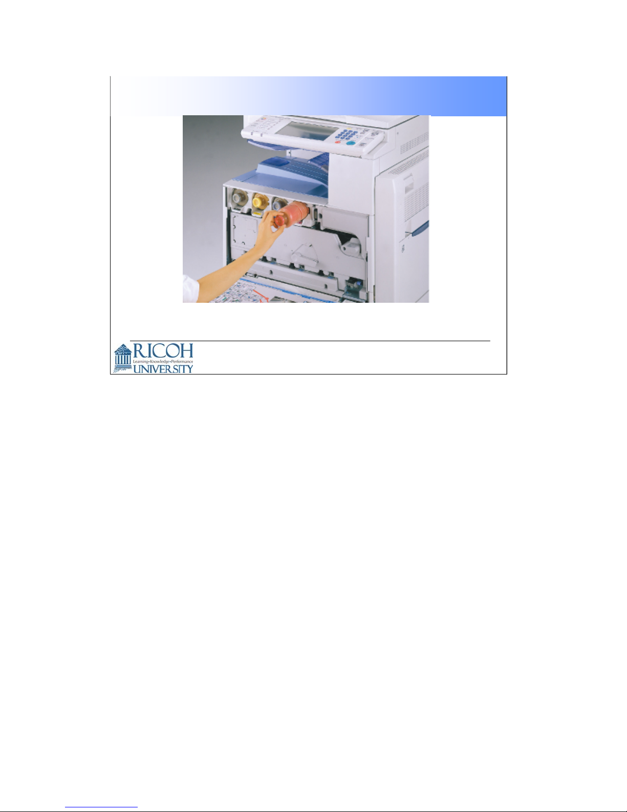
Page 53

Installation Steps
Installing and removing toner bottles
53
53
Page 54

Installation Steps
4 color PCUs/Dev Units
Installing and removing
PCUs/Dev Units
54
54
Page 55

After Installation
Plug in the power cord and turn on the main
switch
Obtain a color original and verify the operation of
the machine and all it’s options and accessories
Enter the User Tools mode and print a
Configuration page. Make sure all installed
options and accessories are listed in the ‘System
Reference” section of the Configuration Page
55
55
Page 56

Machine Overview
This presentation is the intellectual property of Ricoh University and may not be duplicate or distributed in any format.
Copyright © 2000-2005 Ricoh US Corporation. All Rights Reserved.
56
Page 57

1. Scanner HP sensor
2. ADF exposure glass
nd
3. 2
scanner (2ndcarriage)
Component Layout
Refer to Section 6.1.1 SM
57
4. Exposure glass
5. Original width sensor
6. Scanner Lamp
7. 1stscanner (1stcarriage)
8. Original length sensor
9. Lens Block
10.Sensor board unit (SBU)
11.Scanner motor
12.Fusing unit
13.Duplex unit
14.Paper transfer unit
15.Registration roller
16.By-pass feed table
17.Tray 2
18.Tray 1
19.Toner collection bottle
20.Laser optics housing unit
21.PCU (4 colors)
22.Image transfer Belt Cleaning Unit
23.Image Transfer Belt Unit
24.Toner bottles (4 colors)
25.Toner ID sensor
57
Page 58

Machine Details
Laser optics unit
• There are four lasers, and four sets of optics. One for
each color toner (KYCM). Each polygon mirror reflects
light from two LD units.
PCU
• There are four PCU units, one for each color toner. It
includes the drum unit and development unit.
Toner cartridges
• Toner is supplied from the cartridges to the development
units by a toner supply pump.
58
58
Page 59

Machine Details continued
Image transfer unit
• Bias rollers located opposite the OPC drums transfer
toner from the drums to the transfer belt. Four toner
images are super-imposed onto the belt.
Paper transfer roller unit
• The ITB drive roller pushes the toner from the transfer
belt to the paper (the transfer roller is an idle roller).
Fusing unit
• This is a belt-type fusing unit. A heating roller, not in the
paper feed path, heats a belt. Then the belt in turn, heats
the hot roller. This type of unit warms up the rollers faster
than a conventional two-roller system.
59
59
Page 60

1. Original tray
Paper Path
2. Original exit tray
3. Duplex inverter
4. Duplex feed
5. By-pass tray feed
6. Tray 1 feed
7. Tray 2 feed
8. Tray 3: Optional paper feed unit/LCT
9. Tray 4: Optional paper feed unit
10. Finisher stapler (Optional)
11. Finisher punch (Optional)
12. Finisher lower tray (Optional)
13. Finisher proof tray (Optional)
14. Inner Tray
Refer to Section 6.1.2 SM
60
60
Page 61

Drive Layout
Rear View
Refer to Section 6.1.3 SM
61
1. Scanner motor: Drives the scanner unit.
2. Drum drive motor-CMY: Drives the drums for magenta, cyan, and yellow.
3. ITB (Image Transfer Belt) contact motor:
Moves the ITB into contact and away from the color PCUs.
4. Toner transport motor: Drives the toner attraction pumps and the toner collection coils
from the PCUs, from the transfer belt unit, and inside the toner collection bottle. Also
rotates the toner bottles.
5. Development drive motor-CMY:
Drives the color development units (magenta/cyan/yellow).
6. Development clutch-K Turns on/off the drive power to the development unit-K.
7. Paper feed clutch Switches the drive power between the tray 1 and tray 2.
8. Paper feed motor: Drives the paper feed mechanisms (tray 1/tray 2/by-pass tray).
9. Drum/Development drive motor-K:
Drives the black drum and development unit.
10. Registration motor: Drives the registration roller.
11. Paper transfer contact motor Moves the paper transfer roller in contact with the transfer
belt.
12. ITB drive motor: Drives the transfer belt unit.
13. Fusing/paper exit motor: Drives the fusing unit and paper exit section.
61
Page 62

Board Structure
BICU (Base Engine Control Unit):
62
The BICU controls all the mechanical components. The BICU has six CPUs. The
CPUs control the following functions:
• Engine sequence
• Engine operation
• Polygon motor control
• Image processing
Controller:
The controller connects to the BICU through a PCI bus. The controller handles the
following functions:
• Machine-to-host interface
• Operation panel interface
• Network interface
• Interfacing and control of the optional IEEE1284, Bluetooth, IEEE1394,
IEEE802.11b (wireless LAN), USB Host, HDD, and DRAM DIMM
LD Drive Board:
This is the laser diode drive circuit board.
SBU:
The Sensor Board Unit has a CCD (cha rge-coupled device) and an analog-to digital
conversion circuit.
Operation Panel Board:
Controls the display panel, the LED and the keypad.
Scanner I/O Board (SIO):
The scanner I/O board is a circuit board that transmits control signals, image data,
and electricity.
I/O Board (IOB)
Contains drivers for motors and other mechanical components.
Motherboard:
Connects the FCU board to the BICU. This board i s supplied with the optional fax
unit.
FCU:
The FCU (fax controller unit) controls the fax programs and communicates with the
controller to share copier resources.
62
Page 63

Transfer
Belt
OPC
Drum
Printing Process
ITB Drive roller
Laser Optics Housing Unit
Transfer roller
63
1. A latent image is written to each OPC drum by the laser unit. There are 4 separate laser
beams, one for each color drum.
2. Each drum is charged with a negative charge using a charge roller.
3. When the laser beam hits the drum, it neutralizes the charge in the area where the beam
strikes the drum, creating a latent image.
4. Negatively charged toner (one color for each drum) is attracted to the discharged areas of
the drum (latent image) and develops a toner image on each drum.
5. The developed toner image (on each drum) is then transferred to the Image Transfer Belt
(ITB) to create a full color image on the surface of the ITB.
6. The full color image is again transferred from the surface of the ITB to a passing sheet of
paper. The image on the sheet of paper is then sent to the fusing unit to fuse the image
permanently to the paper.
63
Page 64

SCANNER
This presentation is the intellectual property of Ricoh University and may not be duplicate or distributed in any format.
Copyright ©2000-2005 Ricoh US Corporation. All Rights Reserved.
In this section, the mechanical components of the scanner will be described.
The optional ADF is described in a separate section.
64
Page 65

Optical Path
ADF Exposure
Glass
One exposure lamp
600 dpi color CCD
Anti-condensation heater is optional
No adjustments required in the field for the CCD and lens
block
Main Exposure
Glass
Exposure
Lamp
CCD
65
Outline the optical path.
In platen mode, the original is fed to the main exposure glass, and the scanner moves
down the original during scanning.
In ADF mode, the scanner stays at the home position, and the original is fed past the
ADF exposure glass.
The optics anti-condensation heater is an option. It prevents condensation on the
mirrors, which will cause image problems.
65
Page 66

Scanner Drive
Scanner Motor
Motor and wire drive mechanism
The same motor drives the first and second scanners.
The first scanner contains the exposure lamp, reflectors, the 1st mirror, and the
lamp regulator. The second scanner contains the 2nd and 3rd mirrors.
The regulator is mounted on the scanner to reduce the wiring between the lamp
and the regulator.
66
The second scanner moves at half the speed of the first scanner. This is to
maintain the focal distance between lens and original.
In this machine, wires are used instead of timing belts. These are more difficult to
replace, but copy quality is better (less jitter).
Note that the operation in ADF mode is different from platen mode (as shown on the
previous page).
The service manual explains how the motor speed and image processing control the
magnification.
66
Page 67

APS sensors.
There are two width sensors and three length sensors. The service manual
shows where these sensors are located.
The CPU checks the sensors when the platen cover sensor detects that the
cover is being closed.
Original Size Detection
Platen Cover
Sensor
Reflective photosensors detect the size.
67
If the cover stays open during copying, the CPU checks the sensors when the
Start key is pressed.
Make sure that you are familiar with the table of sensor output vs original size.
Make sure that you understand what happens when all sensors are off (such as when
A5 sideways is set - too small for the sensors to detect).
Use SP 4-303 this to select the machine’s behaviour if the sensors cannot
detect the size.
Use SP 5126 to control the size that is detected for the ‘F’ sizes, which are very similar
(8½ x" 13", 8¼" x 13", 8" x 13").
67
Page 68

Image Processing
This presentation is the intellectual property of Ricoh University and may not be duplicate or distributed in any format.
Copyright © 2000-2005 Ricoh US Corporation. All Rights Reserved.
68
Page 69

How the Image is Processed
The CCD (Charged Coupled Device) generates
three analog video signals.
The SBU (Sensor Board Unit) converts the
three analog signals to 10-bit digital signals. It
then sends these signals to the IPU (Image
Processing Unit).
The IPU processes the image. Then the image
data (4 bits/pixel) is sent to the controller.
69
69
Page 70

Overview
Operation Panel
LCD
8.5inch
SBU
CCD
Xenon
Lamp
INV
SIO
APS
AKS
CPU
RM7035
DDR
Securit y Unit
LVDS
CPU Path
SDR AM
Controller
ASIC
FM
Taurus
ASIC
Orion
CPU
eSOC
CPU
FLOC
ASIC
GASBU
AFE
Copy Dat a
BiCU
Scanner
STM
IOB
STM
STM
Driver
Opt iona
l Units
ARDF
HP Sens or
SOL&CL
Driver
Driver
Finisher
BANK/LCT
Shift Tray
Bridge Unit
ASIC
Trumpet
LOCAL P CI
ASIC
Shaker
RAPI6 4
ASIC
ASIC
Lupus
Strix
ASIC
GAVD
Type-W
FROM
SRAM
4MByte
512kByte
ASIC
ASIC
TRIO2
TRIO2
MT
CL&
Sensor
H.V. P. P
SOL
HDD
RiO3
Option
M ax.:3 Slot s
RAPI6 4
+5V, + 5VE, +12V, +24V
・to BiCU
AC Drive
Heater
FU sing
TH&Th.Pile
M o th e r B o ard
LDB
ASIC
PMAC- A
MT
PSU
・to IOB
・to SIO
G3
CCUIF
FCUIF
FCU
Expansion
S ynchronizing
Detection
MLB
Image
Data
CPU
Path
PCI
Path
70
70
Page 71

Signal processing
A/D conversion
White level correction
Black level correction
Others
More about the SBU
You need to adjust the following after you replace the SBU:
SP 4008. Scanner sub-scan magnification
How the SBU Processes the Signal
Signal Amplification
•
• Signal Composition
•
The SBU controller exchanges the R and B signals if the original
is scanned with the ARDF.
• The properties of the scanner unit, (necessary for controlling the
scanner VPU (video processing unit)), are stored in the NVRAM
on the controller.
• SBU test mode
71
SP 4010. Scanner leading edge registration
SP 4011. Scanner side-to-side registration
Output the VPU test pattern with SP 4907 to make sure the scanner VPU control
functions correctly. Look in the troubleshooting section if you need more details.
71
Page 72

What happens in the IPU?
Shading correction
Picture element (Dot Position) correction
Scan line correction
Image separation
Auto color select
Scanner gamma correction
Filtering
Auto Image Density Selection
Color conversion
Main scan magnification
Printer gamma correction
IPU test mode
72
72
Page 73

Printer Gamma Correction
K
The gamma curves for C, M, Y, and K are not equal.
If this causes copy quality problems, the user can do the ACC
procedure.
73
A gamma curve describes the relation between the image density of the original
and that of the copy. The relationship is not linear: doubling the ID of an original
does not double the ID of the copy.
The printer characteristics are much more variable than the scanner. Therefore,
the printer gamma needs recalibration and adjustment from time to time. This is
done using the ACC procedure.
Each color has separate gamma curves for photo mode and letter mode, and for
copier mode and printer mode.
The gamma curves for C, M, Y, and Bk toner should be identical, but they are not.
ACC (Auto color Calibration) can be used to correct for this if copy quality is
drifting too far. This is done by the customer.
If this does not work, you can do the printer gamma adjustment.
73
Page 74

Printer Gamma Correction
After ACC, you can adjust the gamma curve for
each color with SP 4909 to SP 4918. The
following four modes are available
•
ID Max, Shadow (high ID), Middle (middle ID),
Highlight (low ID).
74
A gamma curve describes the relation between the image density of the original
and that of the copy. The relationship is not linear: doubling the ID of an original
does not double the ID of the copy.
The printer characteristics are much more variable than the scanner. Therefore,
the printer gamma needs recalibration and adjustment from time to time. This is
done using the ACC procedure.
Each color has separate gamma curves for photo mode and letter mode, and for
copier mode and printer mode.
The gamma curves for C, M, Y, and Bk toner should be identical, but they are not.
ACC (Auto color Calibration) can be used to correct for this if copy quality is
drifting too far. This is done by the customer.
If this does not work, you can do the printer gamma adjustment.
74
Page 75

LASER EXPOSURE
This presentation is the intellectual property of Ricoh University and may not be duplicate or distributed in any format.
Copyright © 2000-2005 Ricoh US Corporation. All Rights Reserved.
75
Page 76

Overview
Polygon
There is one laser b eam for each color.
Maximum resolution is 600 dpi
•
Two polygon mirrors are attached to t h e same motor.
•
The upper mirror reflects
yellow and black.
yellow
• The lower mirror reflects magenta and cyan.
Mirrors
76
The optical components should be familiar to those who have worked on recent
models.
This diagram does not show the LD units . A more complete diagram of the optics is on
the next slide.
76
Page 77

LD Units:
Y, C, K, M
Synch:
Y/C (End)
Optic Components
Synch:
K/M (Start)
Synch:
Y/C
(Start)
Four LD units, one for each color.
Four laser synchronization detector boards:
Two for each color (one at the front, one at the rear)
•
• Each board is used by 2 colors
Synch:
K/M (End)
77
The LD units (shown in the red circle) are Y, C, K, M from left to right in the diagram.
The lasers go immediately to the polygon mirrors.
Laser exposure for black and magenta starts from the rear side of the drum. But
for yellow and cyan it starts from the front side of the drum. This is because the
LD units for black and magenta are on the other side of the polygon mirror from
the units for yellow and cyan.
The four laser synch detector boards (shown in blue circles) will be explained in more
detail on the next slide.
77
Page 78

Laser Synchronization Detectors
Synch:
Y/C (End)
Synch:
Y/C
(Start)
Scanning start and end detection for each color.
Each board handles two colors.
•
To determine which color beam hits the board, the machine checks the
timing.
Synch:
K/M (Start)
Synch:
K/M (End)
78
For magenta and black, the LSD at the rear detects the start of the main scan.
For yellow and cyan, the LSD at the front detects the start of the main scan.
With a detector at the start and at the end, it is possible to make sure that the number
of pulses for each color is the same. This reduces color registration errors in the main
scan direction.
To do this, the machine measures the number of clock pulses between start and end
detection.
If the number is not correct, the LD clock frequency is adjusted automatically.
If the board at the end position is defective, you must disable the detection
feature with SP2-186-1.
78
Page 79

LD Safety Switches
IN T E R L O C K S W
Front D oor SW
and
Right Door SW
CN921-2
CN921-1
CN921-4
CN921-3
+5V
+24V
24VS2
IO B
Polygon
Moter
RELAY
24VS1
PSU
CN920
-10
CN920
-1
CN920
-5
SCRDY_N
+24V
GND
PMON
PMCLK
+5VS
+24V
GND
+5V
CN530-10
CN530-1
CN530-5
CN520-1
REG
REG
1.8V
3.3V
1.8V_PLL
BiCU
GAVD
Type-W
CN521-14
CN521-7
CN522-7
CN522-14
LD5V
GND
VIDEO DATA
APCEN_N
LDOFF
LDLVL
LDERR_N
LD5V
GND
VIDEO DATA
APCEN_N
LDOFF
LDLVL
LDERR_N
LD5V
GND
VIDEO DATA
APCEN_N
LDOFF
LDLVL
LDERR_N
LD5V
GND
VIDEO DATA
APCEN_N
LDOFF
LDLVL
LDERR_N
CN 2 -1 (K)
CN 2 -1 (M )
CN 2 -1 (C )
CN 2 -1 (Y)
+5V
P-MACA
+5V
P-MACA
+5V
P-MACA
+5V
P-MACA
LDB(K)
LDB(M)
LDB(Y)
LDB(D)
Make sure you understands how the cover switches cut the laser power.
L
P
D
D
L
P
D
D
L
P
D
D
L
P
D
D
79
The switches used are the front and right front door.
Have the class follow the circuit on the diagram.
79
Page 80

Automatic Line Position Adjustment
CenterFront Rear
C
K
KK
Y
YY
M
MM
KC
CC
KY
KM
CC
KK
YY
MM
KC
KY
KM
KK
YY
MM
KC
CC
KY
KM
C
K
Y
M
During automatic line position adjustment, the line patterns above
are created eight times on the transfer belt.
80
The spaces between the lines (YY, KK, CC, MM, KY, KC, KM) are measured by the
front, center, and rear ID sensors. The controller takes the average of the spaces.
Then it adjusts the following positions and magnification.
Sub scan line position for YCM
Main scan line position for KYCM
Magnification ratio for KYCM
Skew for YCM
The transfer belt-cleaning unit cleans the transfer belt after the patterns are
measured. SC 285 shows if an error is detected three times consecutively.
This will be covered in greater detail in the Troubleshooting training module.
What does K11, K12 etc mean on the diagram?
Don’t worry about this because you won’t see it again, but here are some examples
if you are interested.
K11: The distance between the straight line and the slanted line for K, in the
first pattern, at the front of the belt.
Y12: The distance between the straight line and the slanted line for Y, in the
first pattern, at the rear of the belt.
KY11: The distance between the straight line for K and the straight line for Y,
in the first pattern, at the front of the belt.
KC12: The distance between the straight line for K and the straight line for C,
in the first pattern, at the rear of the belt.
The last two numbers of each code are:
The first number refers to the pattern number (1 to 8)
The second number stands either for the front of the belt (1) or the rear (2)
80
Page 81

More about the Adjustments
Sub scan line position for YCM
•
The adjustment of the sub-scan line position for YCM is based on
the line position for K (color registration).
− The machine measures the gaps between the lines of each color in the pattern
on the transfer belt.
− If the gaps for a color are not correct, the machine moves the image of the
color up or down the sub scan axis.
− To do this, it changes the laser write timing for that color.
Main scan line position for KYCM
•
If the machine detects that the image is out of position in the main
scan direction, it changes the laser write start timing for each scan
line.
Magnification adjustment for KYCM
• If the machine detects that magnification adjustment is necessary, it
changes the LD clock frequency for the required color.
Skew for YCM
• The adjustment of the skew for YCM is based on the line positionfor K.
81
81
Page 82

Adjustment Conditions
Line position adjustment timing depends on
several SP mode settings.
• The setting of SP2-193 determines the timing.
• MUSIC counter: SP3-510-005 and –006.
82
82
Page 83

Main Scan Skew Correction
Y
The WTLs for C, M, and Y each have a motor.
The angle of each WTL can be adjusted by these motors.
The angle of the WTL for black is not changed.
CM
WTL
WTL
Positioning
Motor
83
The WTL positioning motors for magenta, cyan, and yellow adjust the angle of the
WTLs for these three colors, based on the WTL position for black.
83
Page 84

Shutter
Shutter
ClosedShutter
Open
The shutter stops dust and toner from entering the laser optics unit.
The shutter opens when the polygon motor starts, and closes after
the polygon motor stops.
The motor moves the shutter through a cam.
Two sensors detect when the shutter is open and closed.
Cam
Shutter
Motor
84
This mechanism makes sure that the shutter is only open when the laser is writing. At
all other times, the shutter is closed, to stop dust and toner getting in.
84
Page 85

Service Remarks
SWITCH THE POWER OFF AND UNPLUG THE
POWER CORD BEFORE STARTING WORK ON
THE LASER UNIT
Do not loosen the LD board securing screws.
Do not adjust any of the VRs.
Do not open the optical housing unit except
servicing.
Do not touch the faces of the polygon mirrors.
To avoid damage to the polygon motor, switch the
machine off and wait 3 minutes to allow the motor
to stop rotating before removing it.
85
85
Page 86

PCU
This presentation is the intellectual property of Ricoh University and may not be duplicate or distributed in any format.
Copyright © 2000-2005 Ricoh US Corporation. All Rights Reserved.
86
Page 87

Overview
Drum
Image Transfer
Roller
Cleaning
Blade
Cleaning
Brush
Development
Roller
Lubricant
Application
Blade
Charge Roller
One PCU for each color (Magenta, Cyan, Yellow and Black).
Each PCU has the same components, but they are not interchangeable
•
(you cannot use a PCU for yellow in the cyan position, for example).
Four colors are developed at the same time.
87
This shows the most important components of the PCU.
The image transfer roller pulls the toner off the PCU and onto the transfer belt.
87
Page 88

Drum Drive - K
Drum Gear Position
Sensor - K
Drum/Development
Drive Motor - K
The Drum Drive motor K also drives the development unit for K.
The drum gear position sensor detects when the motor is not
working.
It also ensures that the drum gear is at the correct position when printing
•
starts.
• This prevents variations in print quality.
88
88
Page 89

Drum Drive - CMY
Drum Drive
Motor - CMY
Drum Gear Position
Sensor - CMY
This motor drives three PCUs.
It does not drive the development units.
•
The drum gear position sensor detects when the motor is not
working.
•
It also makes sure that the drum gear is at the correct angle when printing
starts.
89
The function of the gear position sensor is similar to the sensor for black.
The motor drives all three color drums. This reduces color alignment errors.
The two gear position sensors (K, CMY) work together. Both gears must be at home
position at the start of the job. If there is an error, the position of the black gear is
corrected to match the position of the CMY gear.
The mechanism is initialized after every 30 jobs.
89
Page 90

Charge Roller
Drum
Charge
Roller
Charge Roller
Cleaning Roller
The roller does not contact t h e drum (Non-contact type).
There is a very small gap between roller and drum.
The cleaning roller is always in contacts the charge roller.
90
90
Page 91

Charge Roller Voltage
The charge roller charges the drum surface a negative charge.
An ac voltage is also applied to the charge roller, at a constant
current.
• The ac voltage helps to ensure that the charge given to the drum is as
uniform as possible.
The high voltage supply board - C.B, at the rear of the machine,
supplies the ac and dc to the charge roller.
The machine automatically controls the charge roller voltage if
automatic process control is enabled (this occurs if SP3-041-1 is
set to "CONTROL").
However, if process control is switched off, (SP3-041-1 set to
"FIXED"), the dc voltage is the value stored in SP2-001-1 to -12
(do not adjust in the field unless advised to do so).
91
91
Page 92

Quenching
The laser exposes all areas of the drum at the end
of each job.
This removes any charges remaining on the
drum.
92
92
Page 93

Drum Cleaning
Lubricant
Application
Cleaning
Blade
Blade
Cleaning
Roller
The cleaning blade removes any remaining toner from the drum.
This toner falls onto a collection coil, and is discarded.
•
The cleaning roller applies lubricant to the drum.
The lubricant application blade makes sure that the lubricant is
applied evenly.
The toner collection mechanism from the PCU is on the next slide.
93
93
Page 94

Waste Toner Transport from PCU
Gears
Auger
To the Waste Toner
Collection Bottle
The gears at the end of the drum drives the to ner collection
auger.
94
The waste toner collection bottle and collection mechanism is described in a later
section.
94
Page 95

Development
Mixing
Augers
Development
Roller
Filter
TD Sensor
Dual component developer
TD sensor in each
development unit
•
The TD sensor has a chip that
contains information about the
development unit.
95
The filter makes sure that pressure does not build up inside the development unit.
95
Page 96

Development Drive - K
Development
Clutch
Drum/Development
Drive Motor - K
The drum/development drive motor drives the K development
unit.
•
This motor also drives the K drum, so a clutch is necessary.
96
96
Page 97

Development Drive - CMY
Development
Drive Motor - CMY
This motor drives the C, M, and Y development units.
97
97
Page 98

Developer Agitation
Mixing
Augers
Two augers circulate the toner in the development unit.
Development
Roller
98
This diagram shows how the augers move the toner around inside the development
unit.
98
Page 99

New Unit Detection
The TD sensor has an ID chip. This chip tells the
machine if the PCU is new or not.
When the machine detects a new PCU, the
machine automatically does the following:
• PM counter clear for items related to the PCU
• Developer initialization
• Charge roller voltage control
• Process control
• Line position adjustment
If the PM counter is not reset automatically, you
must reset these SPs:
• 3-902-1 to -12
99
99
Page 100

Process Control
This presentation is the intellectual property of Ricoh University and may not be duplicate or distributed in any format.
Copyright ©2000-2005 Ricoh US Corporation. All Rights Reserved.
100
 Loading...