

Page 1
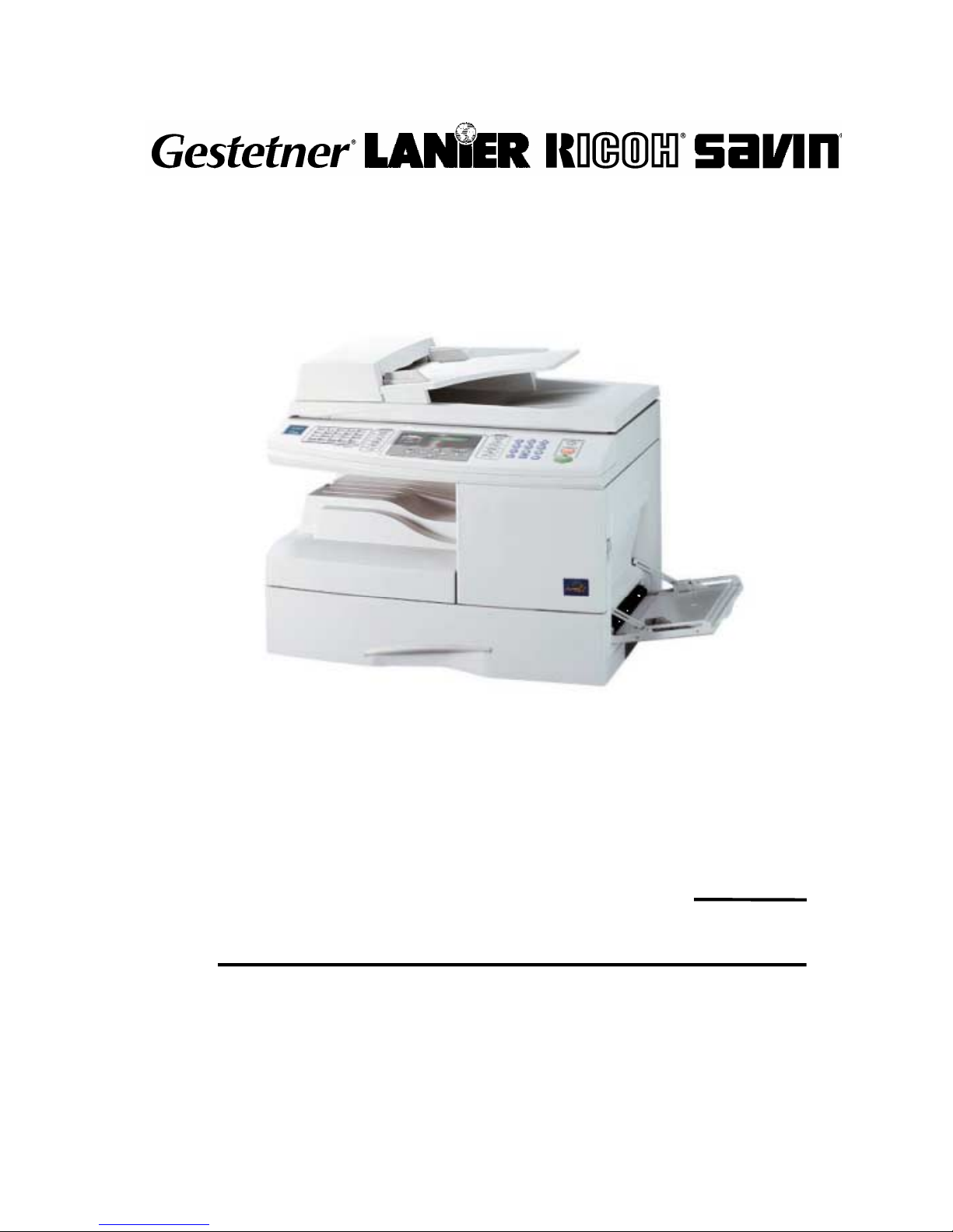
B174
SERVICE DOCUMENTATION
001955MIU
RICOH GROUP COMPANIES
Page 2

Page 3

B174
SERVICE DOCUMENTATION
RICOH GROUP COMPANIES
®
®
Page 4

Page 5

B174
SERVICE
DOCUMENTATION
001955MIU
Page 6

Page 7

It is the reader's responsibility when discussing the information contained
within this document to maintain a level of confidentiality that is in the best
interest of Ricoh Corporation and its member companies.
NO PART OF THIS DOCUMENT MAY BE REPRODUCED IN ANY
FASHION AND DISTRIBUTED WITHOUT THE PRIOR
PERMISSION OF RICOH CORPORATION.
A
ll product names, domain names or product illustrations, including
desktop images, used in this document are trademarks, registered
trademarks or the property of their respective companies.
They are used throughout this book in an informational or editorial fashion
only and for the benefit of such companies. No such use, or the use o
f
any trade name, or web site is intended to convey endorsement or othe
r
affiliation with Ricoh products.
2004 RICOH Corporation. All rights reserved.
Page 8

Page 9

The Service Manual contains information
regarding service techniques, procedures,
p
rocesses and spare parts of office equipmen
t
distributed by Ricoh Corporation. Users of this
manual should be either service trained o
r
certified by successfully completing a Ricoh
Technical Training Program.
Untrained and uncertified users utilizin
g
information contained in this service manual to
repair or modify Ricoh equipment risk persona
l
injury, damage to property or loss of warrant
y
p
rotection.
Ricoh Corporation
WARNING
Page 10

Page 11
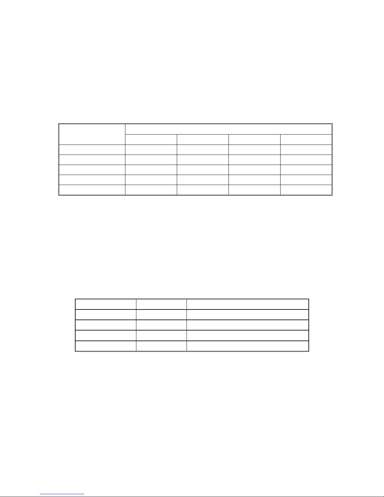
LEGEND
PRODUCT CODE COMPANY
GESTETNER LANIER RICOH SAVIN
B174 DSm515pfd AC106d AC204 AC204
DOCUMENTATION HISTORY
REV. NO. DATE COMMENTS
*
6/2004 Original Printing
Page 12

Page 13

SM i B174
B174
TABLE OF CONTENTS
INSTALLATION
1. INSTALLATION............................................................................ 1-1
PREVENTIVE MAINTENANCE
2. PREVENTIVE MAINTENANCE.................................................... 2-1
REPLACEMENT AND ADJUSTMENT
3. REPLACEMENT AND ADJUSTMENT ........................................ 3-1
3.1 GENERAL PRECAUTIONS ON DISASSEMBLY ......................................3-1
Releasing Plastic Latches.....................................................................3-1
3.2 REAR COVER...........................................................................................3-2
3.3 SCANNER ASS'Y...................................................................................... 3-3
3.4 ADF ASS'Y ................................................................................................3-9
3.5 OPE ASS'Y (ALSO KNOWN AS ‘OP-PORT’) .........................................3-11
3.6 RIGHT COVER ASS'Y ............................................................................3-12
Multi Purpose (MP) Tray (Also known as Bypass Tray)......................3-13
Duplex Ass’y ....................................................................................... 3-14
Transfer Roller Ass’y...........................................................................3-14
3.7 FUSER ASS'Y (ALSO KNOWN AS ‘FUSING UNIT’) ..............................3-15
3.8 EXIT ASS'Y ............................................................................................. 3-17
3.9 COPY TRAY............................................................................................3-18
3.10 DRIVE ASS'Y ........................................................................................3-19
3.11 SMPS & HVPS (ALSO KNOWN AS ‘PSU’ AND ‘POWER PACK) ........3-20
3.12 LSU (LASER SCANNING UNIT) ...........................................................3-21
3.13 LEFT COVER ........................................................................................ 3-22
3.14 MAIN FRAME ASS'Y.............................................................................3-23
3.15 MP ASS'Y (MULTI PURPOSE ASS’Y) ..................................................3-25
3.16 FEED ASS'Y..........................................................................................3-27
3.17 PICK UP ASS'Y.....................................................................................3-28
3.18 MAIN BOARD........................................................................................3-29
3.19 LIU BOARD ...........................................................................................3-30
TROUBLESHOOTING
4. TROUBLESHOOTING ................................................................. 4-1
4.1 ERROR MESSAGES ................................................................................4-1
4.2 ABNORMAL IMAGE PRINTING AND DEFECTIVE ROLLERS.................4-3
4.3 TROUBLESHOOTING ..............................................................................4-4
4.3.1 SCANNER ........................................................................................ 4-4
Page 14

B174 ii SM
COPY....................................................................................................4-4
PC-SCAN..............................................................................................4-5
4.3.2 FAX...................................................................................................4-6
FAX/TELEPHONE PRECAUTIONS .....................................................4-6
4.3.3 PRINT QUALITY...............................................................................4-7
No Image ............................................................................................4-10
All Black .............................................................................................. 4-12
Vertical White Line (Band) ..................................................................4-13
Dark Image .........................................................................................4-14
Background.........................................................................................4-15
Ghost ..................................................................................................4-16
Black Spot...........................................................................................4-17
Horizontal Band ..................................................................................4-18
Irregular Density .................................................................................4-19
White Spot .......................................................................................... 4-20
Trembling at the End When OHP Printing ..........................................4-21
Poor Fusing Grade..............................................................................4-22
4.3.4 MALFUNCTION.............................................................................. 4-23
No Power (LCD NO display LED Off) .................................................4-26
Fuser Error..........................................................................................4-27
Paper Jam (Mis-Feeding) ...................................................................4-28
Paper Jam (Jam 1) .............................................................................4-29
Engine Error........................................................................................4-30
4.3.5 TONER CARTRIDGE AND DRUM CARTRIDGE SERVICE .......... 4-31
Precautions on Safe-keeping of the Drum Cartridge ..........................4-31
Service for the Life of Toner Cartridge ................................................4-31
Symptoms of a defective toner cartridge.............................................4-32
4.3.6 PROBLEMS CAUSED BY SOFTWARE.........................................4-35
The printer is not working (1) ..............................................................4-35
The printer is not working (2) ..............................................................4-36
Abnormal Printing ...............................................................................4-37
Spooling Error.....................................................................................4-38
SERVICE TABLES
5. SERVICE TABLES....................................................................... 5-1
5.1 USER MODE .................................................................................................5-1
5.2 TECH MODE .............................................................................................5-3
5.2.1 HOW TO ENTER SERVICE MODE .................................................5-3
5.2.2 SETTING UP THE SYSTEM IN TECH MODE .................................5-3
5.2.3 SYSTEM DATA ................................................................................5-5
DIALING MODE....................................................................................5-5
MODEM SPEED...................................................................................5-5
ERROR RATE ...................................................................................... 5-5
SET TX LEVEL .....................................................................................5-5
SILENCE TIME.....................................................................................5-5
5.2.4 MEMORY CLEAR.............................................................................5-6
CLEAR ALL MEMORY .........................................................................5-6
Page 15

SM iii B174
5.2.5 MAINTENANCE ...............................................................................5-6
CLEAN DRUM ......................................................................................5-6
NOTIFY TONER LOW ..........................................................................5-6
SWITCH TEST .....................................................................................5-6
MODEM TEST......................................................................................5-7
SRAM TEST .........................................................................................5-7
DRAM TEST .........................................................................................5-7
ROM TEST ...........................................................................................5-7
PATTERN TEST...................................................................................5-7
CLEAR COUNT ....................................................................................5-7
ANSWER ON CNG............................................................................... 5-7
ADJUST SHADING...............................................................................5-8
FLASH UPGRADE................................................................................5-8
PROGRAM DIAL ..................................................................................5-8
REMOTE TEST ....................................................................................5-8
5.2.6 REPORTS/HELP..............................................................................5-9
PROTOCOL DUMP LIST......................................................................5-9
SYSTEM DATA ....................................................................................5-9
5.3 IDENTIFY SALE DATE .............................................................................5-9
5.4 FIRMWARE DOWNLOAD.......................................................................5-10
5.4.1 LOCAL MACHINE UPDATE...........................................................5-10
RCP (Remote Control Panel) mode....................................................5-10
To get the system data list .................................................................. 5-10
5.4.2 RE-PROGRAMMING PROCEDURE AFTER DOWNLOAD ........... 5-11
5.4.3 RECOVERY PROCEDURE............................................................5-11
5.4.4 REMOTE MACHINE UPDATE ....................................................... 5-11
How to update firmware by remote fax ...............................................5-11
5.5 PROCEDURE TO SET COUNTRY CODE.............................................. 5-12
Procedure ........................................................................................... 5-12
5.6 ENGINE TEST MODE.............................................................................5-13
5.6.1 TO ENTER THE ENGINE TEST MODE.........................................5-13
5.6.2 DIAGNOSTIC ................................................................................. 5-13
5.6.3 STATUS PRINT.............................................................................. 5-14
DETAILED DESCRIPTIONS
6. DETAILED DESCRIPTION .......................................................... 6-1
6.1 MAIN PBA (ALSO KNOWN AS MAIN BOARD) ........................................6-1
6.1.1 SUMMARY ....................................................................................... 6-1
6.2 CIRCUIT OPERATION..............................................................................6-2
6.2.1 FAX TRANSCEIVER ........................................................................6-2
General .................................................................................................6-2
Modem (u44) ........................................................................................6-2
6.3 SCANNER .................................................................................................6-2
6.3.1 SUMMARY .......................................................................................6-2
CCD ......................................................................................................6-2
Page 16

B174 iv SM
6.3.2 KEY FEATURES ..............................................................................6-3
Overview...............................................................................................6-3
Pixel processing structure.....................................................................6-3
Shading Correction ...............................................................................6-3
Gamma Correction................................................................................6-3
Binary conversion (mono) ..................................................................... 6-4
Scaling of input image...........................................................................6-4
Intelligent scan motor controller ............................................................6-4
Auto-Run...............................................................................................6-4
Processed data output format in DTM (Data Transfer Module) ............6-4
Others ...................................................................................................6-4
6.4 SMPS & HVPS (ALSO KNOWN AS PSU AND POWER PACK)...............6-5
6.4.1 SUMMARY OF SMPS ......................................................................6-5
6.4.2 SUMMARY OF HVPS.......................................................................6-5
6.5 ENGINE CONTROLLER ...........................................................................6-5
6.5.1 FUSING CONTROL/THERMISTOR CIRCUIT .................................6-5
6.5.2 PAPER DETECTION CIRCUIT ........................................................ 6-6
1) Cover Open Detection ......................................................................6-6
2) Paper Empty Detection.....................................................................6-6
3) Paper Feeding ..................................................................................6-6
4) Paper Exit Detection .........................................................................6-6
6.6 LIU (ALSO KNOWN AS NCU)...................................................................6-7
6.6.1 SUMMARY ....................................................................................... 6-7
6.6.2 DIALER.............................................................................................6-7
TONE DIAL...........................................................................................6-7
PULSE DIAL .........................................................................................6-7
SPECIFICATIONS
SPECIFICATIONS
1. GENERAL SPECIFICATIONS.....................................................................7-1
2. PRINT SPECIFICATION ............................................................................. 7-2
3. SCAN SPECIFICATION .............................................................................. 7-2
4. COPY SPECIFICATION..............................................................................7-3
5. TELEPHONE SPECIFICATION ..................................................................7-3
6. FAX SPECIFICATION ................................................................................. 7-3
7. PAPER HANDLING.....................................................................................7-4
8. CONSUMABLES .........................................................................................7-4
APPENDIX
APPENDIX
BLOCK DIAGRAMS.........................................................................................8-1
CONNECTION DIAGRAMS.............................................................................8-2
PARTS CATALOG
SEE PARTS CATALOG SECTION FOR DETAILED TABLE OF CONTENTS
Page 17
PRECAUTIONS
Please carefully read the cautions below to prevent accidents while servicing the
machine.
WARNING FOR SAFETY
1. Request the service by qualified service person.
The service for this machine must be performed by a qualified service person.
It is dangerous if an unqualified service person or user tries to repair the
machine.
2. Do not rebuild it discretionary.
Do not disassemble, fix, and rebuilt the machine. If you do, the machine may
not work and an electric shock or a fire can occur.
3. Laser Safety Statement
The Printer is certified in the U.S. to conform to the requirements of DHHS 21
CFR, chapter 1 Subchapter J for Class 1(1) laser products, and elsewhere, it is
certified as a Class I laser product conforming to the requirements of IEC 825.
Class I laser products are not considered to be hazardous. The laser system
and printer are designed so there is never any human access to laser radiation
above a Class I level during normal operation, user maintenance, or prescribed
service condition.
WARNING
Never operate or service the printer with the protective cover removed from
Laser/Scanner assembly. The reflected beam, although invisible, can
damage your eyes. When using this product, these basic safety
precautions should always be followed to reduce risk of fire, electric shock,
and injury to persons.
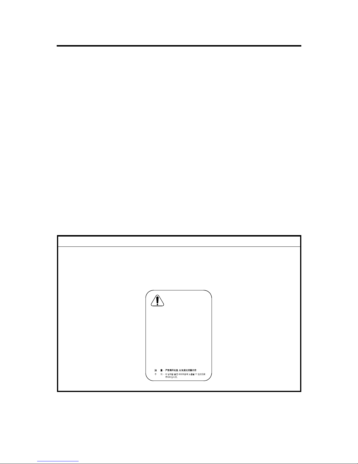
CAUTION - INVISIBLE LASER RADIATION
WHEN THIS COVER OPEN.
DO NOT OPEN THIS COVER.
VORSICHT - UNSICHTBARE LASERSTRAHLUNG,
WENN ABDECKUNG GE…FFNET.
NICHT DEM STRAHL AUSSETZENz
ATTENTION - RAYONNEMENT LASER INVISIBLE EN CAS
DÕOUVERTURE. EXPOSITION DANGEREUSE
AU FAISCEAU.
ATTENZIONE - RADIAZIONE LASER INVISIBILE IN CASO DI
APERTURA. EVITARE LÕESPOSIZIONE AL
FASCIO.
PRECAUCION - RADIACION LASER IVISIBLE CUANDO SE ABRE.
EVITAR EXPONERSE AL RAYO.
ADVARSEL. - USYNLIG LASERSTR LNING VED BNING, N R
SIKKERHEDSBRYDERE ER UDE AF FUNKTION.
UNDG UDSAETTELSE FOR STR LNING.
ADVARSEL. - USYNLIG LASERSTR LNING N R DEKSEL
PNES. STIRR IKKE INN I STR LEN.
UNNG EKSPONERING FOR STR LEN.
VARNING - OSYNLIG LASERSTR LNING N R DENNA DEL
R PPNAD OCH SP RREN R URKOPPLAD.
BETRAKTA EJ STR LEN. STR LEN R FARLIG.
VARO! - AVATTAESSA JA SUOJALUKITUS OHITETTAESSA
OLET ALTTIINA N KYM TT M LLE LASERS TEILYLLE L KATSO S TEESEEN.
CAUTION.WMF
Page 18

CAUTION FOR SAFETY
PRECAUTION RELATED NOXIOUS MATERIAL
It is possible to be harmed from noxious material if you ignore the below
information.
1. Do not touch the damaged LCD. Noxious liquid to a human body exists in the
LCD. If it is got into the mouth, immediately see a doctor. If it gets into the eyes
or on the skin, immediately wash off with flowing water for 15 minutes and then
see a doctor.
2. The toner in a printer cartridge contains a chemical material, if swallowed,
might harm a human body.
Please keep the toner cartridge away from children.
PRECAUTION RELATED ELECTRIC SHOCK OR FIRE
It is possible to get an electric shock or burn by fire if you don't follow the
instructions of the manual.
1. Use the exact voltage and wall socket. If not, a fire or an electric leakage can
occur.
2. Use an authorized power cord. Use the power code supplied with machine. A
fire can occur when an over current condition flows in the power cord.
3. Do not insert many cords into an outlet. A fire can occur due to an over current
condition in the outlet.
4. Do not put water or other liquid, pin, clip, etc in the machine. It can cause a fire,
electric shock, or malfunction. If this occurs, immediately turn off the power off
and remove the power plug from outlet.
5. Do not touch the power plug with a wet hand. When servicing, remove the
power plug from the outlet.
6. Use caution when inserting or unplugging the power plug. The power plug has
to be inserted completely. If not, a fire can occur due to a poor contact. When
unplugging the power cord, grip the plug, not the wire.
7. Do not bend, twist, bind or place other materials on the power cord. Do not use
staples around machine. If the power cord becomes damaged, a fire or electric
shock can occur. A damaged power code must be replaced immediately. Do
not attempt to repair the damaged cord or reuse it. Repairing the cord with
plastic tape can cause a fire or electric shock. Do not spread chemicals or
insecticide on the power cord
8. Check whether the power outlet and the power plug are damaged, compressed
or cracked. When such inferiorities are found, replace it immediately. Do not roll
over the cord when moving the machine.
Page 19

9. Use caution during lightning storms. It may cause a fire or electric shock.
Unplug the power plug off under these conditions. Do not touch cable and
device during a lightning storm.
10. Avoid damp or dusty areas. Do not install the machine in dusty areas or around
humidifiers. A fire can occur. Clean the plug with dried fabric cloth to remove
dust.
11. Avoid direct sunlight. Do not install the machine near to a window where it is in
direct sunlight. If the machine operates in direct sunlight for a long periods, the
machine may not work correctly, because the increased inner temperature of
machine.
12. Turn off the machine and unplug the power cord when smoke, a strange smell,
or sound is detected from the machine. A fire can occur if the machine is used
under these conditions.
13. Do not insert steel or metal pieces inside/outside of the machine. Do not insert
metal pieces into the ventilator slots. An electric shock can occur.
PRECAUTION RELATED TO HANDLING THE MACHINE
If you ignore this information, you could get harm and machine could be damaged.
1. Do not install the machine on an uneven surface or slanted floor. Confirm that
the machine is correctly balanced after installation. The machine may fall over if
not balanced correctly.
2. Be careful not to insert a finger or hair in the rotating unit (motor, fan, paper
feeding part, etc) while the machine is operation.
3. Do not place any containers of water or chemical or small metals on top of the
machine. If these objects spill into the machine, a fire or electric shock can
occur.
4. Do not install the machine in areas where moisture or dust exists. For example,
do not install machine near open windows.
5. Do not place candles, burning cigarettes, etc. on the machine. Do not install it
near to a heater.
Page 20

PRECAUTIONS FOR WHEN ASSEMBLY/DISASSEMBLY
Replace parts very carefully. Remember the location of each cable before
removing parts, in order to reconnect it afterwards. Please perform the steps below
before replacing or disassembling any parts.
1. Check the contents stored in the memory. Either print a copy of stored data or
write down all of the needed information. All the stored information will be
erased when the main board is replaced.
2. Disconnect the power cord before servicing or replacing electrical parts.
3. Remove the printer cable.
4. Use formal parts and same standardized goods when replacing parts. Check
the product name, part code, rated voltage, rated current, operating
temperature, etc.
5. Do not use excessive force when loosening or tightening plastic components.
6. Be careful not to drop small parts or objects in the machine.
ESD PRECAUTIONS
Certain semiconductor devices can be easily damaged by static electricity. Such
components are commonly called “Electro statically Sensitive (ES) Devices”, or
ESD’s. Examples of typical ESD’s are: integrated circuits, some field effect
transistors, and semiconductor “chip” components.
The techniques outlined below should be followed to help reduce the incidence of
component damage caused by static electricity.
CAUTION
Be sure no power is applied to the chassis or circuit, and observe all other
safety precautions.
1. Immediately before handling a semiconductor component or semiconductorequipped assembly, drain off any electrostatic charge on your body by touching
a known earth ground. Alternatively, use a commercially available wrist strap
device, which should be removed for your personal safety reasons prior to
applying power to the unit under test.
2. After removing an electrical assembly equipped with ESD’s, place the
assembly on a conductive surface, such as aluminum or copper foil, or
conductive foam, to prevent electrostatic charge buildup in the vicinity of the
assembly.
3. Use only a grounded tip soldering iron to solder an ESD’s.
Page 21

4. Only use an “anti-static” solder removal device. Some solder removal devices
not classified as “anti-static” and can generate an electrical charge sufficient to
damage ESD’s.
5. Do not use Freon-propelled chemicals. When sprayed, these can generate
electrical charges sufficient to damage ESD’s.
6. Do not remove a replacement ESD from its protective packaging until
immediately before installing it. Most replacement ESD’s are packaged with all
leads shorted together by conductive foam, aluminum foil, or a comparable
conductive material.
7. Immediately before removing the protective shorting material from the leads of
a replacement ESD, touch the protective material to the chassis or circuit
assembly into which the device will be installed.
8. Maintain continuous electrical contact between the ESD and the assembly into
which it will be installed, until completely plugged or soldered into the circuit.
9. Minimize bodily motions when handling unpackaged replacement ESD’s.
Normal motions, actions such as brushing together of clothing fabric or lifting
one’s foot from a carpeted floor, can generate static electricity sufficient to
damage an ESD.
Page 22

Page 23
INSTALLATION
PREVENTIVE MAINTENANCE
REPLACEMENT AND ADJUSTMENT
TROUBLESHOOTING
SERVICE TABLES
DETAILED DESCRIPTIONS
SPECIFICATIONS
APPENDIX
TAB
POSITION 2
TAB
POSITION 1
TAB
POSITION 3
TAB
POSITION 4
TAB
POSITION 6
TAB
POSITION 5
TAB
POSITION 8
TAB
POSITION 7
Page 24

Page 25

INSTALLATION
Page 26

Page 27

INSTALLATION
SM 1-1 B174
Installation
1. INSTALLATION
Refer to the operating instructions.
Page 28

Page 29

PREVENTIVE MAINTENANCE
Page 30

Page 31
PREVENTIVE MAINTENANCE
SM 2-1 B174
Preventive
Maintenance
2. PREVENTIVE MAINTENANCE
The replacement cycle interval shown below is for maintenance.
Environmental conditions and differences in how the machine is used will change
this interval.
The cycle period shown is for reference only.
Component Replacement Cycle Done by
ADF Rubber Pad Ass’y 20,000 Pages Service
Scanner
ADF Pick-up Ass’y 50,000 Pages Service
Rubber - Paper Pick-up - Right
Rubber - Paper Pick-up - Left
75,000 Pages Service
Transfer Roller 75,000 Pages Service
Printer
Fuser 75,000 Pages Service
Page 32

Page 33

REPLACEMENT AND ADJUSTMENT
Page 34

Page 35

GENERAL PRECAUTIONS ON DISASSEMBLY
SM 3-1 B174
Replacement
Adjustment
3. REPLACEMENT AND ADJUSTMENT
3.1 GENERAL PRECAUTIONS ON DISASSEMBLY
When you disassemble and assemble components, you must use extreme caution.
Cables are near parts that move. Because of this, install the cables carefully. If
components are removed, cables moved during the procedure must be put as near
as possible to their initial positions. Before you remove a component from the
machine, make a note of the cable routing.
Before you do work on the machine, you must do these steps:
1. Make sure that no documents are stored in memory.
2. Disconnect the power cord.
3. Remove the toner and drum cartridges before you disassemble parts.
4. Use a flat and clean surface.
5. Replace only with approved components.
6. Be careful when you remove plastic components. Do not use force.
7. Make sure that all components are in their correct positions.
Releasing Plastic Latches
Many parts set in their positions with plastic latches. The latches break easily.
Release them carefully. Push the hook end of the latch away from the part to which
it is latched to remove these parts.
B174R979.WMF
Page 36

REAR COVER
B174 3-2 SM
3.2 REAR COVER
1. Remove the six screws that hold
the Rear Cover.
2. Remove the Rear Cover [A] as
shown.
B174R900.WMF
[A]
Page 37

SCANNER ASS'Y
SM 3-3 B174
Replacement
Adjustment
3.3 SCANNER ASS'Y
1. Before you remove the Scanner Ass'y
[A], you must remove:
- Rear Cover (!3.2)
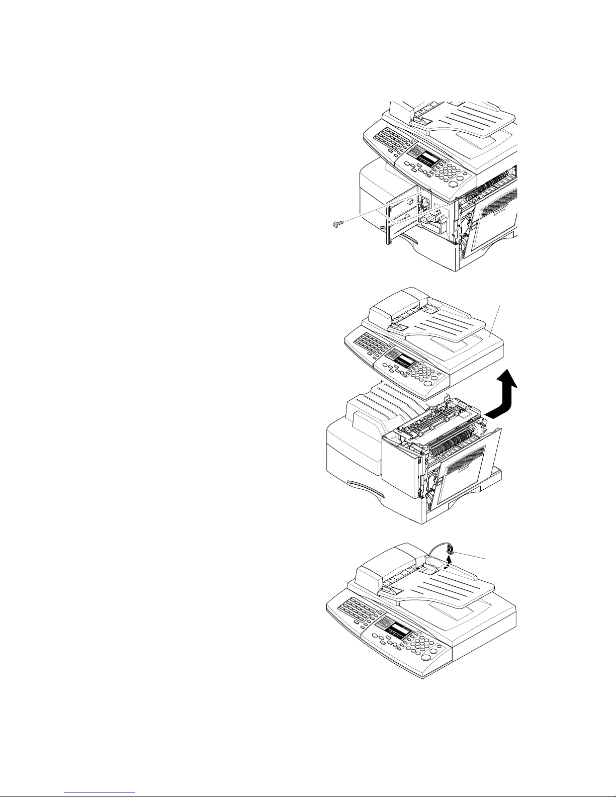
2. Disconnect the connector and the
CCD cable [B].
NOTE: To prevent damage to the
CCD cable connector, pull the
cable out carefully. Pull in a
line with the connector, not at
an angle.
3. Remove the three screws, as shown.
4. Open the Right Cover assembly [C]
first to open the Front Cover [D].
• Close the front cover first when you
assemble the machine.
B174R902.WMF
B174R903.WMF
1
2
B174R904.WMF
[A]
[B]
[C]
[D]
Page 38
SCANNER ASS'Y
B174 3-4 SM
5. Remove two screws.
6. Pull up the Scanner Ass'y [A] in the
direction of the arrow.
7. Disconnect the connector [B] from the
Platen Ass'y.
B174R905.WMF
B174R906.WMF
B174R907.WMF
[A]
[B]
Page 39

SCANNER ASS'Y
SM 3-5 B174
Replacement
Adjustment
8. Open the Platen Ass’y [A] as shown by
the arrow.
Pull up the Platen Ass'y and remove it.
9. Remove the three screws securing the
Platen Ass’y.
10. Pull up the OPE Ass'y [B] and remove
it ( x 1).
B174R909.WMF
B174R908.WMF
B174R978.WMF
[A]
[B]
Page 40
SCANNER ASS'Y
B174 3-6 SM
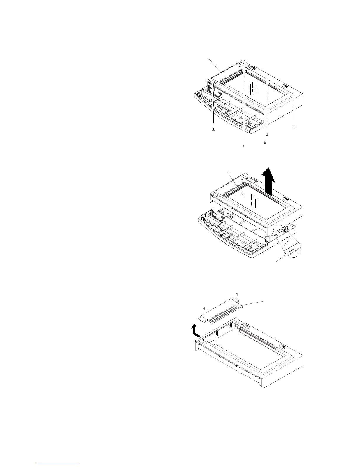
11. Remove the five screws that hold the
Scan Upper Ass'y [A].
12. Remove the Scan Upper Ass'y that
holds the platen glass [B]. (Release one
hook [C].)
NOTE: When you disassemble the
Scan Ass’y, make sure that
your work area is clean. Dirt or
dust on the scan head can
cause unsatisfactory scanned
image quality.
13. Remove the Dummy Upper Ass’y [D]
( x 2).
B174R910.WMF
B174R911.WMF
B174R912.WMF
[D]
[A]
[C]
[B]
Page 41

SCANNER ASS'Y
SM 3-7 B174
Replacement
Adjustment
14. Remove the Channel Base Frame [A]
( x 4).
15. Remove the Dummy Scan-Lower [B]
( x 5).
16. Remove the CCD cable [C].
B174R913.WMF
B174R914.WMF
B174R915.WMF
[A]
[B]
[C]
Page 42
SCANNER ASS'Y
B174 3-8 SM
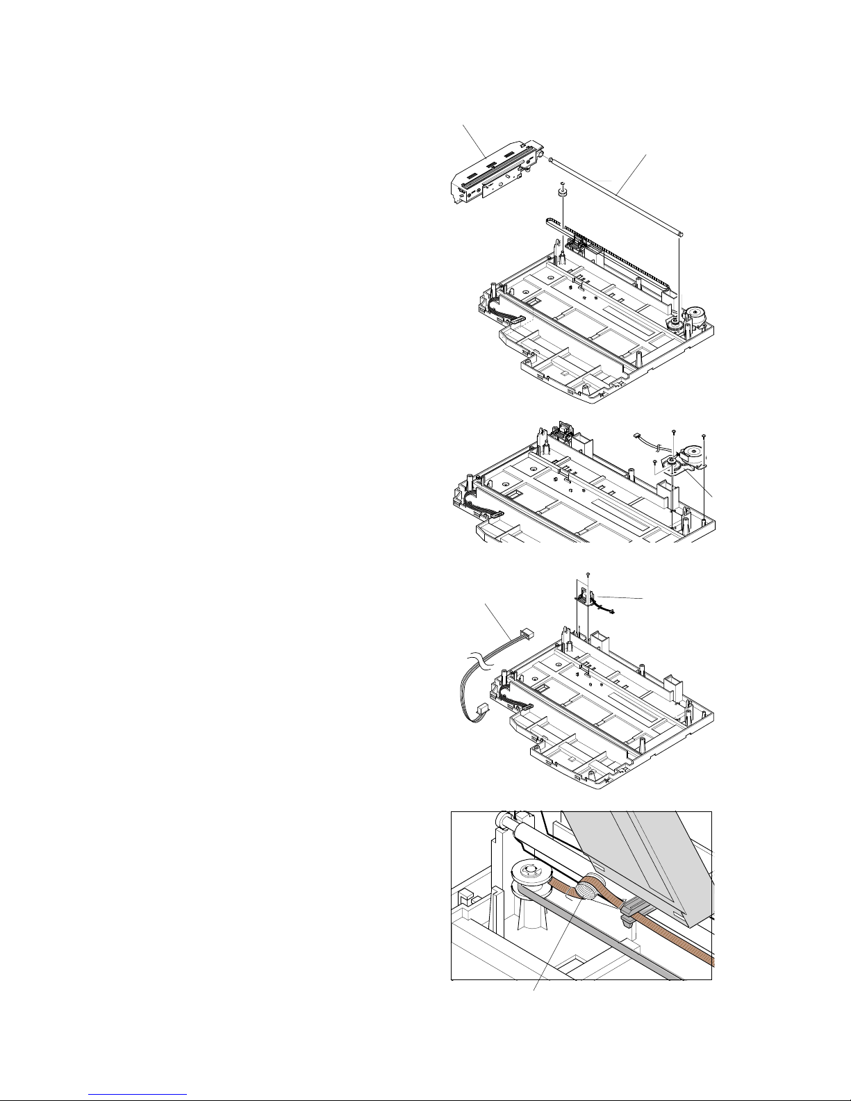
17. Pull up the Shaft CCD [A], and remove
the Scanner Unit [B].
18. Remove the Motor Bracket [C] ( x 3).
19. Disconnect the OPE Harness [D] from
the Platen board [E]. Remove the
Platen board ( x 2).
NOTE: Be very careful when you attach the
CCD Unit back to the Platen
Ass'y. The CCD Unit is on the
right side of the Belt Tension
Spring [F].
B174R916.WMF
B174R917.WMF
B174R918.WMF
B174R919.WMF
[A]
[B]
[D]
[E]
[F]
[C]
Page 43
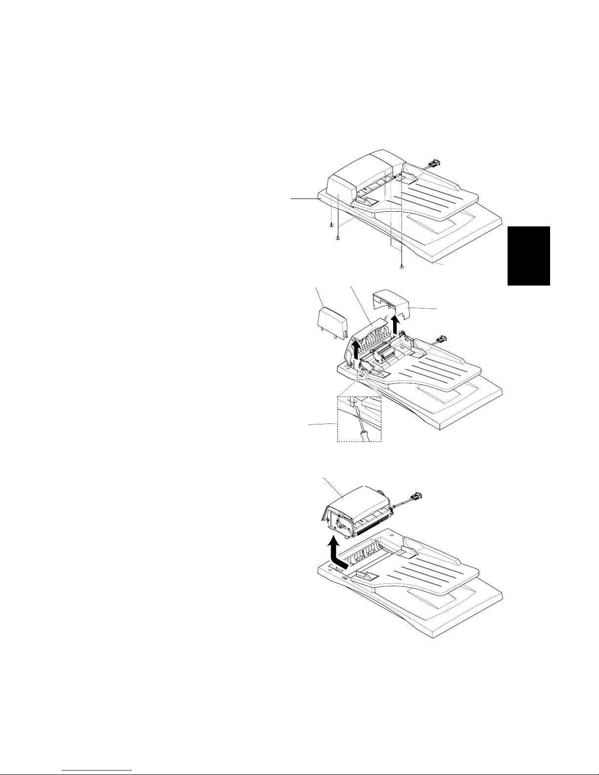
ADF ASS'Y
SM 3-9 B174
Replacement
Adjustment
3.4 ADF ASS'Y
1. Before you remove the ADF Ass'y [A], you must remove:
- Rear Cover (! 3.2)
- Scanner Ass'y (! 3.3)
2. Remove the five screws from the
Platen Ass’y.
3. Open the ADF Upper Cover [B].
Remove Side Cover R [C]. Release
Side Cover L [D]. To do this, use a
sharp tool or small screwdriver as
shown [E]. Then remove Side Cover L.
4. Pull up the ADF Ass'y [F] and remove
it.
B174R920.WMF
B174R921.WMF
B174R922.WMF
[A]
[B]
[C]
[D]
[F]
[E]
Page 44
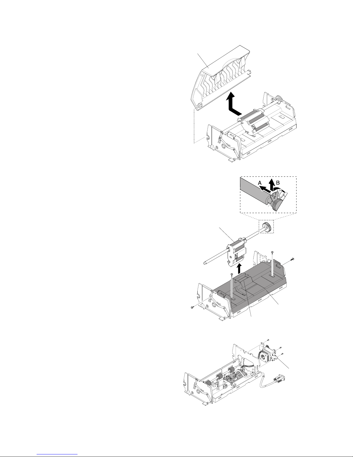
ADF ASS'Y
B174 3-10 SM
5. Remove the ADF Upper Cover [A].
6. Remove the ADF Pick-up Ass’y [B] (!
2). Remove the ADF Upper [C] ( x 4).
[D]: ADF Rubber Pad Ass’y (! 2)
7. Remove the ADF Motor ass'y [E]
( x 3).
B174R923.WMF
B174R924.WMF
B174R925.WMF
[B]
[C]
[A]
[D]
[E]
Page 45

OPE ASS'Y (ALSO KNOWN AS ‘OP-PORT’)
SM 3-11 B174
Replacement
Adjustment
3.5 OPE ASS'Y (ALSO KNOWN AS ‘OP-PORT’)
1. Before you remove the OPE Ass'y, you must remove:
- Rear Cover (! 3.2)
- Scanner Ass'y (! 3.3)
2. Remove the OPE board [A] and the
LCD Module [B] from the OPE Cover
[C] ( x 10).
3. Remove the contact rubbers [D] from
the unit.
4. Remove the key pad [E] from the unit.
B174R926.WMF
B174R927.WMF
B174R928.WMF
[A]
[B]
[C]
[D]
[E]
Page 46
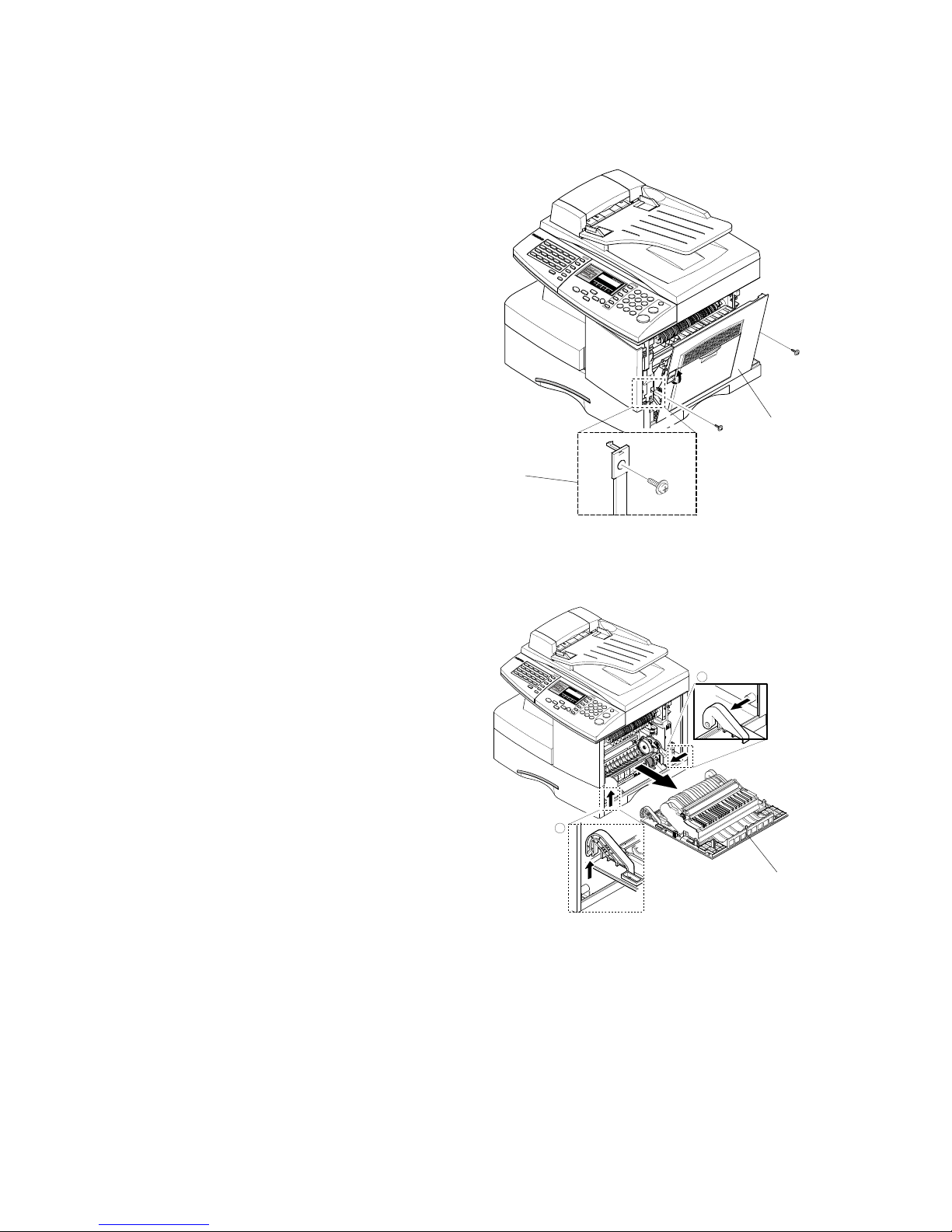
RIGHT COVER ASS'Y
B174 3-12 SM
3.6 RIGHT COVER ASS'Y
1. Remove two screws to release the
Stopper [A] (Main Frame side) that
holds the Right Cover [B] to the Main
Frame.
2. Fully open the Right Cover door [C].
Lift the left hand hinge " to release
it. Then push the door assembly to
the left to release the right hand
hinge #.
B174R929.WMF
1
2
B174R930.WMF
[A]
[B]
[C]
Page 47
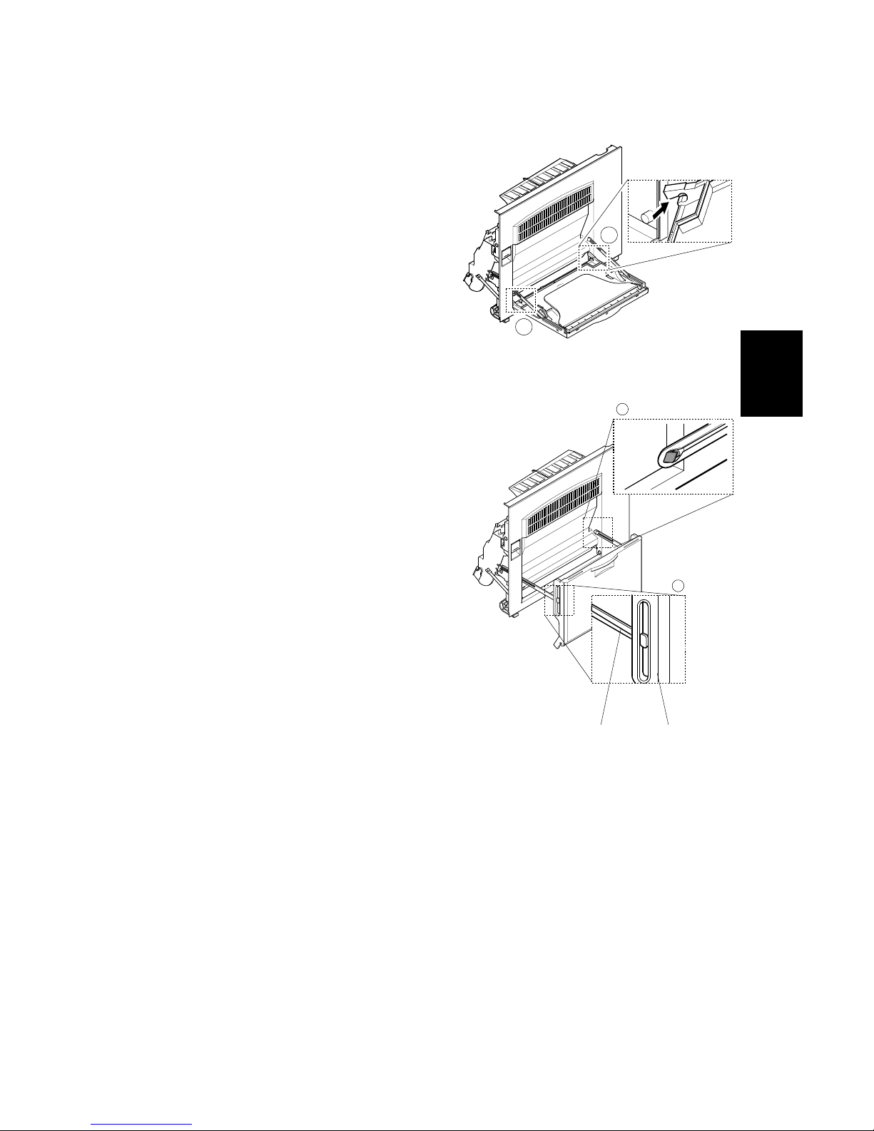
RIGHT COVER ASS'Y
SM 3-13 B174
Replacement
Adjustment
Multi Purpose (MP) Tray (Also known as Bypass Tray)
1. To disassemble the MP tray, release
the lower hinges ".
2. As shown at ", align the door supports
in a horizontal position. This will let you
remove the Tray-Case [A] from the Tray
Links. To remove the Tray-Links [B],
adjust the position of the Tray Links to a
45-degree angle to align the slot in the
link correctly, as shown at #.
1
1
B174R931.WMF
1
2
B174R932.WMF
[A] [B]
Page 48

RIGHT COVER ASS'Y
B174 3-14 SM
Duplex Ass'y
1. Remove the Duplex Ass'y [A] from the
Side Door Ass'y [B] (release the plastic
clips, 2 on each side).
Transfer Roller Ass'y
1. Remove the Transfer Roller Ass’y [B]
(!2).
B174R933.WMF
B174R934.WMF
[A]
[B]
[B]
Page 49
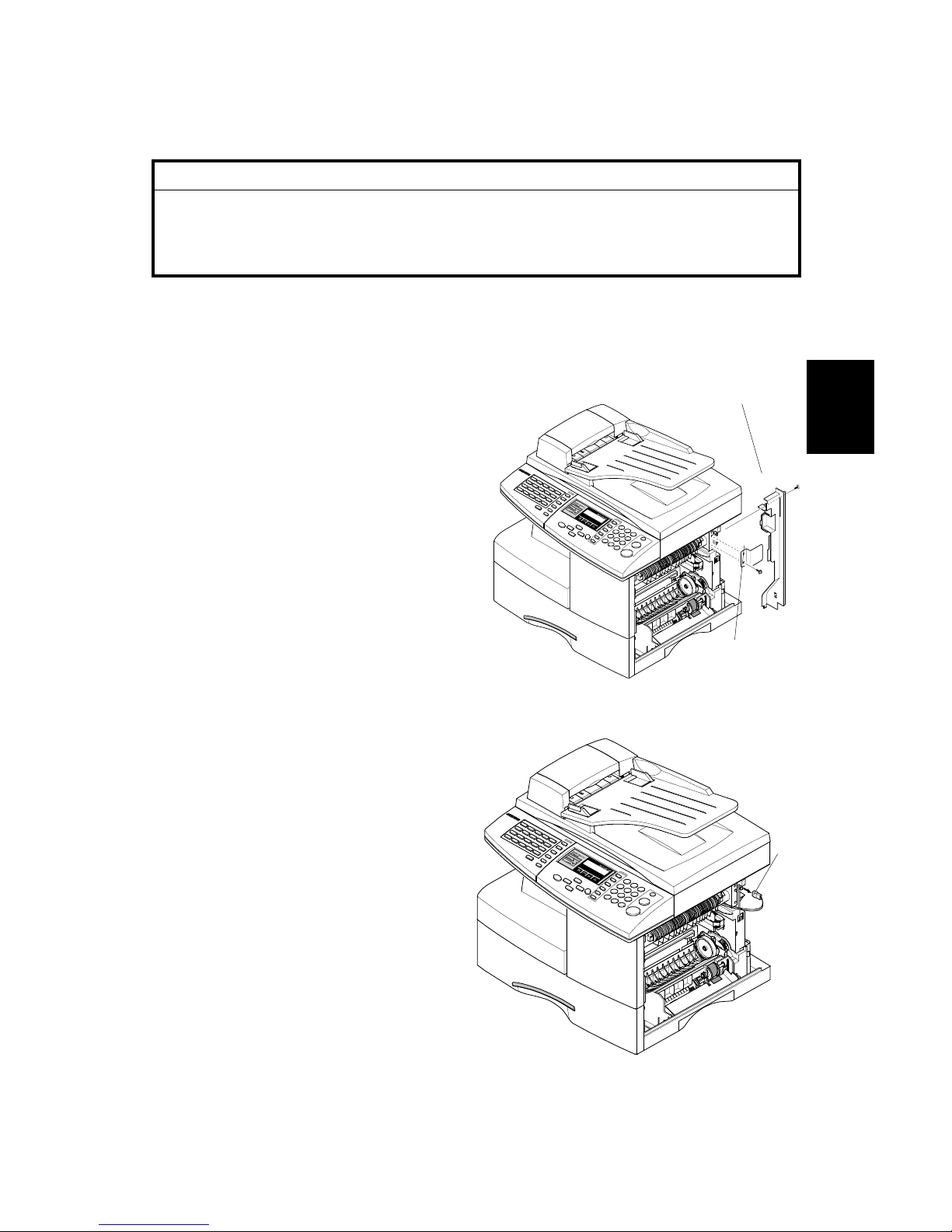
FUSER ASS'Y (ALSO KNOWN AS ‘FUSING UNIT’)
SM 3-15 B174
Replacement
Adjustment
3.7 FUSER ASS'Y (ALSO KNOWN AS ‘FUSING UNIT’)
CAUTION
The fusing unit has tapping screws. Assembly/disassembly should be kept
to a minimum. Adjustments again and again can cause failure. To avoid
hazardous situations, do not replace any components inside the fusing unit
such as thermistor, thermostat, hot roller, stripper pawls, fusing lamp, etc.
1. Before you remove the Fuser Ass'y, you must make sure that power is off.
Then remove:
- Rear Cover Ass'y (! 3.2)
- Right Cover Ass'y (! 3.6)
2. Remove the Connector Cover [A]
and the Cover Bracket [B] ( x 1
each).
3. Disconnect one connector [C].
B174R935.WMF
B174R936.WMF
[B]
[A]
[C]
Page 50
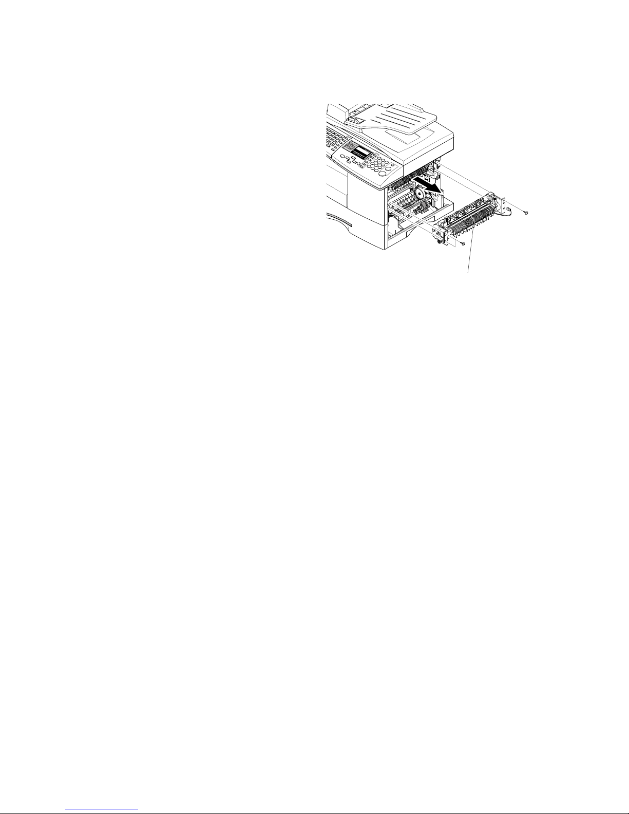
FUSER ASS'Y (ALSO KNOWN AS ‘FUSING UNIT’)
B174 3-16 SM
4. Remove the Fuser Ass'y [A] ( x 3).
(! 2)
B174R937.WMF
[A]
Page 51
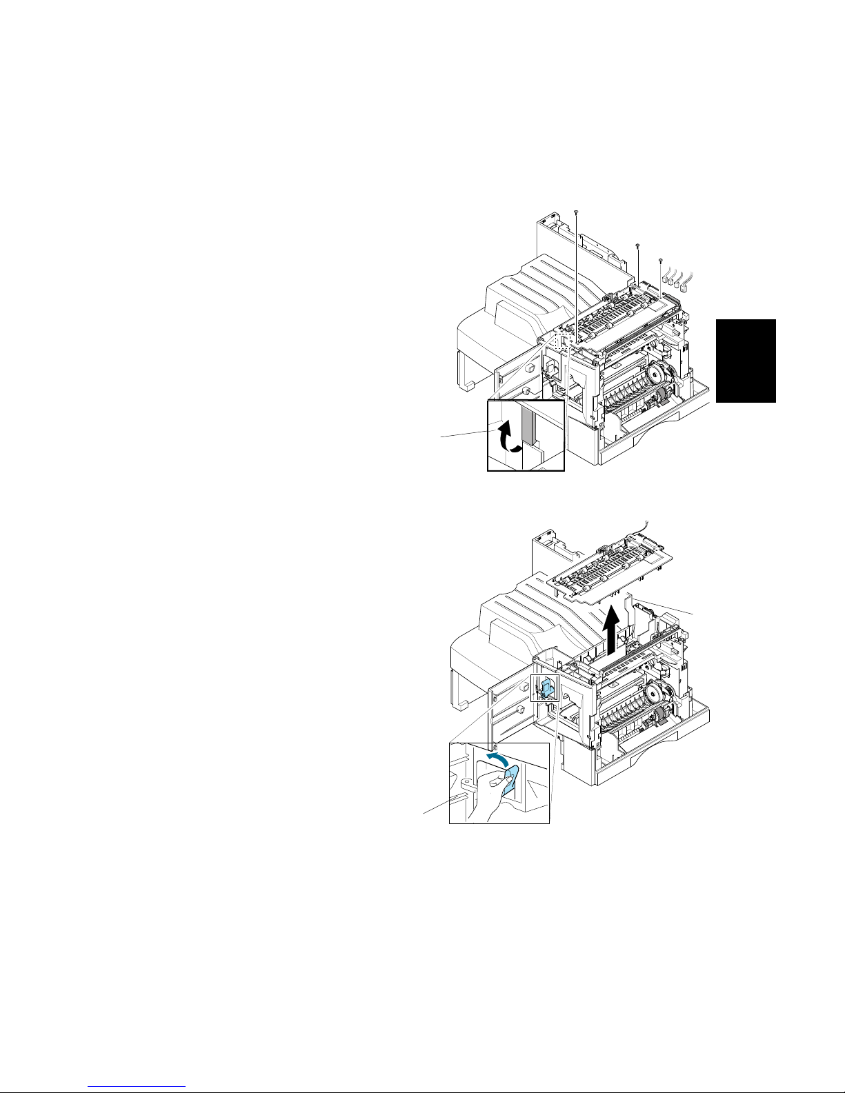
EXIT ASS'Y
SM 3-17 B174
Replacement
Adjustment
3.8 EXIT ASS'Y
1. Before you remove the Exit Ass'y, you must remove:
- Rear Cover (! 3.2)
- Scanner Ass'y (! 3.3)
2. Remove four screws. Then, remove the
harness from the Exit Upper.
Disconnect four connectors and unlatch
the Dummy Base Frame [A], as shown.
3. Move the Exit Roller Release Lever [B]
to the vertical position as shown in the
diagram. Then, lift the Exit Ass'y [C] to
remove it.
B174R941.WMF
B174R942.WMF
[A]
[C]
[B]
Page 52
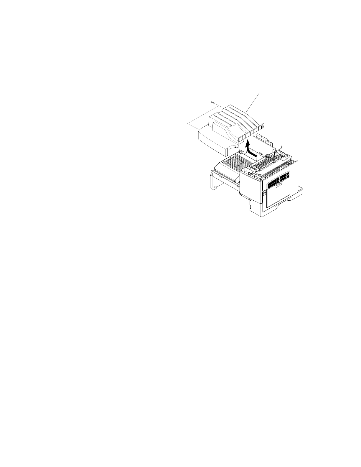
COPY TRAY
B174 3-18 SM
3.9 COPY TRAY
1. Before you remove the Copy Tray, you must remove:
- Rear Cover (! 3.2)
- Scanner Ass'y (! 3.3)
2. Remove the Copy Tray [A] ( x 2).
B174R943.WMF
[A]
Page 53
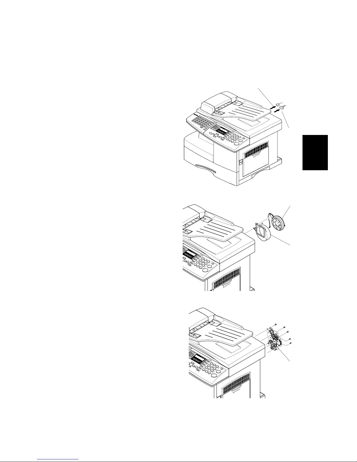
DRIVE ASS'Y
SM 3-19 B174
Replacement
Adjustment
3.10 DRIVE ASS'Y
1. Before you remove the Drive Ass'y, you must remove:
- Rear Cover (! 3.2)
2. Unplug two connectors.
(for Main Motor [A]: 9-pin, for Duplex
Solenoid [B]: 2-pin)
3. Remove the Fan [C] and Duct - Fan
[D] ( x 1).
4. Remove the Drive Ass'y [E] ( x 5).
B174R944.WMF
B174R945.WMF
B174R946.WMF
[C]
[D]
[A]
[B]
[E]
Page 54
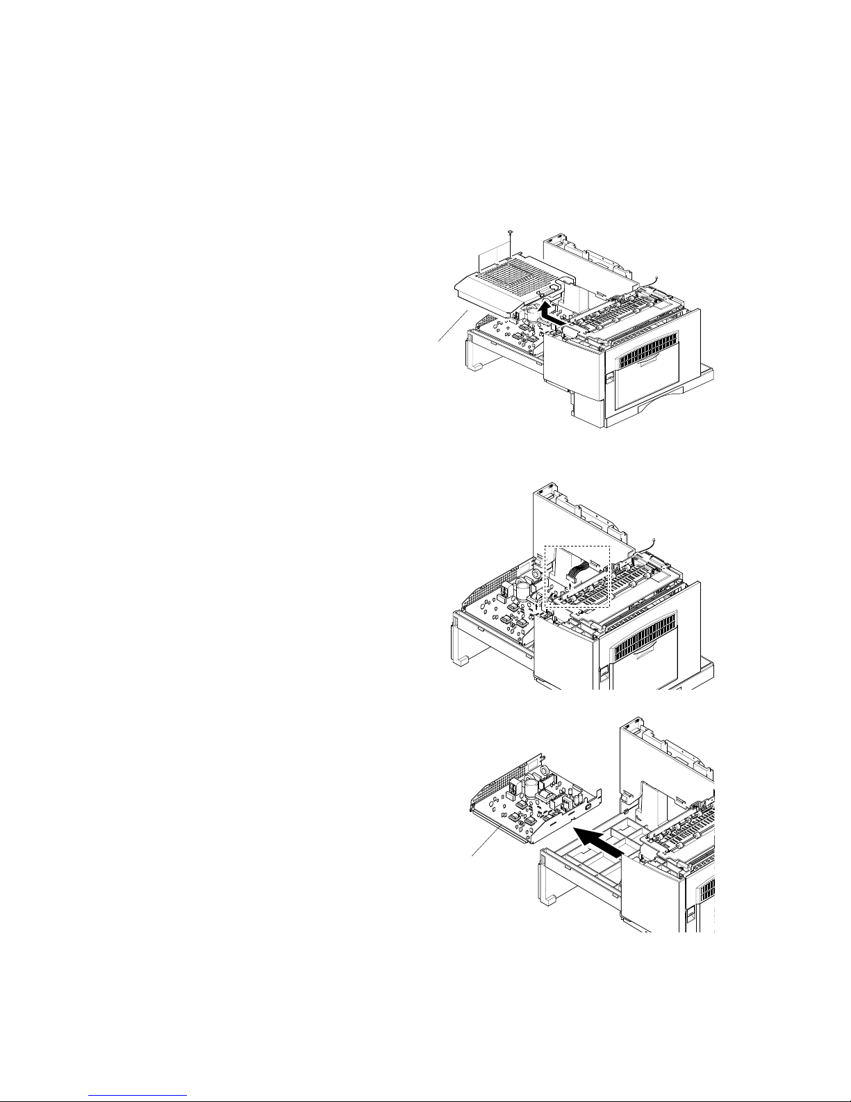
SMPS & HVPS (ALSO KNOWN AS ‘PSU’ AND ‘POWER PACK)
B174 3-20 SM
3.11 SMPS & HVPS (ALSO KNOWN AS ‘PSU’ AND ‘POWER PACK)
1. Before you remove the SMPS & HVPS, you must remove:
- Rear Cover (! 3.2)
- Scanner Ass'y (! 3.3)
- Copy Tray (! 3.9)
2. Remove the Shield SMPS Upper [A]
( x 3).
3. Disconnect all the connectors.
4. Remove the SMPS & HVPS [B].
B174R947.WMF
B174R948.WMF
B174R949.WMF
[B]
[A]
Page 55
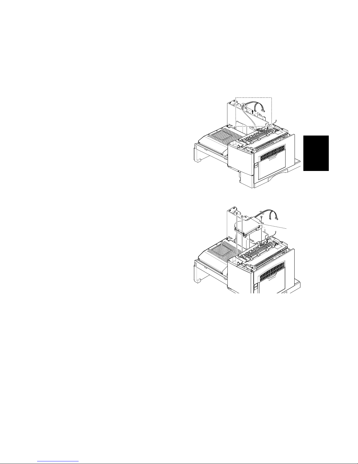
LSU (LASER SCANNING UNIT)
SM 3-21 B174
Replacement
Adjustment
3.12 LSU (LASER SCANNING UNIT)
1. Before you remove the LSU, you must remove:
- Rear Cover (! 3.2)
- Scanner Ass'y (! 3.3)
- Copy Tray (! 3.9)
2. Disconnect two connectors.
3. Remove the LSU [A] ( x 3).
B174R950.WMF
B174R951.WMF
[A]
Page 56
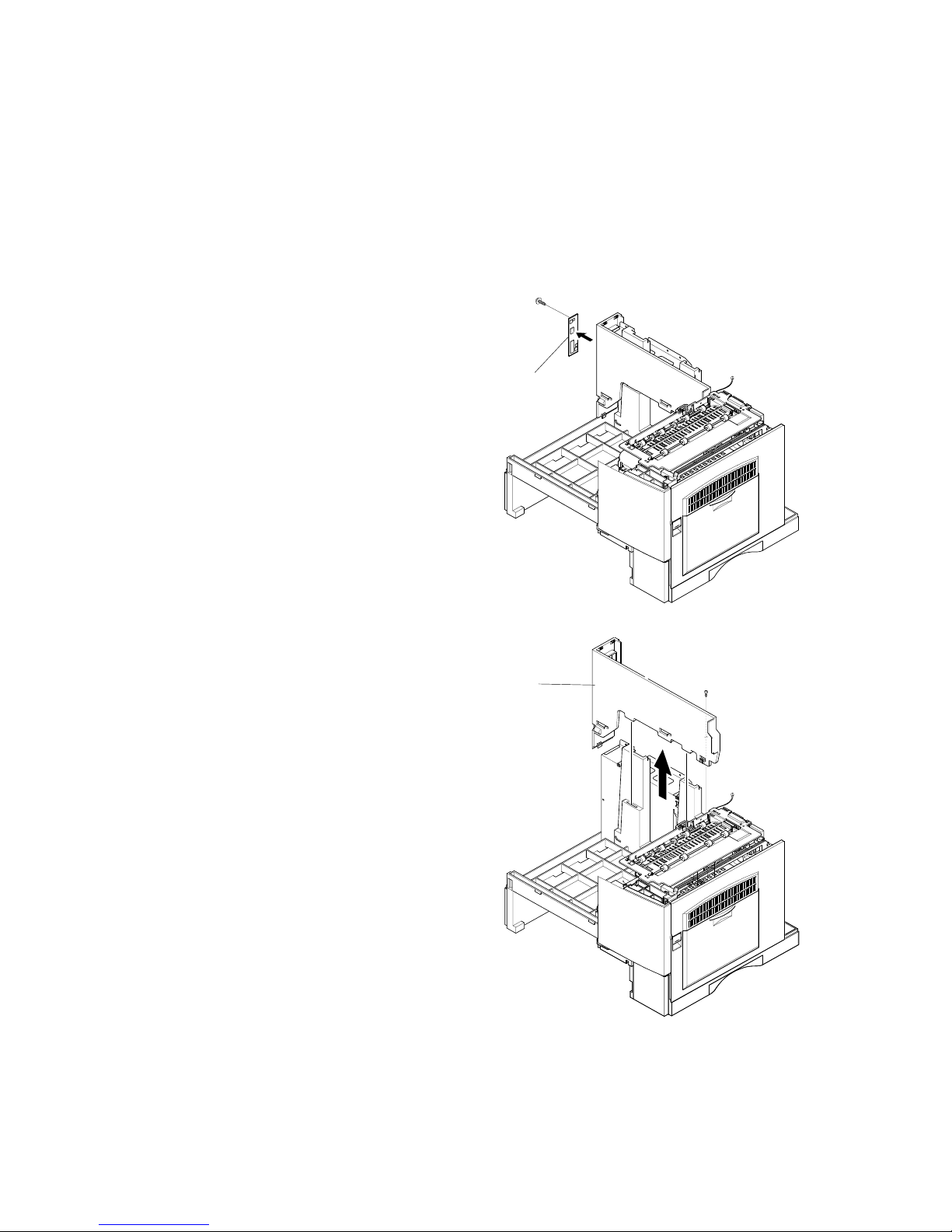
LEFT COVER
B174 3-22 SM
3.13 LEFT COVER
1. Before you remove the Left Cover, you must remove:
- Rear Cover (! 3.2)
- Scanner Ass'y (! 3.3)
- Exit Ass'y (! 3.8)
- Copy Tray (! 3.9)
- SMPS (! 3.11)
2. Remove the Interface Panel [A]
( x 1).
3. Remove the Left Cover [B] ( x 1).
B174R952.WMF
B174R953.WMF
[B]
[A]
Page 57

MAIN FRAME ASS'Y
SM 3-23 B174
Replacement
Adjustment
3.14 MAIN FRAME ASS'Y
1. Before you remove the LSU, you must remove:
- Rear Cover (! 3.2)
- Scanner Ass'y (! 3.3)
- Right Cover Ass'y (! 3.6)
- Fuser (! 3.7)
- Exit Ass'y (! 3.8)
- Copy Tray (! 3.9)
- SMPS (! 3.11)
- LSU (! 3.12)
2. Remove the Dummy Base Frame [A]
( x 5), the Front Cover [B], and the
Paper Exit Cam [C].
3. Remove the Deve Lock Lever [D].
Then remove the Cover Motor
Bracket [E] ( x 1).
B174R954.WMF
B174R955.WMF
[E]
[D]
[A]
[B]
[C]
Page 58
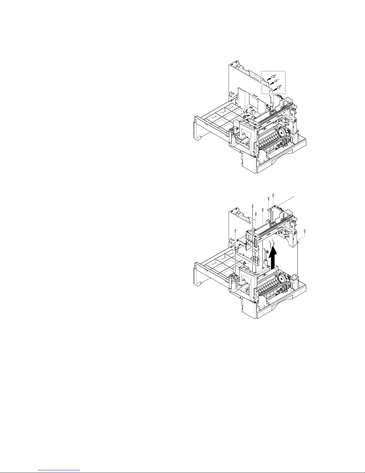
MAIN FRAME ASS'Y
B174 3-24 SM
4. Disconnect all the connectors.
5. Remove the Main Frame Ass'y [A] (
x 7).
B174R956.WMF
B174R957.WMF
[A]
Page 59

MP ASS'Y (MULTI PURPOSE ASS’Y)
SM 3-25 B174
Replacement
Adjustment
3.15 MP ASS'Y (MULTI PURPOSE ASS’Y)
1. Before you remove the MP Ass’y, you must remove:
- Rear Cover (! 3.2)
- Shield Main Upper (! 3.3)
- Right Cover Ass'y (! 3.6)
2. Disconnect two connectors.
3. Remove the Feed Cover [A] ( x 1).
B174R958.WMF
B174R959.WMF
[A]
Page 60
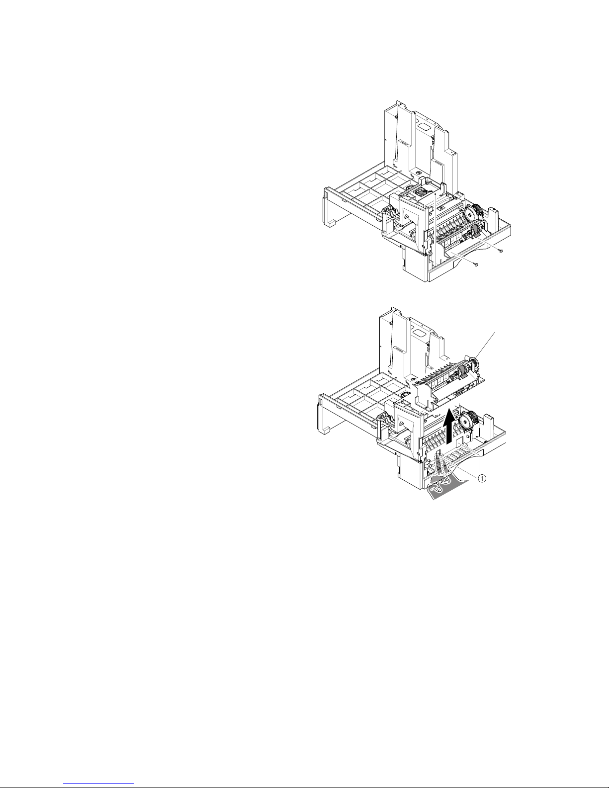
MP ASS'Y (MULTI PURPOSE ASS’Y)
B174 3-26 SM
4. Remove three screws.
5. Release the SMPS by hand from
below, as shown. Pull the MP Ass'y
[A] up and remove it.
B174R960.WMF
B174R961.WMF
[A]
Page 61
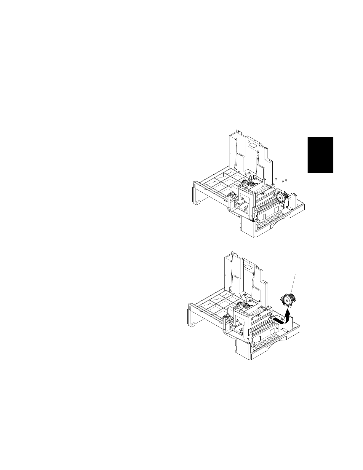
FEED ASS'Y
SM 3-27 B174
Replacement
Adjustment
3.16 FEED ASS'Y
1. Before you remove the Feed Ass’y, you must remove:
- Rear Cover (! 3.2)
- Scanner Ass'y (! 3.3)
- Right Cover Ass'y (! 3.6)
- Exit Ass'y (! 3.8)
- Copy Tray (! 3.9)
- LSU (! 3.12)
- Main Frame Ass’y (! 3.14)
2. Remove three screws.
3. Pull the Feed Ass'y [A] up and
remove it.
B174R962.WMF
B174R963.WMF
[A]
Page 62
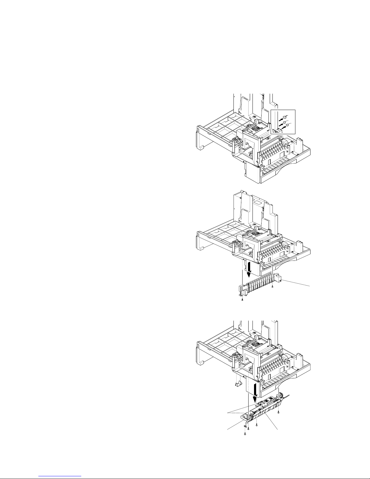
PICK UP ASS'Y
B174 3-28 SM
3.17 PICK UP ASS'Y
1. Before you remove the Pick Up Ass’y, you must remove:
- Rear Cover (! 3.2)
- Shield Main Upper (! 3.3)
- Drive Ass'y (! 3.10)
2. Disconnect three connectors.
3. Remove the Cassette Rail [A] ( x 2).
4. Remove the Pick Up Ass'y [B] ( x 4).
[C]: Rubber – Paper Pick-up (2)
[D]: Quenching (PTL) Lamp
B174R964.WMF
B174R965.WMF
B174R966.WMF
[A]
[B]
[C]
[D]
Page 63
MAIN BOARD
SM 3-29 B174
Replacement
Adjustment
3.18 MAIN BOARD
1. Before you remove the Main Board, you must remove:
- Rear Cover (! 3.2)
- Right Cover Ass'y (! 3.6)
- Copy Tray (! 3.9)
- SMPS (! 3.11)
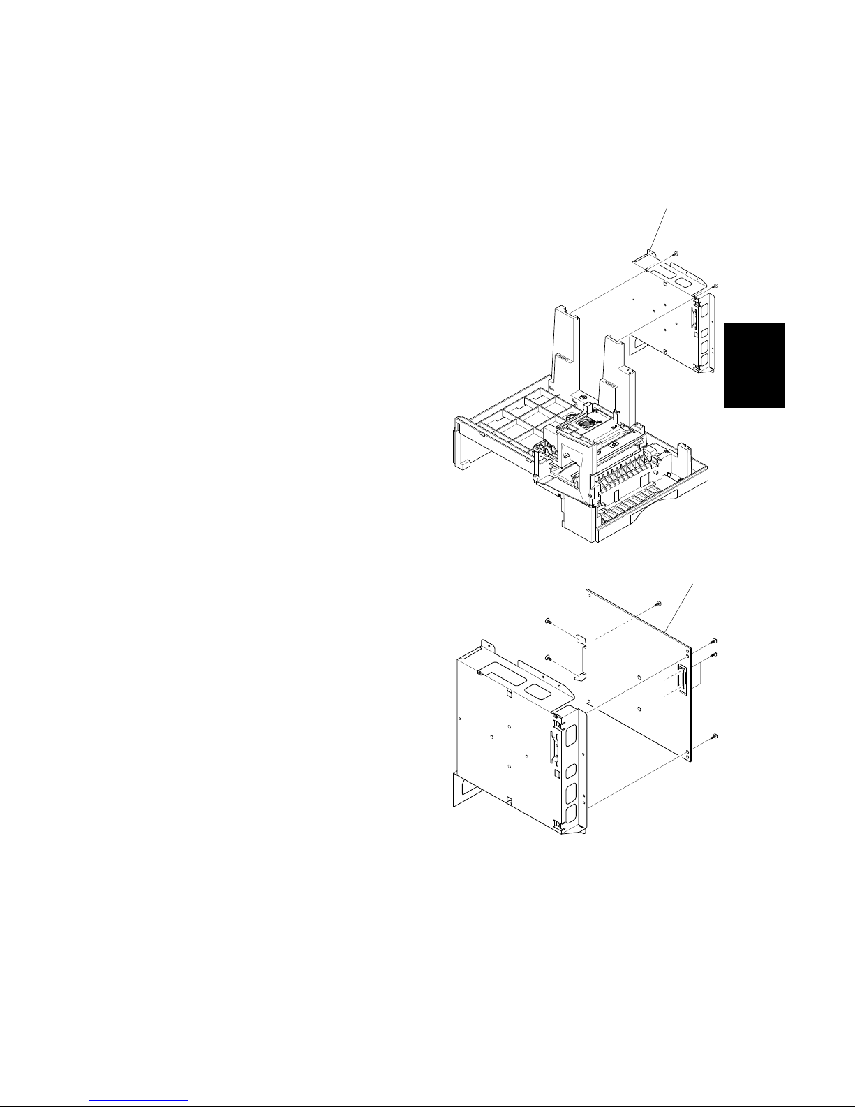
2. Remove the Shield Plate [A] ( x 2).
3. Remove the Main Board [B] from the
Shield Plate ( x 5).
NOTE: Do a memory clear after you replace the main board. If not, the system
possibly will not operate correctly. (! 5.2.4)
B174R967.WMF
B174R968.WMF
[A]
[B]
Page 64

LIU BOARD
B174 3-30 SM
3.19 LIU BOARD
1. Before you remove the LIU Board, you must remove:
- Rear Cover (! 3.2)
- Right Cover Ass'y (! 3.6)
- Copy Tray (! 3.9)
- SMPS (! 3.11)
- Main Board (! 3.18)
2. Remove one screw and unlatch the LIU
Board [A] from the Main Board [B].
B174R969.WMF
[A]
[B]
Page 65

TROUBLESHOOTING
Page 66

Page 67

ERROR MESSAGES
SM 4-1 B174
Trouble-
shooting
4. TROUBLESHOOTING
This chapter includes problem diagnosis and troubleshooting. It shows how to find
and repair print quality problems.
4.1 ERROR MESSAGES
Error Message Description Solution
RETRY REDIAL?
The machine is waiting for the
programmed interval to
automatically redial.
You can press START to
immediately redial, or
STOP to cancel the redial
operation.
COMM. ERROR
A problem with fax communications
has occurred.
Try again.
DOCUMENT JAM
A document has jammed in the
scanner document feeder
Remove the document jam.
DOOR OPEN
The side cover is not correctly
latched
The side door and front
door must be closed in the
correct order. Open both
doors. Close the front door
first, then close the side
door.
GROUP NOT
AVAILABLE
You tried to select a group location
where only a single location
number can be used (for example,
when you add locations for a multidial operation).
Try again. Check the
location for the group.
LINE ERROR
Your unit cannot connect with the
remote machine, or is disconnected
because of a problem on the phone
line.
Usually caused by a
telephone line problem. Try
again. If failure continues,
wait an hour for the line to
clear then try again
LOAD DOCUMENT
You tried to set up a sending
operation with no document in the
feeder.
Insert a document and try
again.
MEMORY FULL The memory is full.
Do one of these:
A. Delete documents that
are not necessary.
B. Transmit again after
more memory becomes
available
C. Divide the transmission
into more than one
operation.
NO ANSWER
The remote machine did not
answer after all the redial attempts.
Try again. Make sure the
remote machine is OK.
Page 68

ERROR MESSAGES
B174 4-2 SM
Error Message Description Solution
NO. NOT ASSIGNED
The speed dial location you tried to
use has no number stored in it.
Dial the number manually
with the keypad, or store
the number.
NO PAPER
[ADD PAPER]
There is no paper in the paper
cassette. Printing stops until paper
is loaded.
Put paper in the paper
cassette.
OVERHEAT The printer has overheated.
Your unit will automatically
return to the standby mode
when it cools down to
normal operating
temperature. If failure
continues, replace the
fusing unit or the main PBA.
PAPER JAM 0
OPEN/CLOSE DOOR
Printing paper is jammed in paper
feeding area or the pick-up unit
Press STOP and remove
the jam.
PAPER JAM 1/2
OPEN/CLOSE DOOR
Printing paper is jammed in the
machine main body or in the paper
exit unit.
Remove the jam.
TONER LOW
The toner cartridge is almost
empty, or toner particles are not
equally applied in the cartridge
Remove the toner cartridge
and carefully rock it from
side to side.
Try again. If problem
continues, replace the
cartridge.
TONER EMPTY The toner cartridge is empty Replace the toner cartridge.
DRUM WARNING The OPC drum is almost at the end
of its life (14,000 sides)
You have 1000 pages of
print life left in the OPC
Drum. Continue to use, or
install a new OPC drum.
REPLACE DRUM The OPC drum life is expired
(15,000 sides)
Replace the OPC drum
cartridge.
NO CARTRIDGE A toner cartridge is not installed. Install the cartridge.
BYPASS JAM Paper feed problem from the
bypass (Manual feed) Tray.
Open the side cover and
remove the jam.
DUPLEX JAM Paper feed problem in the duplex
return path
Release the output feed
lever and check the output
area. Also, open the side
door and check the duplex
unit.
LINE BUSY The remote fax didn’t answer Try again.
OPEN HEAT ERROR No power to the fusing lamp Check the thermostat,
thermistor, fuser lamp and
fuser connector and related
wiring. Also check the
‘Fuser On’ signal from main
PWA to Power Supply.
Check the cable from Main
PWA to Power Supply
Page 69
ABNORMAL IMAGE PRINTING AND DEFECTIVE ROLLERS
SM 4-3 B174
Trouble-
shooting
Error Message Description Solution
Heating Error During operation, Temperature
does not go up
Check the thermistor
contact point & the fusing
lamp.
Scanner Locked Scanner head does not move. Check the transit lock.
Check that the scanner
cables are connected.
Check the scanner home
sensor, scanner motor or
drive belt.
4.2 ABNORMAL IMAGE PRINTING AND DEFECTIVE
ROLLERS
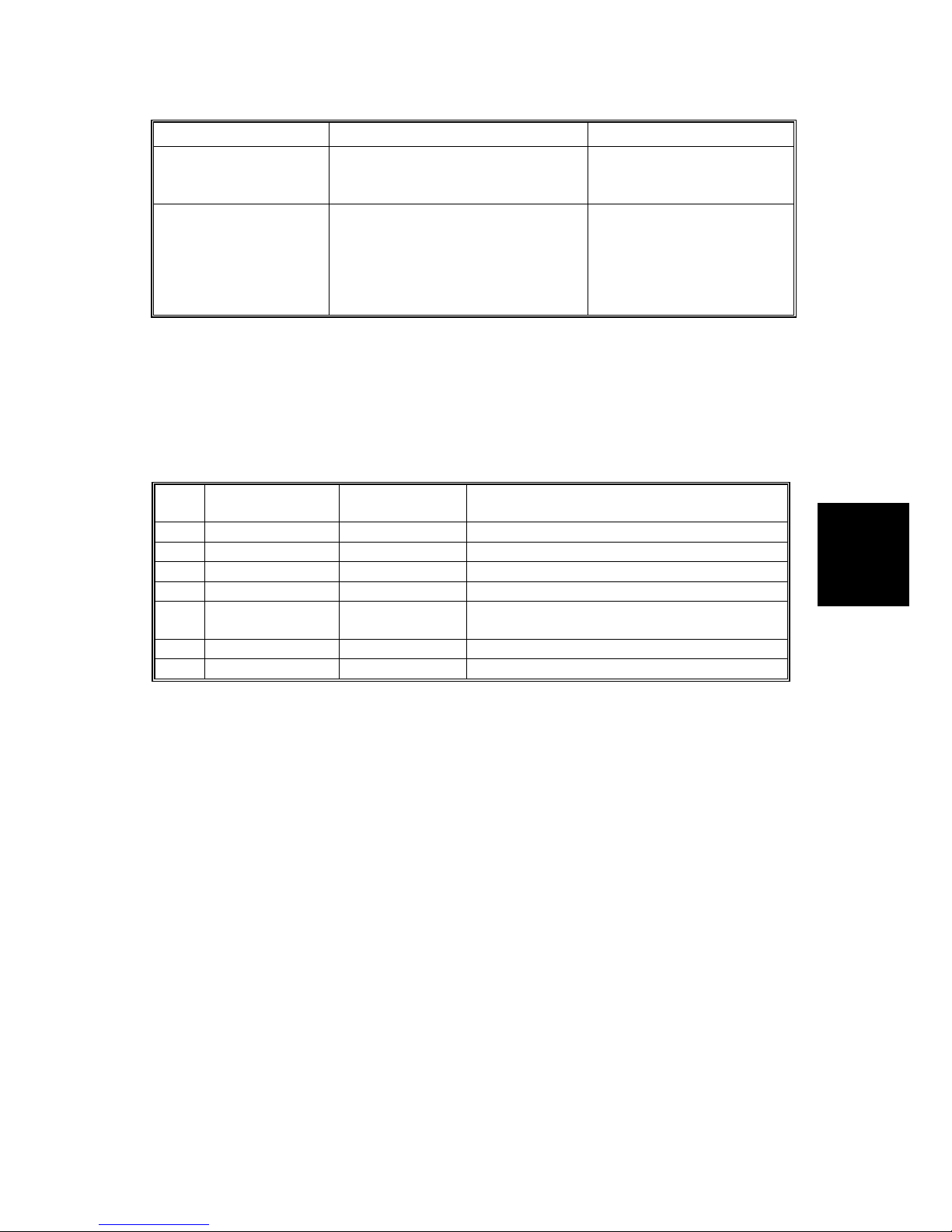
If an abnormal image occurs at regular intervals, check the parts shown below.
NO Roller
Abnormal
image period
Kind of abnormal image
1 OPC Drum 94.3 mm White spot. Black spot
2 Charge Roller 37.7 mm White spot. Black spot
3 Supply Roller 35.8 mm Horizontal dark band
4 Develop Roller 44.8 mm Horizontal dark band
5 Transfer Roller 57.8 mm
Contamination on reverse side of paper /
transfer fault
6 Hot Roller 82.5 mm Black spot, White spot
7 Pressure Roller 78.5 mm Contamination on reverse side of paper
Page 70

TROUBLESHOOTING
B174 4-4 SM
4.3 TROUBLESHOOTING
4.3.1 SCANNER
COPY
Problem Items to be checked How to solve
• Make sure that the scanner
cover is closed.
• Room lighting can go through
thin paper. This causes quality
problems
White copy
• Check the shading profile • Do the “Adjust Shading”
procedure in Tech mode
• Check the CCD problem in
Main PBA.
• Check the CCD harness
contact.
Black copy
• Check shading profile. • Do the “Adjust Shading”
procedure in Tech mode.
• Check shading profile. • Do the “Adjust Shading”
procedure in Tech mode
• Check the original is lying flat
on the scanner glass.
• A gap above 0.5 mm can
cause a blurred image.
Defective image
quality
• Check the printing quality. • See “Print” troubleshooting.
• Check the scanner drive
mechanism.
• Check for mechanical
problems in the scanner
carriage, motor, gearbox, belt
and belt tension spring.
• Make sure that the scanner
motor position is correct.
Abnormal noise
• Check the Motor Driver chip on
the Main PBA.
• If a driver is defective, replace
the Main PBA.
Page 71

TROUBLESHOOTING
SM 4-5 B174
Trouble-
shooting
PC-SCAN
Problem Items to be Checked. How to Solve
• Check the printer cable is correctly
installed.
• Use a standard IEEE1284
cable.
• Check that the TWAIN driver is
installed.
• Remove all other scanner
drivers.
• Reboot after you reinstall the
TWAIN driver.
• Check the printer port (Parallel) BIOS
settings.
• Check the parallel port
related items in the CMOS
Setup. For a printer port,
make sure that ECP is
selected.
• Check the harness connection. • Check CN12 connection on
the Main PBA
• Check the IEEE1284 signal levels. • If a signal level is defective,
replace the Main PBA.
Scanning
Error
• Check the USB signal level. • If the USB signal level is
defective, replace the Main
PBA.
• Check shading profile. • Do the “Adjust Shading”
procedure in Tech mode.
Defective
image Quality
• Check the gap between original and
scanner glass.
• A gap above 0.5 mm can
cause a blurred image.
• Check the Scanner Motor and
mechanical problems in the scanner.
• Check for mechanical
problems in the scanner
carriage, motor, gearbox,
belt and belt tension spring.
• Make sure that the scanner
motor position is correct.
Abnormal
noise
• Check the motor driver in the Main
PBA.
• If a driver is defective,
replace the Main PBA.
Page 72

TROUBLESHOOTING
B174 4-6 SM
4.3.2 FAX
FAX/TELEPHONE PRECAUTIONS
Problem Items to be Checked. How to Solve
TEL LINE CANNOT
BE ENGAGED (NO
DIAL TONE)
• When you press the “OHD” key:
a) Check the line cord connection.
b) Check the MAIN LIU harness,
and CN1
(LIU PBA).
c) Check the relay operation of the
LIU PBA: Is the control signal of
CN18 (main) low?
a) Insert it correctly into the
connection jack called
“Line”.
b) Replace defective parts.
c) Replace the main PBA
IF the control signal of
N18 (main) is high.
Replace the LIU PBA if high
but the phone line cannot
be connected.
Tone dial is not
possible
• Check CN18 (main PBA), MAINLIU harness, and CN1 (LIU PBA)
• Replace defective parts.
Tone dial is possible
but not pulse dial
• Check DP control signal of CN1811 of MAIN PBA and the circuit
around R15. U6 and Q2 of Liu
PBA.
• Replace the LIU PBA.
Defective fax
transmission
• Check CN18 (main PBA), MAIN
LIU harness, and CN1 (LIU PBA).
• Is the external phone off hook?
• Check ‘hook off’ : Refer to ‘TEL
LINE CANNOT BE ENGAGED’
above.
• Check the transmission path:
Check output of CN20-3.4 and
T2-4(LIU PBA).
• Check the reception path: Check
output CN1-1 (LIU PBA) and input
of CN18-1 (main PBA).
• Replace defective parts.
• Replace the LIU PBA if
low.
• Refer to ‘TEL LINE
CANNOT BE ENGAGED’
above.
• Replace the main PBA, if
abnormal.
• Replace the LIU PBA if
CN1-1(LIU PBA) is not
confirmed.
• Replace the main PBA if
CN20-1(MAIN PBA) is
not confirmed.
Defective automatic
fax reception
• Is the ring detected?
Check the ring signal at CN1-9
(LIU PBA).
• Refer to ‘“Defective
Transmission”.
• Replace the LIU PBA if it
cannot be checked.
• Refer to “Defective
Transmission”.
Page 73
TROUBLESHOOTING
SM 4-7 B174
Trouble-
shooting
4.3.3 PRINT QUALITY
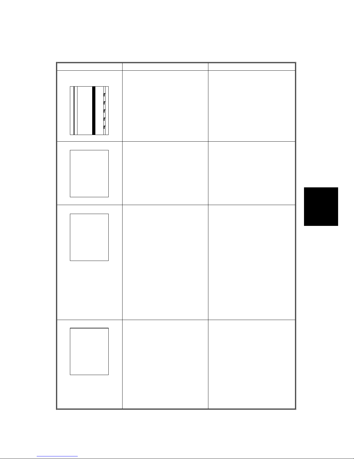
Error Status Check Solution
Vertical black line
and band
Digital Printer
Digital Printer
Digital Printer
Digital Printer
Digital Printer
1. Faulty toner cartridge
2. LSU
1. Change the toner cartridge
2. Replace LSU
Vertical white line
Digital Printer
Digital Printer
Digital Printer
Digital Printer
Digital Printer
B174T921.WMF
1. LSU window dirty
2. Toner cartridge
1. Clean the LSU window
2. If not the LSU, change the
toner cartridge.
No image
Digital Printer
Digital Printer
Digital Printer
Digital Printer
Digital Printer
B174T922.WMF
1. Is the seal tape removed?
2. OPC is properly
grounded?
3. LSU running well?
4. Toner low?
5. Is there video data from
the Main PBA?
1. Check and remove tape
2. Measure the resistance
between frame ground and
the OPC ground spring
attached to the frame.
Confirm good ground. If
faulty, check the ground
path through the frame.
3. Replace the LSU
4. Shake the toner cartridge
and print. If an image
appears, the toner cartridge
is empty
5. Print the engine test
pattern. If no pattern is
printed, replace the Main
PBA.
Light image
Digital Printer
Digital Printer
Digital Printer
Digital Printer
Digital Printer
B174T923.WMF
1. Is the seal tape removed?
2. LSU light power normal?
3. Enough toner?
4. High charger voltage?
5. Lower bias voltage
6. Transfer voltage and roller.
7. Contamination of high
voltage contact.
1. Check and remove tape
2. Checking LSU light power
is difficult. Compare with a
new one.
3. Check the toner counter
4~6. Change the HVPS (SMPS)
Board.
6. Clean or replace the transfer
roller.
7. Stray toner can increase
contact resistance and cause
a bad contact. Clean the
contaminated area.
Page 74

TROUBLESHOOTING
B174 4-8 SM
Error Status Check Solution
Dark image
Digital Printer
Digital Printer
Digital Printer
Digital Printer
Digital Printer
B174T924.WMF
1. LSU light power normal?
2. Video data is always
supplied?
1. Checking LSU light power
is difficult. Compare with a
new one.
2. Replace defective board(s)
Background
Digital Printer
Digital Printer
Digital Printer
Digital Printer
Digital Printer
B174T925.WMF
1. High voltage output is
normal?
2. C/R of toner cartridge is
dirty?
1. Change the HVPS (SMPS)
Board.
2. Replace the toner cartridge.
Ghost
Digital Printer
Digital Printer
Digital Printer
Digital Printer
Digital Printer
Digital Printer
B174T926.WMF
1. High voltage output.
2. Quenching Lamp.
3. Bad high voltage contact.
1. Change the HVPS Board.
2. Check the quenching lamp
comes on – replace the
quenching lamp if
necessary.
3. Clean inside the machine
or replace the toner
cartridge.
Stains on back of
paper
1. Dirty transfer roller.
2. Toner debris in the paper
path
3. Pressure roller dirty
1. Clean the transfer roller
with a vacuum cleaner.
2. Clean the paper path with a
cloth or air brush.
3. Replace the fusing unit
Poor Fusing
1. Paper quality and finish?
2. Check the fusing unit
temperature.
3. The machine was kept at a
low temperature for a long
time?
1. Should use recommended
paper.
2. Measure the thermistor
voltage to the Main PBA. It
is 2.3V±5% when printing is
correct. If not, replace the
fusing unit.
3. Re-check after you let the
machine come up to room
temperature.
Partial blank image
(not periodic)
1. Toner is low?
2. The toner cartridge is out
of position?
1. Replace the toner cartridge.
2. Check and adjust.
Page 75
TROUBLESHOOTING
SM 4-9 B174
Trouble-
shooting
Error Status Check Solution
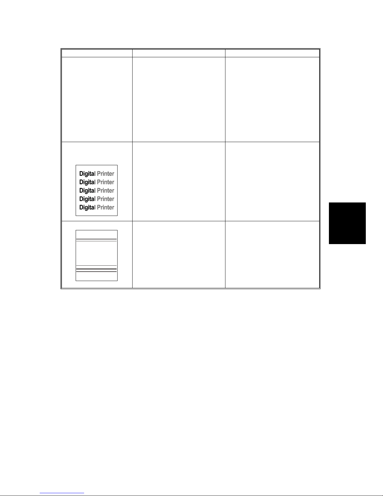
Partial blank image
(periodic)
1. Developer roller scar or
particle. (45 mm)
2. OPC scar or particle. (95
mm)
3. Transfer roller scar or
particle. (58 mm)
1. Replace the toner cartridge.
2. Replace the drum cartridge.
3. Replace the transfer roller.
Different image
density (left and
right)
B174T929.WMF
1. Charge roller’s pressure not
balanced
2. Dev. roller and OPC or Dev.
roller and blade’s pressure
not balanced
3. Transfer roller’s pressure
not balanced on each side
1. Replace the drum cartridge.
2. Replace the drum and/or
toner cartridge.
3. Check the left and right
springs of the transfer roller
and the spring that pushes
the development unit inside
the machine
Horizontal band
Digital Printer
Digital Printer
Digital Printer
Digital Printer
Digital Printer
B174T928A.WMF
1. Unstable high voltage
contact
2. .Charge roller dirty
3. .Dirty hot roller
4. Malfunction of LSU
1. Clean each contact and
check good contact
2. Clean the charge roller.
3. Replace the fusing unit
4. Check the Main PBA
Page 76
TROUBLESHOOTING
B174 4-10 SM
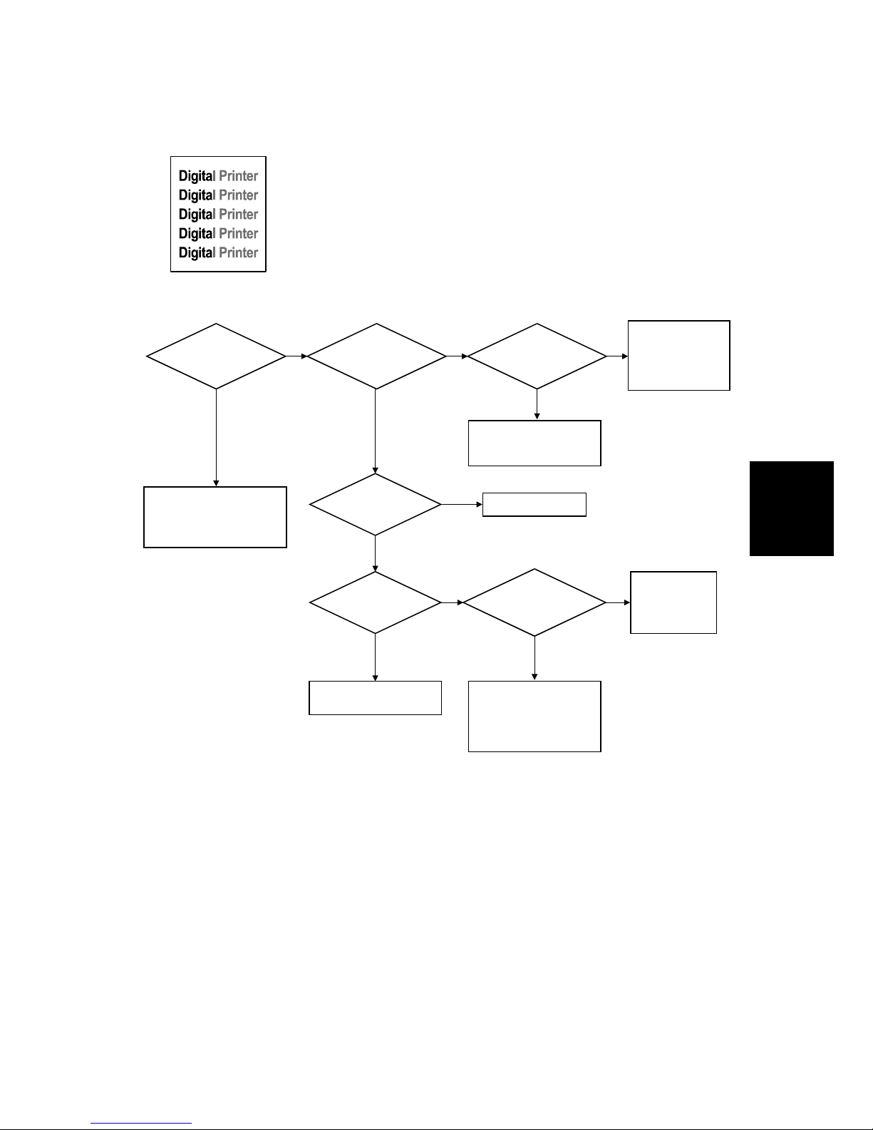
No Image
Digital Printer
Digital Printer
Digital Printer
Digital Printer
Digital Printer
B174T922.WMF
No Image?
Self testing
is possible ?
Self test
pattern prints?
Is the OPC
terminal of machine
correctly connected
to the frame?
Does the
video data line to
LSU change High/Low
when printing?
Retest after replacing the
connector or main board
Check connection to
computer or replace
main board
Take out the cartridge and
prepare the tester for
electronic connection
Repair or replace the
GND terminal
Check the path between
main board and HVPS.
Replace the defective
board
The mirror in the LSU might
be misplaced, so the light
path to the OPC deviates Replace the LSU or remove
defective parts in the
machine
A on next
page
No
No No
Yes Yes
No
No
Yes
Yes
Yes
B174T901.WMF
Page 77

TROUBLESHOOTING
SM 4-11 B174
Trouble-
shooting
Is the connection
terminal OK?
Repair or replace terminal
Replace the toner cartridge
Replace the HVPS
The transfer roller might be out of its location
→ Put the roller into its correct place
The power of the LSU might be low or the light
intensity is low due to dirt on the window
→ Replace the LSU or clean the window
No
No
Yes
Transfer
voltage OK? (on the
transfer roller
shaft)
Are the connection
terminal and connection
correct?
Dev. roller
(-300V) and toner supply
(-450V) voltages
are OK?
Repair or replace terminal
Replace the HVPS
Is the toner
cartridge life expired (see
the counter)?
No
Yes
No
Yes
No
Yes
Yes
A
B174T902.WMF
Page 78
TROUBLESHOOTING
B174 4-12 SM
All Black
Digital Printer
Digital Printer
Digital Printer
Digital Printer
Digital Printer
B174T924.WMF
Is charge
voltage supplied
from HVPS?
The charge terminal
contact is bad
→ Replace the drum
cartridge
Check the path between
video controller, engine
board, HVPS, LSU for a
short or open circuit
→ Replace the defective
board or wiring
No
Yes
Does the
video data line to LSU
change High/Low when
printing?
No
Yes
All black in
printing area?
Is the Hsync/
signal received in
LSU?
Yes
No
No
Yes
Replace the HVPS
Replace the LSU
Replace the LSU
B174T903.WMF
Page 79
TROUBLESHOOTING
SM 4-13 B174
Trouble-
shooting
Vertical White Line (Band)
Digital Printer
Digital Printer
Digital Printer
Digital Printer
Digital Printer
B174T921.WMF
Ribs in the fusing unit or
toner on the roller may
cause this problem
-> Replace the fusing unit
or the defective part
The image is originally
black or the black part is
too close to the top of the
page
→ Print an image that
has black more than 10
mm from the top
Dirt or dust stuck on the
window of the internal lens of
the LSU
→ Clean it or replace the LSU
Obstacles between OPC or
developer and LSU
→ Remove the obstacles
No
Yes
Check
if the printout
has the same problem just
after it passed
the transfer roller
No
White line missing
definitely?
Yes
Toner might be stuck to the
toner metering blade and this
prevents toner supply
→ Replace the toner
cartridge
Check if the toner cartridge
counter is over its guaranteed
life and check the amount of
remaining toner
→ Replace the toner
cartridge
B174T904.WMF
Page 80
TROUBLESHOOTING
B174 4-14 SM
Dark Image
Digital Printer
Digital Printer
Digital Printer
Digital Printer
Digital Printer
B174T924.WMF
Works correctly
with -300V of bias
voltage?
The power of the LSU is
too high or there is an
internal problem
→ Replace the LSU
No
Yes
Dark selected via
Remote Control
Panel?
Works correctly
after replaced
LSU?
Yes
No
No
Toner over-supply due to
incorrect adjustment of metering
blade
→ Replace the toner cartridge
Replace the defective
component
Change to Normal and test
Same at Normal?
Yes
END
No
Yes
Yes
B174T905.WMF
Page 81
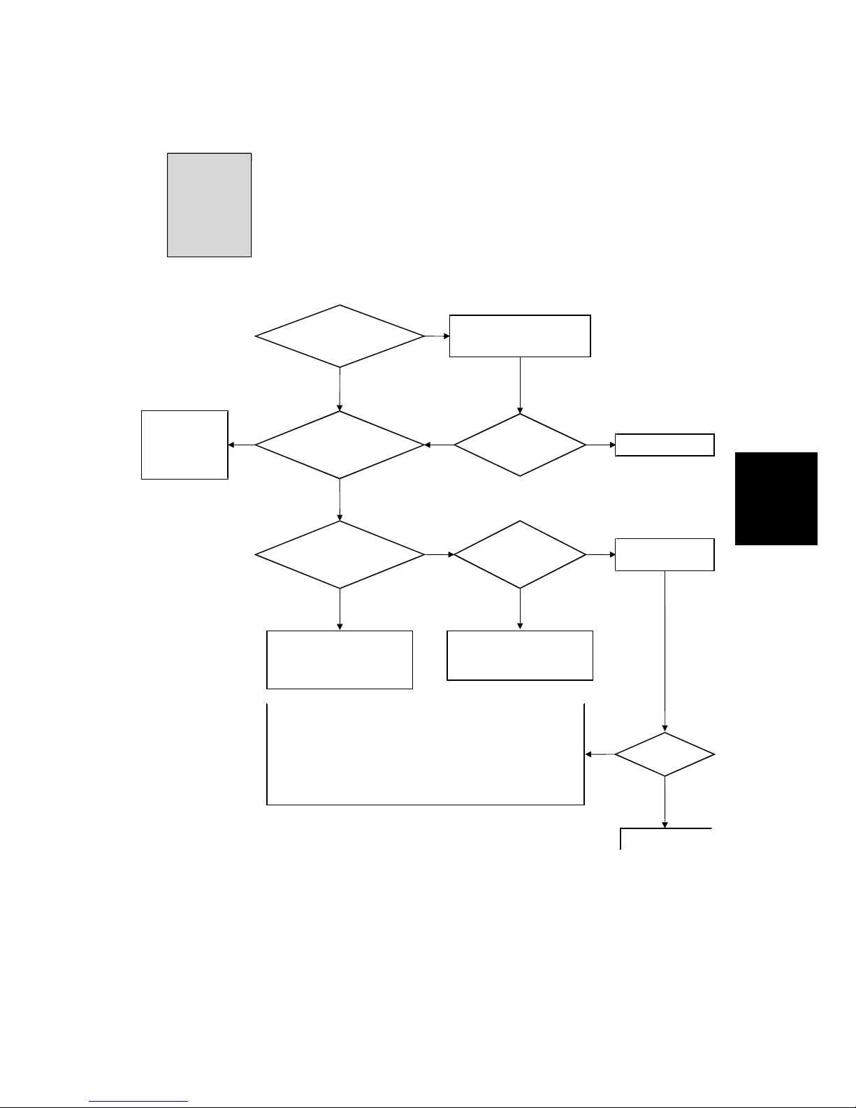
TROUBLESHOOTING
SM 4-15 B174
Trouble-
shooting
Background
Digital Printer
Digital Printer
Digital Printer
Digital Printer
Digital Printer
B174T925.WMF
Solve the problem under
the recommended
operating condition
(10-32 degrees Centigrade)
Yes
Recommended paper
used?
No
Clean the charge roller or
replace the drum cartridge
Yes
Yes
Yes
Dirt or
dust around the
charge roller?
Same problem
occurs?
Print 20 to 30 pages using
recommended paper
Check that each terminal or contact are in the correct posiiton
and not dirty.
→
Repair or replace components.
Check if the LED of the quenching lamp in the pick up ass'y is
on when you push the top cover switch
→
If not, replace the quenching lamp.
Replace HVPS
after checking
the terminals'
contacts
Replace the
toner cartridge
Works OK?
END
Operating/
storage atmosphere is too
hot/humid?
Transfer,
charge and developing
voltage are OK?
Yes
END
No
No
No
No
Yes
No
B174T906.WMF
Page 82
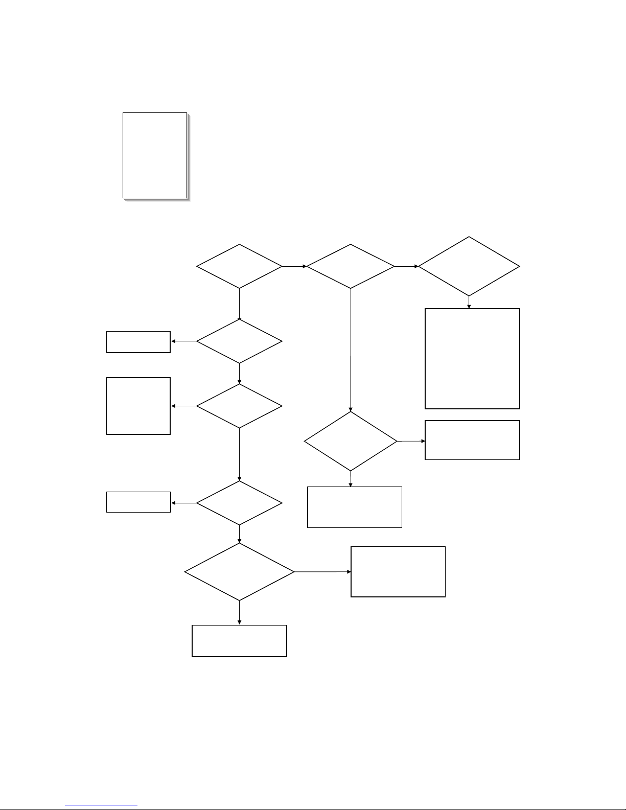
TROUBLESHOOTING
B174 4-16 SM
Ghost
Digital Printer
Digital Printer
Digital Printer
Digital Printer
Digital Printer
Digital Printer
B174T926.WMF
Irregularity of the nip
between rollers in the toner
cartridge → Replace the
toner cartridge
Use the machine with
recommended paper and
conditions
Is it at a regular
interval of 95mm?
There may be a problem
with toner layer control in
the toner cartridge
→ Replace the toner
cartridge
Is it at a regular
interval of 45mm?
Check the HVPS
contacts and HVPS
output test mode
(see section 5-6)
→
If failed, replace
the HVPS
Yes
No
Dev. roller/
supply roller voltages
OK?
(-300V/-450V)
PTL
(Quenching) lamp
works OK?
Bias voltage is OK?
(-300V)
Operating/
storage temperature is too
low or not recommended
paper used?
Replace the PTL
assembly
Is it at a regular
interval
of 58 mm? (transfer
roller interval)
A specific part of the
transfer roller is damaged
or its resistance is changed
→ Replace the transfer
roller
The transfer roller cannot
turn correctly due to
eccentricity of the transfer
roller gears
→ Replace the defective
component
! Replace the HVPS
! Check and repair or
replace the terminal
contacts
Replace the
HVPS
Transfer voltage is
set to standard?
Yes
No
No
Yes
Yes
Yes
No
No
Yes
No
Yes
No
Yes
B174T907.WMF
Page 83
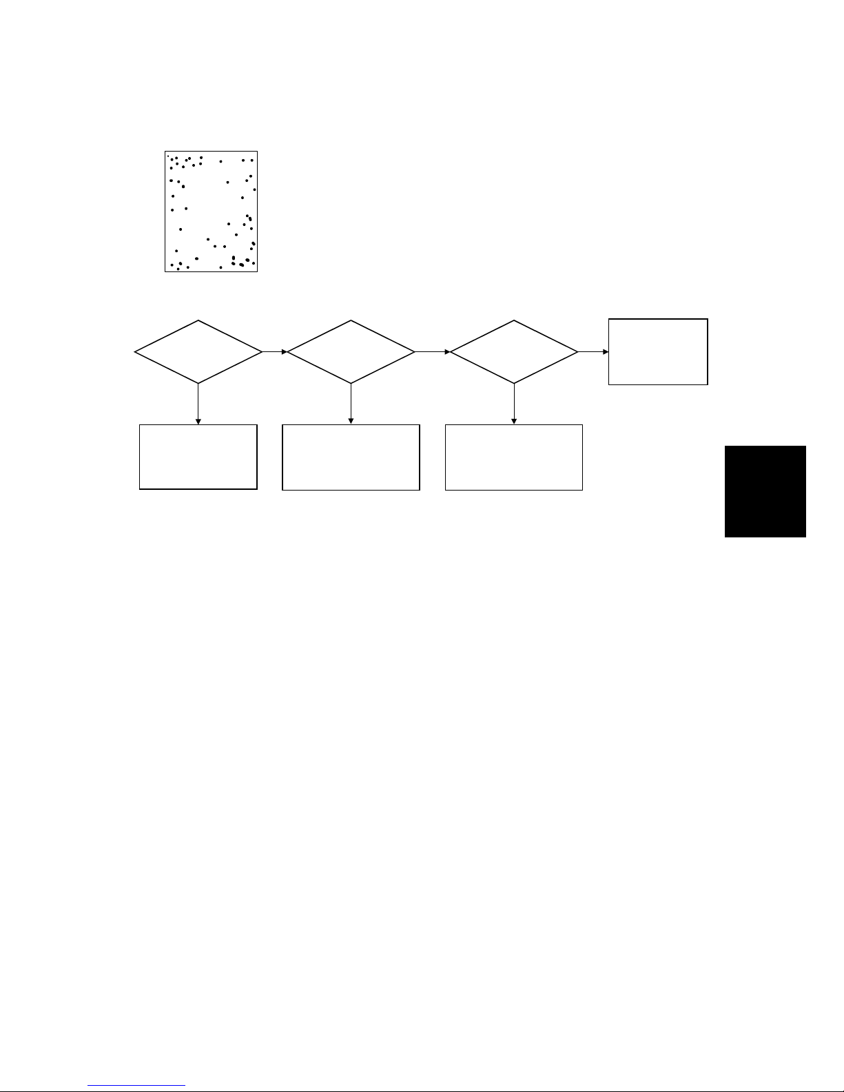
TROUBLESHOOTING
SM 4-17 B174
Trouble-
shooting
Black Spot
Digital Printer
Digital Printer
Digital Printer
Digital Printer
Digital Printer
B174T927.WMF
When taking
out the cartridge,
toner leaks?
Foreign objetcs stuck
to the charge roller
→ Clean the charge
roller.
Bad image
removed by
scratching?
Yes
No
The problem
randomly occurred
due to falling toner
→ Clean the
machine
No
Yes
Is it a regular
interval of 38 mm?
Toner leaks and a lot of
toner dropped onto the
paper
→ Replace the toner
cartridge
Check if toner is stuck onto
the pressure roller or hot
roller in the fusing unit
→ Clean or replace the
fusing unit
Yes
No
B174T908.WMF
Page 84
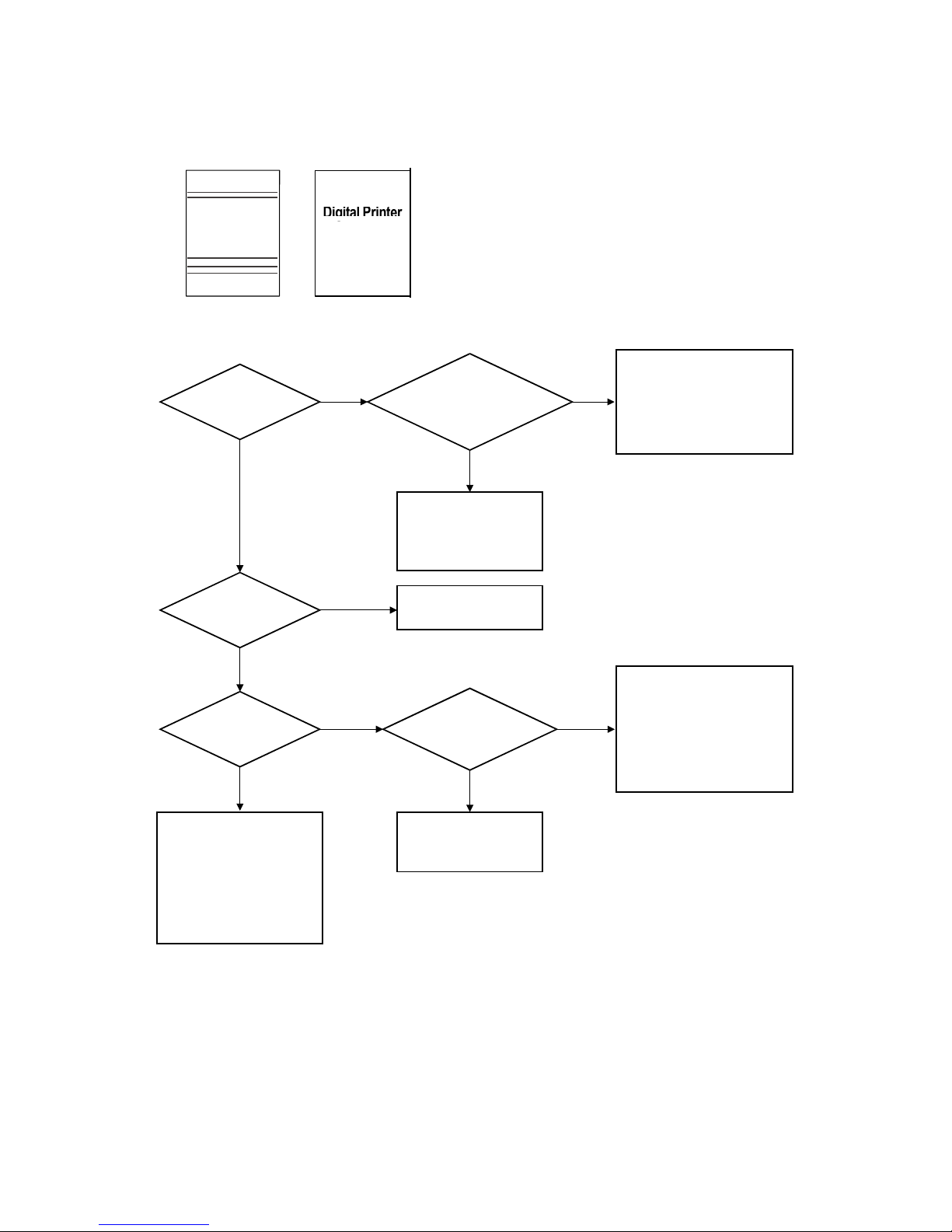
TROUBLESHOOTING
B174 4-18 SM
Horizontal Band
Digital Printer
Digital Printer
Digital Printer
Digital Printer
Digital Printer
B174T928A.WMF
Digital Printer
Digital Printer
Digital Printer
Digital Printer
Digital Printer
B174T928B.WMF
The black
band has a regular
interval?
The OPC is damaged
due to incorrect transfer
voltage from the HVPS
→ Replace the HVPS
→ If the same problem
persists, replace the
drum cartridge
The OPC is damaged
under direct sunlight for
around 5 minutes
→ If the same problem
persists after 10 hours,
replace the drum cartridge
No
Yes
Black band is
about 95mm from white
band?
No
Yes
Black band?
95 mm interval?
Yes
No
No
Yes
Problem with internal
contacts in the OPC
→ Replace the drum
cartridge
No Hsync/ at the LSU
→ Replace the LSU
Every 83mm
at a specific
place?
Problems of terminal
contact, transfer voltage
supply, and transfer roller
because the charge roller is
defective (38 mm)
→ Replace the HVPS and/
or drum cartridge
Hot roller defective
→ Replace the fusing
unit
No
Yes
B174T909.WMF
Page 85
TROUBLESHOOTING
SM 4-19 B174
Trouble-
shooting
Irregular Density
B174T929.WMF
OK after
taking out and rocking
the toner
cartridge?
Any dust
on the PTL lamp?
Bad images
around no-image
areas?
Check the high voltage
output and repair/
replace terminals, HVPS
No
PTL lamp
(Quenching lamp)
works OK?
Replace the lamp
Light distortion due to a
defective mirror or
diffused reflection from
the LSU
→ Replace the LSU
Clean the window of the
PTL
The guaranteed life of the
toner cartridge is over
(Check the counter and
replace it)
Defective agitator
in the toner supply
mechanism
→ Replace the
toner cartridge
Irregular toner
supply
→ Replace the
toner cartridge
When
printing a gray pattern,
irregular density
persists?
Transfer/
charge/development
voltage drops while
printing?
No No
Yes Yes
Yes
No
Yes
No
Yes
Yes
No
B174T910.WMF
Page 86

TROUBLESHOOTING
B174 4-20 SM
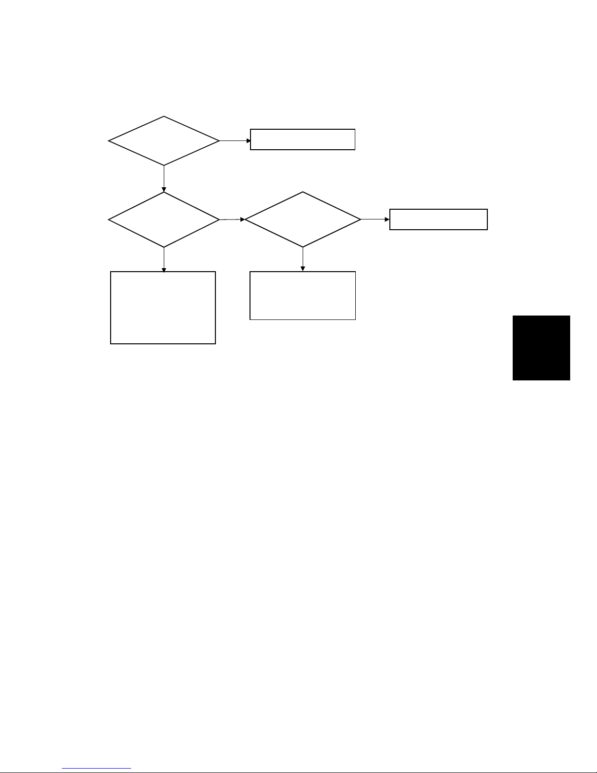
White Spot
Digital Printer
Digital Printer
Digital Printer
Digital Printer
Digital Printer
B174T930.WMF
Transfer
voltage is normal?
Dirt on the OPC surface
→ Clean the OPC and the
machine, or replace the
drum cartridge
When installing or removing
the drum cartridge, a scratch
was made
→ Replace the cartridge
Yes
No
Is it at a regular
interval of 95 mm?
Development roller defective
→ Replace the toner
cartridge
Too much voltage supplied
due to a setting error for the
transfer voltage
→ Replace the HVPS
Yes
No
B174T911.WMF
Page 87
TROUBLESHOOTING
SM 4-21 B174
Trouble-
shooting
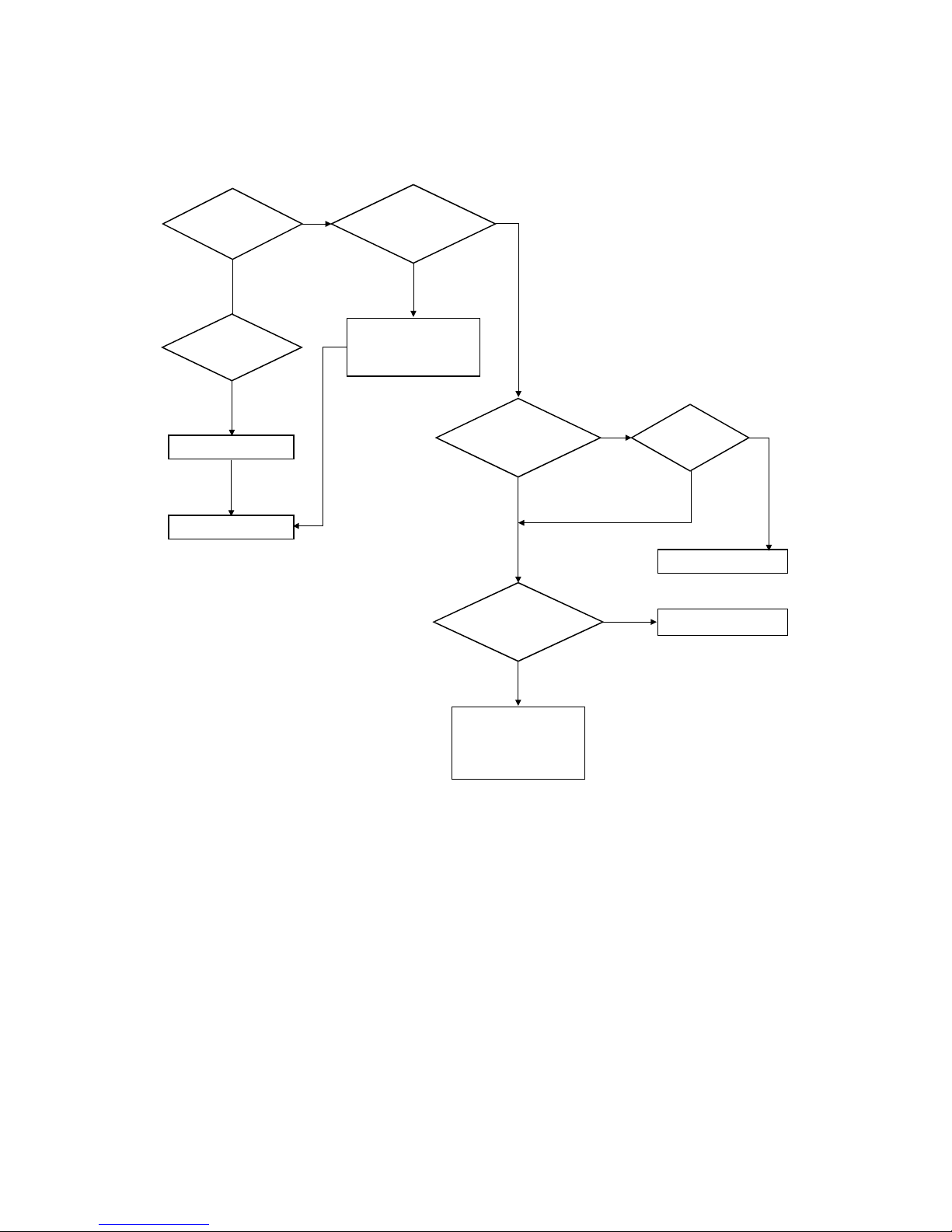
Trembling at the End When OHP Printing
Inserted more
than 10 films into
the MPF?
When multi-page OHP
printng, less than 10
films are guaranteed.
(Reduce the number of
films and re-insert after
paper check LED is off)
No
Yes
Yes
Recommended
OHP film used?
No
Use recommended film
Other parts touch the fan
and prevent it from
turning
→ Check and repair
When OHP
printing, does the fan
stop and start?
Yes
Use recommended film
B174T912.WMF
Page 88
TROUBLESHOOTING
B174 4-22 SM
Poor Fusing Grade
After printing
completed, any error
related to fusing?
The paper used is too
thick or contains too
much cotton
→ Re-test with
recommended paper
Replace the fusing unit
Was the machine
stored in a very low
low temperature for
a long time?
No
Yes
Yes
Yes
No
Thermistor's
contact is OK?
Both ends
of the thermostat
open?
Place the machine at
normal temperature and
re-test
Replace the fusing unit
Replace the Main PBA
Replace the fusing unit
While printing,
the voltage at pin 60 of U36
(CPU) on the Main PBA is
2.1V - 2.6V?
Open the top
cover. When black printing,
is the fusing nip width
3.0 - 3.5 mm?
Yes
No
No
Yes
Yes
Yes
No
No
B174T913.WMF
Page 89

TROUBLESHOOTING
SM 4-23 B174
Trouble-
shooting
4.3.4 MALFUNCTION
Error
Status
Check Solution
No power
1. Check the supplied
power
2. Check if fuse F1 on the
SMPS is open
1. If the supplied power differs from
machine’s power rating, replace the
machine to the correct type for your
area.
2. Replace SMPS.
Fuser Error
1. Thermostat open
2. AC wire open
3. Thermistor wire open
4. Main PBA
1. Detach the AC connector and measure
the resistance between pin 1 and 2. If it
is mega-ohm, the thermostat is open,
Replace it.
2. Check if there is a bad connector
contact or if the wire is cut.
3. Check the thermistor wire and its
connection.
4. Replace the Main PBA
Cover open
1. When you close the side
cover, check that the
lever is pressed
2. Microswitch contact
3. CPU and related circuit
1. Open the side cover and press the lever
with a pen. If the machine detects that
the cover is closed, there is a
mechanical problem with the side cover
and lever assembly. If not, there is an
electrical problem.
2. Check and replace the microswitch
3. Check and replace the main PBA
Jam 0 Check where Jam 0 occurs
1. Paper is not picked up
2. Paper is at the feed
sensor
3. Occurred when inserting
specific types of paper
such as envelopes into
the bypass tray?
4. Is the Stacker Extender
folded out?
5. Does the guide bend the
sheets?
1. Check whether the solenoid is working or
not by using Engine test mode
2. Check for a feed sensor malfunction.
3. Re-try inserting fewer sheets.
• Fan the sheets and align them
• Take out the loaded sheets and insert
them in the reverse direction
Take out the loaded sheets and insert
them in the reverse direction
• Inserted sheets as recommended for
Manual Feeding?
• When loading, tap the sheets until the
paper sensor detects them in the tray
4. When using long paper, use the Stacker
Extender
5. Adjust the guide to fit the paper width
Page 90

TROUBLESHOOTING
B174 4-24 SM
Error
Status
Check Solution
Jam 1
Paper is stopped just after
the fusing unit.
1. It is mostly caused by double feeding.
Check that paper is stocked correctly in
the feeder.
2. Check the feed actuator position and
actuator’s operation. There may be stiff
moving or double reflection. If not, check
the operation of the feed sensor with
Engine test mode.
3. Check the exit lever operation. Remove
the jam and check the actuator motion by
hand. If the actuator is too stiff, paper is
wrapped around the heat roller. Remove
obstacles or replace.
Jam 2 Check where Jam 2 occurs
1. Paper is curled and
cannot exit.
2. Paper is curled in the exit
cover.
1. Remove paper and check if the hot roller
strippers are defective. Clean the fusing
unit.
2. Check that the lock works well. Watch
whether the ribs of the exit cover have a
burr or resistive edge. If they do, remove
obstacles or replace.
Jam 2 at
face-down
tray
1. The paper is not drawn in
because of the stack of
papers in the exit tray.
2. Does it curl while coming
out?
1. Load the recommended quantity of paper
2. Open the Front Cover and check whether
a roller or spring, which is related to
paper exit, is not out of position. If so, re-
locate or replace
.
Clutch error
1. Check the spring of the
solenoid
2. Check the armature
assembly/cushion
3. Electrical check
1. Check whether the spring is stretched or
not.
2. Check that the armature is correctly
installed.
3. Remove the Main PBA.
High voltage
error
1. Check the terminal output
voltage
2. Check HVPS
1. Remove the toner cartridge and open the
cover. Then press the cover open switch
lever and measure the voltage with a
high voltage probe, and send a print job.
If the voltage is normal, change the toner
cartridge.
2. Disassemble and check output voltage of
the HVPS and replace it.
Feeding
obstacles
Does the plate-knock up
prevent the paper loading?
MP Tray:
Turn the power off and on. Open and close
the side cover to return to the original state.
Cassette :
Adjust the guide to fit the paper width.
Skew
Is the guide set to the paper
width?
Adjust the guide to fit the paper width
Page 91

TROUBLESHOOTING
SM 4-25 B174
Trouble-
shooting
Error
Status
Check Solution
Stacking
1. Did the user take out the
stacker extender to
support long paper?
2. Stacked more paper than
the stacker can hold?
1. Use the extender for long paper
2. The face-up stacker normally can hold
100 pages when using 75 g/m
2
paper.
But, stacking capacity can be lower for
some types of paper.
Engine Error
Check Harness_CN7. (Main
PBA to LSU)
Refer to the troubleshooting flow chart
“ENGINE ERROR”.
Document is not picked up
(in the ADF).
1. Check that documents are correctly
stacked in the ADF.
2. Check whether documents were
fastened together with staples or clips.
3. Load the recommended quantity of
paper.
Document is stopped after it
has fed into the ADF.
1. Check whether the REG sensor is
working or not.
2. Check whether the Feed Roller is
working or not.
Document
Jam
Does it curl while coming
out?
1. Check if the ADF Upper Cover is closed
properly.
2. Check that the ADF ass'y is assembled
correctly.
Page 92

TROUBLESHOOTING
B174 4-26 SM
No Power (LCD NO display LED Off)
Replace the OPE ass'y
Is the
power cord plugged
in?
Yes
No
The
voltage supply is
the same as the
rating?
LEDs blink
once when powered
on?
The fan
turns when powered
on?
Yes
Yes
Yes
Short
between 5V and GND, or
between 24V and
GND?
Short on
the OPE panel
board?
Connection error
between Main board
and panel board
or malfunction of
boards.
→ Replace the boards
Fuse of SMPS
is open?
Connections
on the boards are
OK?
Toner cartridge
is installed?
Remove the short
or replace the SMPS
Put in the
cartridge
Detection failure
because of a defective
board which detects
side cover open or a
defective switch
→ Replace the board
or switch
Check the voltage, then
plug in the power cord
Supply the same power
as the rating
Re-connect firmly and
re-test
Replace the SMPS
No
No No
NoNo
Yes
Yes
No
Yes
Yes
Yes
No No
Yes
B174T914.WMF
Page 93
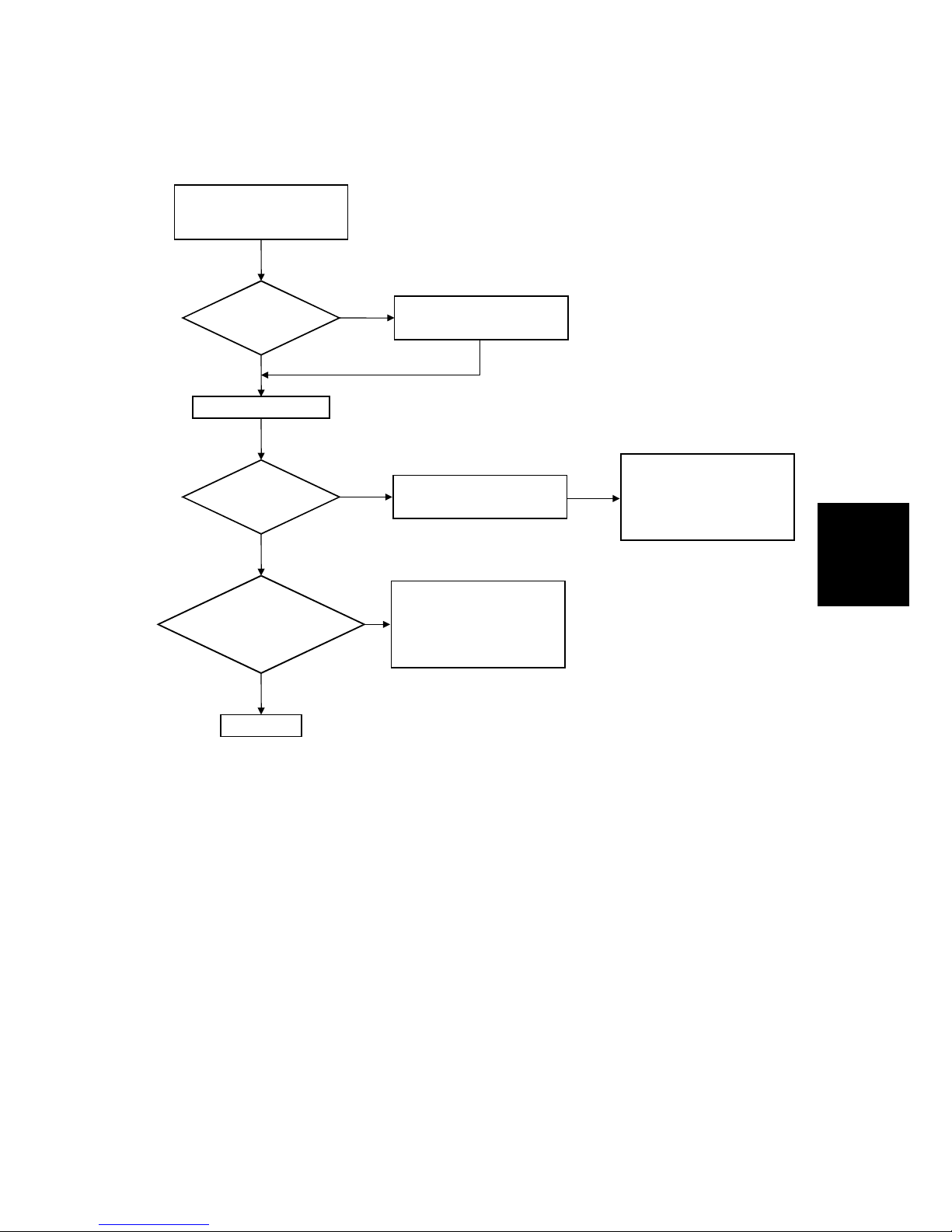
TROUBLESHOOTING
SM 4-27 B174
Trouble-
shooting
Fuser Error
A
C is being
supplied?
Thermostat is open
→
Replace the fusing unit
No
Yes
Yes
Less than 10W?
No
No
Re-install the top
cover and close it
Thermistor, connection
point or Main board defect
→
Replace the component/
board
Measure the resistance
at the both ends of the AC
Line with covers open
Remove the covers
END
The voltage at pin #6 of U5
on the Main PBA is about
3.2V?
If not check CN4 on the
power board.
The voltage at
pin #60 of U36 (CPU) on the
Main PBA is about 2.65 V
when printing?
Yes
Yes
B174T915.WMF
Page 94
TROUBLESHOOTING
B174 4-28 SM
Paper Jam (Mis-Feeding)
Switch them
Does the
solenoid go on at
start of print?
Yes
No
Does the
paper move?
Feeder
sensors assembled
in reverse?
Does the
paper move more
than 100mm?
Yes
Yes
Too many
sheets in the
feeder?
Take out the paper
and re-insert
Main PBA board defective
→ Replace
Solenoid defective
→ Replace
The pick-up unit is
assembled wrong
→ Re-assemble or replace
the unit
Reduce the amount
and re-test
No
No
No
Yes
The sensor and main
PBA defective
→ Replace
Paper end curled?
Is the extender
pulled out?
Pull out the
extender
<Recommendation>
Use the bypass tray (MP Feeder)
for the thick paper such as
envelopes and cardstock
Use recommended
paper
Paper guides
fit the paper width?
No
Yes
No No
Yes
Yes
Yes
B174T916.WMF
Page 95

TROUBLESHOOTING
SM 4-29 B174
Trouble-
shooting
Paper Jam (Jam 1)
Remove the fuser, remove
the paper and replace the
fusing unit, if necessary
Adjust the paper guides to
fit the paper width
The force of the springs
pressing the toner cartridge
is too weak
→ Check the set condition
of the toner cartridge.
Paper
stopped before
the fuser?
Use recommended
paper
The
actuator of the paper
exit sensor works
OK?
Yes
No
Is the paper rolled
around the presseure
roller?
Severe skew
when feeding?
Check the LSU for a
defect
→ Replace it
Check if the actuator exists
and its operation, and
around the main PBA
→ Replace
Check that the rollers
and ribs of the fuser are
in place, and remove
burrs, if any
→ Remove the causes
of jams
Yes
No
Yes
Yes
Paper
stopped before
the OPC?
Feeds
multiple pages?
Remove any
defective parts
The paper
came out
between fuser and
toner cartridge?
Check the input path
to the fuser (such as
mis-assembly)
Check if the transfer
guide is grounded.
Check if the shutter
prevents feeding.
Yes
Yes
Yes
No No
No No
No
Yes
Paper is too thin
or sensitive to
static electricity?
B174T917.WMF
Page 96
TROUBLESHOOTING
B174 4-30 SM
Engine Error
Replace the LSU
Check
Harness-CN7
(Main PBA to
LSU)
Yes
No
Yes
Yes
No
No
No
Yes
Try again to connect or
replace the connector
Replace the Main PBA
Replace the LSU
Replace the Main PBA
END
Check
Main PBA CN7-9,
P_MOTOR Signal
( )
Check
Main PBA CN7-8,
LREADY Signal
( )
Check
Main PBA CN7-4,
LDON Signal
( )
Check
Main PBA CN7-1,
HSYNC Signal
( )
No
Yes
B174T918.WMF
Page 97

TROUBLESHOOTING
SM 4-31 B174
Trouble-
shooting
4.3.5 TONER CARTRIDGE AND DRUM CARTRIDGE SERVICE
Precautions on Safe-keeping of the Drum Cartridge
Excessive exposure to direct light for more than a few minutes may cause damage
to the cartridge.
Service for the Life of Toner Cartridge
If the printed image is light due to the life of the toner cartridge, you can temporarily
improve the print quality by redistributing the toner (shake the toner cartridge). But,
you should replace the toner cartridge to solve the problem completely.
Page 98

TROUBLESHOOTING
B174 4-32 SM
Symptoms of a defective toner cartridge
Fault Signs Cause & Check Solution
1. If the printed image is
light or dirty and untidy–
Shake the toner cartridge
and then recheck.
1) NG: Check the weight of
the toner cartridge
2) OK: Lack of toner, so the
life is nearly ended.
1. For symptoms 1, 2,
and 3
If it becomes better
after shaking, replace
with a new toner
cartridge after 50-100
sheets if the life of
the cartridge is
almost ended.
2. Some part of image is not
printed - Shake the toner
cartridge and then
recheck.
1) NG: Check the weight of
the toner cartridge and
clean the LSU window
with a cotton swab, then
recheck.
2) OK: Lack of toner, so the
life is nearly ended.
2. If it becomes better
after cleaning the
LSU window, then
the toner cartridge is
normal.
(Because of a foreign
substance on the
LSU window, part of
the image was not
printed.)
3. Periodically a "tick tick"
noise occurs - Measure
the cycle and the weight
of the toner cartridge.
3. If the cycle of the
noise is about 2
seconds, the toner
inside the toner
cartridge has almost
ended. (Install a new
toner cartridge after
making about 200
more sheets)
Light image
and partially
blank image
Digital Printer
Digital Printer
Digital Printer
Digital Printer
Digital Printer
B174T923.WMF
• The printed
image is light
or dirty and
untidy.
• Some part of
the image is
not printed.
• Periodically a
"tick tick"
noise occurs.
4. White vertical stripes on
the whole image or part
of the image : Check the
weight of the toner
cartridge.
4. This is caused by
lack of toner, so
replace with a new
toner cartridge.
1. Toner falls on the paper
periodically.
1) Check the cycle of
occurrence.
Check the appearance of
both ends of the OPC drum.
1. If both ends of the
OPC drum are
contaminated with
toner: Replace the
toner cartridge if it is
near the end of its
life.
Toner
contamination
• Toner falls on
the paper
periodically.
• Contaminated
with toner on
prints partly or
over the
whole surface.
2. The center of the printed
matter is contaminated
with toner.
1) Check whether foreign
substances or toner are
stuck to the terminal
(contact point) of the
toner cartridge.
2) Check whether the state
of the terminal assembly
is normal.
2. Is the customer using
recycled toner?
Page 99

TROUBLESHOOTING
SM 4-33 B174
Trouble-
shooting
Fault Signs Cause & Check Solution
1. If light or dark periodical
black dots occur, this is
because the rollers are
contaminated with a
foreign substance or
paper particles.
1) 37.7 mm interval :
Charge roller
2) 94.3 mm interval :
OPC drum
1. Run OPC Cleaning Mode
Print (User Tools – 12.
Maintenance – Clean
Drum) 4-5 times
repeatedly to remove.
Especially check for
foreign substances on
the OPC surface, then
remove them with a
clean gauze moistened
with Isopropyl Alcohol if
necessary.
Caution: Never use normal
(ethyl) alcohol.
White Black
spot
Digital Printer
Digital Printer
Digital Printer
Digital Printer
Digital Printer
B174T927.WMF
• Light or
dark black
dots on the
image
occur
periodically.
• White spots
occur in the
image
periodically.
2. If white spots occur in a
black image at intervals
of 94.3 mm, or black
spots occur elsewhere,
the OPC drum is
damaged or a foreign
substance is stuck to
the surface.
2. If they do not disappear
after you run
OPC
Cleaning Mode Print
(User Tools – 12.
Maintenance – Clean
Drum) 4-5 times.
: at intervals of 94.3mm Replace the OPC Drum.
: at intervals of 37.7mm Remove the foreign
substance, Clean the
Charge Roller
: Broken image - Replace
the toner cartridge.
1. Poor appearance of
the toner cartridge.
1) Check if there is the
damage to the label
and if different
materials are used.
2) Check the appearance
of parts of the toner
cartridge, such as
frame, hopper
.
1.
1) Look for evidence of
disassembling the
toner cartridge.
2) Check if materials other
than normal parts of
the toner cartridge are
added or substituted.
Recycled
product
• Poor
appearance
of the toner
cartridge.
• Dirty and
rough
printouts.
• Bad
background
in the
image.
2. Dirty and rough
printouts.
1) Check whether foreign
substances or toner
are stuck to the
terminal (contact
point) of the toner
cartridge.
2) Check whether the
state of the terminal
assembly is normal.
2. If the toner cartridge
appears to be
disassembled (see 1
above)
1) It occurs when the
toner cartridge is
recycled more than 2
times.
2) If toner that is nearly
expired is collected to
use, it is considered to
be recycled.
Page 100

TROUBLESHOOTING
B174 4-34 SM
Fault Signs Cause & Check Solution
1. The printed image is too
light or dark, or partially
contaminated with
black.
1) Check whether foreign
sub stance or toner are
stuck to the terminal
(point of contact) of the
toner cartridge.
2) Check whether the
terminal assembly is
normal.
1. All of 1, 2 above
1) Remove toner and
foreign substances
adhered to the
contact point of the
toner cartridge.
2) The contact point of
the unit facing the
contact point of the
toner cartridge must
also be cleaned.
3) If the terminal
assembly is unsafe:
• Fully attach the
terminal or
reassemble it after
disassembling.
• Disassemble the
side plate and
push the terminal
to be attached,
then reassemble it.
Ghost &
Image
Contamination
• The printed
image is too
light or dark,
or partially
contaminated
with black.
• Totally
contaminated
with black.
(Black image
printed out)
2. Totally contaminated with
black. (Black image printed
out)
1) Check whether foreign
substances are stuck to
the terminal (point of
contact) of the toner
cartridge and the state of
assembly.
(Especially check the
charge roller terminal.)
2. The OPC drum is not
electrically charged.
Clean the terminals of the
charge roller, then
recheck it.
 Loading...