

Page 1

Model A-C3e/f
(Machine Code: B135/B138)
SERVICE MANUAL
Page 2

IIMPORTANT SAFETY NOTICES
PREVENTION OF PHYSICAL INJURY
1. Before disassembling or assembling parts of the copier and peripherals,
make sure that the copier power cord is unplugged.
2. The wall outlet should be near the copier and easily accessible.
3. Note that some components of the copier and the paper tray unit are
supplied with electrical voltage even if the main power switch is turned off.
4. If any adjustment or operation check has to be made with exterior covers off
or open while the main switch is turned on, keep hands away from electrified
or mechanically driven components.
5. If the Start key is pressed before the copier completes the warm-up period
(the Start key starts blinking red and green alternatively), keep hands away
from the mechanical and the electrical components as the copier starts
making copies as soon as the warm-up period is completed.
6. The inside and the metal parts of the fusing unit become extremely hot while
the copier is operating. Be careful to avoid touching those components with
your bare hands.
HEALTH SAFETY CONDITIONS
1. Never operate the copier without the ozone filters installed.
2. Always replace the ozone filters with the specified ones at the specified
intervals.
3. Toner and developer are non-toxic, but if you get either of them in your eyes
by accident, it may cause temporary eye discomfort. Try to remove with eye
drops or flush with water as first aid. If unsuccessful, get medical attention.
OBSERVANCE OF ELECTRICAL SAFETY STANDARDS
1. The copier and its peripherals must be installed and maintained by a
customer service representative who has completed the training course on
those models.
2. The NVRAM on the system control board has a lithium battery which can
explode if replaced incorrectly. Replace the NVRAM only with an identical
one. The manufacturer recommends replacing the entire NVRAM. Do not
recharge or burn this battery. Used NVRAM must be handled in accordance
with local regulations.
manuals4u.commanuals4u.com
Page 3

1. SAFETY AND ECOLOGICAL NOTES FOR DISPOSAL
Do not incinerate toner bottles or used toner. Toner dust may ignite
suddenly when exposed to an open flame.
2. Dispose of used toner, developer, and organic photoconductors in
accordance with local regulations. (These are non-toxic supplies.)
3. Dispose of replaced parts in accordance with local regulations.
4. When keeping used lithium batteries in order to dispose of them later, do not
put more than 100 batteries per sealed box. Storing larger numbers or not
sealing them apart may lead to chemical reactions and heat build-up.
LASER SAFETY
The Center for Devices and Radiological Health (CDRH) prohibits the repair of
laser-based optical units in the field. The optical housing unit can only be repaired
in a factory or at a location with the requisite equipment. The laser subsystem is
replaceable in the field by a qualified Customer Engineer. The laser chassis is not
repairable in the field. Customer engineers are therefore directed to return all
chassis and laser subsystems to the factory or service depot when replacement of
the optical subsystem is required.
!WARNING
Use of controls, or adjustment, or performance of procedures other than
those specified in this manual may result in hazardous radiation exposure.
!WARNING
WARNING: Turn off the main switch before attempting any of the
procedures in the Laser Unit section. Laser beams can seriously damage
your eyes.
CAUTION MARKING:
Page 4

Conventions in this Manual
This manual uses several symbols.
Symbol What it means
☛
!
"
#
$
%
Refer to section number
See Core Tech Manual for details
Screw
Connector
E-ring
Clip ring
Long Edge Feed (LEF)Short Edge Feed (SEF)
manuals4u.commanuals4u.com
Page 5

TABLE OF CONTENTS
1. INSTALLATION PROCEDURE ................................................... 1-1
1.1 INSTALLATION REQUIREMENTS........................................................... 1-1
1.1.1 ENVIRONMENT .............................................................................. 1-2
1.1.2 MACHINE LEVEL ............................................................................ 1-2
1.1.3 MINIMUM SPACE REQUIREMENTS.............................................. 1-3
1.1.4 POWER REQUIREMENTS.............................................................. 1-5
1.2 INSTALLATION FLOW CHART................................................................ 1-6
1.3 MAIN MACHINE INSTALLATION............................................................. 1-7
1.3.1 ACCESSORY CHECK..................................................................... 1-7
1.3.2 INSTALLATION PROCEDURE........................................................ 1-8
Development Unit and PCU ................................................................. 1-9
Toner Bottle........................................................................................ 1-12
Paper Trays........................................................................................ 1-13
Initialize TD Sensor and Developer.................................................... 1-15
Set Paper Size for Paper Trays.......................................................... 1-16
Electrical Total Counter...................................................................... 1-17
HDD Caution Decal............................................................................ 1-17
Exposure Glass Cleaner .................................................................... 1-17
1.4 PAPER TRAY UNIT INSTALLATION (B542).......................................... 1-18
1.4.1 ACCESSORY CHECK................................................................... 1-18
1.4.2 PAPER TRAY UNIT INSTALLATION PROCEDURE..................... 1-19
1.5 1-BIN TRAY UNIT INSTALLATION (B544)............................................. 1-23
1.5.1 ACCESSORY CHECK................................................................... 1-23
1.5.2 1-BIN TRAY INSTALLATION PROCEDURE................................. 1-24
1.6 BRIDGE UNIT INSTALLATION (B538)................................................... 1-30
1.6.1 ACCESSORY CHECK................................................................... 1-30
1.6.2 BRIDGE UNIT INSTALLATION PROCEDURE.............................. 1-31
1.7 TWO-TRAY FINISHER INSTALLATION (B545)..................................... 1-33
1.7.1 ACCESSORY CHECK................................................................... 1-33
1.7.2 TWO-TRAY FINISHER INSTALLATION PROCEDURE................ 1-34
1.8 PUNCH UNIT INSTALLATION ............................................................... 1-37
1.8.1 ACCESSORY CHECK................................................................... 1-37
1.8.2 PUNCH UNIT INSTALLATION PROCEDURE............................... 1-38
1.9 ARDF INSTALLATION (B541)................................................................ 1-41
1.9.1 ACCESSORY CHECK................................................................... 1-41
1.9.2 ARDF INSTALLATION PROCEDURE........................................... 1-41
1.9.3 ARDF SKEW ADJUSTMENT......................................................... 1-44
1.10 LCT INSTALLATION (B543)................................................................. 1-45
1.10.1 ACCESSORY CHECK................................................................. 1-45
1.10.2 LCT INSTALLATION PROCEDURE............................................ 1-46
1.11 PLATEN COVER INSTALLATION (G329)............................................ 1-48
1.12 BOOKLET FINISHER INSTALLATION (B546) ..................................... 1-49
1.12.1 ACCESSORY CHECK................................................................. 1-49
1.12.2 BOOKLET FINISHER INSTALLATION PROCEDURE ................ 1-50
i
Page 6

1.13 1000 SHEET FINISHER (B408) ........................................................... 1-55
1.13.1 ACCESSORY CHECK................................................................. 1-55
1.13.2 1000 SHEET FINISHER INSTALLATION PROCEDURE ............ 1-56
1.14 FILE FORMAT CONVERTER B519-17 ................................................ 1-59
1.14.1 ACCESSORY CHECK................................................................. 1-59
1.14.2 INSTALLATION PROCEDURE.................................................... 1-59
1.14.3 CHECK ALL CONNECTIONS...................................................... 1-60
2. PREVENTIVE MAINTENANCE SCHEDULE............................... 2-1
2.1 PM TABLE................................................................................................ 2-1
3. REPLACEMENT AND ADJUSTMENT........................................ 3-1
3.1 SPECIAL TOOLS AND LUBRICANTS ............................................... 3-2
3.1.1 SPECIAL TOOLS............................................................................. 3-2
3.1.2 LUBRICANTS .................................................................................. 3-2
3.2 LASER UNIT............................................................................................. 3-3
3.2.1 CAUTION DECAL LOCATIONS ...................................................... 3-3
3.2.2 LASER UNIT.................................................................................... 3-4
3.3 PHOTOCONDUCTOR UNIT (PCU).......................................................... 3-6
3.3.1 PCU ................................................................................................. 3-6
3.3.2 DRUM .............................................................................................. 3-7
3.3.3 PICK-OFF PAWLS........................................................................... 3-9
Pick-off pawl position adjustment......................................................... 3-9
3.3.4 CHARGE ROLLER AND CLEANING ROLLER ............................. 3-10
3.3.5 DRUM CLEANING BLADE 2 ......................................................... 3-11
3.3.6 DRUM CLEANING BLADE 1 ......................................................... 3-12
3.4 FUSING UNIT......................................................................................... 3-13
3.4.1 FUSING UNIT REMOVAL.............................................................. 3-13
3.4.2 FUSING UNIT SIDE FAN............................................................... 3-14
3.4.3 FUSING UNIT CORNER FAN ....................................................... 3-16
3.5 PAPER FEED......................................................................................... 3-17
3.5.1 IDLE ROLLER DUST BLADE ........................................................ 3-17
3.5.2 REGISTRATION ROLLER DUST BLADE ..................................... 3-18
3.6 PRINTED CIRCUIT BOARDS ................................................................ 3-19
3.6.1 IOB................................................................................................. 3-19
IOB DIP Switch Settings (SW101) ..................................................... 3-20
3.7 HARD DISK, CONTROLLER BOARD .................................................... 3-21
4. TROUBLESHOOTING................................................................. 4-1
4.1 SERVICE CALL CONDITIONS................................................................. 4-1
4.1.1 SUMMARY....................................................................................... 4-1
4.1.2 SC CODE DESCRIPTIONS............................................................. 4-2
4.2 ELECTRICAL COMPONENT DEFECTS................................................ 4-10
4.2.1 SENSORS ..................................................................................... 4-10
4.2.2 SWITCHES.................................................................................... 4-11
4.3 BLOWN FUSE CONDITIONS................................................................. 4-11
4.4 LEDS ...................................................................................................... 4-12
4.5 TEST POINTS ........................................................................................ 4-12
ii
manuals4u.commanuals4u.com
Page 7

5. SERVICE TABLES...................................................................... 5-1
5.1 SERVICE PROGRAM MODE TABLES .................................................... 5-1
5.1.1 SERVICE TABLE KEY..................................................................... 5-1
5.1.2 SERVICE TABLES .......................................................................... 5-2
SP1-xxx: Feed...................................................................................... 5-2
SP2-xxx: Drum..................................................................................... 5-6
SP3-xxx: Process............................................................................... 5-16
SP4-xxx: Scanner .............................................................................. 5-17
SP5-xxx: Mode................................................................................... 5-26
SP6-xxx: Peripherals.......................................................................... 5-46
SP7-xxx: Data Log ............................................................................. 5-48
SP8-xxx: Data Log2 ........................................................................... 5-56
5.1.3 TEST PATTERN PRINTING: SP2-902 .......................................... 5-90
Test Pattern Table (SP2-902-2: IPU Test Print)................................. 5-90
Test Pattern Table: SP2-902-3 Printing Test Patterns ....................... 5-91
5.1.4 INPUT CHECK............................................................................... 5-92
Main Machine Input Check: SP5-803................................................. 5-92
ARDF Input Check: SP6-007 ............................................................. 5-96
5.1.5 OUTPUT CHECK........................................................................... 5-97
Main Machine Output Check: SP5-804 .............................................. 5-97
ARDF Output Check: SP6-008) ......................................................... 5-99
5.1.6 SMC PRINT OUT LISTS: SP5-990................................................ 5-99
5.1.7 MEMORY CLEAR: SP5-801........................................................ 5-100
5.2 DIP SWITCHES.................................................................................... 5-102
5.3 USING THE DEBUG LOG.................................................................... 5-103
5.3.1 SWITCHING ON AND SETTING UP SAVE DEBUG LOG .......... 5-103
5.3.2 RETRIEVING THE DEBUG LOG FROM THE HDD ................... 5-107
5.3.3 RECORDING ERRORS MANUALLY .......................................... 5-107
6. DETAILED SECTIOIN DESCRIPTIONS...................................... 6-1
6.1 BOARD STRUCTURE.............................................................................. 6-2
6.1.1 BLOCK DIAGRAM........................................................................... 6-2
6.1.2 CONTROLLER ................................................................................ 6-4
6.2 IMAGE PROCESSING ............................................................................. 6-7
6.2.1 OVERVIEW...................................................................................... 6-7
6.2.2 SBU (SENSOR BOARD UNIT)........................................................ 6-8
6.2.3 AUTO IMAGE DENSITY (ADS) ....................................................... 6-9
6.2.4 IPU (IMAGE PROCESSING UNIT)................................................ 6-10
Overview ............................................................................................ 6-10
6.2.5 IMAGE PROCESSING MODES .................................................... 6-11
6.2.6 SUMMARY OF IMAGE PROCESSING FUNCTIONS ................... 6-13
6.2.7 IMAGE PROCESSING STEPS AND RELATED SP MODES........ 6-14
Text Mode .......................................................................................... 6-14
Text/Photo Mode................................................................................ 6-15
Photo Mode........................................................................................ 6-16
Pale (Low-Density Mode)................................................................... 6-17
Generation Copy Mode ...................................................................... 6-18
iii
Page 8

v
6.2.8 PRE-FILTERING............................................................................ 6-19
6.2.9 BACKGROUND ERASE ................................................................ 6-20
6.2.10 INDEPENDENT DOT ERASE...................................................... 6-21
6.2.11 LINE WIDTH CORRECTION ....................................................... 6-22
6.2.12 FILTERING .................................................................................. 6-23
Interactive SP Codes ......................................................................... 6-23
Text Mode MTF Filter......................................................................... 6-27
Text/Photo, Photo Mode Filter............................................................ 6-28
Pale, Generation Mode Filter ............................................................. 6-29
Photo Mode Smoothing for Dithering ................................................. 6-30
Photo Mode Grayscale....................................................................... 6-30
Photo Mode Image Quality................................................................. 6-31
6.2.13 OTHERS...................................................................................... 6-32
Vertical Black Line Correction ............................................................ 6-32
Density Settings ................................................................................. 6-32
ADS Level .......................................................................................... 6-33
6.2.14 PRACTICAL APPLICATION OF SP MODES .............................. 6-34
Solving Problems ............................................................................... 6-34
Recommended Settings for MTF Filters............................................. 6-35
6.3 PHOTOCONDUCTOR UNIT (PCU)........................................................ 6-37
6.3.1 OVERVIEW.................................................................................... 6-37
6.3.2 DRUM CLEANING......................................................................... 6-38
6.4 DRUM CHARGE..................................................................................... 6-39
6.4.1 CORRECTION FOR PAPER WIDTH AND THICKNESS............... 6-39
6.4.2 DEVELOPMENT BIAS................................................................... 6-40
Mechanism......................................................................................... 6-40
Correction for paper width and thickness (by-pass tray only)............. 6-40
6.5 PAPER FEED......................................................................................... 6-41
6.5.1 PAPER REGISTRATION............................................................... 6-41
6.6 IMAGE FUSING AND PAPER EXIT....................................................... 6-42
6.6.1 CLEANING MECHANISM.............................................................. 6-42
6.6.2 HOT ROLLER STRIPPER CLEANING.......................................... 6-43
6.6.3 FUSING TEMPERATURE CONTROL........................................... 6-45
Temperature Control.......................................................................... 6-46
Fusing Idling Temperature ................................................................. 6-47
6.6.4 CPM DOWN FOR THICK PAPER ................................................. 6-48
6.6.5 COOLING AND OVERHEAT PROTECTION................................. 6-49
6.6.6 TONER SCATTER PREVENTION ................................................ 6-50
i
manuals4u.commanuals4u.com
Page 9

v
PERIPHERALS
BOOKLET FINISHER (B546)
1. OVERALL MACHINE INFORMATION ..................................B546-1
1.1 MECHANICAL COMPONENT LAYOUT............................................. B546-1
2. DETAILED DESCRIPTIONS .................................................B546-2
2.1 JUNCTION GATE MECHANISM ........................................................ B546-2
2.1.1 SHIFT TRAY MODE .................................................................. B546-2
A4/LT sideways or shorter ............................................................. B546-2
Longer than A4 sideways............................................................... B546-2
2.1.2 PROOF TRAY MODE................................................................ B546-3
2.1.3 BOOKLET STITCH MODE ........................................................ B546-3
2.2 PRE-STACK MECHANISM ................................................................ B546-4
2.3 PAPER SHIFT MECHANISM ............................................................. B546-5
2.4 PAPER POSITIONING MECHANISM ................................................ B546-6
2.5 STAPLER UNIT MOVEMENT MECHANISM...................................... B546-7
2.5.1 DRIVE........................................................................................ B546-7
2.5.2 MOVEMENT .............................................................................. B546-7
Front and Rear Stapling................................................................. B546-7
Tow-position Stapling..................................................................... B546-7
2.6 STAPLER ........................................................................................... B546-8
2.7 SHIFT TRAY MECHANISM ................................................................ B546-9
2.8 BOOKLET UNIT GATE MECHANISM.............................................. B546-10
2.9 RELAY ROLLER AND POSITIONING PLATE MECHANISM........... B546-12
2.10 POSITIONING ROLLER MECHANISM .......................................... B546-13
2.11 BOOKLET UNIT JOGGER MOVEMENT MECHANISM................. B546-14
2.12 BOOKLET STAPLER UNIT ............................................................ B546-15
2.13 PAPER FOLDER MECHANISM ..................................................... B546-16
3. REPLACEMENT AND ADJUSTMENT................................B546-18
3.1 REMOVAL ........................................................................................ B546-18
3.1.1 UPPER DOOR......................................................................... B546-18
3.1.2 UPPER REAR COVER............................................................ B546-19
3.1.3 LOWER REAR COVER ........................................................... B546-19
3.1.4 TOP COVER............................................................................ B546-20
3.1.5 UPPER INNER COVER........................................................... B546-20
3.1.6 SHIFT TRAY UNIT................................................................... B546-21
3.1.7 UPPER SHIFT GUIDE............................................................. B546-22
3.1.8 LOWER SHIFT GUIDE ............................................................ B546-22
3.1.9 EXIT UNIT................................................................................ B546-23
3.1.10 BUFFER ROLLER UNIT........................................................ B546-24
3.1.11 STAPLER............................................................................... B546-25
3.1.12 FINISHER BOARD ...............................................................B546-26
3.1.13 BOOKLET UNIT..................................................................... B546-27
3.1.14 FOLDER ROLLERS............................................................... B546-29
Page 10

3.1.15 FOLDER PLATE.................................................................... B546-32
Removal....................................................................................... B546-32
Reinstalling................................................................................... B546-33
3.1.16 BOOKLET STAPLER UNIT ................................................... B546-34
Removal....................................................................................... B546-34
Adjustment ................................................................................... B546-35
3.1.17 BOOKLET BOARD ................................................................ B546-37
3.1.18 POSITIONING PLATE UNIT.................................................. B546-37
3.1.19 1ST AND 2ND BOOKLET UNIT GATES ............................... B546-38
3.2 ADJUSTMENT.................................................................................. B546-39
3.2.1 SHIFT TRAY HEIGHT ............................................................. B546-39
3.2.2 JOGGER FENCE POSITION................................................... B546-40
3.2.3 STAPLING POSITION............................................................. B546-41
3.2.4 BOOKLET STAPLING POSITION ........................................... B546-42
SPECIFICATIONS.................................................................... SPEC-1
1. GENERAL SPECIFICATIONS.............................................................SPEC-1
2. MACHINE CONFIGURATION .............................................................SPEC-3
3. OPTIONAL EQUIPMENT ...................................................................SPEC-5
vi
manuals4u.commanuals4u.com
Page 11
1 August, 2003 INSTALLATION REQUIREMENTS
1. INSTALLATION PROCEDURE
!CAUTION
Never turn off the main power switch when the power LED is lit or flashing.
To avoid damaging the hard disk or memory, press the operation power
switch to switch the power off, wait for the power LED to go off, and then
switch the main power switch off.
NOTE: The main power LED lights or flashes while the platen cover or ARDF is
open, while the main machine is communicating with a facsimile or the
network server, or while the machine is accessing the hard disk or memory
for reading or writing data.
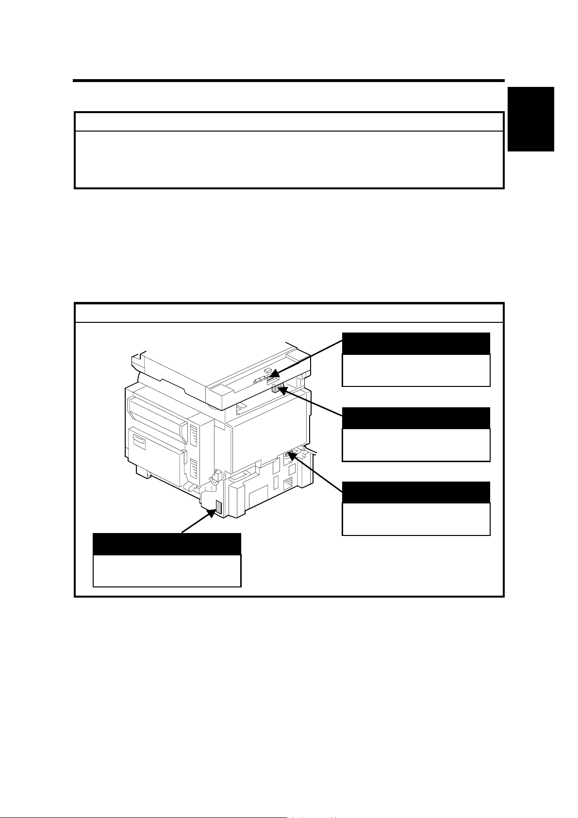
1.1 INSTALLATION REQUIREMENTS
CAUTION
!
ARDF
Installation
B135I016.WMF
LCT
“Rating Voltage of Output
Connector, Max. DC24 V”
“Rating Voltage of Output
Connector, Max. DC24 V”
Scanner Unit
“Rating Voltage of Output
Connector, Max. DC24 V”
Finisher
“Rating Voltage of Output
Connector, Max. DC24 V”
1-1
Page 12

INSTALLATION REQUIREMENTS 1 August, 2003
1.1.1 ENVIRONMENT
1. Temperature Range:
2. Humidity Range:
3. Ambient Illumination:
10 °C to 32 °C (50 °F to 90 °F)
15% to 80% RH
Less than 1,500 lux (do not expose to direct
sunlight.)
4. Ventilation:
5. Ambient Dust:
Room air should turn over
at least 30 m
Less than 0.10 mg/m
3
/hr/person
3
(2.7 x 10/6 oz/yd3)
6. Avoid areas exposed to sudden temperature changes:
1) Areas directly exposed to cool air from an air conditioner.
2) Areas directly exposed to heat from a heater.
7. Do not place the machine where it will be exposed to corrosive gases.
8. Do not install the machine at any location over 2,000 m (6,500 ft.) above sea
level.
9. Place the main machine on a strong and level base. Inclination on any side
should be no more than 5 mm (0.2").
10. Do not place the machine where it may be subjected to strong vibrations.
1.1.2 MACHINE LEVEL
Front to back: Within 5 mm (0.2") of level
Right to left: Within 5 mm (0.2") of level
1-2
manuals4u.commanuals4u.com
Page 13
1 August, 2003 INSTALLATION REQUIREMENTS
A
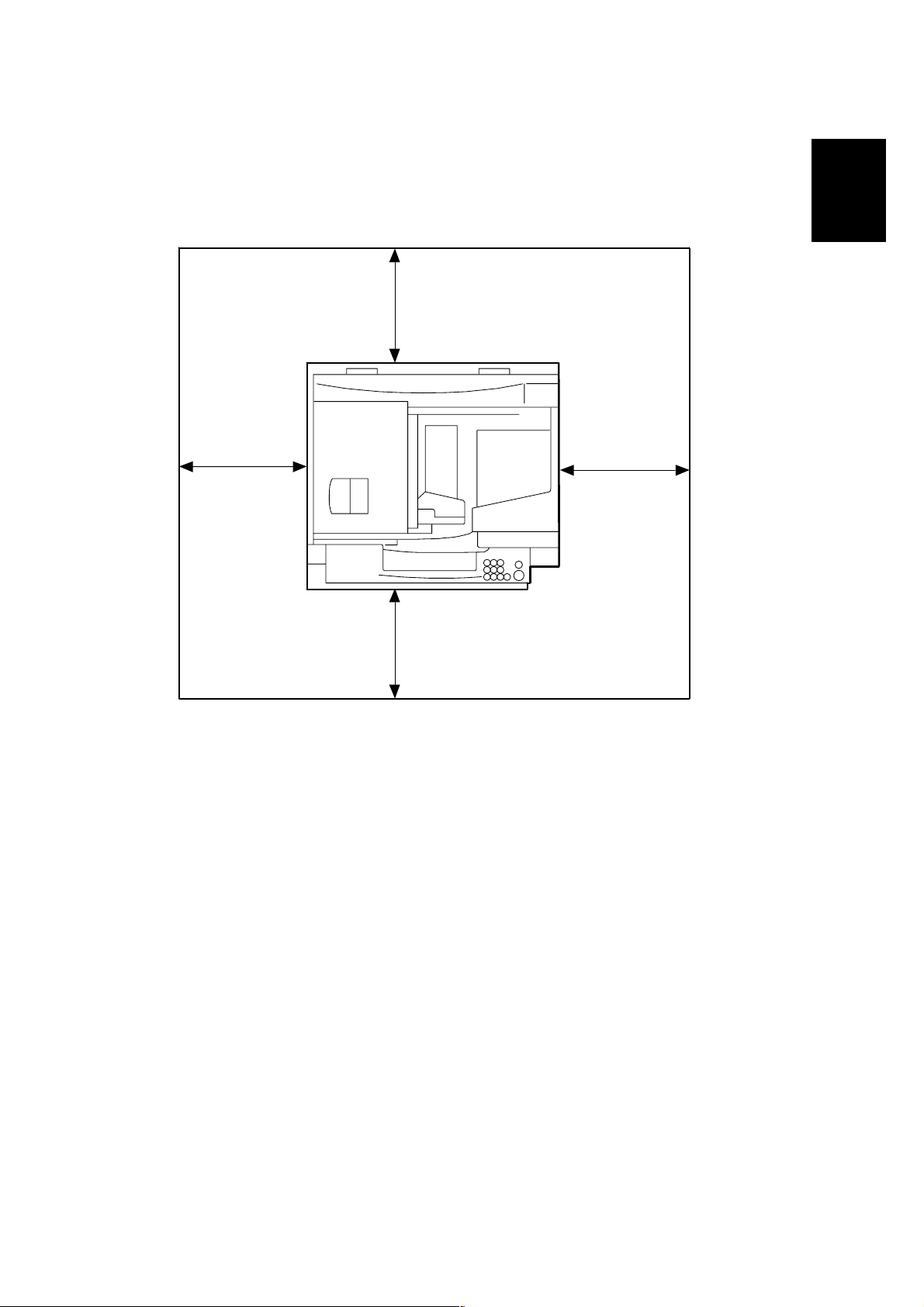
1.1.3 MINIMUM SPACE REQUIREMENTS
Place the main machine near the power source, providing clearance as shown:
Installation
C
B
D
A
B135I010.WMF
: Front: >75 cm (29.6")
B: Left: > 10 cm (4")
C: Rear: > 10 cm (4")
D: Right > 10 cm (4")
NOTE: The 75 cm (29.5") recommended for the space at the front is for pulling out
the paper tray only. If the operator stands at the front of the main machine,
more space is required.
1-3
Page 14
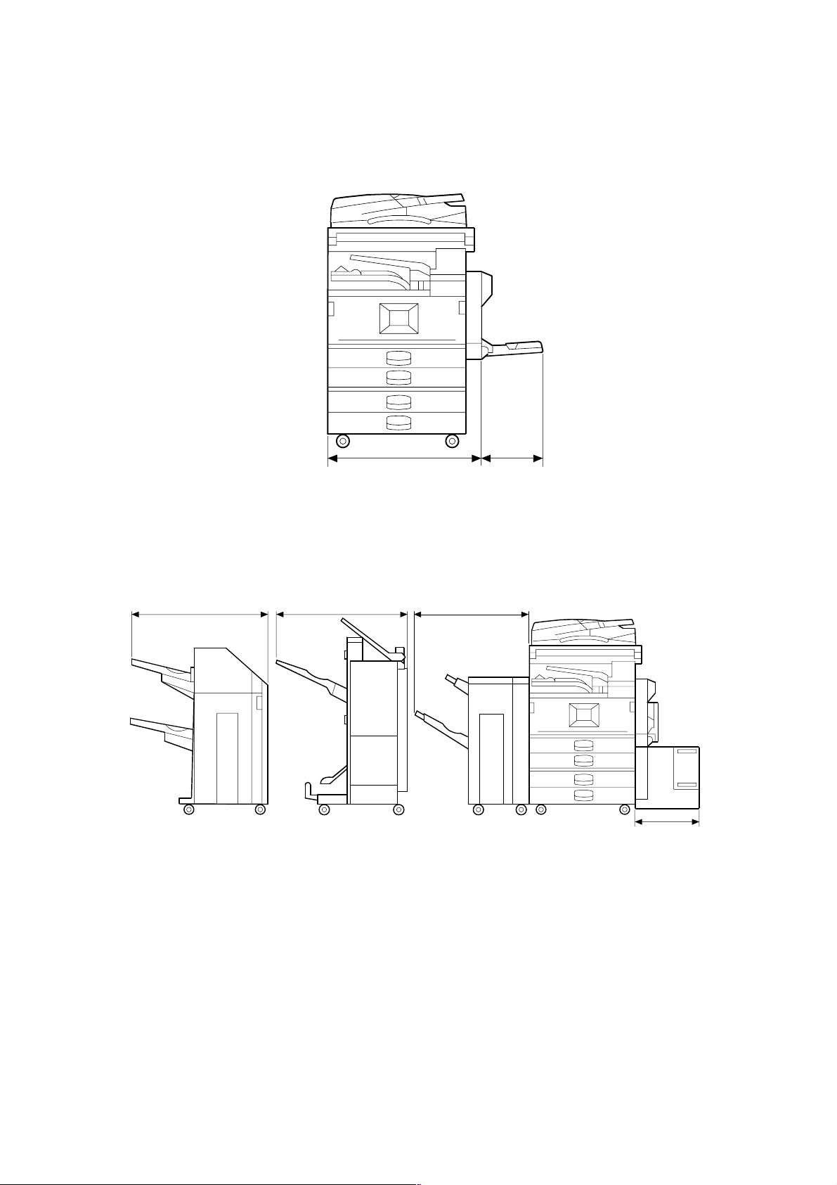
INSTALLATION REQUIREMENTS 1 August, 2003
726 mm (28.6") 670 mm (23.4")
670 mm (26.4")
620 mm (24.4")
180 mm (7.1")
B135I012.WMF
B135I014.WMF
1-4
manuals4u.commanuals4u.com
Page 15

1 August, 2003 INSTALLATION REQUIREMENTS
1.1.4 POWER REQUIREMENTS
!CAUTION
1. Make sure that the wall outlet is near the main machine and easily
accessible. Make sure the plug is firmly inserted in the outlet.
2. Avoid multi-wiring.
3. Be sure to ground the machine.
1. Input voltage level:
North America 120 V, 60 Hz: More than 12.5 A
Europe/Asia 220 V ~ 240V, 50 Hz/60 Hz: more than 6.8 A
2. Permissible voltage fluctuation: ±10 %
3. Never set anything on the power cord.
Installation
1-5
Page 16
INSTALLATION FLOW CHART 1 August, 2003
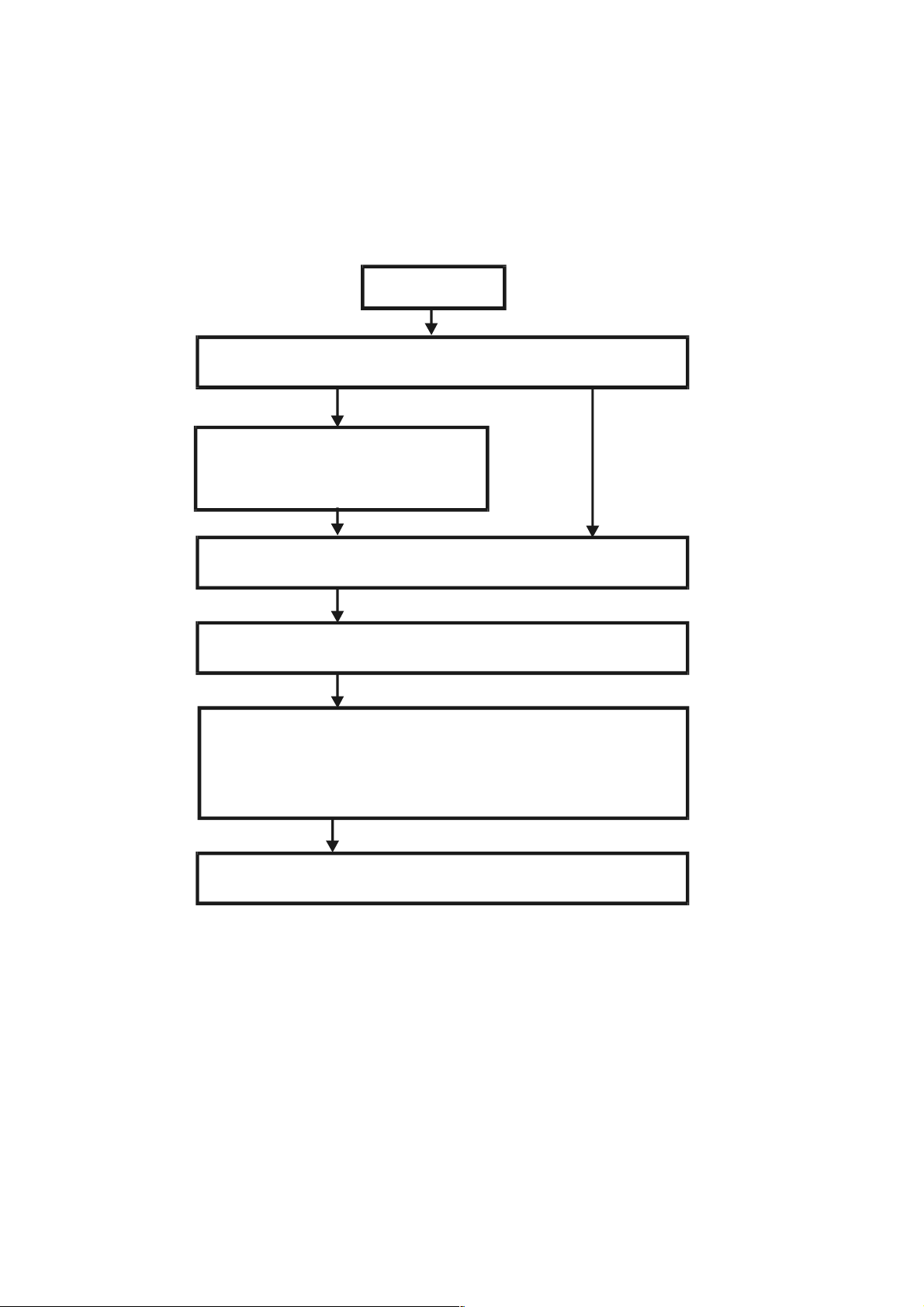
1.2 INSTALLATION FLOW CHART
The following flow chart shows how to install the optional units more efficiently.
Unpack Copier
Does the user require the Paper Tray Unit, LCT, or Finisher?
Yes No
Place Copier on the paper tray unit
Install the paper tray unit
Install the copier
Install the bridge unit (if required)
If the customer requires the 1-bin tray:
Remove the scanner unit
Install the 1-bin tray
Replace the scanner unit
Install the remaining options in any order
Bridge Unit: Needed for the finishers and external output tray.
Paper Tray Unit: Needed for LCT and finishers.
B135I510.WMF
Other requirements: See Overall Machine Information – Installation Option Table.
1-6
manuals4u.commanuals4u.com
Page 17

1 August, 2003 MAIN MACHINE INSTALLATION
1.3 MAIN MACHINE INSTALLATION
1.3.1 ACCESSORY CHECK
Check the quantity and condition of the accessories in the box against the following
list:
Description Q’ty
1. Operation Instructions – System Setting............................... 1
2. Operation Instructions – Copy Reference ............................. 1
3. Exposure Glass Cleaner Holder............................................ 1
4. Exposure Glass Cleaner ....................................................... 1
5. Paper Size Decal .................................................................. 1
6. Middle Front Cover................................................................ 1
7. NECR – English (-17, -19, -21, -28, -29, -57 Machines)........ 1
8. NECR – Multi-Language (-26, -27, -66, -67 Machines)......... 1
9. HDD Caution Decals (-17, -29, -57 Machines)...................... 1
10. Model Name Decal (-17, -29, -57 Machines) ........................ 1
11. Stamp (-17 Machine)............................................................. 1
Installation
12. EU Safety Information (-26, -27, -66, -67 Machines)............. 1
13. Operation Panel Indicator Decals
(-26, -27, -66, -67 Machines)................................................. 1
14. Address Information Sheet – China (-21 Machine) ............... 1
15. Paper Caution Sheet – China (-21 Machine) ........................ 1
16. Energy Start Sticker (-26, -66 Machines) .............................. 1
1-7
Page 18
MAIN MACHINE INSTALLATION 1 August, 2003
1.3.2 INSTALLATION PROCEDURE
[A]
[B]
[D]
[C]
B135I100.WMF
B135I102.WMF
B135I103.WMF
[D]
[E]
B135I101.WMF
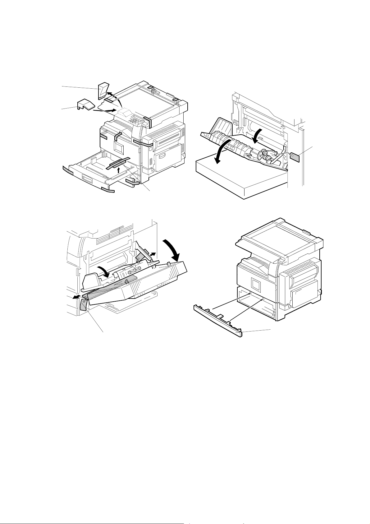
1. Remove the main machine from the box, and remove all shipping retainers and
tapes.
NOTE: Store all shipping retainers as you remove them. You will need them if
the machine is moved to another location in the future.
2. Remove scanner cushion [A], and install the end fence [B].
3. Pull out the paper trays and remove all tape and bottom plate stoppers [C].
4. On the right side of the machine, open the by-pass tray, duplex unit, and
transfer right cover, and then remove all the shipping retainers [D]
NOTE: If the paper tray unit is to be installed, do this now. (☛1.4)
5. If the paper tray unit is not to be installed, install the middle front cover [E]
(provided in the second paper tray).
1-8
manuals4u.commanuals4u.com
Page 19
1 August, 2003 MAIN MACHINE INSTALLATION
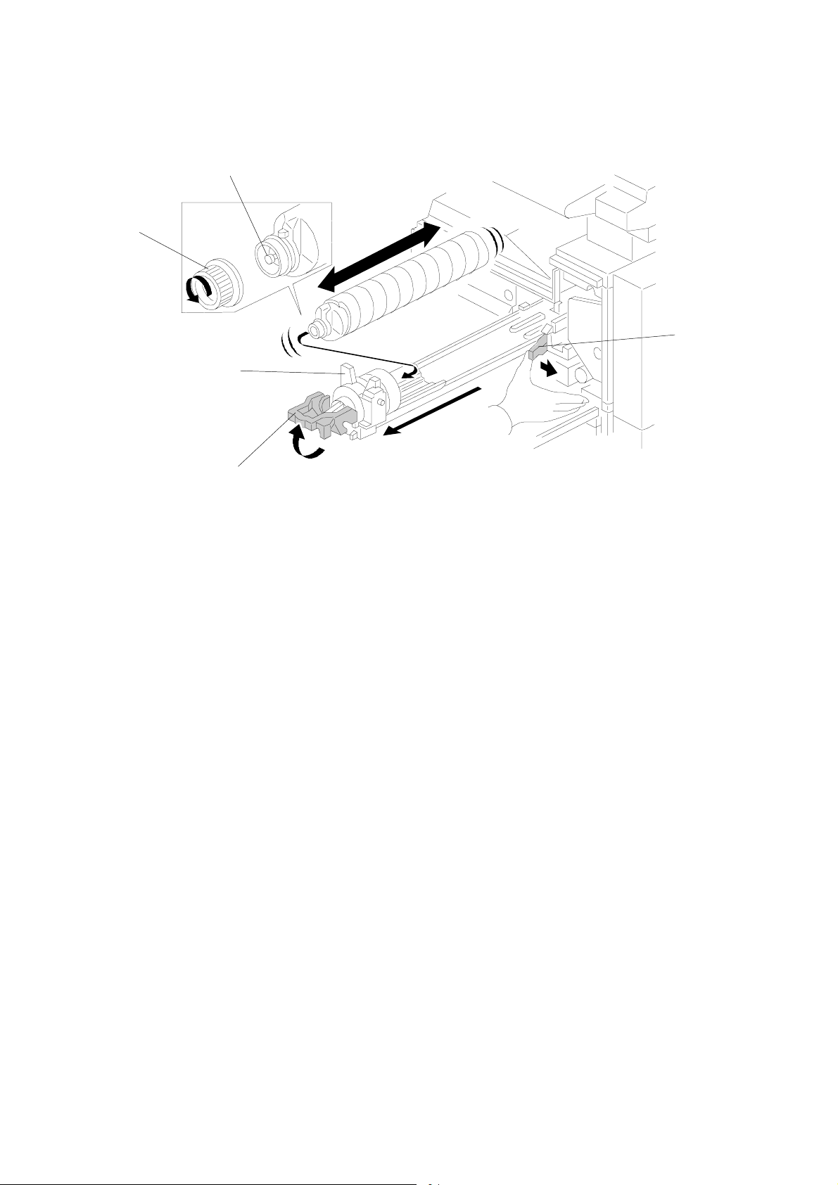
Development Unit and PCU
[C]
[A]
[B]
B135I104.WMF
B135I900.WMF
Installation
[G]
[E]
[F]
B135I511.WMF
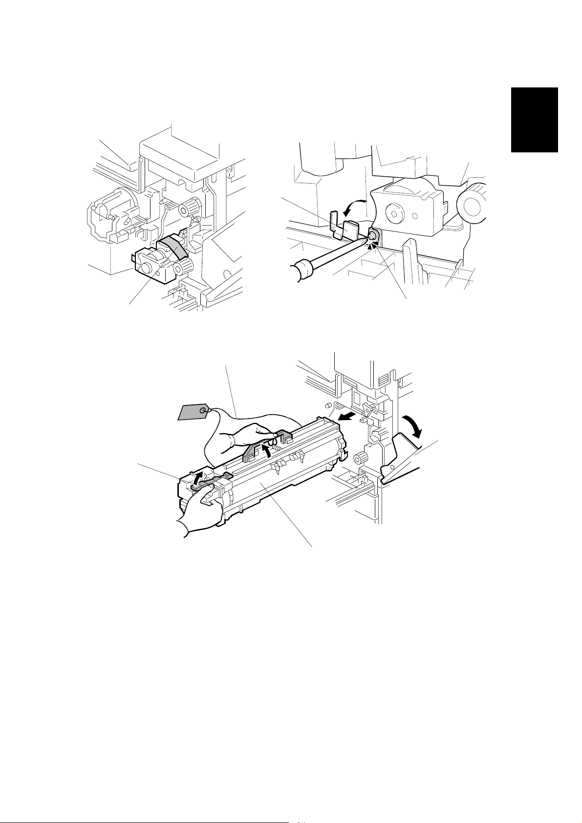
1. Open the front cover and remove the tape and retainers [A].
2. Loosen [B] (! x 1) and rotate the bracket [C].
3. Open the right cover [D].
4. Raise the lever [E]
[D]
5. Holding the PCU [F] as shown slide it out and place it on a clean flat surface.
6. Remove clamps and wire [G].
1-9
Page 20
MAIN MACHINE INSTALLATION 1 August, 2003
[A]
B135I512.WMF
[C]
[B]
B135I105.WMF
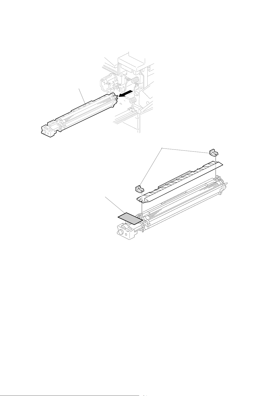
7. Spread a large piece of paper on a flat surface.
NOTE: Make sure the area is free of pins, paper clips, staples, etc. to avoid
attraction to the magnetic development roller.
8. Slide the development unit [A] out and place it on the paper.
9. Remove the tape and tag [B] from the development unit
10. Remove the entrance seal plate [C] (" x 2).
1-10
manuals4u.commanuals4u.com
Page 21
1 August, 2003 MAIN MACHINE INSTALLATION
[A]
[C]
[B]
B135I106.WMF
[D]
B135I513.WMF
Installation
B135I019.WMF
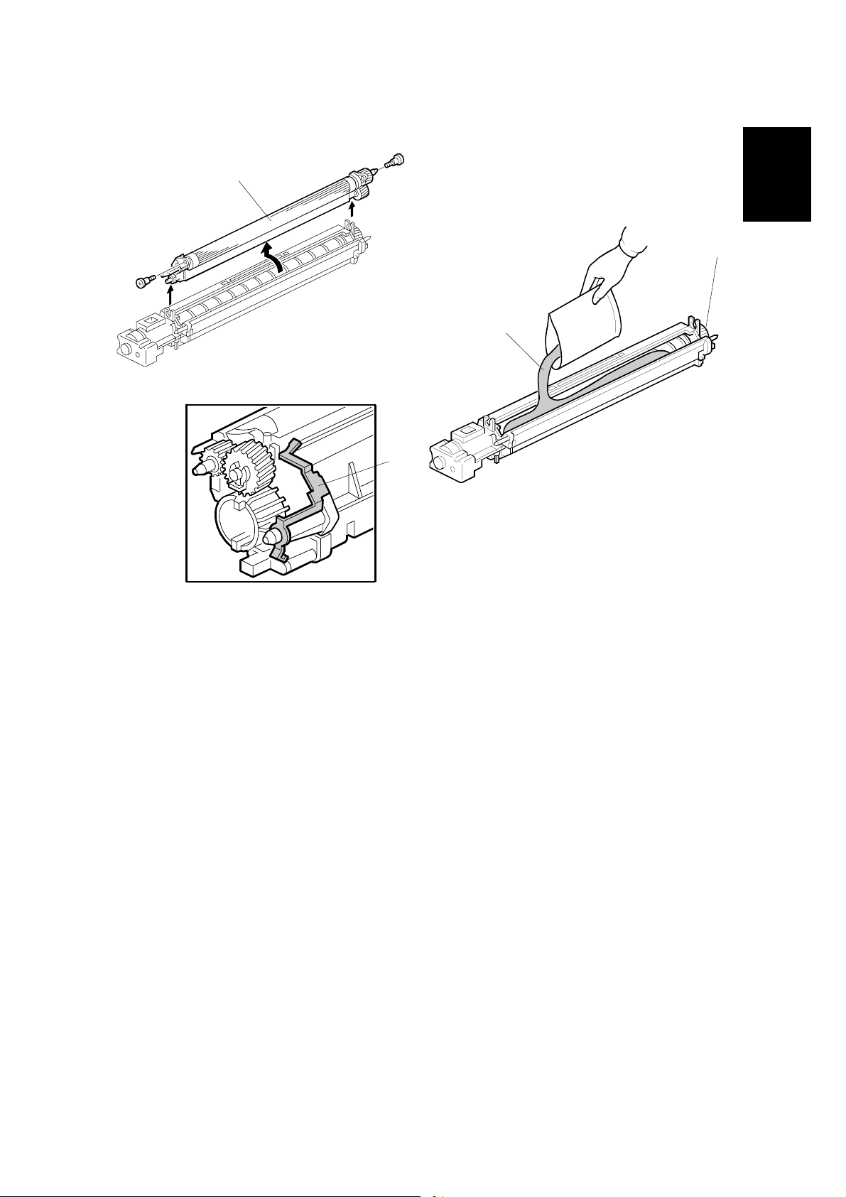
11. Remove the development roller unit [A], and set it on the paper.
12. Pour the developer [B] into the development unit.
NOTE: The developer lot number is embossed on the end of the developer
package. Do not discard the package until you have recorded the lot
number. (☛1-15)
1) Pour approximately 1/3 of the developer evenly along the length of the
development unit.
2) Rotate the drive gear [C] to work the developer into the unit.
3) Repeat until all the developer is in the development unit.
4) Continue to turn the drive gear until the developer is even with the top of the
unit.
13. Reassemble the development unit.
NOTE: Make sure that the earth plate [D] is positioned correctly.
14. Re-install the development unit and PCU.
1-11
Page 22
MAIN MACHINE INSTALLATION 1 August, 2003
[E]
[D]
[B]
[C]
[A]
B135I514.WMF
Toner Bottle
1. Raise the toner bottle holder lever [A], push the lever [B] to the side, and then
pull the toner bottle holder [C] out.
2. Shake the new toner bottle well.
NOTE: Do not remove the toner bottle cap [D] until after shaking.
3. Unscrew the bottle cap and set the bottle in the holder.
NOTE: Do not touch the inner bottle cap [E].
4. Push the toner bottle holder into the main machine until it locks in place, and
then lower the holder lever to secure the toner bottle.
NOTE: The holder lever cannot be lowered unless the toner bottle is installed.
1-12
manuals4u.commanuals4u.com
Page 23
1 August, 2003 MAIN MACHINE INSTALLATION
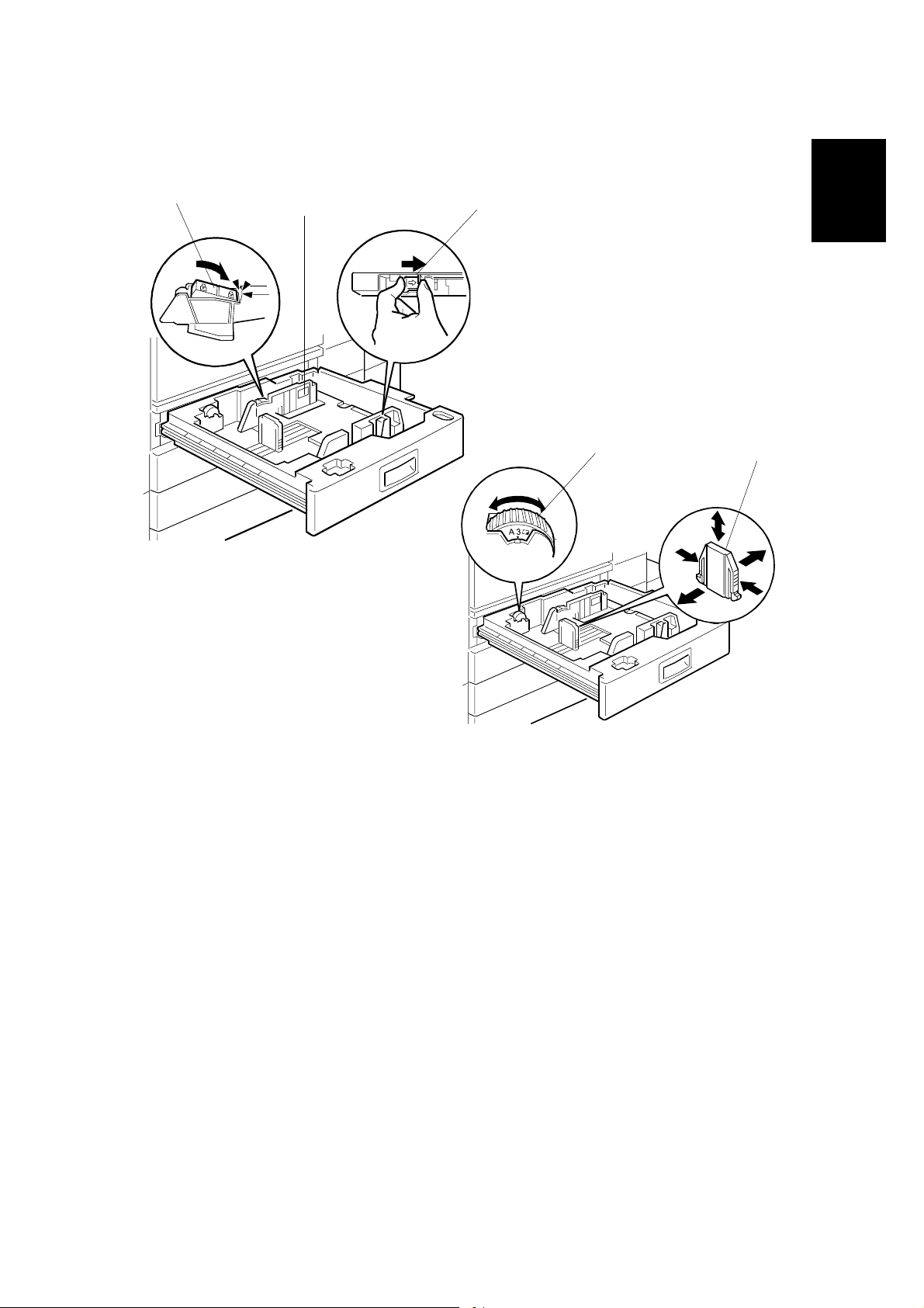
Paper Trays
B135I107.WMF
[A]
[C]
[B]
[D]
Installation
[E]
B135I109.WMF
1. Open the 1st paper tray, and then press down on the right side of the lock [A]
switch to unlock the side fences.
2. Press in on the sides of the fence release [B], and slide the side fences [C] to
the appropriate mark for the paper size.
3. Turn the dial [D] to the correct setting for the paper size.
4. Pinch the sides of the bottom fence [E] and move it to the appropriate mark for
the paper size, then load the paper.
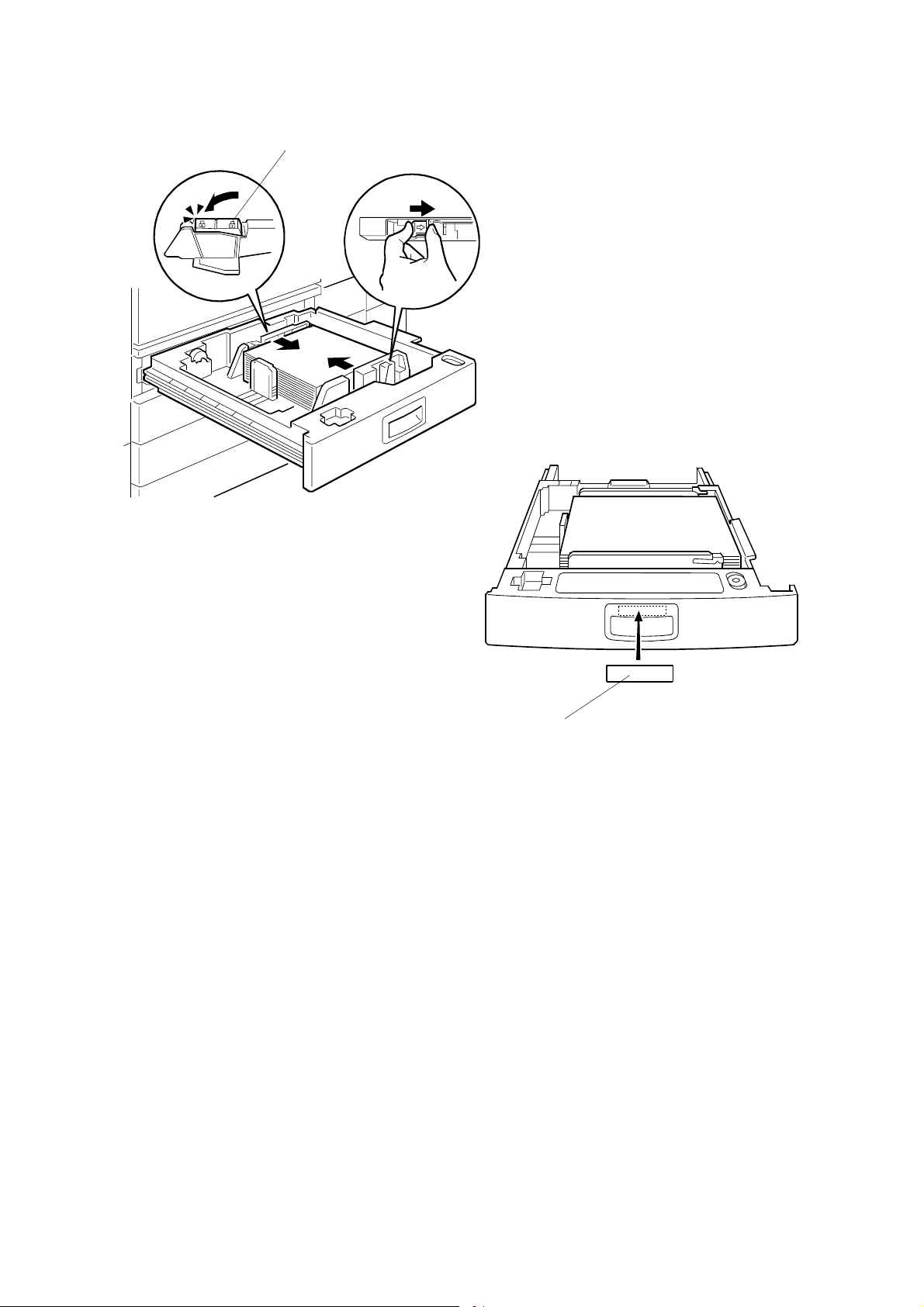
5. Check the position of the stack.
• Confirm that there is no gap between the stack and the side fences. If you
see a gap, adjust the position of the side fences.
• After loading the stack, confirm that the right side of the stack is not on top of
both cushions.
1-13
Page 24
MAIN MACHINE INSTALLATION 1 August, 2003
[A]
B135I108.WMF
B135I110.WMF
[B]
6. Press down the lock [A] to lock the side fences.
7. Attach the appropriate paper size decal [B] to the paper tray.
8. Paper size decals are also used for the optional paper tray unit. Keep any
remaining decals for use with the paper tray unit.
9. Repeat this procedure to load paper in the 2nd paper tray.
1-14
manuals4u.commanuals4u.com
Page 25
1 August, 2003 MAIN MACHINE INSTALLATION
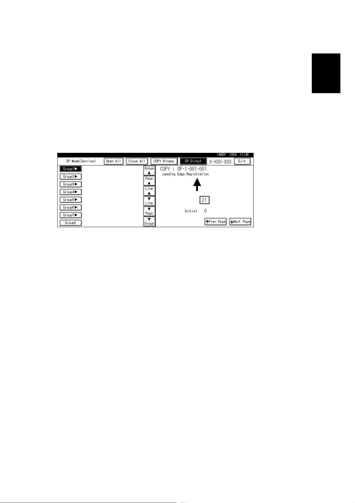
Initialize TD Sensor and Developer
1. Connect the main machine to the power outlet, switch on the main machine,
and wait for the fusing unit to warm up.
2. On the operation panel, press Clear Mode
".
3. Use the number keys to enter 107.
4. Press and hold Clear/Stop # for three seconds.
5. On the touch-panel, press Copy SP.
6. Press SP Direct to highlight “SP Direct”, enter 2801, and then press $.
Installation
B135I500.WMF
7. When the message prompts you to enter the lot number of the developer, enter
the 7-digit lot number, press [Yes], and then press [Execute] on the touchpanel. This initializes the TD sensor.
NOTE: The lot number is printed on the end of the developer package.
Recording the lot number could help troubleshoot problems later. If the
lot number is unavailable, enter any seven-digit number.
8. Press SP Direct to highlight “SP Direct” and enter 2805, press $, and then
press Execute on the touch-panel. This initializes the developer.
9. Press Exit twice to return to the copy window.
1-15
Page 26

MAIN MACHINE INSTALLATION 1 August, 2003
Set Paper Size for Paper Trays
1. Press User Tools/Counter #.
B135I501.WMF
2. On the touch panel, press System Settings.
B135I502.WMF
3. Press the Paper Size Setting tab.
4. Press the button for the tray to change.
5. Change the setting and press the [OK] button.
6. Repeat for each tray installed.
7. Press Exit twice to return to the main display
• The 1st, 2nd, 3rd, and 4th paper trays are provided with paper size dial
selectors. The dial settings on the paper trays have priority over the UP
settings. However, if you select the asterisk (*) position on the paper size
dial, you can select the paper size with the UP setting.
8. Check the copy quality and machine operation.
NOTE: The test pattern print procedure is slightly different for this machine.
Use SP2-902 and select 2 for the IPU Test Print or 3 for the Print Test
Patterns. (☛ Chapter 5, 5.1.3 Test Pattern Printing)
1-16
manuals4u.commanuals4u.com
Page 27
1 August, 2003 MAIN MACHINE INSTALLATION
Electrical Total Counter
The electrical total counter no longer requires initialization. The new incrementing
counter is set to “0” at the factory.
NOTE: SP7825 (Total Counter Reset) remains in the Service but executing this SP
has no effect.
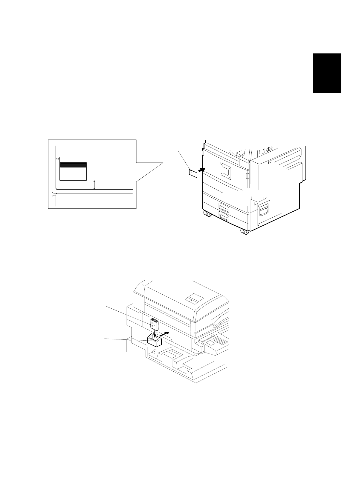
HDD Caution Decal
[A]
10 mm (0.4")
25 mm (1.0")
Installation
B135I017.WMF
1. Attach the HDD Caution decal [A] to the front cover.
Exposure Glass Cleaner
[C]
[B]
B135I111.WMF
B135I018.WMF
1. Attach the exposure glass cleaner holder [B] to the left side of the machine.
2. Place the exposure glass cleaner [C] inside the holder.
NOTE: The exposure glass cleaner is used to clean the ARDF exposure glass,
the glass strip to the left of the large exposure glass.
1-17
Page 28

PAPER TRAY UNIT INSTALLATION (B542) 1 August, 2003
1.4 PAPER TRAY UNIT INSTALLATION (B542)
1.4.1 ACCESSORY CHECK
Check the quantity and condition of the accessories in the box against the following
list:
Description Q’ty
1. Knob Screw – M3.................................................................. 1
2. Knob Screw – M4.................................................................. 1
3. Joint Bracket ......................................................................... 1
4. Front Stand ........................................................................... 1
5. Rear Stand............................................................................ 1
6. Stand Bracket ....................................................................... 1
7. NECR.................................................................................... 1
8. Installation Procedure ........................................................... 1
1-18
manuals4u.commanuals4u.com
Page 29
1 August, 2003 PAPER TRAY UNIT INSTALLATION (B542)
1.4.2 PAPER TRAY UNIT INSTALLATION PROCEDURE
B542I557.WMF
Installation
[A]
B542I112.W MF
!CAUTION
Unplug the main machine power cord before starting the following
procedure.
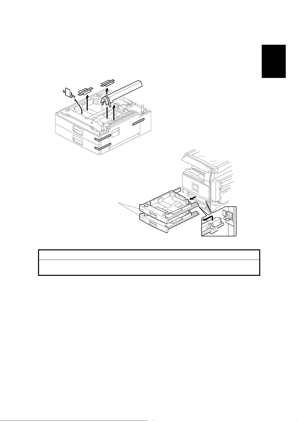
1. Unpack the paper tray unit.
2. Remove all tape and shipping materials.
3. Remove the paper trays [A].
1-19
Page 30
PAPER TRAY UNIT INSTALLATION (B542) 1 August, 2003
[B]
[F]
[E]
[A]
[D]
[J]
[C]
B542I113.W MF
[H]
[G]
B542I517.WMF
[I]
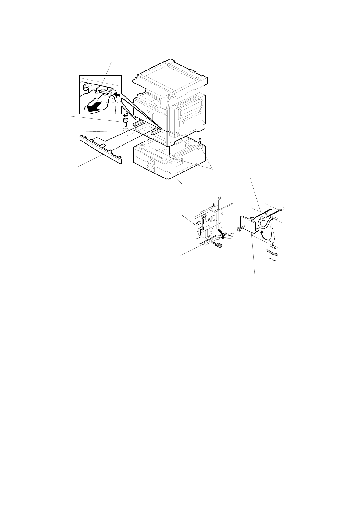
4. Remove the middle front cover [A] and pull out the front handles [B].
5. Using the front handles and rear handles, lift the machine and hold it over the
paper tray unit [C].
6. Slowly lower the machine onto the paper tray unit with the pegs [D] aligned with
the peg holes on the bottom of the machine.
NOTE: Do not hold the scanner unit.
7. Re-install the middle front cover [A].
8. Attach the spring washer [E] to the short knob screw [F]. Then, secure the
paper tray unit.
9. Open the right cover of the paper tray unit [G].
10. Secure the joint bracket [H] (1 long knob screw).
11. Remove the connector cover [I] of the main machine (! x 1).
12. Connect the paper tray unit harness [J] to the main machine and reinstall the
connector cover.
1-20
manuals4u.commanuals4u.com
Page 31

1 August, 2003 PAPER TRAY UNIT INSTALLATION (B542)
[A]
[A]
B542I118.W MF
Installation
[B]
B542I119.W MF
13. Install the front and rear stands [A] as shown above.
14. Install the stand bracket [B].
1-21
Page 32

PAPER TRAY UNIT INSTALLATION (B542) 1 August, 2003
[A]
[A]
B542I500.WMF
15. Load paper into the paper tray and install the paper trays.
16. Attach the appropriate tray decals [A] which are included in the accessory box
for the main machine.
17. Turn on the ac switch.
18. Turn the paper size dial to the correct setting for the paper size.
19. Check the machine’s operation and copy quality.
1-22
manuals4u.commanuals4u.com
Page 33

1 August, 2003 1-BIN TRAY UNIT INSTALLATION (B544)
1.5 1-BIN TRAY UNIT INSTALLATION (B544)
1.5.1 ACCESSORY CHECK
Check the quantity and condition of the accessories in the box against the following
list:
Description Q’ty
1. Ground Bracket..................................................................... 1
2. Connector Cover................................................................... 1
3. Base Cover ........................................................................... 1
4. Arm Cover............................................................................. 1
5. Copy Tray ............................................................................. 1
6. Mylar Strip............................................................................. 2
7. Stepped Screw – M3 x 8....................................................... 5
8. Screw –M3 x 8 ...................................................................... 2
9. Screw – M4 x 7 ..................................................................... 1
10. Tapping Screw – M3 x 6 ....................................................... 2
11. Tapping Screw – M3 x 14 ..................................................... 1
Installation
12. Tapping Screw – M3 x 8 ....................................................... 1
13. Installation Procedure ........................................................... 1
1-23
Page 34

1-BIN TRAY UNIT INSTALLATION (B544) 1 August, 2003
1.5.2 1-BIN TRAY INSTALLATION PROCEDURE
[A]
[B]
B544I113.WMF
!CAUTION
Unplug the main machine power cord before starting the following
procedure.
1. Remove Scanner Unit
NOTE: If the ARDF is installed, remove the ARDF before removing the
scanner unit.
1) Remove the connector cover [A].
2) Disconnect the scanner cable [B].
3) Remove the scanner unit [C] (! x 3).
[C]
B544I114.WMF
1-24
manuals4u.commanuals4u.com
Page 35

1 August, 2003 1-BIN TRAY UNIT INSTALLATION (B544)
[B]
[C]
[A]
Installation
[F]
[E]
B544I201.WMF
[D]
B544I102.WMF
2. Unpack the 1-bin tray unit and remove the tapes.
3. Remove the front bracket [A] (! x 1) and rear bracket [B] (! x 1) from the top
of the paper exit cover [C].
4. Remove the paper exit cover [C] (! x 4).
5. Cut away two covers [D] from the base cover [E].
6. Trim the edges so they are smooth.
7. Install the base cover [E] (! x 3: stepped screw).
8. Set the 1-bin tray unit [F] on the base cover and slide onto the heads of the
stepped screws.
1-25
Page 36

1-BIN TRAY UNIT INSTALLATION (B544) 1 August, 2003
[A]
[E]
[D]
[G]
[C]
[B]
B544I492.WMF
[F]
B544I103.WMF
9. Secure the 1-bin tray unit [A] (! x 1 M3 x14).
10. Remove the cover [B].
11. Install the grounding bracket [C] (! x 2 M3 x 6).
12. Connect the harness [D].
13. Install the connector cover [E] (! x 1 M3 x 8)
14. Re-install the front bracket [F] (! x 2 M4 x 7, M4 x 10) and the rear bracket [G]
(! x 1 M4 x 10).
1-26
manuals4u.commanuals4u.com
Page 37

1 August, 2003 1-BIN TRAY UNIT INSTALLATION (B544)
[A]
[B]
[E]
B544I493.WMF
Installation
[D]
15. Attach the copy tray
Bridge Unit (B538) has not been installed:
1) Secure [A] (stepped ! x 2) into the side of the 1-bin tray housing.
2) Attach the copy tray [B] to the stepped screws.
Bridge Unit (B538) has been installed
1) Open the cover of the bridge unit [C].
2) First, remove the copy tray bracket [D] (" x 1).
3) Install the copy tray bracket (! x 1: tapping screw).
4) Re-install the copy tray [E] (" x 1).
[C]
B544I501.WMF
1-27
Page 38

1-BIN TRAY UNIT INSTALLATION (B544) 1 August, 2003
[C]
[A]
[B]
B544I104.WMF
[D]
B544I500.WMF
16. Remove the scanner stand cover [A] (! x 2).
17. To adjust the height of the scanner stand, first remove [B] (! x 2) to release the
scanner stand [C].
18. Raise the scanner stand until the next set of screw holes in the main frame can
be seen through the screw holes in the scanner stand.
19. Secure the stand (! x 2: ➀, ➁) and install the arm cover [D] (! x 1).
1-28
manuals4u.commanuals4u.com
Page 39

1 August, 2003 1-BIN TRAY UNIT INSTALLATION (B544)
[B]
Installation
[A]
B544I106.WMF
20. Attach two mylar strips [A] to the scanner stand [B].
21. Reinstall the scanner stand cover.
22. Reinstall the scanner unit.
23. Turn on the main switch and check the 1-bin tray unit operation.
1-29
Page 40

BRIDGE UNIT INSTALLATION (B538) 1 August, 2003
1.6 BRIDGE UNIT INSTALLATION (B538)
1.6.1 ACCESSORY CHECK
Check the quantity and condition of the accessories in the box against the following
list:
Description Q’ty
1. Stepped Screw...................................................................... 2
2. Connector Cover ................................................................... 1
3. Exit Mylar .............................................................................. 2
4. Installation Procedure ........................................................... 1
1-30
manuals4u.commanuals4u.com
Page 41

1 August, 2003 BRIDGE UNIT INSTALLATION (B538)
1.6.2 BRIDGE UNIT INSTALLATION PROCEDURE
[A]
[D]
B538I401.WMF
Installation
[B]
B538I407.WMF
[C]
B538I500.WMF
!CAUTION
Unplug the main machine power cord before starting the following
procedure.
1. Unpack the bridge unit and remove all tapes shipping retainers.
2. Remove the inner tray [A].
3. On the side of the machine, remove the three small covers [B].
If the optional external output tray (A825) will be installed (instead of a
finisher), do Step 4.
[E]
4. Remove the two small covers [C].
5. Remove the cover [D] (! x 1).
6. Remove the cap [E].
1-31
Page 42

BRIDGE UNIT INSTALLATION (B538) 1 August, 2003
[A]
[E]
[D]
[B]
B538I402.WMF
[C]
B538I404.WMF
7. If an optional finisher is to be installed, attach two mylars [A] to the bridge unit.
8. Remove the cover [B].
9. Install the bridge unit [C] (! x 2).
10. Connect the bridge unit I/F harnesses [D] ($ x 2).
11. Install the connector cover [E].
12. Turn on the main switch and check the bridge unit operation (make sure that
there are no paper jams).
1-32
manuals4u.commanuals4u.com
Page 43

1 August, 2003 TWO-TRAY FINISHER INSTALLATION (B545)
1.7 TWO-TRAY FINISHER INSTALLATION (B545)
1.7.1 ACCESSORY CHECK
Check the quantity and condition of the accessories in the box against the following
list:
Description Q’ty
1. Front Joint Bracket................................................................ 1
2. Rear Joint Bracket ................................................................ 1
3. Shift Tray............................................................................... 2
4. Screw – M4 x 8 ..................................................................... 2
5. Screw – M4 x 12 ................................................................... 5
6. Ground Plate......................................................................... 1
7. Installation Procedure ........................................................... 1
Installation
1-33
Page 44

TWO-TRAY FINISHER INSTALLATION (B545) 1 August, 2003
1.7.2 TWO-TRAY FINISHER INSTALLATION PROCEDURE
[A]
B545I101.WMF
[C]
[B]
B545I107.WMF
!CAUTION
Unplug the main machine power cord before starting the following
procedure.
NOTE: The bridge unit (B538) and paper tray unit (B542) must be installed before
installing this finisher.
1. Unpack the finisher and remove all tapes and shipping retainers from outside
the unit [A].
2. Open the front door [B] and remove all tapes and shipping materials from inside
the finisher unit.
3. Save the retainer [C] and other shipping material.
NOTE: The retainer [C] must be re-installed in the finisher before moving or
shipping the finisher to another location.
1-34
manuals4u.commanuals4u.com
Page 45

1 August, 2003 TWO-TRAY FINISHER INSTALLATION (B545)
[A]
[B]
Installation
[C]
B545I104.WMF
[D]
B545I105.WMF
4. Install the left joint bracket [A] (! x 2 M4 x 12) and right joint bracket [B] (! x 2
M4 x 12).
5. Attach the ground plate [C] (! x 1 M4 x 12) to the center of the paper tray unit
as shown.
6. Open the front door of the finisher, and pull out the locking lever [D] (! x 1).
7. Push the finisher to the side of the machine with the holes in the finisher
aligned with the joint brackets, and then dock the finisher against the machine.
8. Push in the locking lever and secure it (! x 1), then close the front door.
1-35
Page 46

TWO-TRAY FINISHER INSTALLATION (B545) 1 August, 2003
[A]
B545I103.WMF
[B]
B545I106.WMF
9. Install two trays [A] (! x 1 each).
10. Connect the finisher cable [B] to the main machine below the right, rear handle.
11. Turn on the main switch and check the finisher operation.
1-36
manuals4u.commanuals4u.com
Page 47

1 August, 2003 PUNCH UNIT INSTALLATION
1.8 PUNCH UNIT INSTALLATION
1.8.1 ACCESSORY CHECK
Check the quantity and condition of the accessories in the box against the following
list:
Description Q’ty
1. Punch unit ............................................................................. 1
2. Sensor arm ........................................................................... 1
3. Hopper .................................................................................. 1
4. Step screw ............................................................................ 1
5. Spring.................................................................................... 1
6. Spacer (2 mm) ...................................................................... 1
7. Spacer (1 mm) ...................................................................... 1
8. Tapping screw....................................................................... 1
9. Tapping screw....................................................................... 2
Installation
1-37
Page 48

PUNCH UNIT INSTALLATION 1 August, 2003
1.8.2 PUNCH UNIT INSTALLATION PROCEDURE
[A]
B377I102.WMF
[C]
B377I103.WMF
!CAUTION
Switch off the main machine and unplug its power cord. If the Two-Tray
Finisher is installed, disconnect it and pull it away from the machine.
(☛1.7)
1. Unpack the punch unit and remove all tapes and shipping retainers.
[B]
2. Open the front door and remove the rear cover [A] (! x4).
3. Remove the bracket [B] (! x2) and paper guide [C] (! x 1).
1-38
manuals4u.commanuals4u.com
Page 49

1 August, 2003 PUNCH UNIT INSTALLATION
[B]
[A]
[C]
B377I101.WMF
[E]
Installation
4. Remove the hopper cover [A] (! x 2).
5. Install the sensor bracket [B] (stepped ! x 1).
6. Install the spring [C].
7. Install the 2 mm spacer [D].
8. Install the punch unit [E] (! x 2, stepped ! x 1)
1-39
B377I104.WMF
[D]
Page 50

PUNCH UNIT INSTALLATION 1 August, 2003
[A]
B377I105.WMF
[B]
B377I106.WMF
9. Connect the harnesses [A] and clamp them as shown.
NOTE: No special DIP switch settings are required for this punch unit. The
punch unit sends an identification signal to the machine board so it
knows what type of punch unit has been installed.
10. Slide the hopper [B] into the machine.
11. Fasten the two 1 mm spacers [C] to the rear frame for future adjustment.
NOTE: The spacers are used to adjust the horizontal positioning of the holes.
[C]
12. Reassemble the finisher and check the punch operation.
1-40
manuals4u.commanuals4u.com
Page 51

1 August, 2003 ARDF INSTALLATION (B541)
1.9 ARDF INSTALLATION (B541)
1.9.1 ACCESSORY CHECK
Check the quantity and condition of the accessories in the box against the following
list:
Description Q’ty
1. Stepped Screw...................................................................... 2
2. Screw – M4 x 10 ................................................................... 2
3. Attention Decal - Scanner ..................................................... 1
4. Attention Decal – Top Cover ................................................. 1
5. Installation Procedure ........................................................... 1
1.9.2 ARDF INSTALLATION PROCEDURE
Installation
B541I904.WMF
!CAUTION
Unplug the main machine power cord before starting the following
procedure.
1. Unpack the ARDF and remove all tapes and shipping retainers.
1-41
Page 52

ARDF INSTALLATION (B541) 1 August, 2003
[B]
[C]
[A]
B541I905.WMF
[D]
B541I124.WMF
2. Attach and tighten [A] (! x 2 stud).
3. Mount the ARDF by aligning the screw keyholes [B] of the ARDF support plate
over the stud screws, and slide the ARDF toward the front of the machine.
NOTE: To avoid damaging the ARDF, hold it as shown in the illustration.
4. Secure the ARDF [C] (! x 2).
5. Connect the I/F cable [D] ($ x 1) to the main machine.
1-42
manuals4u.commanuals4u.com
Page 53

1 August, 2003 ARDF INSTALLATION (B541)
[B]
Installation
[A]
B541I901.WMF
B541I902.WMF
[C]
[E]
B541I906.WMF
B541I903.WMF
6. Peel off the platen sheet [A] and place it on the exposure glass.
7. Line up the rear left corner of the platen sheet flush against corner [B] on the
exposure glass.
[D]
8. Close the ARDF.
9. Attach the decal [C] to the top cover as shown, choosing the language most
suitable for the machine installed.
10. Attach the decal [D] to the cover so that the arrow on the decal lines up with the
groove [E] of the left scale as shown. As with step 9, choose the language most
suitable for the machine installed.
11. Turn on the main switch.
12. Check the ARDF operation and copy quality. Be sure to check and adjust the
registration for the ARDF with the SP modes
1-43
Page 54

ARDF INSTALLATION (B541) 1 August, 2003
1.9.3 ARDF SKEW ADJUSTMENT
[B]
[C]
[A]
B541I907.WMF
1. Remove the tape [A] covering the elliptical hole.
2. Remove right screw [B] and install it into the elliptical hole [C].
3. Move the right side of the ARDF forward or back to adjust the position then
tighten the screw.
1-44
manuals4u.commanuals4u.com
Page 55

1 August, 2003 LCT INSTALLATION (B543)
1.10 LCT INSTALLATION (B543)
1.10.1 ACCESSORY CHECK
Check the quantity and condition of the accessories in the box against the following
list:
Description Q’ty
1. Joint Pin ................................................................................ 2
2. Stepped Screw M3 x 18........................................................ 4
3. Magnet Cover ....................................................................... 1
4. NECR (-17, -27 machines).................................................... 1
5. Installation Procedure ........................................................... 1
Installation
1-45
Page 56

LCT INSTALLATION (B543) 1 August, 2003
1.10.2 LCT INSTALLATION PROCEDURE
[C]
[B]
[A]
B543I504.WMF
!CAUTION
Unplug the main machine power cord before starting the following
procedure.
NOTE: The Paper Tray Unit (B542) must be installed before installing the LCT.
1. Unpack the LCT and remove the tapes.
2. Open the right cover of the paper tray unit [A].
3. Open the lower right cover [B] and cut the holding band [C].
NOTE: When cutting the holding band, the upper part of the band should be
cut as shown. Otherwise, paper jams may occur.
4. Remove the lower right cover.
1-46
manuals4u.commanuals4u.com
Page 57

1 August, 2003 LCT INSTALLATION (B543)
[A]
[E]
Installation
[B]
[D]
[C]
B543I503.WMF
6. Install the joint pins [A].
7. Push the release lever [B] and slide the LCT to the right (front view).
8. Hang the LCT [C] on the joint pins, then secure the brackets [D] (! x 4).
9. Return the LCT to the previous position and connect the LCT cable [E].
10. Open the LCT cover and load the paper.
11. Turn on the ac switch and check the LCT operation.
1-47
Page 58

PLATEN COVER INSTALLATION (G329) 1 August, 2003
1.11 PLATEN COVER INSTALLATION (G329)
[C]
[B]
[A]
[A]
B135I904.WMF
1. Install [A] (! x 2) on the top cover as shown.
2. Position the platen cover bracket [B] on the heads of the stud screws and slide
the platen cover [C] to the left.
1-48
manuals4u.commanuals4u.com
Page 59

1 August, 2003 BOOKLET FINISHER INSTALLATION (B546)
1.12 BOOKLET FINISHER INSTALLATION (B546)
1.12.1 ACCESSORY CHECK
Check the quantity and condition of the accessories in the box against the following
list.
7
5
4
2
9
1
10
6
3
8
B546I101.WMF
Installation
Description Q’ty
1. Upper Tray.......................................................................... 1
2. Shift Tray............................................................................. 1
3. Tapping Screw - M4 x 6...................................................... 2
4. Rail Ass’y ............................................................................ 1
5. Joint Bracket ....................................................................... 1
6. Tapping Screw - M4 x 16 .................................................... 8
7. Rail Bracket......................................................................... 1
8. Tapping Screw - M4 x 6...................................................... 1
9. Harness Cover.................................................................... 1
10. Sensor Feeler ................................................................... 1
1-49
Page 60

BOOKLET FINISHER INSTALLATION (B546) 1 August, 2003
1.12.2 BOOKLET FINISHER INSTALLATION PROCEDURE
B546I102.WMF
B546I104.WMF
!CAUTION
Keep the power cord unplugged when starting the following procedure.
1. Unpack the finisher and remove the tapes and shipping retainers.
1-50
manuals4u.commanuals4u.com
Page 61

1 August, 2003 BOOKLET FINISHER INSTALLATION (B546)
[A]
[B]
B546I105.WMF
[E]
Installation
[D]
2. Open the front under door and pull out the staple unit [A].
3. Remove the stapler unit lock plate [B] (! x 1).
4. Push in the stapler unit and shut the front lower door.
5. Remove the right lower cover [C] (! x 4).
6. Remove the front pressure release bracket [D] (! x 1).
7. Remove the rear pressure release bracket [E] (! x 1).
8. Reattach the cover [C].
[C]
B546I103.WMF
1-51
Page 62

BOOKLET FINISHER INSTALLATION (B546) 1 August, 2003
[A]
[B]
[C]
B546I106.WMF
[D]
B546I107.WMF
9. Set the hooks [A] of the shift tray [B] in the notches in the shift tray bracket, and
secure the tray with two M4 x 6 screws.
10. Connect the shift tray sensor harness [C].
11. Install the harness cover [D] (2 hooks).
1-52
manuals4u.commanuals4u.com
Page 63

1 August, 2003 BOOKLET FINISHER INSTALLATION (B546)
[A]
Installation
[C]
B546I108.WMF
[B]
B546I801.WMF
[E]
[D]
[F]
B546I921.WMF
12. Install the upper tray [A] (2 pins).
13. Attach the sensor feeler [B] (2 pins).
14. Remove the stand bracket [C].
15. Attach the rail [D] to the rail bracket [E] as shown.
16. Install the rail bracket [F] on the left lower cover of the copier (! x 4).
1-53
Page 64

BOOKLET FINISHER INSTALLATION (B546) 1 August, 2003
[A]
[C]
[D]
B546I920.WMF
[B]
B5 46I 111. WMF
17. Install the joint bracket [A] on the left side of the copier (! x 4).
18. Secure the rail [B] to the booklet finisher with 1 M4 screw.
19. Align the finisher on the joint bracket and lock the 2 hooks [C] of the finisher on
the joint bracket.
20. Connect the finisher cable [D] to the copier.
21. Turn on the main switch and check the finisher operation.
1-54
manuals4u.commanuals4u.com
Page 65

1 August, 2003 1000 SHEET FINISHER (B408)
1.13 1000 SHEET FINISHER (B408)
1.13.1 ACCESSORY CHECK
Check the quantity and condition of the accessories against the following list.
6
2
1
7
8
5
4
3
10
9
B408I502.WMF
Description Q’ty
1 Front Joint Bracket............................................................... 1
*1
2 Rear Joint Bracket
............................................................ 1
Installation
3 Rear Joint Bracket ............................................................... 1
4 Grounding Plate................................................................... 1
5 Copy Tray ............................................................................ 1
6 Staple Position Decal........................................................... 1
7 Screw - M4 x 14................................................................... 4
8 Knob Screw - M4 x 10.......................................................... 1
9 Screw - M3 x 8..................................................................... 1
10 Knob Screw - M3 x 8.......................................................... 1
*1
: Rear joint bracket is not required for these models.
1-55
Page 66

1000 SHEET FINISHER (B408) 1 August, 2003
1.13.2 1000 SHEET FINISHER INSTALLATION PROCEDURE
[A]
B408I102.WMF
!CAUTION
Unplug the main machine power cord before starting the following
procedure.
1. The following options must be installed before installing this finisher.
- Bridge Unit (B538)
- Paper Tray Unit (B542)
2. Unpack the finisher and remove the tapes.
NOTE: Be sure to keep screw [A]. It will be needed to secure the grounding
plate in Step 3.
B408I103.WMF
1-56
manuals4u.commanuals4u.com
Page 67

1 August, 2003 1000 SHEET FINISHER (B408)
[B]
[G]
Installation
[A]
[F]
[E]
B408I503.WMF
[C]
[D]
B408I201.WMF
B408I504.WMF
2. Install the front joint bracket [A] (2 screws - M4 x 14) and rear joint bracket [B]
(! x 2 M4 x 14).
3. Install the grounding plate [C] to the finisher (! x 2 M3 x 8).
NOTE: Use the screw removed in step 1 and the screw from the accessory
box.
4. Open the front door [D] then pull the locking lever [E].
5. Align the finisher on the joint brackets, and lock it in place by pushing the
locking lever.
6. Secure the locking lever (! x 1 knob screw M3 x 8).
7. Close the front door.
8. Install the copy tray [F] (! x 1 knob screw M4 x 10).
9. Connect the finisher cable [G] to the main machine below the right rear handle.
1-57
Page 68

1000 SHEET FINISHER (B408) 1 August, 2003
[A]
B408I501.WMF
10. Attach the staple position decal [A] to the ARDF as shown.
11. Turn on the main power switch and check the finisher operation.
1-58
manuals4u.commanuals4u.com
Page 69

1 August, 2003 FILE FORMAT CONVERTER B519-17
1.14 FILE FORMAT CONVERTER B519-17
1.14.1 ACCESSORY CHECK
1. File Format Converter Board ......................................... 1
1.14.2 INSTALLATION PROCEDURE
!CAUTION
Switch the machine off and unplug the main machine power cord before
starting the following procedure.
[D]
[A]
Installation
[C]
B519I501.WMF
1. Remove the left corner cover (! x 2).
[B]
2. Remove the rear upper cover (! x 2).
3. Remove the rear lower cover (! x 4).
4. Remove the controller box [A] (! x 2).
5. Remove the two screws [B] from the controller board.
6. Use the screws removed in the previous step to attach the File Format
Converter board [C] to the controller board [D] (! x 2)
7. Reattach the controller box and covers.
B519I502.WMF
1-59
Page 70

FILE FORMAT CONVERTER B519-17 1 August, 2003
1.14.3 CHECK ALL CONNECTIONS
1. Plug in the power cord and turn on the main switch.
2. Enter the printer user mode and print the configuration page.
User Tools> Printer Settings> List Test Print> Config. Page
NOTE: The same data can also be printed by executing SP1-004 – Print
Summary. All installed options are listed in the “System Reference”
column.
1-60
manuals4u.commanuals4u.com
Page 71

1 August, 2003 PM TABLE
2. PREVENTIVE MAINTENANCE SCHEDULE
2.1 PM TABLE
NOTE: Amounts mentioned as the PM interval indicate the number of prints.
Symbol key: C: Clean, R: Replace, L: Lubricate, I: Inspect
B135/B138 EM 150K 300K 450K NOTE
SCANNER/OPTICS
Reflector C C C Optics cloth
1st Mirror C C C Optics cloth
2nd Mirror C C C Optics cloth
3rd Mirror C C C Optics cloth
Scanner Guide Rails
Platen Sheet Cover
Exposure Glass C C C Dry cloth or alcohol
Toner Shield Glass C C C Optics cloth
APS Sensor C C C Dry cloth or alcohol
Exposure Glass (Sheet
through)
DRUM (OPC) AREA
Charge Roller R R R
Charge Roller Cleaning
Roller
Drum Cleaning Blade 1 R R R
Drum Cleaning Blade 2 R R R
Quenching Lamp C Dry cloth
Pick-off Pawls R R R
Spurs C C C Dry cloth or alcohol
ID Sensor
Cleaning Entrance Seal
Side Seal I I I
I I I
C I I I
C C C
R R R
C C C
C C C
Do not use alcohol. Lubricate
if necessary.
Dry cloth or alcohol. Replace
platen sheet if required.
Dry cloth or alcohol
Perform SP3-001-2 after
blower brush cleaning.
Blower brush. Replace if
required.
Preventive
Maintenance
2-1
Page 72

PM TABLE 1 August, 2003
B003/B004B006/B007 EM 150K 300K 450K NOTE
DEVELOPMENT UNIT
Development Drive
Gears
I I I
Development Filter R R R
Developer I R I
Entrance Seal I I I
Side Seal I I I
Development Roller C C C Dry cloth
PAPER FEED
Registration Roller C C C C Water or alcohol.
Idle Roller Dust Blade
C C C
Detach and tap gently on flat
surface to empty. Blower
brush.
Registration Roller Dust
Blade
C R C
Paper Feed Roller I R R R
Separation Roller I R R R
Pick-up Roller I R R R
Paper Feed Roller (By-
pass feed table)
Separation Roller (By-
pass feed table)
Pick-up Roller
(By-pass feed table)
I R R R
I R R R
I R R R
Blower brush.
Check counter value for
each (SP7-204). If ≥ 150 K,
replace roller. After replacing
the roller, do SP7-816 to
reset counter.
Paper Feed Guides C C C Water or alcohol.
Relay Rollers C C C Water or alcohol.
Bottom Plate Pad C C C Water or alcohol.
Bottom Plate Pad (By-
pass feed)
C C C
Water or alcohol.
Registration Sensor C C C Blower brush
Paper Feed Roller Gear
L L L
Silicone Grease G-501. See
note below.*
1
Upper Relay Sensor C C C Blower Brush
DUPLEX UNIT
Upper Transport Roller C C C Water or alcohol.
Lower Transport Roller C C C Water or alcohol.
TRANSFER BELT UNIT
Transfer Belt C R R R Dry cloth
Transfer Belt Cleaning
Blade
R R R
Transfer Belt Rollers C C C Dry cloth
Entrance Seal C C C Dry cloth
Transfer Entrance
Guide
C C C C
Dry cloth
Used Toner Tank I C C C Empty the tank.
2-2
manuals4u.commanuals4u.com
Page 73

1 August, 2003 PM TABLE
B135/B138 EM 150K 300K 450K NOTE
FUSING UNIT AND PAPER EXIT
Fusing Entrance and
Exit Guide Plates
C C C
Water or alcohol.
Hot Roller R R R
Pressure Roller R R R
Fusing Thermistors R R R
Cleaning Roller R R R
Cleaning Roller
Bushings
L L L
Grease: Barrierta JFE 55/2
Hot Roller Strippers C R C Water or alcohol.
Paper Exit Guide Ribs
C C C
Water or alcohol. (See
illustration below.)
Exit Sensor C C C Blower brush
DRIVE
Drive Belts I Replace if necessary
Clean here.
Preventive
Maintenance
B135P901.WMF
B541 EM 80K 160K 240K NOTE
ARDF (for originals)
Pick-up Roller C R R R Belt cleaner
Feed Belt C R R R Belt cleaner
Separation Roller C R R R Dry or damp cloth
Sensors C C C Blower brush
Drive Gears L L L Grease, G501
B542 EM 150K 300K 450K NOTE
PAPER TRAY UNIT
Paper Feed Rollers R R R
Pick-up Rollers R R R
Separation Rollers
R R R
Check counter with SP7-204. If
≥ 150 K, replace roller. After
replacing the roller, do SP7-816
to reset counter.
Relay Rollers C C C Dry or damp cloth
Bottom Plate Pad C C C Dry or damp cloth
2-3
Page 74

PM TABLE 1 August, 2003
B543 EM 150K 300K 450K NOTE
LCT
Paper Feed Roller
R R R
Check counter with SP7-204. If
≥ 150 K, replace roller. After
replacing the roller, do SP7-816
to reset counter.
Pick-up Roller R R R
Separation Roller R R R
Bottom Plate Pad C C C Dry or damp cloth
B408/B545 EM 150K 300K 450K NOTE
1000-SHEET/TWO-TRAY FINISHER
Rollers C Water or alcohol.
Brush Roller
(A681 only)
I I I I
Replace if required.
Discharge Brush C C C C Dry cloth
Sensors C Blower brush
Jogger Fences I I I I Replace if required.
Punch Waste Hopper* I I I I Empty hopper.
*: Only for B545
B546 EM 150K 300K 450K NOTE
BOOKLET FINISHER
Transport Belt C C C
Stapler Paddles C C C
B544 EM 150K 300K 450K NOTE
1-BIN TRAY UNIT
Rollers C Dry or damp cloth
Copy Tray C Dry or damp cloth
Sensors C Blower brush
*1
: Lubricate the paper feed clutch gear [A]
with Silicone Grease G501 every P.M.
[A]
2-4
manuals4u.commanuals4u.com
B135P900.WMF
Page 75

1 August, 2003 SPECIAL TOOLS AND LUBRICANTS
3. REPLACEMENT AND ADJUSTMENT
New design changes have been implemented in order to accommodate the new
PxP (Polyester Polymerization) toner, which is of smaller particle size and allows
lower fusing temperatures. This section describes some of these design changes
and how they affect replacement and adjustment procedures.
PCU
• New cleaning blade: The PCU (Photoconductor Unit) must handle finer toner,
so in addition to the stationary drum cleaning blade, a spring-loaded blade has
been added for drum cleaning. The additional cleaning blade is required for the
finer toner, and a new procedure for removal has been added. (☛ Drum
Cleaning Blade)
• Charge roller replacement: The standard voltages for SP2001 1 have changed
and must be checked after charge roller replacement.
Fusing Unit
The fusing unit can be operated at a lower temperature for the finer toner because
it melts easily, so the following changes have been made in the fusing unit:
Adjustment
Replacement
• Cooling fans: Two cooling fans have been added around the fusing unit, one on
the right side of the machine and another on the right corner. Two new removal
procedures have been added. (☛ 3.4.2, 3.4.3)
• Hot roller knob: The size of the knob on the end of the fusing unit is larger,
making the roller easier to turn manually. (☛ 3.4.1)
Other Changes
While the following are not related to the new toner, they are nonetheless important
changes:
• Toner shield glass cover: The shield glass is now equipped with a cover that
locks the glass in place and prevents the shield glass from sliding out of the
machine accidentally. (☛ 3.2.2)
• Dust blades: Two new paper dust blades have been added around the
registration roller to clean paper dust from the paper feed path. Both blades can
be easily removed and cleaned. (☛ 3.5.1, 3.5.2)
• IOB: The IOB (I/O Interface Board) has been moved from inside the machine to
under the rear lower cover, making access much easier. (☛ 3.6.1)
• Flash memory cards: The number designations for the flash memory cards
have changed. (☛3.1.1)
3-1
Page 76

SPECIAL TOOLS AND LUBRICANTS 1 August, 2003
3.1 SPECIAL TOOLS AND LUBRICANTS
3.1.1 SPECIAL TOOLS
Part Number Description Q’ty
A2309003 Adjustment Cam – Laser Unit 1
A2309004 Positioning Pin – Laser Unit 1
N8036701 Flash Memory Card – 4MB 1
N8031000 Case – Flash Memory Card 1
A0069104 Scanner Positioning Pin (4 pcs/set) 1
A2929500 Test Chart – S5S (10 pcs/Set) 1
G0219350 Parallel Loopback Connector 1
3.1.2 LUBRICANTS
Part Number Description Q’ty
A2579300 Grease Barrierta S552R 1
52039502 Silicone Grease G-501 1
3-2
manuals4u.commanuals4u.com
Page 77

1 August, 2003 LASER UNIT
3.2 LASER UNIT
WARNING
!
Turn off the main power switch and unplug the machine before attempting
any of the procedures in this section. Laser beams can seriously damage
your eyes.
3.2.1 CAUTION DECAL LOCATIONS
Two caution decals are located in the laser section as shown below. (See the next
page for removal instructions.)
Adjustment
Replacement
A232R500.CDR
LASER-1.WMF
LASER-2.WMF
LASER-3.WMF
3-3
Page 78

LASER UNIT 1 August, 2003
3.2.2 LASER UNIT
[C]
[A]
[B]
[D]
[E]
B135R901.WMF
[B]
!WARNING
Turn off the main power switch and unplug the machine before attempting
this procedure. Laser beams can seriously damage your eyes.
1. Open the front door and raise the toner bottle holder handle [A].
2. Front door (pins [B] x 2)
3. Inner cover [C] (! x 2, " x 1)
4. Shield glass cover [D].
The shield glass cover holds the shield glass firmly in place and prevents it
from accidental removal.
To remove, on the left side press in the top leaf and pull off.
When re-attaching the shield glass cover, note that the top leaf lies on top of
the plastic form.
5. Shield glass [E]
3-4
manuals4u.commanuals4u.com
Page 79

1 August, 2003 LASER UNIT
[B]
[C]
Adjustment
Replacement
[A]
6. Shield plate [A] (! x 2)
7. Laser unit connectors [B] (" x 6, " x1 flat cable)
NOTE: Hold the LD board securely when disconnecting connectors.
8. Laser unit [C] (! x 2)
NOTE: When sliding out the laser unit, do not hold the LD board. Hold the
laser unit casing.
B135R902.WMF
3-5
Page 80

PHOTOCONDUCTOR UNIT (PCU) 1 August, 2003
3.3 PHOTOCONDUCTOR UNIT (PCU)
3.3.1 PCU
[C]
[A]
[B]
B135R903.WMF
[D]
[E]
B135R904.WMF
1. Open the front door.
2. Lower the by-pass tray, open the duplex unit, and open the transfer unit right
cover.
3. Spread a sheet of A4 or LTR size paper [A] on top of the open front door.
NOTE: This paper catches any loose toner that may fall from the PCU as it is
removed.
4. Loosen [B] (! x 1).
5. Rotate bracket [C] to the left.
6. Raise the release lever [D].
7. Hold the PCU [E] as shown and pull it out of the machine.
NOTE: If the right cover is to be left open, cover the drum with paper, or
remove the PCU and cover it with paper. Before you re-install the PCU,
align the brackets on the PCU with the rails above and make sure they
are engaged before you slowly push the PCU into the machine.
3-6
manuals4u.commanuals4u.com
Page 81

1 August, 2003 PHOTOCONDUCTOR UNIT (PCU)
3.3.2 DRUM
[B]
[A]
B135R905.WMF
Adjustment
Replacement
[C]
1. Remove the PCU (☛3.3.1)
2. Toner cap [A]
3. Insert cap [A] into the toner entrance hole [B].
NOTE: Make sure that the cap is inserted completely into the hole.
4. On the left side of the PCU, disconnect the
spring [C].
3
5. On the right side of the PCU disconnect the
spring [D] and attach it to hooks as shown.
• To prevent breaking the weaker hook
a pair of needle-nose pliers to disconnect the
spring at
➁, then re-attach to ➁ and ➂.
➀, use
2
• Moving this spring retracts the movable drum
cleaning blade so it does not touch the
surface of the drum when the drum is re-
1
installed.
[D]
B135R906.WMF
3
2
1
B135R907.WMF
3-7
Page 82

PHOTOCONDUCTOR UNIT (PCU) 1 August, 2003
[A]
[B]
B135R908.WMF
B135R909.WMF
[D]
[C]
6. Turn the PCU upside-down, and remove lower PCU cover [A] (! x 2, 3 pawls).
7. Pull the drum [B] towards the front
releasing the charge roller [C] using the release lever
the drum
➂.
➁ (the left side in the illustration) while
➀ [D], and then remove
CAUTION: Never touch the drum surface with bare hands.
8. Replace the drum and re-attach the lower PCU cover.
9. Detach the spring from ➁, ➂and re-attach to ➀,
➁
.
3
3
CAUTION: You must return re-attach the spring
➀, ➁ in order for the cleaning
to
blade to operate correctly.
2
2
If you fail to re-attach the spring to ➀, ➁ the
movable cleaning blade will not contact the
drum for cleaning, but the machine will operate
without generating an error. However, copies
will gradually become dirty due to toner
1
B135R910.WMF
1
collecting on the drum.
10. Re-attach the spring on the left side of the PCU.
11. After replacing the drum, perform the ID sensor initial setting using SP3001
002.
12. Do the process initial setting procedure (SP2805).
3-8
manuals4u.commanuals4u.com
Page 83

1 August, 2003 PHOTOCONDUCTOR UNIT (PCU)
3.3.3 PICK-OFF PAWLS
[A]
Adjustment
Replacement
[B]
B135R911.WMF
1. Remove the drum. (☛ 3.3.2)
2. Pawl assembly [A]
3. Pick-off pawl [B] (spring x 1, spur x 1)
Pick-off pawl position adjustment
If the pick-off pawl has marked the drum with a line, the pick-off pawl position can
be adjusted using either method:
• Changing the spur position.
• Changing the pick-off pawl assembly position
CAUTION: After re-assembly make sure that the front spring of the movable
cleaning blade is re-attached to the
➀, ➁ position. (☛ 3.3.2)
3-9
Page 84

PHOTOCONDUCTOR UNIT (PCU) 1 August, 2003
3.3.4 CHARGE ROLLER AND CLEANING ROLLER
[D]
[B]
[A]
[E]
B135R912.WMF
[C]
1. Remove the drum. (☛ 3.3.2)
2. Two snap rings [A] (# x 2).
3. Push charge roller holder [B] toward the front of the PCU and remove the
spring [C].
4. Charge roller [D].
NOTE: Disengage the charge roller on the right side to remove. Try to avoid
touching the charge roller.
5. Cleaning roller [E].
NOTE: Disengage the cleaning roller on the left to remove.
6. After replacing the charge roller and cleaning roller, check the value of SP2001
001. If it is not at the standard value (1450 V), set SP2001 001 to –1450 V.
NOTE: If this is not done, the carrier will be attracted to the drum because the
charge roller voltage will be too high.
CAUTION: After re-assembly make sure that the front spring of the movable
cleaning blade is re-attached to the ➀, ➁ position. (☛ 3.3.2)
3-10
manuals4u.commanuals4u.com
Page 85

1 August, 2003 PHOTOCONDUCTOR UNIT (PCU)
3.3.5 DRUM CLEANING BLADE 2
[D]
[B]
[A]
Adjustment
Replacement
B135R913.WMF
[C]
1. Remove the OPC drum. (☛ 3.3.2)
2. Remove the charge roller and cleaning roller. (☛ 3.3.4)
3. Remove the movable cleaning blade [A]. (# x 1)
Re-installation
• Engage the left end of the cleaning blade first, then make sure that both arms [B]
and [C] are through the holes on the left and right side.
• When you re-attach the snap-ring, make sure that the head of the snap ring [D] is
below the blade.
CAUTION: After re-assembly make sure that the front spring of the movable
cleaning blade is re-attached to the
➀, ➁ position. (☛ 3.3.2)
3-11
Page 86

PHOTOCONDUCTOR UNIT (PCU) 1 August, 2003
3.3.6 DRUM CLEANING BLADE 1
[A]
B135R929.WMF
1. Remove the drum. (☛ 3.3.2)
2. Remove the charge roller and cleaning roller. (☛ 3.3.4)
3. Remove the movable cleaning blade. (☛ 3.3.5)
4. Remove the stationary drum cleaning blade [A] (! x 2)
CAUTION: After re-assembly make sure that the front spring of the movable
cleaning blade is re-attached to the
➀, ➁ position. (☛ 3.3.2)
3-12
manuals4u.commanuals4u.com
Page 87

1 August, 2003 FUSING UNIT
3.4 FUSING UNIT
CAUTION
!
Allow time for the unit to cool before doing the following procedure.
3.4.1 FUSING UNIT REMOVAL
[B]
[C]
Adjustment
Replacement
[A]
[D]
B135R915.WMF
1. Open the front door, duplex unit, and right door.
2. Set screw [A] (! x 1)
3. Fusing unit release lever [B]
4. Slide out the fusing unit [C]
NOTE: A larger knob [D] is provided to make turning the hot roller easier to free
jams.
3-13
Page 88

FUSING UNIT 1 August, 2003
3.4.2 FUSING UNIT SIDE FAN
[A]
[B]
B135R916.WMF
1. Open the duplex unit and right door.
2. Release the transfer unit [A] and remove it.
3. Remove the shaft cover [B] (! x 3).
3-14
manuals4u.commanuals4u.com
B135R917.WMF
Page 89

1 August, 2003 FUSING UNIT
[A]
B135R918.WMF
Adjustment
Replacement
[C]
[B]
4. Separate the fan connectors [A] (" x 1).
NOTE: When re-connecting, be sure the thread the connector correctly
between the gaps.
5. Close the right door.
6. Use a short screwdriver to remove the fan plate [B] (! x 2).
7. Pull the fan [C] out of the machine.
B135R919.WMF
3-15
Page 90

FUSING UNIT 1 August, 2003
3.4.3 FUSING UNIT CORNER FAN
[A]
B135R920.WMF
[C]
1. Open the front door.
2. Open the duplex unit and right door.
3. Remove the fusing unit. (☛ 3.4.1)
4. Remove the magnet lock [A] of the front door (! x 2).
5. Remove the fan bracket [B] (! x 2).
6. Remove the fan [C] from the bracket (! x 2).
B135R921.WMF
[B]
3-16
manuals4u.commanuals4u.com
Page 91

1 August, 2003 PAPER FEED
3.5 PAPER FEED
3.5.1 IDLE ROLLER DUST BLADE
[A]
Adjustment
Replacement
B135R922.WMF
1. Open the duplex unit and right door.
2. Detach the dust blade [A].
3. Spread some paper on a flat surface and tap the dust blade gently to remove
paper dust collected in its dust box.
3-17
Page 92

PAPER FEED 1 August, 2003
3.5.2 REGISTRATION ROLLER DUST BLADE
[A]
B135R923.WMF
[B]
[C]
1. Open the duplex unit and open the right door.
2. Remove the PCU. (☛3.3.1)
3. Remove the development unit [A].
4. Press the top of the blade [B] to unlock it and open it to the left.
5. Remove the dust blade [C] from the machine.
B135R924.WMF
3-18
manuals4u.commanuals4u.com
Page 93

1 August, 2003 PRINTED CIRCUIT BOARDS
3.6 PRINTED CIRCUIT BOARDS
3.6.1 IOB
Adjustment
Replacement
[A]
B135R925.WMF
[B]
B135R926.WMF
1. Remove the rear lower cover [A] (! x 4).
2. Remove the IOB [B] (" All, ! x 4, Ribbon cable x 1).
3. The IOB is identical for the B135/B138. However, the DIP switches are set
differently for each machine. Check the DIP switches then adjust settings as
required. (See next page.)
3-19
Page 94

PRINTED CIRCUIT BOARDS 1 August, 2003
IOB DIP Switch Settings (SW101)
1. The position of SW 1 determines the engine speed. This switch should be UP
(ON) for the B135 (35 cpm) or DOWN (OFF) for the B138 (45 cpm)
NOTE: Move a switch UP to ON or DOWN to OFF.
2. SW 2, 3, 4, and 5 should all be DOWN (OFF). Do not change these settings.
This information is only for reference:
SW If set to ON
2 Switches off jam detection.
3 Engine program recovery.
4 Print output for debugging.
5 Checking duplex function at the factory.
3. SW 6, 7, 8 should be set for the area where the machine is used and serviced.
6 7 8 Location
OFF OFF OFF Japan
ON OFF OFF North America
OFF ON OFF Europe
OFF OFF ON China
ON OFF ON Taiwan
ON ON OFF Asia
OFF ON ON Korea
ON ON ON Not used
ON: Up
OFF: Down
3-20
manuals4u.commanuals4u.com
Page 95

1 August, 2003 HARD DISK, CONTROLLER BOARD
3.7 HARD DISK, CONTROLLER BOARD
NOTE: The controller boards are machine specific, i.e. the controller board for the
B135 (35 cpm) must be installed in the B135 copier, and the controller
board for the B138 (45 cpm) must be installed in the B138 copier. These
controller boards are not interchangeable.
[A]
[C]
Adjustment
Replacement
B135R927.WMF
1. Controller board [A] (! x 2)
NOTE: Use the wire handle to slide the HDD out of the expansion box.
2. HDD unit bracket [B] (! x 3, " x 2)
[B]
B135R928.WMF
3. HDD unit [C] (! x 4)
NOTE: Work carefully to avoid dropping or hitting the HDD.
After replacing the HDD, execute SP 5853 to copy the stamp data from the
firmware ROM to the new disk. No flash card is needed.
3-21
Page 96

1 August, 2003 SERVICE CALL CONDITIONS
4. TROUBLESHOOTING
!CAUTION
Never turn off the main power switch when the power LED is lit or flashing.
To avoid damaging the hard disk or memory, press the operation power
switch to switch the power off, wait for the power LED to go off, and then
switch the main power switch off.
NOTE: The main power LED lights or flashes while the platen cover or ARDF is
open, while the main machine is communicating with a facsimile or the
network server, or while the machine is accessing the hard disk or memory
for reading or writing data.
4.1 SERVICE CALL CONDITIONS
4.1.1 SUMMARY
There are 4 levels of service call conditions.
Trouble-
Level Definition Reset Procedure
A
B
C
D
To prevent damage to the machine, the main
machine cannot be operated until the SC has
been reset by a service representative (see the
note below).
If the SC was caused by incorrect sensor
detection, the SC can be reset by turning the
main power switch off and on.
The main machine can be operated as usual,
excluding the unit related to the service call.
The SC history is updated. The machine can be
operated as usual.
Enter SP mode, and then turn
the main power switch off and
on.
Turn the operation switch and
main power switch off and on.
Turn the operation switch off
and on.
The SC will not be displayed.
Only the SC history is updated.
shooting
NOTE: 1) If the problem concerns electrical circuit boards, first disconnect then
reconnect the connectors before replacing the PCBs.
2) If the problem concerns a motor lock, first check the mechanical load
before replacing motors or sensors.
4-1
manuals4u.commanuals4u.com
Page 97

SERVICE CALL CONDITIONS 1 August, 2003
4.1.2 SC CODE DESCRIPTIONS
NOTE: This is a list of the new and revised SC codes for the B135 (35 cpm) and
B138 (45 cpm) machines. For details about other SC codes please refer to
Service Manual of the previous models.
Code No. Symptom Possible Cause
320 C
(Deleted)
335
(New)
336
(New)
337
(New)
338
(New)
450
(New)
520
(New)
C
C
C
C
C
C
Polygon motor error
Polygonal Mirror Motor Error 1: ON
Timeout
The XSCRDY signal is not issued
(LOW: Active) within 25 s after the
polygonal mirror motor switches on.
Polygonal Mirror Motor Error 2: OFF
Timeout
The XSCRDY signal is not issued
(HIGH: Inactive) within 2 s after the
polygonal mirror motor switches off.
Polygonal Mirror Motor Error 3:
XSCRDY Signal Error
The XSCRDY is not issued (HIGH:
Inactive) after the polygonal mirror
motor has been rotating normally for
600 ms.
Polygonal Mirror Motor Error 4:
Unstable Timeout
The XSCRDY signal is detected
LOW) (Active) after the polygonal
mirror motor switches on, but the
signal is not detected LOW after 1 s
has elapsed, and not detected after
another 500 ms has elapsed.
Feed Development Motor Error
The PLL lock signal remains LOW
for 2 s while the feed development
motor is operating.
Fusing/Feed-Out Motor Error
The PLL lock signal remains LOW
for 2 s while the feed development
motor is operating.
• I/F harness of the polygonal mirror
motor disconnected or defective.
• Polygonal mirror motor or polygonal
mirror motor driver defective.
• Polygonal mirror motor drive pulse is
not output incorrectly.
• GABIC cannot monitor XSCRDY
signal.
• I/F harness of the polygonal mirror
motor disconnected or defective.
• Polygonal mirror motor or polygonal
mirror motor driver defective.
• Polygonal mirror motor drive pulse is
not output incorrectly.
• GABIC cannot monitor XSCRDY
signal.
• I/F harness of the polygonal mirror
motor disconnected or defective.
• Polygonal mirror motor or polygonal
mirror motor driver defective.
• Polygonal mirror motor drive pulse is
not output incorrectly.
• GABIC cannot monitor XSCRDY
signal.
• I/F harness of the polygonal mirror
motor disconnected or defective.
• Polygonal mirror motor or polygonal
mirror motor driver defective.
• Polygonal mirror motor drive pulse is
not output incorrectly.
• GABIC cannot monitor XSCRDY
signal.
• Motor lock caused by overload.
• Motor driver defective.
• Motor lock caused by overload.
• Motor driver defective.
4-2
Page 98

1 August, 2003 SERVICE CALL CONDITIONS
Code No. Symptom Possible Cause
740 D
Booklet finisher error in finisher area
01 Shutter movement error
1) The shutter position switch does
not turn on within 1 second after
the transport motor starts to turn in
reverse.
2) The shutter sensor does not
deactivate within 1 second after
the transport motor starts to turn in
reverse.
3) The shutter position switch is off
when the shift tray safety switch is
off.
Exit motor error 02
1) After the exit motor turns on, the
exit motor sensor does not send
the proper signal to the finisher
board.
2) The exit motor sensor does not
send the clock signal to the
finisher board for certain period
while the exit motor is on.
Upper exit plate movement error 03
1) The upper exit guide 2 switch
does not turn on within 1s after the
guide plate motor turns on.
2) The upper exit guide sensor does
not activate within 1s after the
guide plate motor turns on.
3) The upper exit guide 2 switch
does not turn on when the shift
tray safety switch is off.
Jogger motor error
04
1) After the jogger motor turns on to
move the jogger fence from its
home position, the jogger HP
sensor does not deactivate within
2s.
2) After the jogger motor turns on to
return the jogger fence to its
home position, the jogger HP
sensor does not activate within
2s.
• Transport motor defective
• Shutter position switch defective
• Shift tray safety switch defective
• Exit motor defective
• Exit motor sensor defective
• Guide plate motor defective
• Upper exit guide 2 switch
defective
• Upper exit guide sensor
defective
• Shift tray safety switch defective
• Jogger motor defective
• Jogger HP sensor defective
Trouble-
shooting
4-3
manuals4u.commanuals4u.com
Page 99

SERVICE CALL CONDITIONS 1 August, 2003
Code No. Symptom Possible Cause
D
Stapler motor error 05
1) After the stapler motor turns on to
move the stapler unit from its
home position, the stapler unit
HP sensor does not deactivate
within 4s.
2) After the stapler motor turns on to
return the stapler unit to its home
position, the stapler unit HP
sensor does not activate within
4s.
Staple hammer motor error 06
1) The staple hammer HP sensor
does not deactivate within 0.5s
after the staple hammer motor
turns on.
2) The staple hammer HP sensor
does not activate within 0.5s after
the staple hammer motor turns
on.
Tray lift motor error 07
1) The tray lift motor does not stop
within 15s after being turned on.
2) The shift tray HP sensor does not
activate within 15s after the tray lift
motor turns on.
3) The shift tray upper limit switch
turns on while the shift tray is
being raised.
4) Lift motor sensors 1 & 2 do not
send the clock signals to the
finisher board every 200ms while
the tray lift motor is on.
Shift tray height sensor error 08
1) Abnormal communication data
between finisher board and shift
tray height sensor.
2) No communication between
finisher board and shift tray height
sensor for a certain period.
3) The finisher board detects a
connection error with the
connector for the shift tray height
sensor.
4) Adjustment error during shift tray
height sensor adjustment.
Back-up RAM error
09
The check sum is abnormal when
the main switch is turned on.
• Stapler motor defective
• Stapler unit HP sensor defective
• Staple hammer motor defective
• Staple hammer HP sensor
defective
• Tray lift motor defective
• Lift motor sensor 1 defective
• Lift motor sensor 2 defective
• Shift tray HP sensor defective
• Shift tray upper limit switch
defective
• Shift tray height sensor defective
• Finisher board defective
• Finisher board defective
4-4
Page 100

1 August, 2003 SERVICE CALL CONDITIONS
Code No. Symptom Possible Cause
741 D
Communication error 740 D 10
Communication error between
finisher board and booklet unit
board.
Booklet finisher error in saddle stitching area
01 Positioning plate motor error
04
1) After the positioning plate
motor turns on to move the
positioning plate from its home
position, the positioning plate
HP sensor does not deactivate
within 1.25s.
2) After the positioning plate
motor turns on to return the
positioning plate to its home
position, the positioning plate
HP sensor does activate within
1s.
Folder roller motor error 02
1) The folder roller motor sensor
doesn’t send the clock pulse
to the booklet unit board
within a certain period after
the folder roller motor turns
on.
Shutter guide motor error 03
1) After the shutter guide motor
turns on to move the shutter
guide from its home position,
the shutter guide HP sensor
does not deactivate within
0.4s.
2) After the shutter guide motor
turns on to return the shutter
guide to its home position, the
shutter guide HP sensor does
not activate within 1s.
Booklet jogger motor error
1) After the booklet jogger motor
turns on to move the booklet
jogger plate from its home
position, the booklet jogger
HP sensor does not
deactivate within 0.5s.
2) After the booklet jogger motor
turns on to return the booklet
jogger plate to its home
position, the booklet jogger
HP sensor does not activate
within 1s.
• Finisher board defective
• Booklet unit board defective
• Poor connection of the interface
harness
• Positioning plate motor defective
• Positioning plate HP sensor
defective
• Folder roller motor defective
• Folder roller motor sensor
defective
• Shutter guide motor defective
• Shutter guide HP sensor
defective
• Booklet jogger motor defective
• Booklet jogger HP sensor
defective
Trouble-
shooting
4-5
manuals4u.commanuals4u.com
 Loading...