

Ricoh B010 Service Manual
B010
SERVICE MANUAL
001195MIU
RICOH GROUP COMPANIES


B010
SERVICE MANUAL
RICOH GROUP COMPANIES
®
®


B010
SERVICE MANUAL
001195MIU


It is the reader's responsibility when discussing the information contained
within this document to maintain a level of confidentiality that is in the best
interest of Ricoh Corporation and its member companies.
NO PART OF THIS DOCUMENT MAY BE REPRODUCED IN ANY
FASHION AND DISTRIBUTED WITHOUT THE PRIOR
PERMISSION OF RICOH CORPORATION.
All product names, domain names or product illustrations, including
desktop images, used in this document are trademarks, registered
trademarks or the property of their respective companies.
They are used throughout this book in an informational or editorial fashion
only and for the benefit of such companies. No such use, or the use of
any trade name, or web site is intended to convey endorsement or other
affiliation with Ricoh products.
2001 RICOH Corporation. All rights reserved.


The Service Manual contains information
regarding service techniques, procedures,
processes and spare parts of office equipment
distributed by Ricoh Corporation. Users of this
manual should be either service trained or
certified by successfully completing a Ricoh
Technical Training Program.
Untrained and uncertified users utilizing
information contained in this service manual to
repair or modify Ricoh equipment risk personal
injury, damage to property or loss of warranty
protection.
Ricoh Corporation
WARNING


LEGEND
PRODUCT
CODE
COMPANY
GESTETNER LANIER RICOH SAVIN
B010 A070 LW410 AF470W 4700WD
DOCUMENTATION HISTORY
REV. NO. DATE COMMENTS
*
9/2001 Original Printing
1 3/2002 Revised Pages
Rev. 02/2003


SM i B010
B010
TABLE OF CONTENTS
INSTALLATION PROCEDURE
1 INSTALLATION PROCEDURE.................................................... 1-1
1.1 PREPARATION.........................................................................................1-1
1.1.1 ENVIRONMENT ...............................................................................1-1
1.1.2 MINIMUM SPACE REQUIREMENTS...............................................1-2
1.1.3 MACHINE LEVEL.............................................................................1-2
1.1.4 POWER SOURCE............................................................................1-3
1.2 COPIER INSTALLATION PROCEDURE ..................................................1-4
1.2.1 ACCESSORY CHECK......................................................................1-4
1.2.2 INSTALLATION PROCEDURE ........................................................1-5
1.3 ROLL TRAY INSTALLATION PROCEDURE ..........................................1-11
1.3.1 ACCESSORY CHECK....................................................................1-11
1.3.2 INSTALLATION PROCEDURE ......................................................1-12
1.4 HDD INSTALLATION PROCEDURE ......................................................1-17
1.4.1 ACCESSORY CHECK....................................................................1-17
1.4.2 INSTALLATION PROCEDURE ......................................................1-18
1.5 STAMP BOARD INSTALLATION PROCEDURE ....................................1-20
1.5.1 ACCESSORY CHECK....................................................................1-20
1.5.2 INSTALLATION PROCEDURE ......................................................1-20
1.6 ORIGINAL TRAY INSTALLATION PROCEDURE...................................1-21
1.6.1 ACCESSORY CHECK....................................................................1-21
1.6.2 INSTALLATION PROCEDURE ......................................................1-22
1.7 I/F BOARD INSTALLATION PROCEDURE ............................................1-24
1.7.1 ACCESSORY CHECK....................................................................1-24
1.7.2 INSTALLATION PROCEDURE ......................................................1-25
PREVENTIVE MAINTENANCE
2 PREVENTIVE MAINTENANCE.................................................... 2-1
2.1 PM TABLE.................................................................................................2-1
2.2 LUBRICATION POINTS ............................................................................2-3
2.2.1 FUSING SECTION ...........................................................................2-3
2.2.2 DEVELOPMENT SECTION..............................................................2-3
REPLACEMENT AND ADJUSTMENT
3 REPLACEMENT AND ADJUSTMENT......................................... 3-1
3.1 OPENING AND CLOSING THE MACHINE...............................................3-1
3.2 EXTERNAL COVERS ...............................................................................3-2
3.2.1 FRONT VIEW ...................................................................................3-2
3.2.2 REAR VIEW .....................................................................................3-2

B010 ii SM
3.3 SCANNER.................................................................................................3-3
3.3.1 OPERATION PANEL........................................................................3-3
3.3.2 ORIGINAL SIZE SENSORS, ORIGINAL SET SENSOR,
ORIGINAL REGISTRATION SENSOR ...........................................3-5
3.3.3 WHITE PLATEN ROLLER................................................................3-6
3.3.4 ORIGINAL UPPER TRANSPORT UNIT AND EXIT SENSOR .........3-7
3.3.5 ORIGINAL TRANSPORT ROLLER..................................................3-8
3.3.6 CIS (CONTACT IMAGE SENSOR) ..................................................3-8
3.4 AROUND THE DRUM ...............................................................................3-9
3.4.1 VDB (VIDEO DRIVE BOARD)..........................................................3-9
3.4.2 LPH (LED PRINT HEAD)..................................................................3-9
3.4.3 CHARGE CORONA WIRE, GRID WIRE, WIRE CLEANER...........3-10
3.4.4. QUENCHING LAMPS.....................................................................3-11
3.5 DRUM AND DEVELOPMENT UNIT........................................................3-11
3.5.1 DEVELOPMENT UNIT ...................................................................3-11
3.5.2 DEVELOPER..................................................................................3-12
3.5.3 BY-PASS FEED SENSOR, REGISTRATION SENSOR.................3-13
3.5.4 TONER SUPPLY CLUTCH ............................................................3-14
3.5.5 DRUM DRIVE MOTOR...................................................................3-14
3.5.6 DRUM UNIT, ID SENSOR, AND CLEANING BLADE ....................3-15
3.6 PAPER FEED..........................................................................................3-17
3.6.1 CUTTER UNIT................................................................................3-17
3.6.2 CUTTING SENSOR AND FEED EXIT ROLLER ............................3-18
3.6.3 ROLL TRAY....................................................................................3-19
3.6.4 PAPER FEED DRIVE MOTOR.......................................................3-21
3.6.5 FIRST FEED ROLLER AND CLUTCH ...........................................3-21
3.6.6 SECOND FEED ROLLER AND CLUTCH ......................................3-22
3.6.7 REGISTRATION MOTOR ..............................................................3-22
3.6.8 REGISTRATION CLUTCH .............................................................3-23
3.6.9 REGISTRATION ROLLER .............................................................3-23
3.7 TRANSFER UNIT....................................................................................3-24
3.7.1 TRANSFER AND SEPARATION CORONA WIRES ......................3-24
3.7.2 TRANSPORT UNIT ........................................................................3-25
3.7.3 TRANSPORT BELTS .....................................................................3-26
3.8 FUSING SECTION..................................................................................3-27
3.8.1 FUSING UNIT.................................................................................3-27
3.8.2 PAPER JUNCTION GATE SOLENOID/EXIT SENSOR .................3-29
3.8.3 FPDB (FUSING PRESSURE DRIVE BOARD)...............................3-29
3.8.4 HOT ROLLER STRIPPERS/PRESSURE MOTORS ......................3-29
3.8.5 PRESSURE ROLLER THERMISTOR............................................3-30
3.8.6 THERMOFUSE/HOT ROLLER THERMISTOR..............................3-30
3.8.7 FUSING CLEANING ROLLER .......................................................3-30
3.8.8 FUSING LAMPS.............................................................................3-31
3.8.9 HOT ROLLER AND PRESSURE ROLLER ....................................3-32
3.8.10 FUSING DRIVE MOTOR..............................................................3-34

SM iii B010
3.9 BOARDS .................................................................................................3-35
3.9.1 PSU (POWER SUPPLY UNIT).......................................................3-35
3.9.2 IOB (INPUT OUTPUT BOARD), MCU (MAIN CONTROL UNIT).... 3-35
3.9.3 IPU (IMAGE PROCESSING UNIT).................................................3-36
3.9.4 HDD REPLACEMENT ....................................................................3-36
3.10 ADJUSTMENTS ....................................................................................3-37
3.10.1 CIS AND WHITE PLATEN ROLLER ADJUSTMENT ...................3-37
3.10.2 LPH ADJUSTMENT......................................................................3-38
3.10.3 IMAGE POSITION, MAGNIFICATION, MARGIN ADJ..................3-41
3.11 MEMORY CLEAR PROCEDURE..........................................................3-47
TROUBLESHOOTING
4 TROUBLESHOOTING .................................................................. 4-1
4.1 SERVICE CALL CONDITIONS .................................................................4-1
4.1.1 SUMMARY ....................................................................................... 4-1
4.2 SC CODE DESCRIPTIONS ......................................................................4-2
4.3 JAM CODE TABLE..................................................................................4-18
4.4 COVER OPEN.........................................................................................4-19
4.5 IMAGE DATA PROCESSING FLOW CHART .........................................4-20
4.5.1 DATA FLOW IN 1-TO-1 COPY MODE...........................................4-20
4.5.2 DATA FLOW IN REPEAT COPY MODE........................................ 4-20
4.5.3 DATA FLOW IN SCANNING MODE...............................................4-21
4.5.4 DATA FLOW IN PRINTING MODE (A0 OR SMALLER).................4-21
4.5.5 DATA FLOW IN PRINTING MODE (LARGER THAN A0) ..............4-22
4.5.6 DATA FLOW IN TEST PATTERN PRINTING ................................ 4-22
4.6 IMAGE PROBLEM TROUBLESHOOTING..............................................4-23
4.6.1 FLOW CHART................................................................................ 4-23
4.6.2 SCANNING.....................................................................................4-24
4.6.3 PRINTING ......................................................................................4-26
SERVICE TABLES
5 SERVICE TABLES........................................................................ 5-1
5.1 SOFTWARE UPGRADING........................................................................5-1
5.1.1 OVERVIEW ...................................................................................... 5-1
5.1.2 UPGRADING THE SCU FIRMWARE...............................................5-2
5.1.3 UPGRADING THE BICU FIRMWARE..............................................5-4
5.1.4 UPGRADING THE SCU AND BICU TOGETHER ............................5-5
5.1.5 UPGRADING THE AMDP FIRMWARE ............................................5-6
5.2 UP (USER PROGRAM) MODE................................................................. 5-7
5.2.1 INITIAL SYSTEM SETTINGS...........................................................5-7
5.2.2 INITIAL COPIER SETTINGS............................................................5-8
5.3 SERVICE PROGRAM (SP) MODES .......................................................5-10
5.3.1 ENTERING SP MODE....................................................................5-10
5.3.2 HOW TO USE THE SP MODE.......................................................5-11
5.4 TOUCH PANEL CALIBRATION ..............................................................5-13
5.5 SOFTWARE, SYSTEM AND COPY SETTING RESET ..........................5-14
5.5.1 SOFTWARE RESET ......................................................................5-14
Rev. 06/2004

B010 iv SM
5.5.2 SYSTEM SETTING AND COPY SETTING (UP MODE) RESET ...5-14
5.6 PRINTING TEST PATTERNS .................................................................5-15
5.6.1 IMAGE PROCESSING TEST PATTERNS.....................................5-15
5.6.2 IMAGE DATA PATH TEST PATTERNS.........................................5-16
5.7 INPUT CHECK ........................................................................................5-17
5.8 OUTPUT CHECK ....................................................................................5-20
5.9 SP (SERVICE PROGRAM) MODE TABLES...........................................5-21
5.10 BICU and SCU FIRMWARE MODIFICATION HISTORY………………..5-50
DETAILED DESCRIPTIONS
6 DETAILED DESCRIPTIONS ......................................................... 6-1
6.1 OVERVIEW ...............................................................................................6-1
6.1.1 MACHINE LAYOUT..........................................................................6-1
6.1.2 MECHANICAL COMPONENT LAYOUT...........................................6-2
6.1.3 DRIVE LAYOUT ...............................................................................6-4
6.1.4 ORIGINAL/COPY PAPER PATHS ...................................................6-5
6.2 SCANNER.................................................................................................6-6
6.2.1 OVERVIEW ......................................................................................6-6
6.2.2 ORIGINAL SIZE DETECTION..........................................................6-7
6.2.3 ORIGINAL FEED MECHANISM .......................................................6-7
6.2.4 ORIGINAL FEED SPEED.................................................................6-7
6.2.5 ORIGINAL TEMPORARY DELAY....................................................6-8
6.2.6 SCANNING MECHANISM................................................................6-8
6.2.7 AUTO IMAGE DENSITY CORRECTION..........................................6-9
6.2.8 ORIGINAL EXIT SWITCHING MECHANISM ...................................6-9
6.3 IMAGE PROCESSING............................................................................6-10
6.3.1 GENERAL IMAGE PROCESSING FLOW CHART ........................6-10
6.3.2 ORIGINAL MODES ........................................................................6-11
Overview.............................................................................................6-11
Text Mode...........................................................................................6-12
Photo Mode ........................................................................................6-13
Text/Photo Mode ................................................................................6-14
Pale Mode...........................................................................................6-15
Generation ..........................................................................................6-16
Patched Original Mode .......................................................................6-17
Blue Line Mode...................................................................................6-18
Photo (Hard Tone) Mode .................................................................... 6-19
6.3.3 INDEPENDENT DOT ERASURE ...................................................6-20
6.3.4 FOUR-VALUE ERROR DIFFUSION ..............................................6-21
6.3.5 MTF SETTINGS .............................................................................6-21
6.4 AROUND THE DRUM .............................................................................6-22
6.4.1 OVERVIEW ....................................................................................6-22
6.4.2 DRUM DRIVE.................................................................................6-23
6.4.3 CHARGE CORONA UNIT ..............................................................6-23
6.4.4 CORONA WIRE CLEANING ..........................................................6-23
6.4.5 CLEANING THE DRUM .................................................................6-24
6.4.6 COLLECTING USED TONER ........................................................6-25
6.4.7 QUENCHING..................................................................................6-26
Rev. 05/2002

SM v B010
6.4.8 ANTI-CONDENSATION HEATERS................................................6-26
6.5 IMAGE WRITING ....................................................................................6-27
6.5.1 LED HEADS ...................................................................................6-27
6.6 DEVELOPMENT .....................................................................................6-28
6.6.1 OVERVIEW ....................................................................................6-28
6.6.2 DEVELOPER CROSS-MIXING ......................................................6-29
6.6.3 DEVELOPMENT BIAS ...................................................................6-30
Copying...............................................................................................6-30
Making ID Sensor Patterns.................................................................6-30
6.6.4 DEVELOPMENT DRIVE MECHANISM..........................................6-31
6.6.5 TONER SUPPLY MECHANISM.....................................................6-31
6.6.6 ID SENSOR....................................................................................6-31
6.6.7 TONER END/NEAR-END CONTROL ............................................6-32
6.6.8 TONER END RECOVERY .............................................................6-33
6.6.9 TONER DENSITY CONTROL ........................................................6-34
6.6.10 DEVELOPMENT TIMING CHART................................................6-35
6.7 PAPER FEED AND REGISTRATION ....................................................6-36
6.7.1 OVERVIEW ....................................................................................6-36
6.7.2 PAPER HOLDER............................................................................6-37
6.7.3 PAPER WIDTH AND MEDIA TYPE SETTINGS.............................6-38
6.7.4 ROLL TRAY FEED MECHANISM ..................................................6-38
6.7.5 BY-PASS FEED MECHANISM.......................................................6-39
6.7.6 REGISTRATION.............................................................................6-39
6.7.7 CUTTING MECHANISM.................................................................6-40
6.7.8 PAPER ROLL REVERSAL.............................................................6-40
6.7.9 ROLL END DETECTION................................................................6-41
6.7.10 CONDENSATION PREVENTION.................................................6-41
6.7.11 PAPER FEED TIMING CHART ....................................................6-42
6.8 IMAGE TRANSFER AND PAPER SEPARATION...................................6-43
6.8.1 OVERVIEW ....................................................................................6-43
6.8.2 TRANSFER AND SEPARATION TIMING CONTROL....................6-43
6.8.3 PICK-OFF PAWL OPERATION......................................................6-44
6.9 PAPER TRANSPORT .............................................................................6-45
6.9.1 OVERVIEW ....................................................................................6-45
6.10 FUSING UNIT........................................................................................6-46
6.10.1 OVERVIEW ..................................................................................6-46
6.10.2 FUSING PRESSURE CONTROL MECHANISM ...........................6-48
6.10.3 TEMPERATURE AND PRESSURE CONTROL...........................6-49
6.10.4 FUSING CONTROL SETTING TABEL.........................................6-52
6.10.5 HOT ROLLER CLEANING ...........................................................6-53
6.10.6 HOT ROLLER THERMOFUSE.....................................................6-53
6.10.7 FUSING UNIT DRIVE MECHANISM............................................6-53
6.10.8 WRINKLE PREVENTION.............................................................6-54
6.11 PAPER EXIT .........................................................................................6-55
6.11.1 OVERVIEW ..................................................................................6-55
6.11.2 PAPER EXIT DRIVE.....................................................................6-55
6.11.3 PAPER EXIT ACCESS.................................................................6-55
6.11.4 SWITCHING EXITS......................................................................6-56
6.11.5 EXIT JAM DETECTION................................................................6-56
Rev. 3/2002

B010 vi SM
6.12 ELECTRICAL COMPONENTS..............................................................6-57
6.12.1 MCU .............................................................................................6-57
6.12.2 IPU................................................................................................6-59
6.12.3 IOB ...............................................................................................6-60
6.12.4 VDB ..............................................................................................6-60
6.12.5 RFDB............................................................................................6-60
6.12.6 FPDB............................................................................................6-60
6.12.7 PSU ..............................................................................................6-61
SPECIFICATIONS
SPECIFICATIONS
1 COPIER ENGINE.........................................................................................7-1
2 2ND ROLL TRAY (OPTION) ........................................................................7-4
3 MACHINE CONFIGURATION......................................................................7-5
4 MACHINE COMPONENTS ..........................................................................7-6

1
!
IMPORTANT SAFETY NOTICES
PREVENTION OF PHYSICAL INJURY
1. Before disassembling or assembling parts of the copier and peripherals,
make sure that the copier power cord is unplugged.
2. The wall outlet should be near the copier and easily accessible.
3. Note that some components of the copier and the paper tray unit are
supplied with electrical voltage even if the main power switch is turned off.
4. If any adjustment or operation check has to be made with exterior covers off
or open while the main switch is turned on, keep hands away from electrified
or mechanically driven components.
5. If the Start key is pressed before the copier completes the warm-up period
(the Start key starts blinking red and green alternatively), keep hands away
from the mechanical and the electrical components as the copier starts
making copies as soon as the warm-up period is completed.
6. The inside and the metal parts of the fusing unit become extremely hot while
the copier is operating. Be careful to avoid touching those components with
your bare hands.
HEALTH SAFETY CONDITIONS
1. Never operate the copier without the ozone filters installed.
2. Always replace the ozone filters with the specified ones at the specified
intervals.
3. Toner and developer are non-toxic, but if you get either of them in your eyes
by accident, it may cause temporary eye discomfort. Try to remove with eye
drops or flush with water as first aid. If unsuccessful, get medical attention.
OBSERVANCE OF ELECTRICAL SAFETY STANDARDS
1. The copier and its peripherals must be installed and maintained by a
customer service representative who has completed the training course on
those models.

2
1. SAFETY AND ECOLOGICAL NOTES FOR DISPOSAL
Do not incinerate toner bottles or used toner. Toner dust may ignite
suddenly when exposed to an open flame.
2. Dispose of used toner, developer, and organic photoconductors in
accordance with local regulations. (These are non-toxic supplies.)
3. Dispose of replaced parts in accordance with local regulations.
4. When keeping used lithium batteries in order to dispose of them later, do not
put more than 100 batteries per sealed box. Storing larger numbers or not
sealing them apart may lead to chemical reactions and heat build-up.
Lithium Batteries (Memory Back-up)
!
CAUTION
The danger of explosion exists if a battery of this type is incorrectly
replaced.
Replace only with the same or an equivalent type recommended by the
manufacturer. Discard used batteries in accordance with the
manufacturer’s instructions.
Warning concerning copyright
Many documents are copyrighted. Such documents may not be reproduced by
scanning or in any other form without the express permission of the copyright
holder.
3
Conventions in this Manual
This manual uses several symbols.
Symbol What it means
☛
Refer to section number
!
See Core Tech Manual for
details
"
Screw
#
Connector
$
E-ring
%
Clip ring
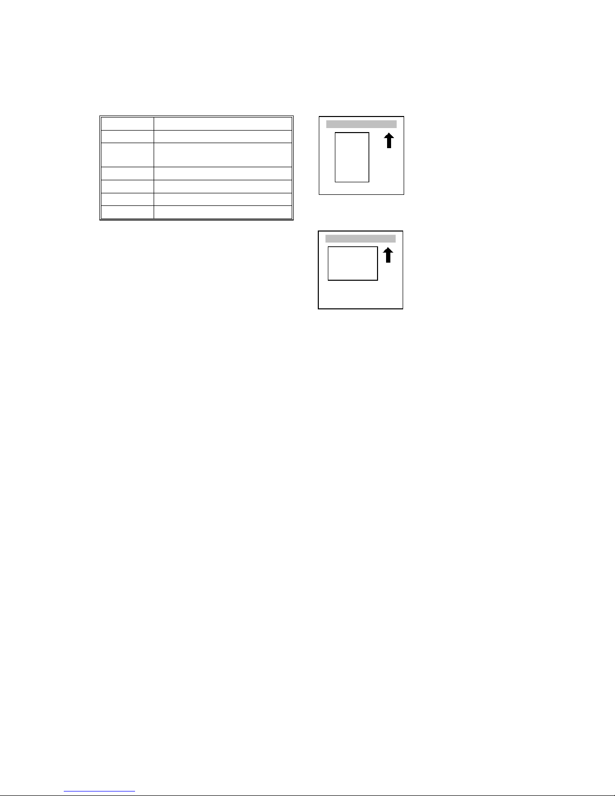
Lengthwise, SEF
(Short Edge Feed)
Sideways, LEF
(Long Edge Feed)


INSTALLATION B010
PREVENTIVE MAINTENANCE B010
REPLACEMENT AND ADJUSTMENT B010
TROUBLESHOOTING B010
SERVICE TABLES B010
DETAILED DESCRIPTIONS B010
SPECIFICATIONS B010
TAB
POSITION 2
TAB
POSITION 1
TAB
POSITION 3
TAB
POSITION 4
TAB
POSITION 6
TAB
POSITION 5
TAB
POSITION 8
TAB
POSITION 7


INSTALLATION


PREPARATION
SM 1-1 B010
Installation
1. INSTALLATION PROCEDURE
1.1 PREPARATION
1.1.1 ENVIRONMENT
1. Temperature Range:
10°C to 32°C (59°F to 86°F)
2. Humidity Range: 15% to 80% RH
3. Ambient Illumination: Less than 1,500 Lux (do not expose to direct
sunlight).
4. Ventilation: Minimum space 20 m3 (approx. 700 cubic ft.)
Room air should turn over at least 3 times per hour.
5. Ambient Dust: Less than 0.075 mg/m
3
6. If the installation location is air-conditioned or heated, place the machine as
follows:
a) Where it will not be subjected to sudden temperature changes from low to
high, or vice versa.
b) Where it will not be directly exposed to cool air from an air conditioner in
the summer.
c) Where it will not be directly exposed to reflected heat from a space heater
in the winter.
7. Avoid placing the machine in an area filled with corrosive gases.
8. Avoid any area higher than 2,000 m (6,500 ft) above sea level.
9. Place the machine on a strong and level base.
10. Avoid any area where the machine may be subjected to frequent strong
vibration.
PREPARATION
B010 1-2 SM
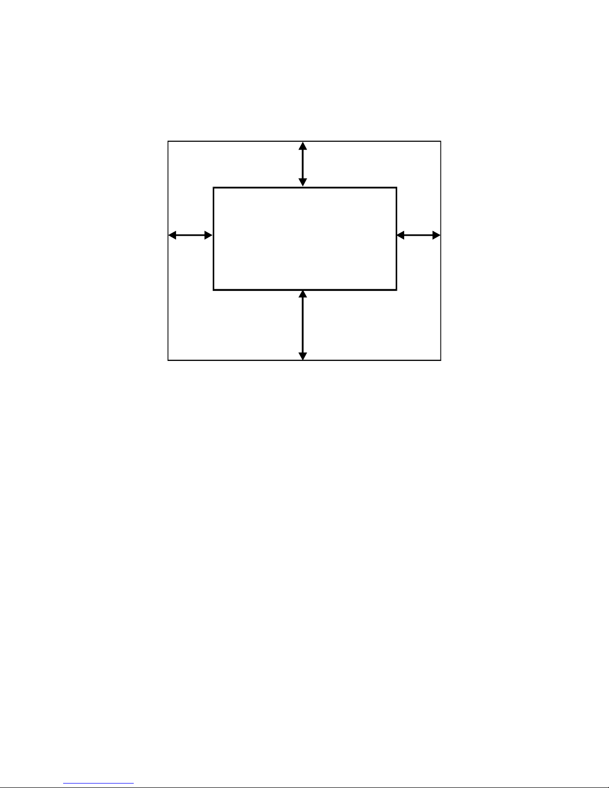
1.1.2 MINIMUM SPACE REQUIREMENTS
1. Front: 1,000 mm (39")
2. Back: 450 mm (18")
3. Right: 450 mm (18")
4. Left: 400 mm (16")
1.1.3 MACHINE LEVEL
1. Front to back: Within 0.15 mm/1000 mm (0.006”/39.4”) of level
2. Right to left: Within 0.15 mm/1000 mm (0.006”/39.4”) of level
Make sure that the machine is level using a carpenter’s level.
B010I520.WMF
Back 450 mm
Right
450 mm
Front 1,000 mm
Left
400 mm

PREPARATION
SM 1-3 B010
Installation
1.1.4 POWER SOURCE
The machine must be installed in a building /facility equipped with a protective
device such as a circuit breaker, as the machine relies on such devices for
protection against over-current and short circuits
1. Input Voltage Level: 120V, 60Hz
More than 20 A (for the U.S.A. version)
220 ~ 240V, 50/60Hz
More than 10 A (for the European version)
2. Permissible Voltage
Fluctuation:
±
10%
3. Do not set anything on the power cord.
NOTE:
1) Make sure the plug is firmly inserted in the outlet.
2) Avoid multi-wiring. A dedicated line is recommended.
4. The recommended wall receptacle follows the NEMA Plug Configuration
indicated below.
NEMA 5-20 R
Standard 20 Amp
120 Volt Receptacle
NEMA 5-20 P
Standard 20 Amp
120 Volt Plug

COPIER INSTALLATION PROCEDURE
B010 1-4 SM
1.2 COPIER INSTALLATION PROCEDURE
1.2.1 ACCESSORY CHECK
Check the accessories and their quantities against the following list:
Description Q’ty
Paper Holder........................................................................... 4
Original Guide Tray................................................................. 1
Original Guide Tray Hinge – Right .......................................... 1
Original Guide Tray Hinge – Left............................................. 1
Upper Original Exit Guide ....................................................... 3
Upper Original Exit Guide Joint (B010-22, -27 only) ............... 2
Rear Original Tray................................................................... 3
Rear Copy Tray Guide - Large................................................ 1
Rear Copy Tray Guide - Small................................................ 1
Rear Copy Tray....................................................................... 3
Rear Copy Tray Holder ........................................................... 3
Cushion - Rear Copy Tray Holder (B010-22, -27 only) ........... 3
Guide Mylar - Small ............................................................... 3
Guide Mylar - Large ................................................................ 1
Front Copy Tray...................................................................... 1
Leveling Shoes ....................................................................... 4
Tapping Screw – M4 x 8 ......................................................... 6
Screw with Washer – M4 x 10................................................. 2
NECR (B010-17, -27 only) ...................................................... 1
Decal - Operation (B010-22, -27 only) .................................... 1
Decal - Paper Tray (B010-22, -27 only) .................................. 1
Decal - Toner Supply (B010-22, -27 only)............................... 1
Copy Instructions Guide (B010-17 only) ................................. 1
System Instructions (B010-17 only) ........................................ 1
 Loading...