

Ricoh AZALEA Service Manual

IMPORTANT SAFETY NOTICES
PREVENTION OF PHYSICAL INJURY
1. Before disassembling or assemb ling part s of th e cop ier an d peripherals,
make sure that the copier po wer cord is unplugg ed .
2. The wall outlet should be near the copie r and easily acce ssible .
3. Note that some comp on en ts of the copie r and the paper tra y unit are
supplied with electrical voltage even if the main switch is turned off.
4. If any adjustment or opera tio n che ck has to be made with exterior covers
off or open while the main switch is turned on, keep hands away from
electrified or mechanically drive n comp on en ts.
5. If the start key is pressed before the copier completes the warm-up period
(Start key starts blinking red an d gre en alte rna tively), keep hands away
from the mechanical and th e ele ctrica l compo ne nt s as the copie r st art s
making copies as soon as the warm-up period is completed.
6. The inside and the meta l parts of the fusing unit beco me ext reme ly hot
while the copier is operat ing . Be careful to avoid touching th ose
components with your bare hands.
HEALTH SAFETY CONDITIONS
1. Never operate th e cop ier with ou t th e ozone filters installed .
2. Always replace the ozo ne filte rs wit h th e spe cifie d on es at the specif ied
intervals.
3. Toner and develope r are no n-t oxic, but if you ge t eit he r of them in your
eyes by accident, it may cause temp ora ry eye discomfort. Try to remove
with eye drops or flush with wat er as first aid. If unsucce ssful, get medical
attention.
OBSERVANCE OF ELECTRICAL SAFETY STANDARDS
1. The copier and its peripherals must be inst alle d and main ta ine d by a
customer service represen ta tive who has comple te d th e training course
on those models.
CAUTION
I
2. The RAM board on the system control board has a lithium battery
which can explode if replace d incor re ctl y. Repla ce the batter y only
with an identical one. The manufacturer recommends replacing the
entire RAM board. Do not recharge or burn this batte ry . Use d
batteries must be handled in accor danc e wi th local regulations.
SAFETY AND ECOLOGICAL NOTES FOR DISPOSAL
1. Do not incinerate the ton er bottle or the used toner. Toner dust may ignite
suddenly when exposed to open flame.
2. Dispose of used toner, developer, and organic photoconductor according
to local regulations. (These are non-to xic supp lies. )
3. Dispose of replaced part s in accord an ce with local reg ula tio ns.
4. When keeping use d lith ium ba tt eries in order to dispose of them later, do
not put more than 100 batteries per sealed box. Storin g larg er numbers or
not sealing them apart may lead to chemical rea ctions and heat build-up.
LASER SAFETY
The Center for Devices and Radiological Health (CDRH) prohibits the repair
of laser-based optical units in the field. The optical housin g unit can only be
repaired in a factory or a t a loca tio n with the requ isite equ ipme nt. The laser
subsystem is replaceable in th e fie ld by a qu alif ied Custo mer En gin ee r. The
laser chassis is not repairable in the fie ld. Customer engineers are th ere fo re
directed to return all chassis and laser subsystems to the factory or service
depot when replacemen t of the opt ical sub syste m is required.
DANGER
I
Use of controls, or adjustment, or perform anc e of proce dure s other
than those specified in this ma nual may result in hazardous radiation
exposure.
WARNING FOR LASER UNIT
I
DANGER: Turn off the main switch before attempting any of the
procedures in the Laser Unit section. Laser beams
can seriously damage your eyes.
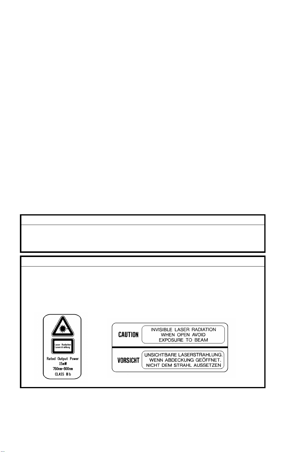
CAUTION MARKING:

SECTION 1
OVERALL
MACHINE INFORMATION
A579
FP Table
10 May 1996 SPECIFICATIONS
1. SPECIFICATIONS
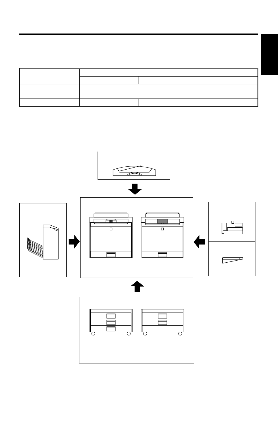
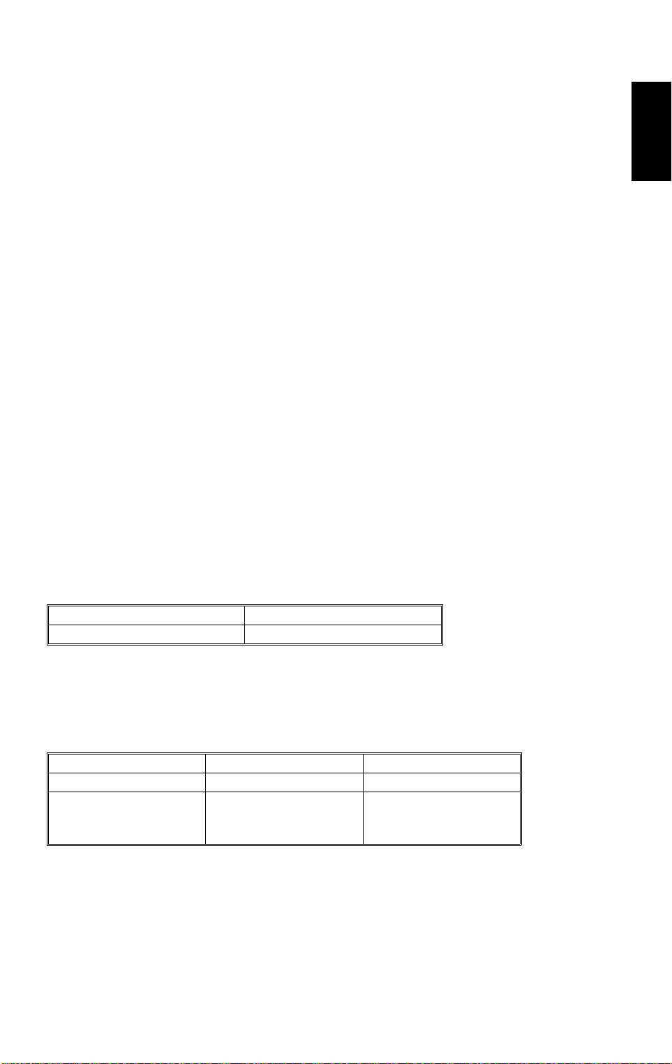
1.1 MACHINE CONFIGURATION
Basic Machine Edit Machine
A166 A187 A189
Operation Panel 20-digit 2-line LCD
Paper Tray Unit 250 Sheets Duplex
ARDF
A548
Copier
Sorter/Stapler
A166/A187 A189
A555
Overall
Information
144 mm x 192 mm
Touch Panel Display
FPU
A718
BASIC
250-sheet Paper
Tray / Duplex Tray
Paper Tray Unit
A549
500 sheets
x 3 Trays
EDIT
Duplex Tray
A550
500 sheets
x 2 Trays
A166V517.wmf
1-1
SPECIFICATIONS 10 May 1996
1.2 GENERAL SPECIFICATI ON S
Configuration: Desk Top
Copy Process: Dry Electrostatic Transfe r Syste m
Resolutions: 400 dpi
Gradations: 256 gradations
Originals: Sheet/Book/Object
Original Size: Maximum 11" x 17" /A3
Copy Paper Size:
Maximum Minimum
Paper Tray Feed 11" x 17" /A3 5
Bypass Feed 11" x 17" /A3 5
1/2 x 81/2 /A5(S)
1/2 x 81/2 /A5(L/S), A6(L)
Copy Paper Weight:
Paper Tray Feed 17 to 24 lbs 64 to 90 g/m
Bypass Feed 14 to 43 lbs 52 to 157 g/m
Auto Duplex
Tray
17 to 28 lbs 64 to 104 g/m
2
2
2
Reproduction Ratios:
81/2" x 11"/11" x 17" version A4/A3 version
Enlargement 121, 129, 155, 200, 400% 115, 122, 141, 200, 400%
Full size 100% 100%
Reduction 25, 50, 65, 74, 77, 85, 93% 25, 50, 65, 71, 75, 82, 93%
Programmable 2 user ratios 2 user ratios
Zoom: From 25% to 400 % in 1% steps.
1-2
10 May 1996 SPECIFICATIONS
Copying Speed:
81/2" x 11" (S) /A4 11" x 17"/A3
Normal Mode
Full Color (4 scans) 3 cpm 1.5 cpm
Single Color (C, M Y, K) 21 cpm 11 cpm
Single Color (R, B) 4 cpm 3 cpm
Single Color (G) 3 cpm 2.5 cpm
OHP/Thick Paper Mode
Full Color (4 scans) 1.5 cpm 1 cpm
Single Color (C, M Y, K) 2.5 cpm 1.5 cpm
Single Color (R, G, B) 2 cpm 1 cpm
First Copy Time:
81/2" x 11" (S) /A4 11" x 17" /A3
Normal Mode
Full Color (4 scans) 32 seconds 52 seconds
Single Color (K) 15 seconds 20 seconds
Single Color (C, M, Y) 20 seconds 20 seconds
Single Color (R, B) 25 seconds 35 seconds
Single Color (G) 30 seconds 40 seconds
OHP/Thick Paper Mode
Full Color (4 scans) 50 seconds 70 seconds
Single Color (K) 35 seconds 45 seconds
Single Color (C, M, Y) 35 seconds 45 seconds
Single Color (R, B) 40 seconds 55 seconds
Single color (G) 45 seconds 60 seconds
Overall
Information
Warm-up Time: Approx. 6 minutes (at 68°F / 20°C)
1-3

SPECIFICATIONS 10 May 1996
Duplexing:
Basic Manual Duplex
Model (A166):
Basic Auto Duplex
Model (A187):
Edit Auto Duplex Model
(A189):
Non-Reproductio n Are a:
Leading Edge:
Side:
Manual Duplexing in full color and Single
Color mode
Manual & Auto Duplexing in Full Color an d
Single Color mode
Manual & Auto Duplexing in Full Color an d
Single Color mode
Duplex can be done on 64-104 g/m2 paper.
Manual Duplexing can be done thro ug h th e
Bypass table only, and th e use r sh ould press
the Duplex Side 2 key before coying the reverse
side.
0.2" ± 0.08" (5 mm ± 2 mm)
0.08" ± 0.08" (2 mm ± 2 mm)/
Total less than 0.16" (4 mm)
Trailing Edge
Front side 2.5 mm ± 2.0 mm
Back side 6.0 ± 2.0 mm
(back side trailing edge is adjustab le by SP
mode from 0.5 to 10 mm)
Copy Number Input: Number keys, 1 to 99
Copy Number Input
(Auto Duplex):
Number keys
Single Color - 1 to 50: smaller than A3, 11" x 17"
1 to 30: A3, 11" x17"
Full Color 1 to 20: all sizes
Image Density: Auto/Manual (7 steps)
Automatic Reset: Yes (10 to 900 seconds or Off )
Paper Capacity: Tra y:
250 sheets x 1 tray
(Basic Manual Duplex Model: A166)
Bypass:
40 sheets Normal paper (80 g/m2)
20 sheets OHP
1 sheet Adhesive paper
1-4

10 May 1996 SPECIFICATIONS
Toner Replenishment: Black:
Toner Addition (300 g/ca rtid ge )
Color (Y, M, C):
Toner Addition (100 g/ca rtrid ge )
Copy Tray Capacity: 100 sheets (11" x 17"/A3 and smaller )
Power Source: 120 V/ 60Hz, 220-2 40 V/ 50,6 0 Hz
Overall
Informati o n
Maximum Power
1.5 kVA
Consumption:
Dimensions (with Platen Cover):
Width Depth Height
Basic Manual Duplex
(A166)
Basic Auto Duplex
(A187)
Edit Auto Duplex
(A189)
620 mm
24.4"
620 mm
24.4"
620 mm
24.4"
700 mm
27.5"
700 mm
27.5"
750 mm
29.5"
632 mm
24.9"
632 mm
24.9"
632 mm
24.9"
Weight: Manual Duplex: 105 kg (231.3 lb)
Auto Duplex: 109 kg (240.1 lb)
Optional Equipmen t: Automatic Document Feeder (ARDF): A548
Sorter Stapler: A555
Film Projector: A718
Holder for Film Projector Unit: A579
Paper Tray Unit (3 Trays & 2 Trays): A549/A550
Key Counter
1-5

SPECIFICATIONS 10 May 1996
1.3 DETECTABLE ORIGINAL SIZE BY PLATEN/ARDF
Size
(width x length)
[mm]
A3 (297 x 420)L No Yes No Yes
B4 (257 x 364)L No Yes No Yes
A4 (210 x 297)L No Yes Yes Yes
A4 (297 x 210)S No Yes Yes Yes
B5 (182 x 257)L No Yes No Yes
B5 (257 x 182)S No Yes No Yes
A5 (148 x 210)L No No* No Yes
A5 (210 x 148)S No Yes No Yes
B6 (128 x 182)L No No No Yes
B6 (182 x 128)S No No No Yes
11" x 17" (DLT) Yes No Yes Yes
11" x 15" No No Yes No
10" x 14" Yes No Yes No
8.5" x 14" (LG) Yes No Yes No
8.5" x 13" (F4) No Yes No Yes
8.25" x 13" No No No No
8" x 13"(F) No No Yes No
8.5" x 11" (LT) Yes No Yes Yes
11" x 8.5" (LT) Yes No Yes Yes
8" x 10.5" No No No No
8" x 10" No No Yes No
5.5" x 8.5" (HLT) No* No Yes No
8.5" x 5.5" (HLT) Yes No Yes No
A6 (105 x 148)L No No No No
Inch version Metric version Inch version Metric version
Platen ARDF
* : For A5 lengthwise/HLT, SP4-303 can be used to select "Can no t de te ct
original size" or "A5 lengthwise/5.5 " x 8.5"(HLT)".
1-6

10 May 1996 SPECIFICATIONS
1.4 COPY PAPER SIZE
Size
(width x length)
[mm]
A3 (297 x 420)L No Yes Yes Yes Yes Yes
B4 (257 x 364)L No Yes Yes Yes Yes Yes
A4 (210 x 297)L Yes Yes Yes Yes Yes Yes
A4 (297 x 210)S Yes Yes Yes Yes Yes Yes
B5 (182 x 257)L No Yes No Yes Yes Yes
B5 (257 x 182)S No Yes No Yes Yes Yes
A5 (148 x 210)L No No No No Yes Yes (1)
A5 (210 x 148)S No Yes Yes Yes Yes Yes (2)
B6 (128 x 182)L No No No No Yes Yes (1)
B6 (182 x 128)S No No No No No No
11" x 17" (DLT) Yes Yes Yes Yes Yes Yes
11" x 15" Yes No Yes No Yes Yes
10" x 14" Yes No Yes No Yes Yes
8.5" x 14" (LG) Yes No Yes No Y es Yes
8.5" x 13" (F4) Yes Yes Yes Yes Yes Y e s
8.25" x 13" No No Yes Yes Yes Yes
8" x 13"(F) No No Yes Yes Yes Yes
8.5" x 11" (LT) Yes Yes Yes Yes Yes Y e s
11" x 8.5" (LT) Yes Yes Yes Ye s Y es Yes
8" x 10.5" No No Yes No Yes Ye s
8" x 10" Yes No Yes Yes Yes Yes
5.5" x 8.5" (HLT) No No No No Yes Yes (1)
8.5" x 5.5" (HLT) Yes No Yes Yes Yes Yes (2)
A6 (105 x 148)L No No No No Yes Yes (2)
Inch
version
Trays in the main body Bypass
Paper Tray Duplex Tray
Metric
version
Inch
version
Metric
version
All
versions
Optional
S.Stapler
Overall
Informati o n
Yes (1): Stapling is not allowed.
Yes (2): Using the Proof Tray only. Sort er bins cannot be used.
1-7

SPECIFICATIONS 10 May 1996
1.5 PAPER SIZES AVAILABLE WITH AP S
– For metric machines –
200
173
163
141
122
115
100
93
87
82
75
71
65
61
57
50
~
~
~
~
~
~
~
~
~
~
~
~
~
~
~
~
174
164
142
123
116
101
94
88
83
76
72
66
62
58
51
A3 – – – – – – A3 – B4 – – A4L 8.5
B4 –––––A3B4––A4L8.5
A4L – – – A3 B4 – A4L 8.5
B5L ––A3B4–A4LB5L––A5L––––––
A5L A3B4–A4LB5L–A5L–––––––––
A4S ––––––A4S–B5S––A5S––––
B5S –––––A4SB5S––A5S––––––
A5S –––A4SB5S–A5S–––––––––
8.5
x 11
x 8.5
8.5
x 13
x 15
––––––8.5
x11
11
––––––11x
8.5
––––A3–8.5
x 13
11
––––––11x15–––––––––
B5L – – A5L – – – –
x 13
–––––––––
–––––––––
––A4LB5L––––A5L
B5L – – A5L –
x 13
B5L – A5L
x 13
: Not allowed in platen cover mode. L: Len gt hwise S: Sidewa ys
– For inch machines –
200
176
155
129
121
100
93
85
77
74
65
~
~
~
~
~
~
~
~
~
~
~
177
156
130
122
101
94
86
78
75
66
51
11x17 – – – – – 11x17 11x17 11x15 8.5
x14
11x15 – – – – – 11x15 11x15 – 8.5
x14
8.5x14 ––––11
8.5x11 –– 11x17–8.5
5.5x8.5 11
x1711x15
8.5x5.5 –––11
11x8.5 –––––11
8x10 – – – 11x17 10x14 8x10 – – – – 5.5
10x14 – – – – – 10x14 – 8.5
8x13 – – – 11x17 – 8x13 – – – – 5.5
8.5
x14
8.5
x11
x8.5
8.5
x17
x14
x11
–5.5
x8.5
–8.5
x5.5
x8.5
––8.5
x11
––––5.5
––––––
––––––
––––8.5
8.5
x14
x11
–8.5
x11
8.5x11 – 5.5
––5.5
x8.5
x5.5
x8.5
––5.5
x8.5
50
~
5.5
x8.5
x8.5
x8.5
–
–
–
x14
–
: Not allowed in platen cover mode.
1-8
10 May 1996 SPECIFICATIONS
NOTE: 1) The tables show which copy paper size is select ed for each
original size for zoom ratios from 50 to 200 %.
2) When a zoom ratio is specified, APS automatically selects a
paper size that can guarantee the quality of the magnifie d cop y
image if there is a paper size available fo r the equivale nt standard
reproduction ratio.
3) If paper of the detect ed size has run out , th e mach ine displays
the message "Set xx M paper in tray" and stops the job (copyin g
is enabled ) .
4) For "–" in the above tables, the machin e disp lays the message
"Cannot detect orig inal size" and stops the job (copying is
enabled). The selected paper feed tray does not change.
5) When 49% or less or 201% or more is selected, APS works in
the same way as described in Note 4 ab ove .
6) APS also supports the by-pass feed table (excep t fo r
non-standard paper sizes). When a sele cte d pa per size can on ly
be fed from the by-pass fee d ta ble, the machine displays a
warning to instruct the user to use the by-pass fee d ta ble .
7) APS does not support A6 and B6 sizes.
Overall
Informati o n
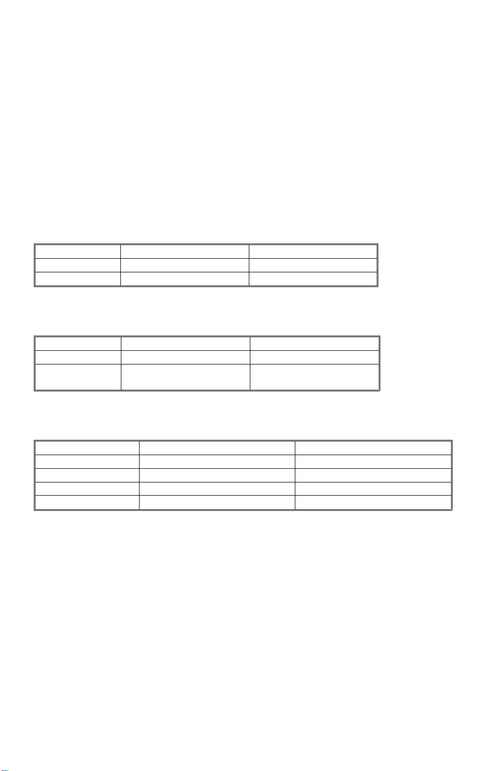
1.6 NOISE EMISSION
Sound pressure level (The measurements are made in accordance with ISO
7779 at the operator positions.)
Copier only Full system*
Less than 61 dB (A) Less than 65 dB (A)
* Full system: Copier with documen t fe ed er, 500 shee ts x 3 trays unit, FPU,
and a sorter stapler.
Sound power level (The measurements are made in accordance with ISO
7779.)
Copier only Full system*
Stand-by Less than 54 dB (A) Less than 58 dB (A)
Copying
(This value is for the
black copy mode.)
* Full system: Copier with documen t fe ed er, 500 shee ts x 3 trays unit, FPU,
and a sorter stapler.
Less than 67 dB (A) Less than 71 dB (A)
1-9
SPECIFICATIONS 10 May 1996
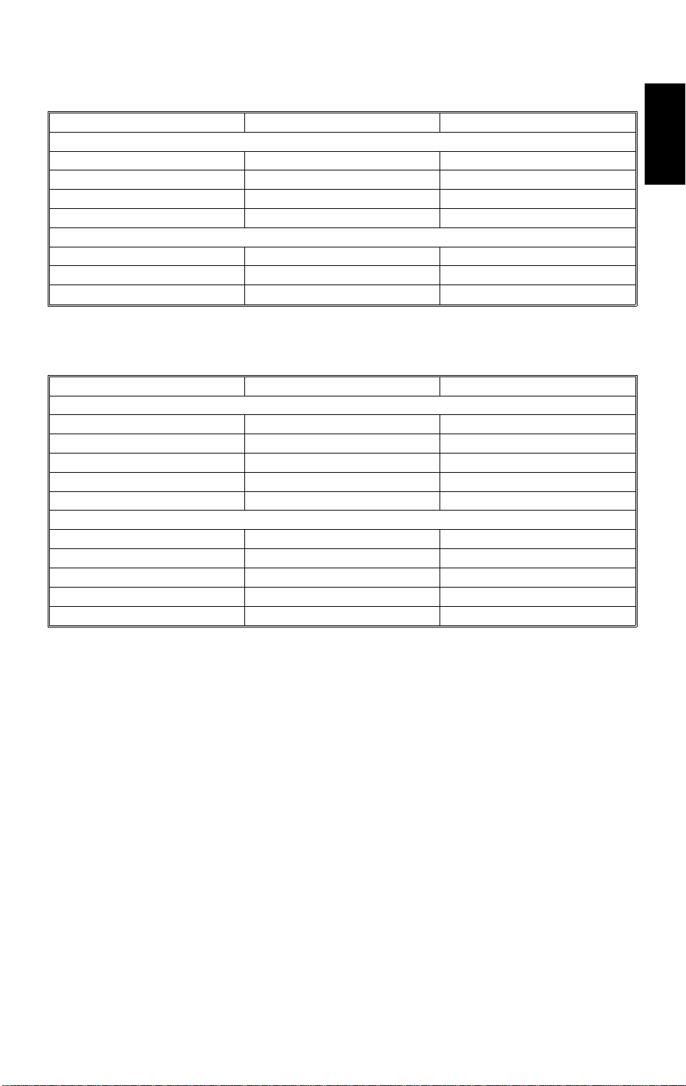
1.7 POWER CONSUMPTION
(1) Maximum power consumption
1.5 kVA
(2) Average power consumption
A189 Copier
Standby 0.25 kW 0.5 kW
Warm-up 1.25 kW 1.25 kW
Copying 1.15 kW 1.15 kW
Energy Saver
Mode
Value for standby
minus 7 W
A189 Copier +
DJF + Sorter
Value for standby
minus 7 W
NOTE: 1) Copying was done in the 1C (A3) repea t mod e.
2) The power consumption in en erg y saver mod e was mea sure d with
the fusing lamp off.
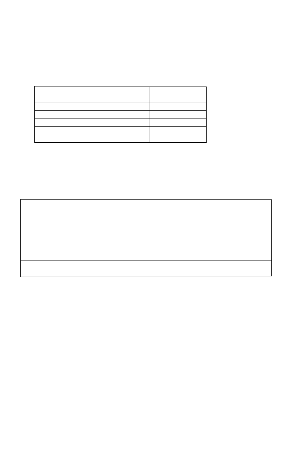
1.8 DISPLAY EDITOR SPECI FI CATI O N
Scanned image • The copier’s scanner scans the image.
• Maximum A3/DLT (11" x 17"): Reduced image display
Displayed image • 144 x 192 mm, 16-gradation (4 bit/dot) monochrome
• 640 x 480 dots, 0.33 mm/dot
• Reduces the dpi of scanned images to approximately 33 dpi and
displays the entire image.
• Zoom display: 3 levels (50 dpi, 67 dpi, 100 dpi)
• Display processing time: 2 seconds or less
Area specification
procedure
• Move the arrow in the screen by using the cursor key and enter a
point by pressing the coordinate entry key.
1-10
10
10 May 1996 MACHINE CONFIGURATION
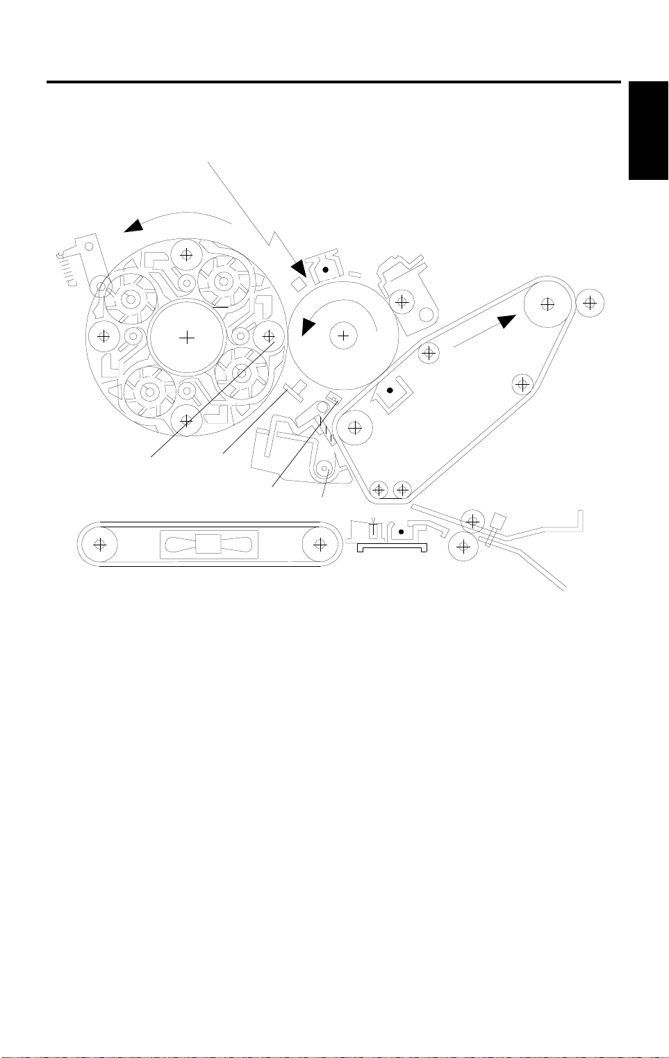
2. MACHINE CONFIGURATION
2.1 COPY PROCESSES AROUND THE DRUM AND BELT
2
1
11
3
7
4
5
6
9
13
Overall
Informati o n
8
12
1. Drum Charge
A166V516.wmf
In the dark, the charge coro na unit gives a nega tive charge to the organic
photoconductive (OP C) drum. The grid plate ensures that corona charg e
is applied uniformly. The charge remain s on the surf ace of the dru m
because the OPC layer has a high elect rical resist ance in th e dark. The
amount of negative charge on the dru m is proportional to the negative
voltage applied to the drum charge corona wire and casin g.
2. Laser Exposure
A laser beam is reflected onto the drum by the polygon and drum mirrors.
This forms an electrical latent image on the drum surface. The amo unt of
charge remaining as a late nt image on the drum depen ds on the laser
beam intensity.
3. Drum Potential Detection
The drum potential sensor detects the streng th of the ele ctric fie ld on the
charged drum. The senso r out pu t is one of th e sign als use d in process
control.
1-11

MACHINE CONFIGURATION 10 May 1996
4. Development
The negatively charged tone r is attra cte d to the latent image on the dru m
surface. Toner particles are electrostatically attracted to the area of the
drum surface where th e lase r redu ced the negat ive charge on the drum.
The development unit is a revolve r-typ e, cont ain ing sepa rat e
development sections for each color toner.
5. Image Density Detection
When the laser forms a sensor pa ttern on the drum surfa ce, the ID
sensor measures the image density of the se patterns. The output signal
is used in process control to regulate toner supply.
6. Pre-transfer Lamp
After development, the pre-transfer lamp reduces the potential of the
image background, right before the first belt tra nsf er (in 2C/ 3C/ 4C mod e).
This ensures that electrosta tic at tra ctio n be twe en belt and drum is about
the same for each color ton er tra nsfer, which ensures that th e colo r t on er
images are synchronized pro perly.
7. Belt Transfer
Toner on the drum is attracted to th e tra nsfer belt by the belt corona unit .
8. Belt Lubrication
The transfer belt lubricant brush applies a small amoun t of lubrica nt to the
surface of the transf er be lt. This aids the belt cleaning blade in re movin g
waste toner from the transfer belt.
9. Belt Cleaning
The cleaning blade removes an y toner on the belt aft er pape r tran sfer.
10. Drum Cleaning
The drum cleaning brush rolle r remove s remain ing ton er fro m the drum.
The cleaning brush also applies lubricant. This aids in drum cleaning.
11. Quenching
The light from the quenchin g lamp elect rically neutralizes the charge on
the drum surface. This prepares the drum for the next copy cycle.
12. Paper Transfer
When all toner has been transferred from the drum to the transfer belt,
the charged tone r on th e tra nsf er be lt is attracted to the paper by the
paper transfer unit . This cha rge is applie d to the underside of the pap er.
13. Paper Separ ati on
The copy paper separates from the tran sfe r belt due to the belt’s
curvature. This curvature allows the paper to natu rally fall away from the
transfer belt. The discharg e bru sh aid s in the separation process by
discharging any remainin g ele ctric cha rge from th e pa per.
1-12
10 May 1996 MAJOR UNIT OVERVIEW
3. MAJOR UNIT OVERVIEW
1
10
Overall
Information
2
3
9
4
8
5, 6
7
A166V506.wmf
1-13

MAJOR UNIT OVERVIEW 10 May 1996
1. Copier
1. Dimensions (W x D x H):
Basic machine - 620 x 700 x 632 mm (with paper tray unit: 620 x 700 x
1010)
Edit machine - 620 x 750 x 632 mm (with paper tra y unit : 620 x 750 x
1010)
2. The printer unit, system con tro l unit , an d scan ner u nit are ind epen dent
modules connected with an interface.
2. Scanner Unit
1. 400 dpi (8 bits/dot) scan nin g in bo th main an d sub scan directions
2. 3-line CCD with reduction optics
3. Exposure lamp: Haloge n lamp
4. 5-phase stepper motor drive
3. Drum Unit
1. The drum unit contains the phot oco nd uct or dru m, cha rge coron a un it,
and cleaning unit
2. Charge corona unit: Sing le scorotron charge
3. Quenching Lamp: Red LEDs
4. Drive: Synchronized with th e transfer belt (dc brushless moto r +
flywheel); full speed = 105 mm/s
5. Potential sen sor and ID sensor included
4. Fusing and Paper Exit Section
1. Fusing: Silicone roller fusin g (bo th hot and pressu re rolle rs)
2. Oil application method: Double rolle r
3. Cleaning: Roller cleaning for the hot roller
Cleaning blade for the pressure roller
4. OHP/Thick paper mode: Half spe ed (52. 5 mm/s)
5. Development and Toner Supply
1. Development: Two-comp on en t mag netic bru sh de velo pme nt
2. Development switching : Revolver System
3. Image density control: ID sensor + Pot entia l senso r (Proce ss cont rol)
4. Toner supply
Black: Screw-in bottle (300 g)
Color: Sector cartridg e (100 g)
5. Toner supply unit: Front of develo pment unit (rotation typ e)
1-14

10 May 1996 MAJOR UNIT OVERVIEW
6. Toner and Developer
1. Color toner: Type E
2. Black toner: Type E
3. Developer: Type F
7. Paper Feed and Transport
1. Paper Tray Unit (A166 copier only)
• Corner Separation System
• Front loading tray (250 sheets) + By-pass table
2. Transport: Transport belt with fan
3. Duplex unit (A187, A189 copier only)
• Duplex unit + By-pass table
4. Paper Tray Unit (option): • 500 sheets x 3 trays (FRR Feed System)
• 500 sheets x 2 trays (FRR Feed System)
8. Transfer and Belt Driv e
1. Transfer belt: Full time cont act with th e dru m
2. Belt transfer: Sing le coro na charg e
3. Paper transfer: Single corona charge
4. Registration: Synchronization by the transfer belt H.P. sensor
5. Drive: Synchronized with th e drum (same motor)
6. Separation: Curva ture separation + discha rge brush
7. Transfer cycle: 1 belt rotation/A4
8. Belt cleaning: Coun te r blade
9. Lubrication: Brush roller with lubrica nt bar
Overall
Informati o n
9. Printer Unit
1. Optics: 6-sided polygon mirror + 2 fθ lenses + BTL
2. Polygon motor (16535 rpm), with ball bearing
3. Resolution: 400 dp i
4. Modulation: PM + PWM
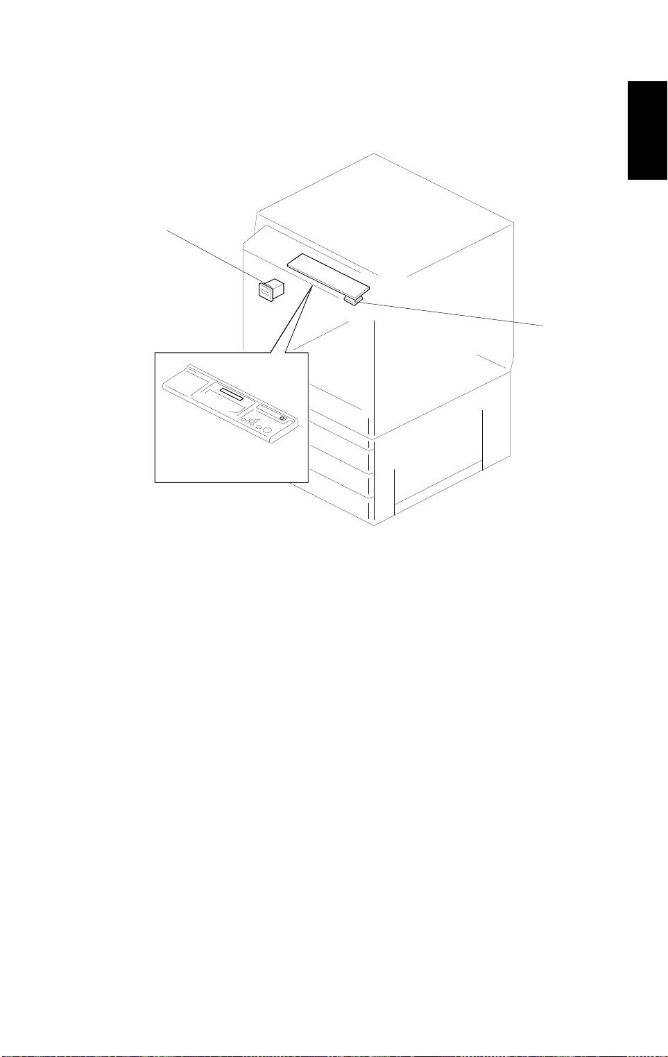
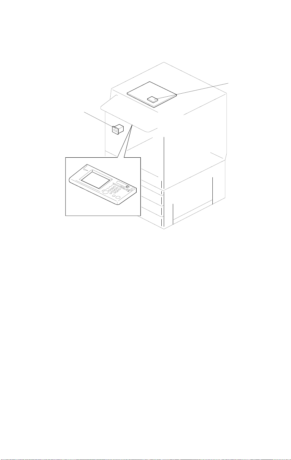
10. System Control Unit (SCU)
1. Basic machine: The SCU is on th e ba ck side of the operation panel
(20-digit 2-line LCD)
2. Edit machine: The SCU is under t he sca nner un it an d con ne cte d to the
touch panel display (640 x 480 dots).
1-15
PARTS LAYOUT 10 May 1996
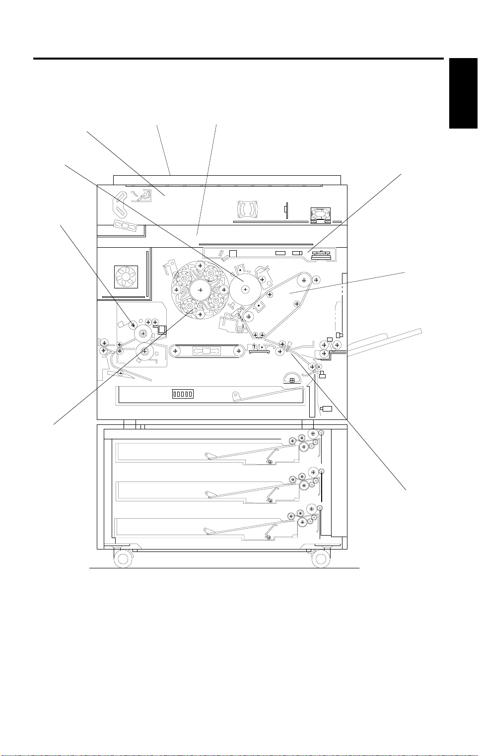
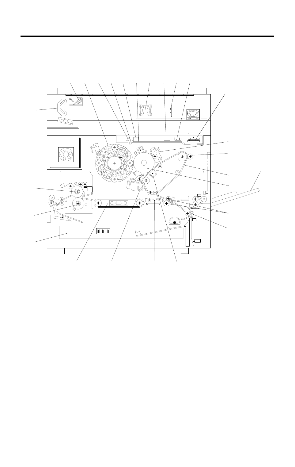
4. PARTS LAYOUT
4.1 MECHANICAL COMPONENT LAYOUT
5 6
4
3
2
1
7
1098
11
1312
14
15
16
17
19
20
21
22
18
26
1. Paper Tray (A166)
Duplex Tray
(A187/189)
2. Pressure Roller
3. Hot Roller
4. 2nd Scann er
5. 1st Scanner
6. Development Unit
7. Drum Mirror
8. Toner Shield Glass
9. BTL
25
10. Charge Corona Unit
11. Lens
12. 2nd fθ Le ns
13. CCD Board
14. 1st fθ Lens
15. Polygon Mirror
16. Drum Cleaning Unit
17. Lubricant Brush
18. By-pass Feed Table
19. Transfer Belt
24
23
A166V500.wmf
20. OPC Drum
21. Registration Rollers
22. Relay Roller
23. Belt Transfer
Charge Unit
24. Paper Transfer
Charge Unit
25. Belt Cleaning Unit
26. Transport Belt
1-16
15
10 May 1996 PARTS LAYOUT
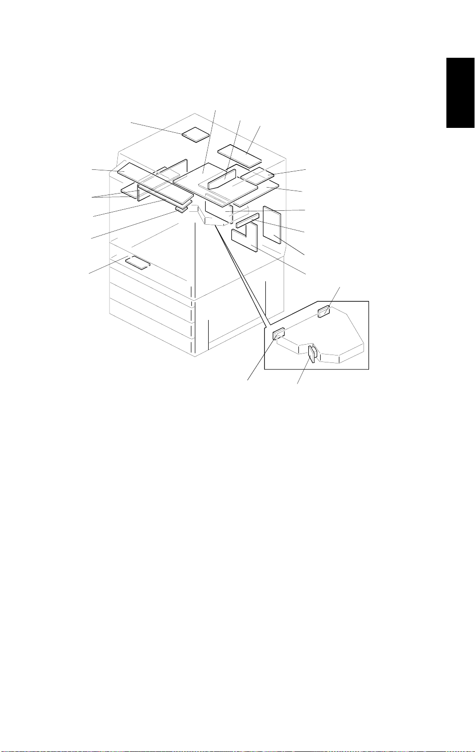
4.2 PCB (A166/A187 COPIERS)
4
3
2
1
18
6
7
5
8
Overall
Information
9
10
11
12
13
14
16
17
A166V507.wmf
1. RAM Board
2 . SCU Board
3. AC Drive/DC Power
Supply Board
4. Operation Panel
5. Scanner Motor Drive
Board
6. Scanner IPU Board
7. CCD Board
8. Lamp Regulator
9. IDU Board
10. Main Control Board
11. I/O Control Board 2
12. By-pass Paper Width
Detection Board
13. I/O Control Board 1
14. High Voltage Supply
Board
15. Laser Synchronizing
Detector Board 2
16. Laser Synchronizing
Detector Board 1
17. LD Drive Board
18. Duplex Control Board
(Except A166)
1-17
PARTS LAYOUT 10 May 1996
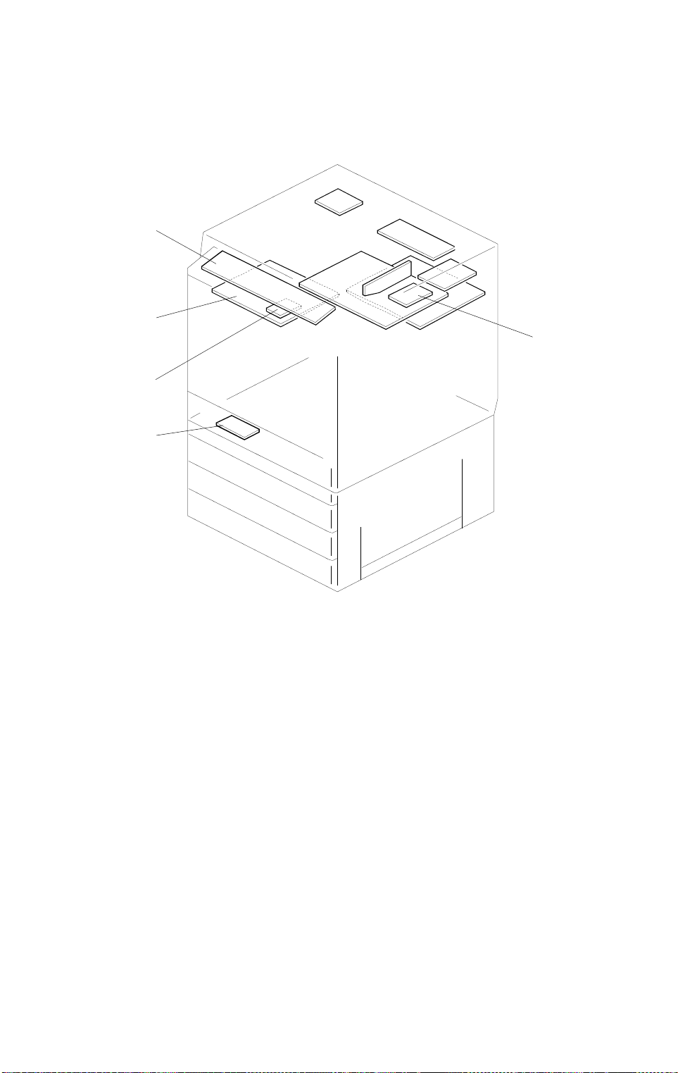
4.3 PCB (A189 COPIER)
20
19
21
23
22
19. SCU Board
20. Operation Panel
21. Extended IPU Board
22. Duplex Control Board
23. RAM Board
A166V508.wmf
1-18

9
765
10 May 1996 PARTS LAYOUT
4.4 SOLENOIDS AND CLUTCHES
3
4
Overall
Informati o n
2
8
1
10
1. Transfer Belt Cleaning SOL
2. Toner Supply Release SOL
3. Junction Gate SOL
(A187/A189 only)
4. Sub By-pass Feed Pick-up
SOL
5. Transfer Belt Lubricant SOL
A166V509.wmf
6. Registration CL
7. Main By-pass Feed Pick-up
SOL
8. By-pass Feed CL
9. Paper Feed CL (A166 only)
10. Vertical Transport CL
1-19
13
PARTS LAYOUT 10 May 1996
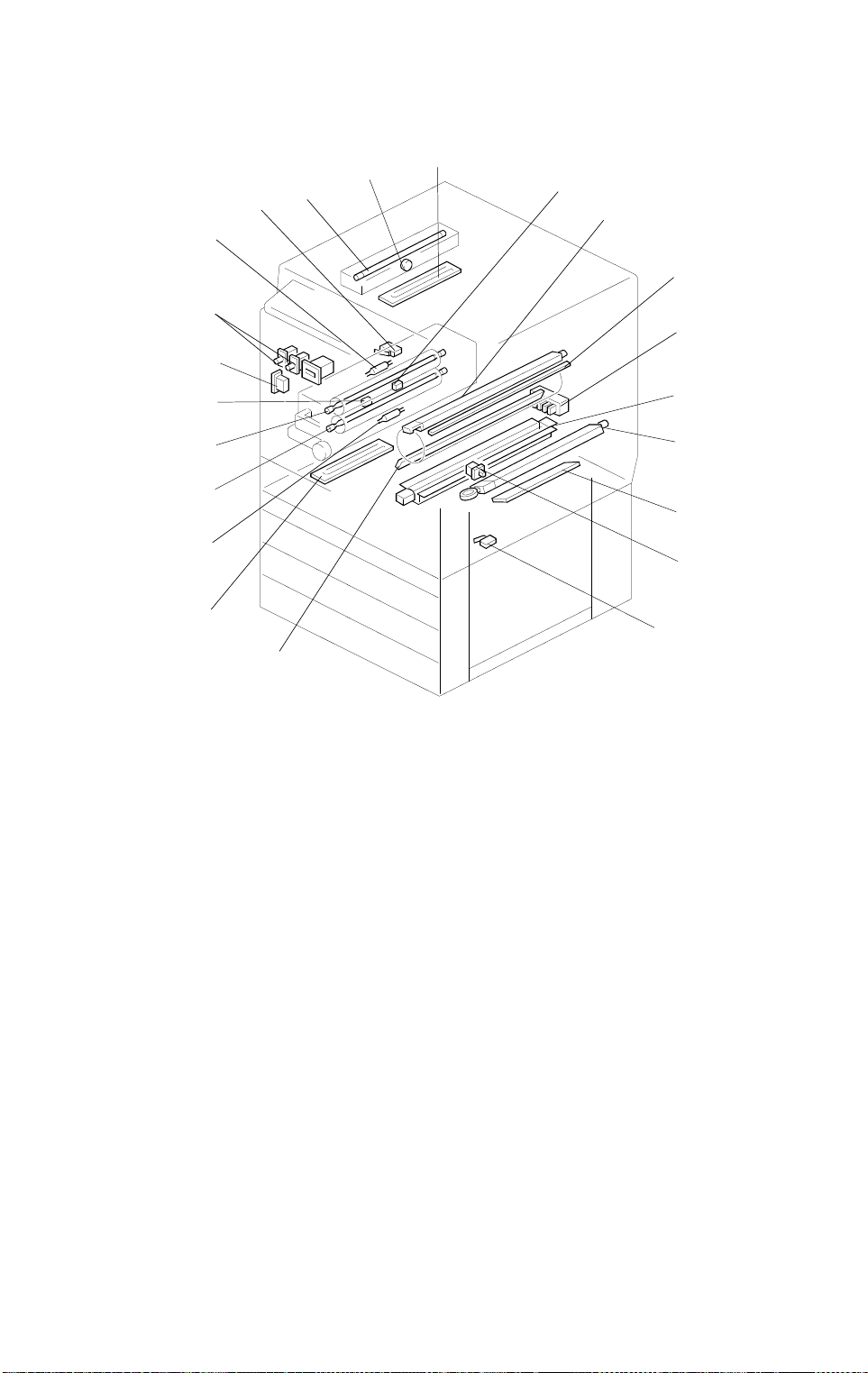
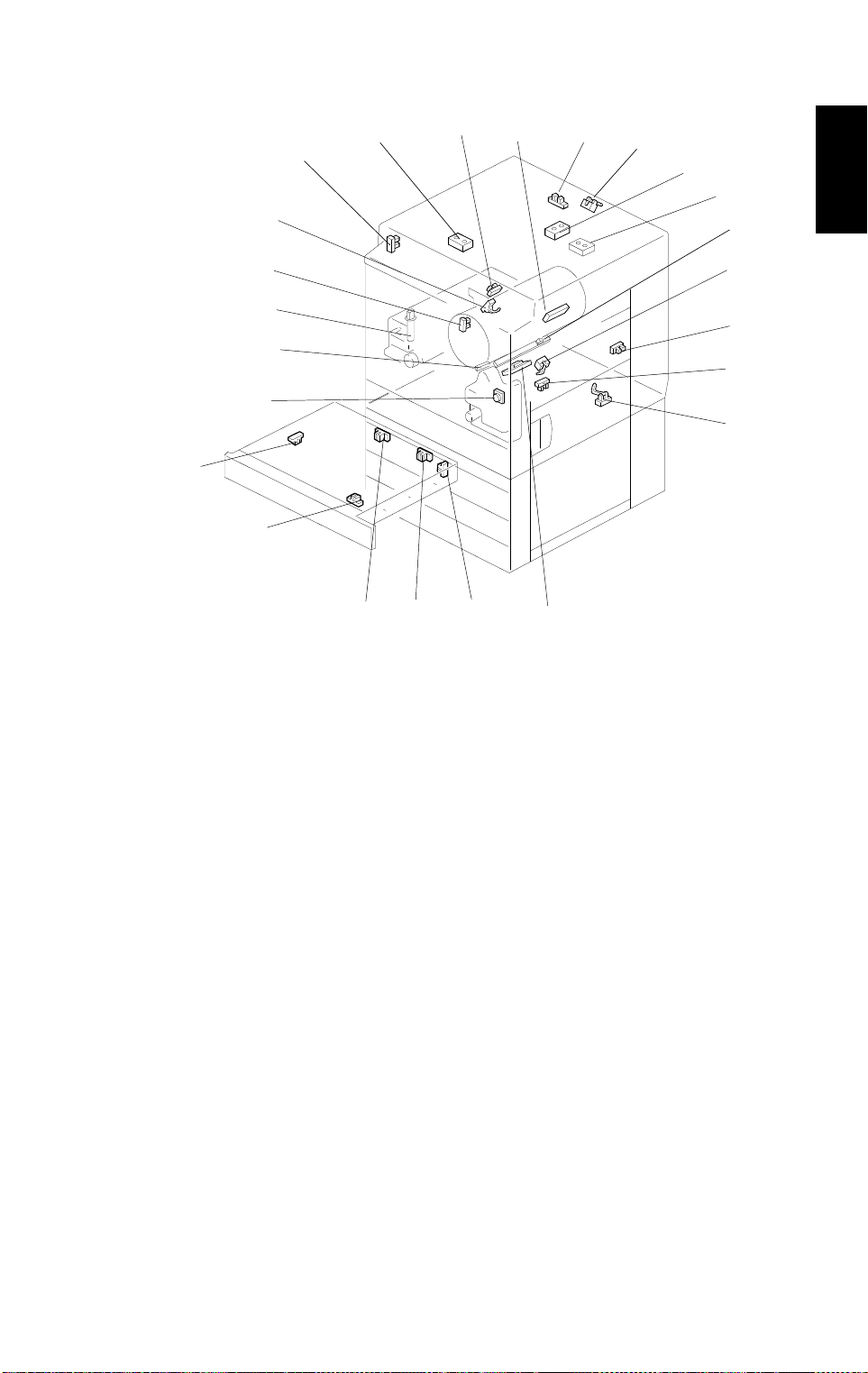
4.5 SWITCHES AND HEATERS
11
10
9
8
7
6
12
14
15
16
5
4
3
2
1
22
1. Lower Tray Heater
2. Pressure Roller Thermofuse
3. Pressure Roller Lamp
4. Fusing Lamp
5. Pressure Roller Thermistor
6. Main Switch
17
18
19
20
21
A166V510.wmf
12. Optics Anticondensat ion
Heater
13. Fusing Thermistor
14. Charge Corona Unit
15. Quenching La mp
16. Tray Paper Size SW
(A166 only)
7. Front Door Switch
8. Fusing Thermofuse
9. Paper Exit Door Switch
(A187/A189 only)
10. Exposure La mp
11. Thermostat
17. Paper Transfer Charge Unit
18. Belt Transfer Charge Unit
19. Drum Heater
20. By-pass Feed Table SW
21. Vertical Transport SW
22. Pre-transfer Lamp
1-20
11
19
10 May 1996 PARTS LAYOUT
4.6 SENSORS
24
1. Used Toner Sensor
23
7
8
6
5
4
9
10
12
13
14
Overall
Information
15
3
16
2
17
1
18
A166V504.wmf
22
21
20
15. Registration Sensor
2. Color Toner Cartridge
Sensor
3 . Oil End Sensor
4. Revolver H.P. Sensor
5. Bk Toner Cartridge Sensor
6. Scanner H.P. Sensor
7. Original Width Sensor
8. Paper Exit Sensor
9. Drum Potential Sensor
10. Platen Cover Position
Sensor
11. Scanner Unit Lift Sensor
12. Original Length Sensor 1
13. Original Length Sensor 2
16. Tray Paper End Sensor
(A166 only)
17. By-pass Feed Paper End
Sensor
18. Vertical Transport Se nso r
19. Transfer Belt H.P. Sensor
20. Duplex Paper En d Sensor
(A187/A189 only)
21. Duplex Turn Sensor
(A187/A189 only)
22. Duplex Entrance Sensor
(A187/A189 only)
23. Side Fence Jogger HP
Sensor (A187/A189 only)
24. End Fence Jogger HP
Sensor (A187/A189 only)
14. ID Sensor
1-21
7
6
PARTS LAYOUT 10 May 1996
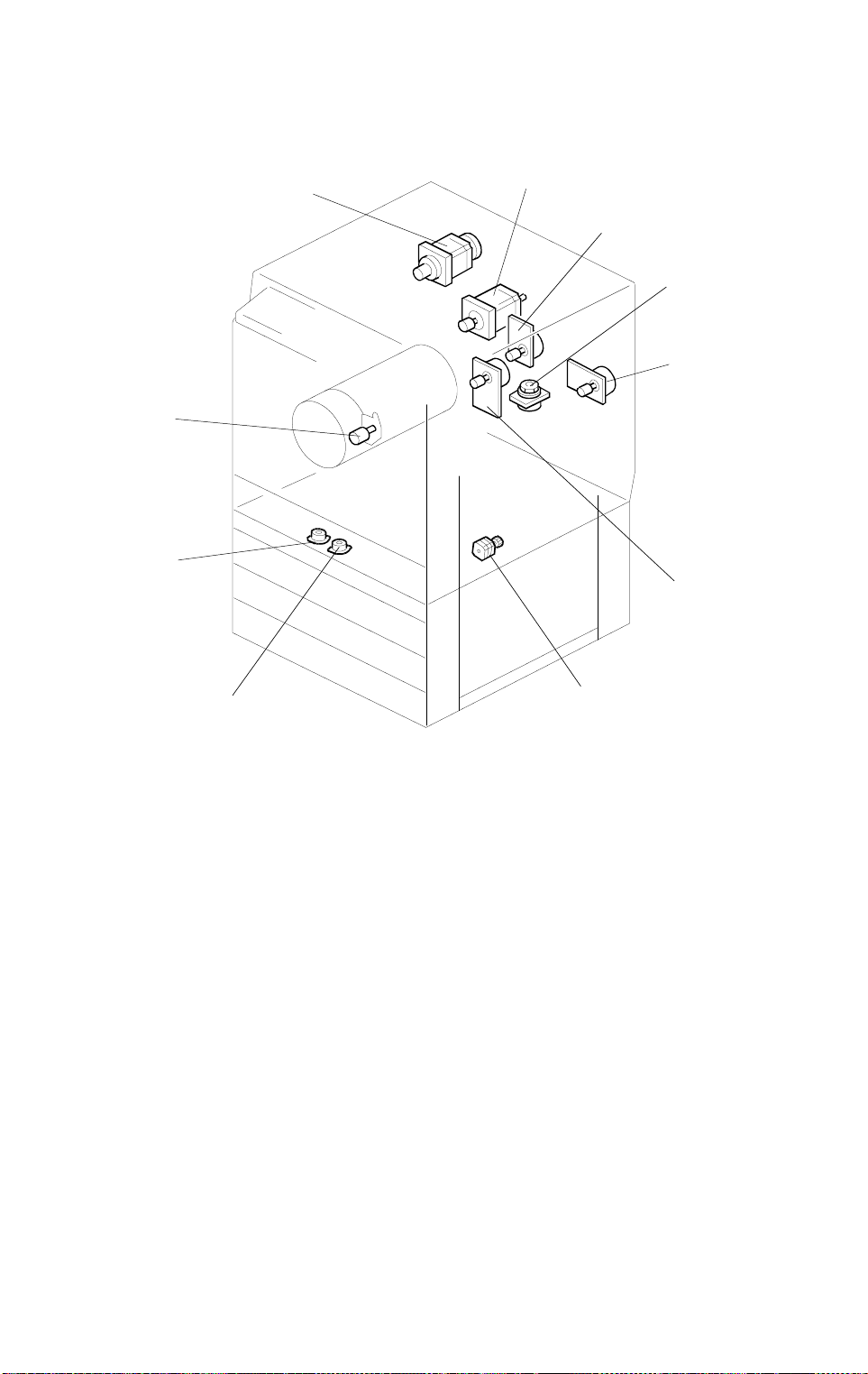
4.7 MOTORS
10
2
3
4
5
1
9
1. Toner Supply Motor
2. Scanner Motor
3. Revolver Drive Motor
4. Development Drive Motor
5. Polygon Motor
6. Drum Motor
8
A166V511.wmf
7. Main Motor
8. Duplex Feed Motor
(A187/A189 only)
9. Side Fence Jogger Motor
(A187/A189 only)
10. End Fence Jogger Motor
(A187/A189 only)
1-22
11109
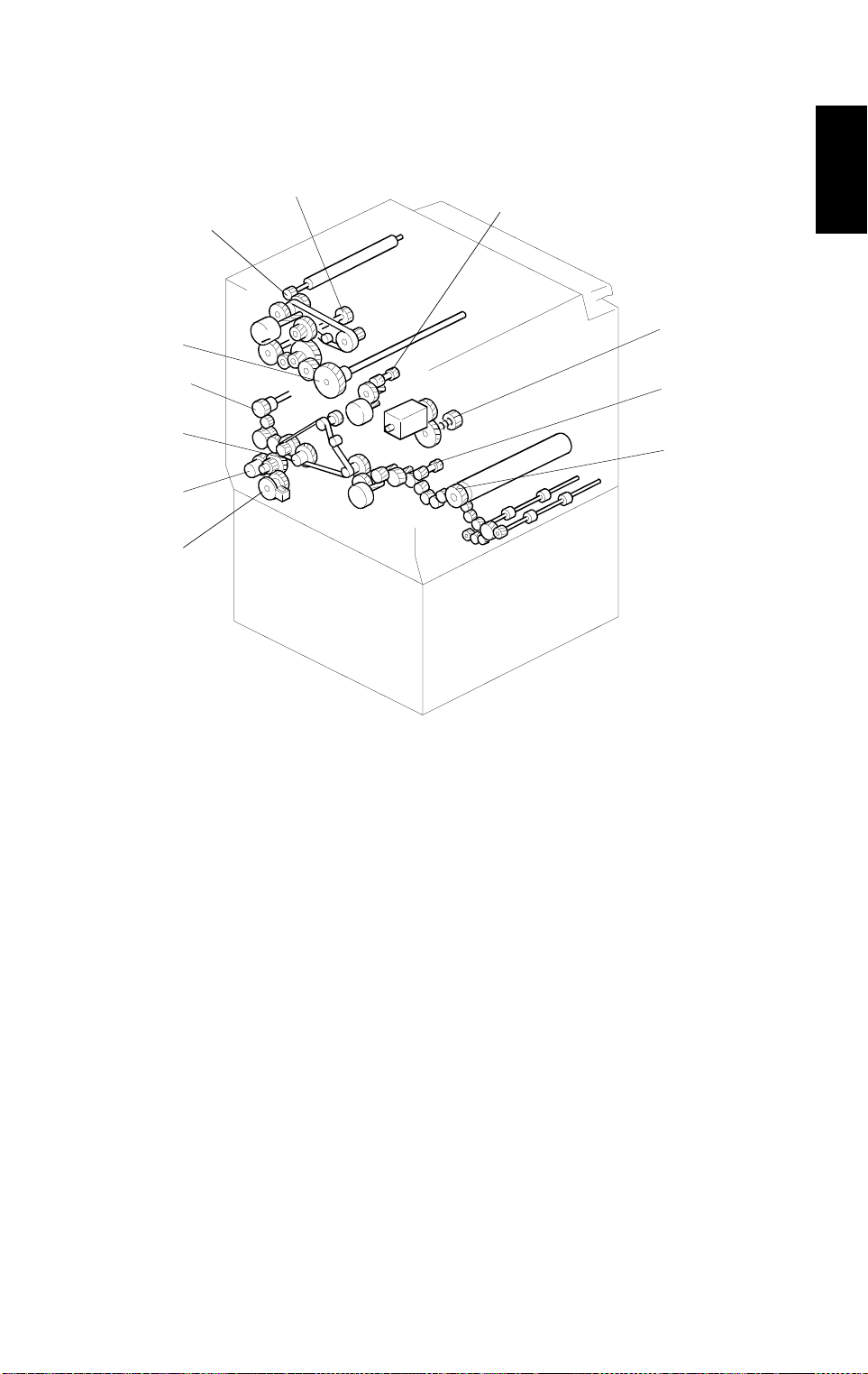
10 May 1996 PARTS LAYOUT
4.8 DRIVE LAYOUT
7
8
6
Overall
Informati o n
5
4
3
2
1
1. Paper Feed Clutch
2. Vertical Transport Clutch
3. Registration Clutch
4. By-pass Feed Clutch
5. Drum Drive Gear
6. Transfer Belt Lubricant
Gear
A166V512.wmf
7. Transfer Belt Drive Gear
8. Development Drive Gear
9. Revolver Drive Gear
10. Transport Unit Drive Gear
11. Fusing Unit Drive Gear
1-23
15
PARTS LAYOUT 10 May 1996
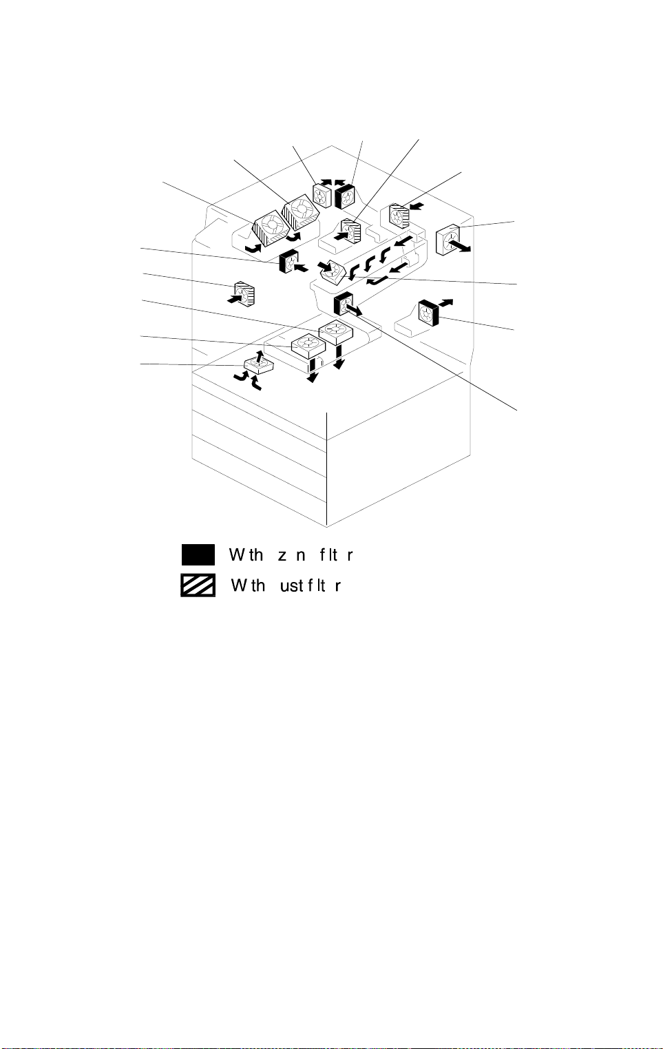
4.9 FANS AND AIR FLOW
8
9
10
7
11
6
12
5
4
13
3
2
14
1
1. Development Inlet Fan
2. Transport Fan 1
3. Transport Fan 2
4. Front Power Supply
Board Fan
5. Paper Exit Fan
6. Optics Cooling Fan 1
7. Optics Cooling Fan 2
8. Rear Power Supply Board
Fan
A166V513.wmf
9. Exhaust Fan
10. Fusing Fan
11. Charge Inlet Fan
12. Optics Exhaust Fan
13. Scanner Board Cooling
Fan
14. Rear Transfer Fan
15. Front Transfer Fan
1-24
10 May 1996 PARTS LAYOUT
4.10 COUNTERS (A166/A187 COP IERS )
1
2
Overall
Informati o n
A166V515.wmf
1. Main Counter
2. Back-up Counter (stored in the RAM board on the SCU board )
1-25
PARTS LAYOUT 10 May 1996
4.11 COUNTER (A189 COPIER)
2
1
A166V514.wmf
1. Main Counter
2. Back-up Counter (stored in the RAM board on the SCU board )
1-26

10 May 1996 ELECTRICAL COMPONENT LIST
5. ELECTRICAL COMPONENT LIST
5.1 PRINTED CIRCUIT BOARDS
Symbol Name Function Remarks
PCB1 Lamp regulator Supplies dc power for the exposure lamp.
PCB2
PCB3
PCB4
PCB5
PCB6 Main control board Controls the printer sequence.
PCB7
PCB8
PCB9 LD drive board Controls the LD output.
PCB10
PCB11
PCB12 IDU board Discriminates image for anti-counterfeiting
PCB13
PCB14
PCB15
PCB16 RAM board Stores the copy process data and counters.
PCB17 Operation panel Used to operate the copier.
PCB18
PCB19
Scanner motor drive
board
CCD board Converts the light reflected from the original
AC drive/
DC power suppy
Scanner IPU board Converts the RGB image signal from the
I/O control board 1 Interfaces the sensors, clutches, solenoids
I/O control board 2 Interfaces the sensors, clutches, solenoids
Laser synchronizing
detector board 1
Laser synchronizing
detector board 2
By-pass paper width
detection board
High voltage supply
board
System control unit
(SCU) board
Extended IPU board Converts scanned image data and sends it
Duplex control board Controls the duplex unit. A187/A189
Supplies dc power for the scanner motor.
into signals.
Supplies ac and dc power.
CCD to a KCMY signal and sends it to the
printer and SCU.
and motors in the printer module with the
main control board. Includes temperature
and humidity sensors.
and motors in the printer module with the
main control board.
Detects laser main scan synchronization
while writing the latent image to the drum.
Detects laser main scan synchronization
while writing the latent image to the drum.
Detects the paper width in the by-pass feed
table.
Supplies power to the corona units.
Controls the system.
to SCU for the display. Performs image
processing on an area specified in the
display.
A189
copier
only
copiers
only
Overall
Information
1-27
 Loading...