

Page 1
G060/G082
PARTS CATALOG
RICOH GROUP COMPANIES
001160MIU
Page 2

Page 3

PARTS CATALOG
G060/G082
RICOH GROUP COMPANIES
Page 4

Page 5

G060/G082
PARTS CATALOG
001160MIU
Page 6

Page 7
LEGEND
PRODUCT CODE COMPANY
GESTETNER LANIER RICOH SAVIN
G060 DSc38 2138 AH AP3800 SLP38c
G082 DSc38F 2138E AP3850C SLP38cDE
G571 Duplex Unit Type 3800C
G567 Paper Feed Unit Type 3800C (1 Tray)
G568 Paper Feed Unit Type 3800C (2 Tray)
G569 Paper Bank PS470
G565 Finisher SR770
B377 Punch Kit Type 1045
G566 Mail Bin Type 3800C
G570
G306 Multi-Bin Unit PT460
G329 Platen Cover Type 3800C
G564 Auto Reverse Document Feeder
G307/G324/G325 Fax Option/G3 Interface Unit Type 3800C/ISDN Option Type 3800C
DSc38S 2138CMF Aficio AP3800CMF SLP38cS
Copier Feature Expander Type 3800C
DOCUMENTATION HISTORY
REV. NO. DATE COMMENTS
* 9/2001 Original Printing
1 2/2002 G570 Addition
2 6/2002 G082 Addition
Page 8

Page 9

G060/G082 PARTS CATALOG
(
TABLE OF CONTENTS
G060 PARTS LOCATION AND LIST
LOCATION AND LIST ............................................. 2
1.EXTERIOR 1 (G060) ........................................... 8
2.EXTERIOR 2 (G060) .......................................... 10
3.LASER UNIT (G060) .......................................... 12
4.1ST CASSETTE (G060) ..................................... 14
5.2ND CASSETTE (G060) .................................... 16
6.1ST PAPER FEED SECTION (G060) ................ 18
7.2ND PAPER FEED SECTION (G060) ............... 20
8.VERTICAL TRANSPORT SECTION (G060) ..... 22
9.MANUAL PAPER FEED 1 (G060)...................... 24
10.MANUAL PAPER FEED 2 (G060)..................... 26
11.PAPER REGISTRATION (G060) ...................... 28
12.COLOR TONER HOPPER (G060).................... 30
13.BLACK TONER HOPPER (G060) ..................... 32
14.PCU/DEVELOPMENT UNIT (G060) ................. 34
15.TRANSFER UNIT 1 (G060)............................... 36
16.TRANSFER UNIT 2 (G060)............................... 38
17.TRANSFER UNIT 3 (G060)............................... 40
18.TRANSFER UNIT 4 (G060)............................... 42
19.FUSING UNIT 1 (G060) .................................... 44
20.FUSING UNIT 2 (G060) .................................... 46
21.PAPER EXIT SECTION 1 (G060) ..................... 48
22.PAPER EXIT SECTION 2 (G060) ..................... 50
23.PAPER EXIT SECTION 3
G060)..................... 52
24.WASTE TONER TRANSFER SECTION (G060) 54
25.DRIVE SECTION 1 (G060) ................................ 56
26.DRIVE SECTION 2 (G060) ................................ 58
27.DRIVE SECTION 3 (G060) ................................ 60
28.DRIVE SECTION 4 (G060) ................................ 62
29.ELECTRICAL SECTION 1 (G060) ..................... 64
30.ELECTRICAL SECTION 2 (G060) ..................... 66
31.FRAME SECTION 1 (G060) .............................. 68
32.FRAME SECTION 2 (G060) .............................. 70
33.PRINTER CONTROL BOARD (G060)............... 72
34.BCU BOARD (G060).......................................... 78
35.DECALS AND DOCUMENTS (G060)................ 88
36.SPECIAL TOOLS (G060)................................... 90
G060 PARTS INDEX
PARTS INDEX ........................................................... 2
G082 PARTS LOCATION AND LIST
1.ELECTRICAL SECTION 2 (G082)....................... 2
2.DECALS AND DOCUMENTS (G082).................. 4
G082 PARTS INDEX
PARTS INDEX .......................................................... 2
Page 10

DUPLEX UNIT TYPE 300C G571 PARTS LOCATION
AND LIST
1.EXTERIOR (G571) .............................................. 2
2.DRIVE SECTION 1 (G571).................................. 4
3.DRIVE SECTION 2 (G571).................................. 6
4.DRIVE SECTION 3 (G571).................................. 8
5.PAPER TRANSPORT (G571) ............................ 10
6.DECALS AND DOCUMENTS (G571) ................ 12
DUPLEX UNIT TYPE 300C G571 PARTS INDEX
PARTS INDEX ........................................................... 2
PAPER FEED UNIT TYPE 3800C (1 TRAY) G567
PARTS LOCATION AND LIST
1.EXTERIOR (G567) .............................................. 2
2.PAPER CASSETTE (G567) ................................ 4
3.PAPER FEED SECTION (G567) ......................... 6
4.DRIVE AND ELECTRICAL (G567) ...................... 8
5.INTERFACE BOARD (G567).............................. 10
6.DECALS AND DOCUMENTS (G567) ................ 12
PAPER FEED UNIT TYPE 3800C (1 TRAY) G567
PARTS INDEX
PARTS INDEX ........................................................... 2
PAPER FEED UNIT TYPE 3800C (2 TRAY) G568
PARTS LOCATION AND LIST
1.EXTERIOR (G568) .............................................. 2
2.PAPER CASSETTE (G568) ................................ 4
3.PAPER FEED SECTION 1 (G568) ...................... 6
4.PAPER FEED SECTION 2 (G568)...................... 8
5.DRIVE AND ELECTRICAL (G568)..................... 10
6.INTERFACE BOARD (G568) ............................. 12
7.DECALS AND DOCUMENTS (G568) ................ 14
PAPER FEED UNIT TYPE 3800C (2 TRAY) G568
PARTS INDEX
PARTS INDEX ........................................................... 2
PAPER BANK PS470 G569 PARTS LOCATION AND
LIST
1.EXTERIOR (G569) .............................................. 2
2.PAPER TRAY 1 (G569)....................................... 4
3.PAPER TRAY 2 (G569)....................................... 6
4.PAPER TRAY 3 (G569)....................................... 8
5.PAPER FEED SECTION 1 (G569)..................... 10
6.PAPER FEED SECTION 2 (G569)..................... 12
7.DRIVE AND ELECTRICAL (G569)..................... 14
8.INTERFACE BOARD (G569) ............................. 16
9.DECALS AND DOCUMENTS (G569) ................ 18
PAPER BANK PS470 G569 PARTS INDEX
PARTS INDEX ........................................................... 2
FINISHER SR770 G565 PARTS LOCATION AND LIST
LOCATION OF UNIT................................................ 2
1.EXTERIOR 1 (G565) ........................................... 6
2.EXTERIOR 2 (G565) ........................................... 8
3.PUNCH FRAME (G565) ..................................... 10
Page 11

4.PAPER TRANSFER 1 (G565) ............................ 12
5.PAPER TRANSFER 2 (G565) ............................ 14
6.PAPER TRANSFER 3 (G565) ............................ 16
7.STAPLE TRAY 1 (G565) .................................... 18
8.STAPLE TRAY 2 (G565) .................................... 20
9.STAPLE UNIT 1 (G565)...................................... 22
10.STAPLE UNIT 2 (G565)..................................... 24
11.UPPER PAPER EXIT 1 (G565) ......................... 26
12.UPPER PAPER EXIT 2 (G565) ......................... 28
13.UPPER PAPER EXIT 3 (G565) ......................... 30
14.UPPER PAPER EXIT 4 (G565) ......................... 32
15.UPPER PAPER EXIT 5 (G565) ......................... 34
16.LOWER PAPER EXIT 1 (G565) ........................ 36
17.LOWER PAPER EXIT 2 (G565) ........................ 38
18.SHIFT DRIVE 1 (G565) ..................................... 40
19.SHIFT DRIVE 2 (G565) ..................................... 42
20.DRIVE SECTION (G565)................................... 44
21.ELECTRICAL SECTION (G565) ....................... 46
22.MAIN CONTROL BOARD (G565) ..................... 48
23.DECAL AND DOCUMENT (G565) .................... 52
FINISHER SR770 G565 PARTS INDEX
PARTS INDEX ........................................................... 2
PUNCH KIT TYPE 1045 B377 PARTS LOCATION AND
LIST
1.PUNCH KIT TYPE1045 (B377) ........................... 2
PUNCH KIT TYPE 1045 B377 PARTS INDEX
PARTS INDEX ........................................................... 2
MAIL BIN TYPE 3800C G566 PARTS LOCATION AND
LIST
1.EXTERIOR (G566) .............................................. 2
2.PAPER EXIT SECTION 1 (G566) ....................... 4
3.PAPER EXIT SECTION 2 (G566) ....................... 6
4.PAPER EXIT SECTION 3 (G566) ....................... 8
5.DECALS AND DOCUMENTS (G566) ................ 10
MAIL BIN TYPE 3800C G566 PARTS INDEX
PARTS INDEX........................................................... 2
COPIER FEATURE EXPANDER TYPE 3800C G570
PARTS LOCATION AND LIST
1.SCANNER UNIT 1 (G570) .................................. 2
2.SCANNER UNIT 2 (G570) .................................. 4
3.SCANNER UNIT 3 (G570) .................................. 6
4.SCANNER UNIT 4 (G570) .................................. 8
5.SCANNER UNIT 5 (G570) ................................. 10
6.IPU BOARD (G570)............................................ 12
COPIER FEATURE EXPANDER TYPE 3800C G570
PARTS INDEX
PARTS INDEX........................................................... 2
MULTI-BIN UNIT PT460 G306 PARTS LOCATION AND
LIST
1.MULTI-BIN UNIT (G306) ..................................... 2
MULTI-BIN UNIT PT460 G306 PARTS INDEX
PARTS INDEX............................................................ 2
Page 12

PLATEN COVER TYPE 3800C G329 PARTS LOCATION
AND LIST
1.PLATEN COVER (G329)..................................... 2
PLATEN COVER TYPE 3800C G329 PARTS INDEX
PARTS INDEX............................................................ 2
AUTO REVERSE DOCUMENT FEEDER DF73 G564
PARTS LOCATION AND LIST
1.EXTERIOR (G564) .............................................. 2
2.PAPER FEED 1 (G564)....................................... 4
3.PAPER FEED 2 (G564)....................................... 6
4.PAPER FEED 3 (G564)....................................... 8
5.TRANSPORT SECTION 1 (G564) ..................... 10
6.TRANSPORT SECTION 2 (G564) ..................... 12
7.DRIVE AND ELECTRICAL 1 (G564) ................. 14
8.DRIVE AND ELECTRICAL 2 (G564) ................. 16
9.FRAME SECTION (G564).................................. 18
10.MAIN CONTROL BOARD (G564) ..................... 20
AUTO REVERSE DOCUMENT FEEDER DF73 G564
PARTS INDEX
PARTS INDEX ........................................................... 2
FAX OPTION/G3 INTERFACE UNIT TYPE 3800C/ISDN
OPTION TYPE 3800C G307/G324/G325 PARTS
LOCATION AND LIST
1.FAX UNIT (G307) ................................................... 2
2.G3/G4 UNIT (G324/G325) ................................... 4
3.FCU BOARD (G307) ............................................ 6
4.NCU BOARD (G307/G324 NA)........................... 12
5.NCU BOARD (G307/G324 EU)........................... 14
FAX OPTION/G3 INTERFACE UNIT TYPE 3800C/ISDN
OPTION TYPE 3800C G307/G324/G325 PARTS INDEX
PARTS INDEX ........................................................... 2
Page 13

G060
PARTS LOCATION AND LIST
Page 14

Page 15

This section instructs you as to the numbers and names of parts on this machine.
Page 16
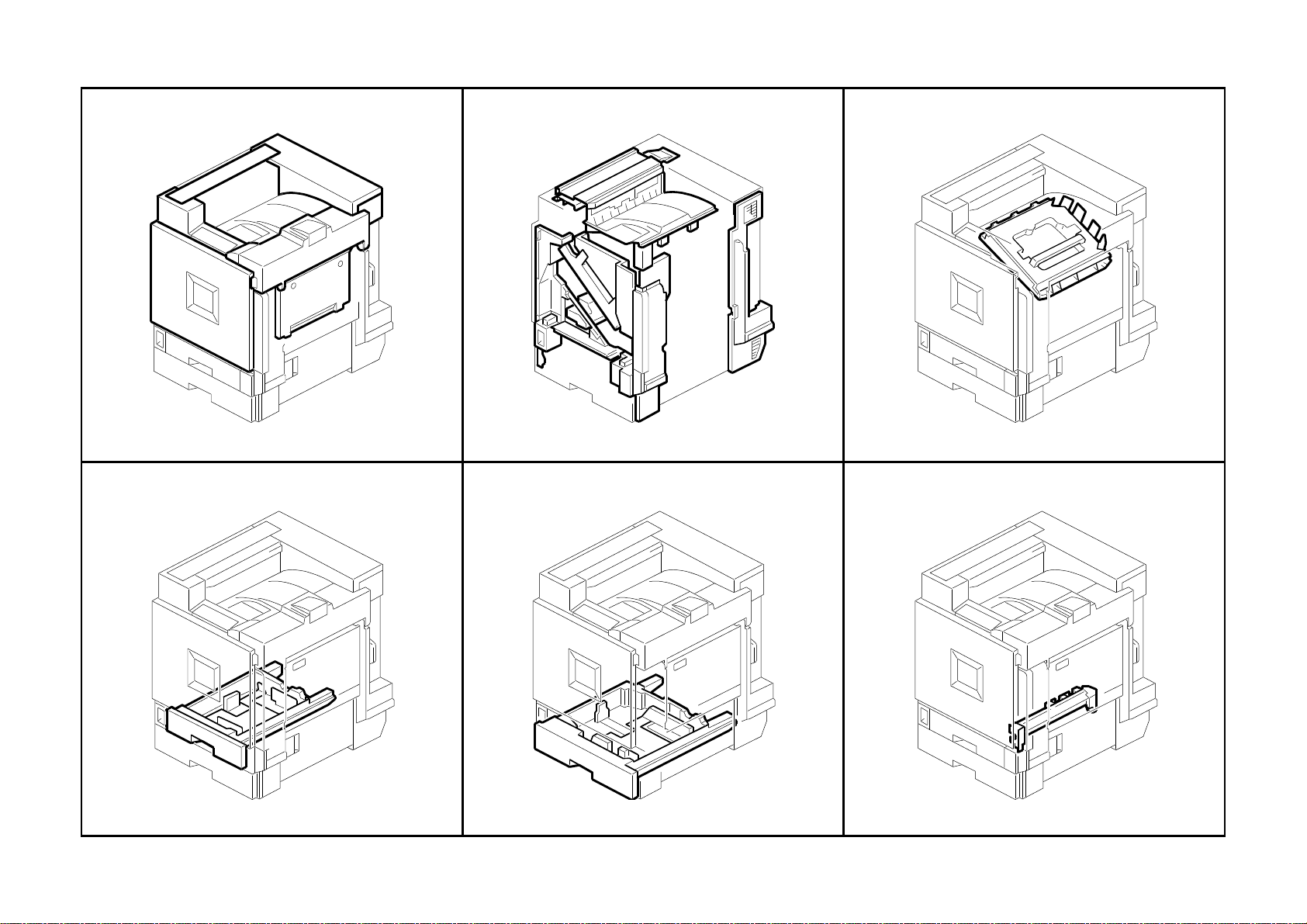
LOCATIONS OF UNITSLOCATIONS OF UNITS
LOCATIONS OF UNITS
LOCATIONS OF UNITS
LOCATIONS OF UNITS
1. Exterior 1 (G060)
4. 1st Cassette (G060)
See Page 9
2. Exterior 2 (G060)
See Page 11
5. 2nd Cassette (G060)
3. Laser Unit (G060)
See Page 13
6. 1st Paper Feed Section (G060)
See Page 15
G060 2 Parts Location and List
See Page 17
See Page 19
Page 17
LOCATIONS OF UNITSLOCATIONS OF UNITS
LOCATIONS OF UNITS
LOCATIONS OF UNITS
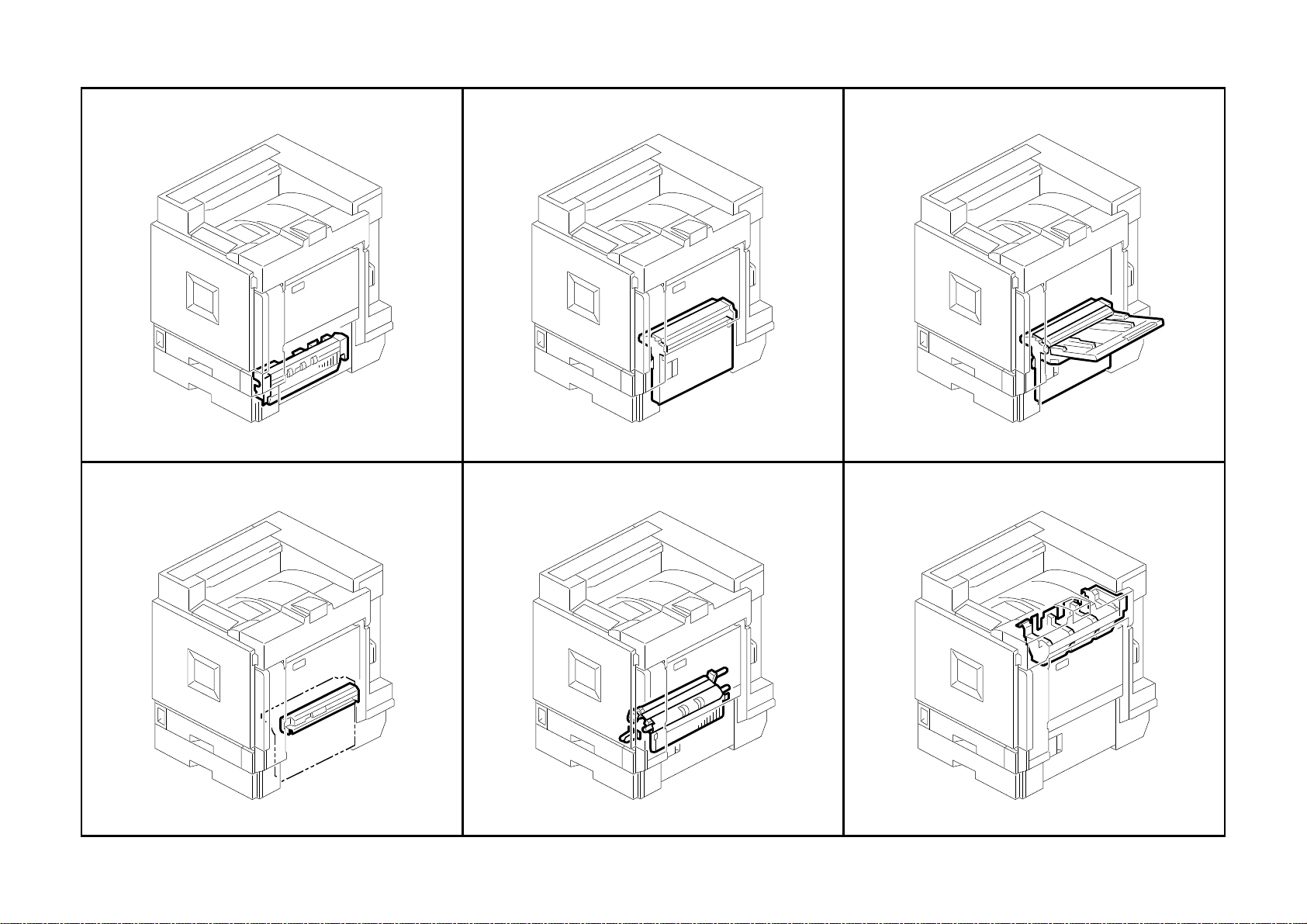
LOCATIONS OF UNITS
7. 2nd Paper Feed Section (G060)
See Page 21
10. Manual Paper Feed 2 (G060)
8. Vertical Transport Section (G060)
See Page 23
11. Paper Registration (G060)
9. Manual Paper Feed 1 (G060)
See Page 25
12. Color Toner Hopper (G060)
See Page 27
G060 3 Parts Location and List
See Page 29
See Page 31
Page 18
LOCATIONS OF UNITSLOCATIONS OF UNITS
LOCATIONS OF UNITS
LOCATIONS OF UNITS
LOCATIONS OF UNITS
13. Black Toner Hopper (G060)
See Page 33
16. Transfer Unit 2 (G060)
14. PCU/Development Unit (G060)
See Page 35
17. Transfer Unit 3 (G060)
15. Transfer Unit 1 (G060)
See Page 37
18. Transfer Unit 4 (G060)
See Page 39
G060 4 Parts Location and List
See Page 41
See Page 43
Page 19
LOCATIONS OF UNITSLOCATIONS OF UNITS
LOCATIONS OF UNITS
LOCATIONS OF UNITS
LOCATIONS OF UNITS
19. Fusing Unit 1 (G060)
See Page 45
22. Paper Exit Section 2 (G060)
20. Fusing Unit 2 (G060)
See Page 57
23. Paper Exit Section 3 (G060)
21. Paper Exit Section 1 (G060)
See Page 49
24. Waste Toner Transfer Section (G060)
See Page 51
G060 5 Parts Location and List
See Page 53
See Page 55
Page 20
LOCATIONS OF UNITSLOCATIONS OF UNITS
LOCATIONS OF UNITS
LOCATIONS OF UNITS
LOCATIONS OF UNITS
25. Drive Section 1 (G060)
28. Drive Section 4 (G060)
See Page 57
26. Drive Section 2 (G060)
See Page 59
29. Electrical Section 1 (G06 0)
27. Drive Section 3 (G060)
See Page 61
30. Electrical Section 2 (G06 0)
See Page 63
G060 6 Parts Location and List
See Page 65
See Page 67
Page 21
LOCATIONS OF UNITSLOCATIONS OF UNITS
LOCATIONS OF UNITSLOCATIONS OF UNITSLOCATIONS OF UNITS
31. Frame Section 1 (G060)
See Page 69
32. Frame Section 2 (G060)
See Page 71
G060 7 Parts Location and List
Page 22
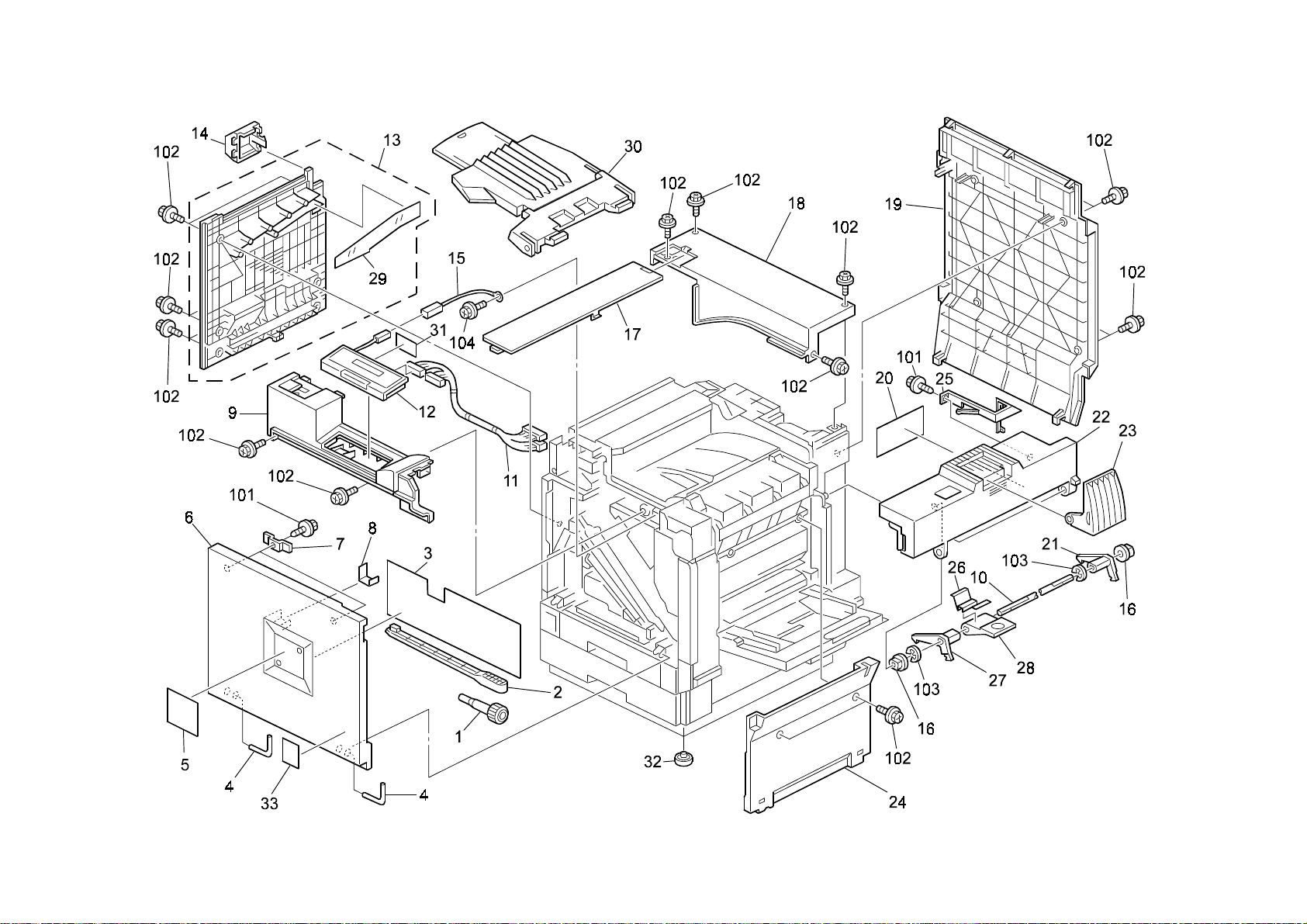
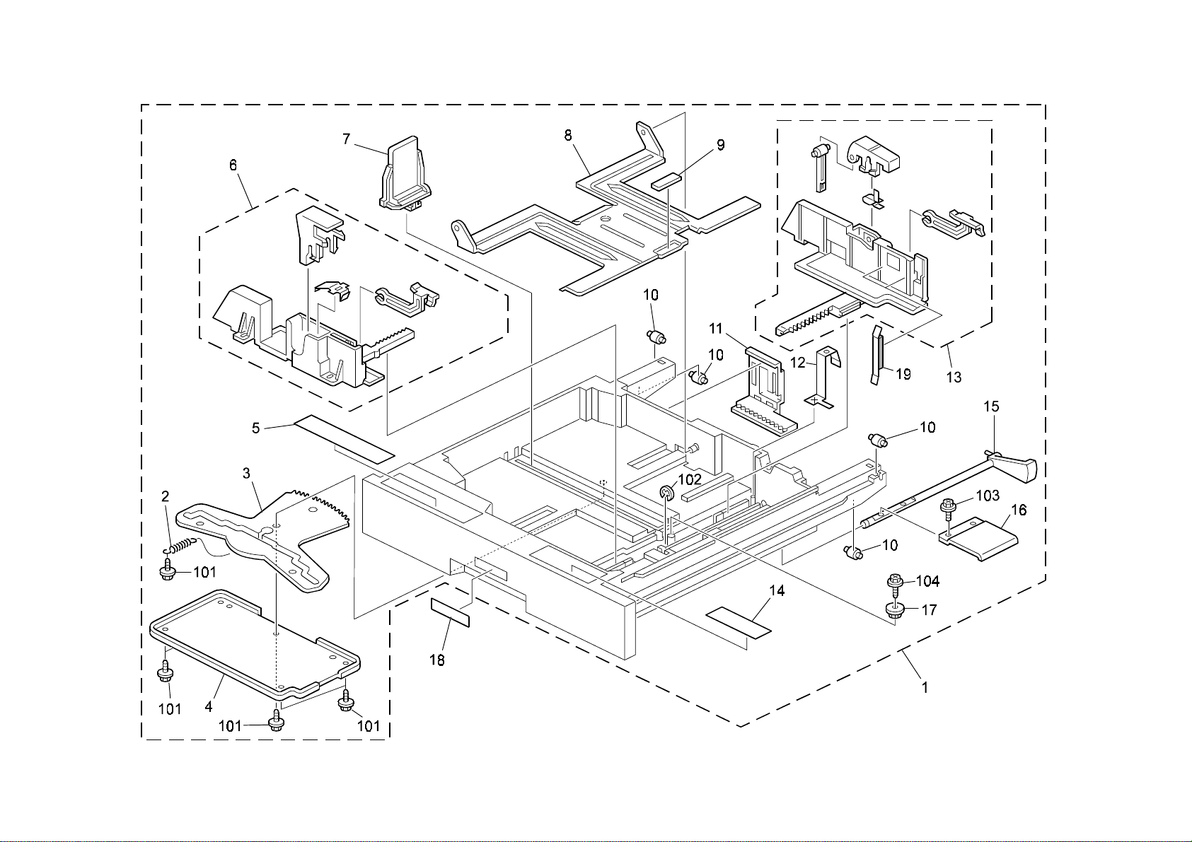
1.Exterior 1 (G060)
G060 8 Parts Location and List
Page 23

Q’ty Per
Index
Q’ty Per
Index
1.Exterior 1 (G060)
Q’ty Per
Index
Q’ty Per
Index
Rev. 09/26/2002
Part No.
No.
No.
1 G060 2989 Screw Driver 1
2 G060 1995 Cleaner - Dust Proof Glass 1
3 G077 1292 Sheet - Jam Removal 1
4 G020 1332 Hinge - Front Cover 4
5 G060 7005 Decal - Emblem (RIC) 1
5 G060 7405 Decal - Emblem (RIC AP828) 1
5 G060 7505 Decal - Emblem (SVN) 1
5 G060 7506 Decal - Emblem (GES NA) 1
5 G060 7605 Decal - Emblem (NSA) 1
5 G060 7606 Decal - Emblem (REX) 1
5 G060 7607 Decal - Emblem (GES EU) 1
5 G060 7705 Decal - Emblem (INF) 1
5 G060 7805 Decal - Emblem (LAN) 1
6 G060 1262 Front Cover 1
7 B024 1264 Magnet Catch 1
8 GA16 2001 Sheet - Front Cover 1
9 G060 1283 Upper Inner Cover 1
10 G060 1314 Stopper Pawl Shaft 1
11 G060 5484 Harness - Operation Panel 1
12 G060 7011 Operation Panel - LT 1
12 G060 7111 Operation Panel - A4 1
13 G060 1220 Lower Left Cover 1
14 G060 1289 Small Cover - Option 1
15 G024 5115 Ground Harness - Operation Panel 1
16 AA08 2101 Bushing - 6x10x6 2
17 G060 1288 Large Cover - Option 1
18 G060 1272 Upper Rear Cover 1
19 G077 1268 Rear Cover 1
20 GA00 3009 Sheet - Toner Supply 1
21 G060 1313 Rear Stopper Pawl 1
22 G060 1265 Right Upper Cover 1
23 G060 1293 Exit End Fence 1
24 G060 1224 Inner Cover - Manual Feed 1
25 G060 1319 Grounding Plate 1
26 G060 1320 Spring Plate - Grip 1
Part No.
Description
Description
Assembly
Assembly
Part No.
No.
No.
27 G060 1312 Front Stopper Pawl 1
28 G060 1318 Grip - Right Upper Cover 1
29 G060 1291 Cover Duct Mylar Film 1
30 G060 4490 Exit Tray 1
31 G060 1490 Seal - Operation Panel 1
32 AH01 0009 Rubber Pad - H5 7
33 GA00 3034 Decal - Energystar 1
101 0450 3008B Tapping Screw - M3x8
102 0451 3008H Tapping Screw - M3x8
103 0720 0040E Retaining Ring - M4
104 0451 3006B Tapping Screw - M3x6
Part No.
Description
Description
Assembly
Assembly
G060 9 Parts Location and List
Page 24
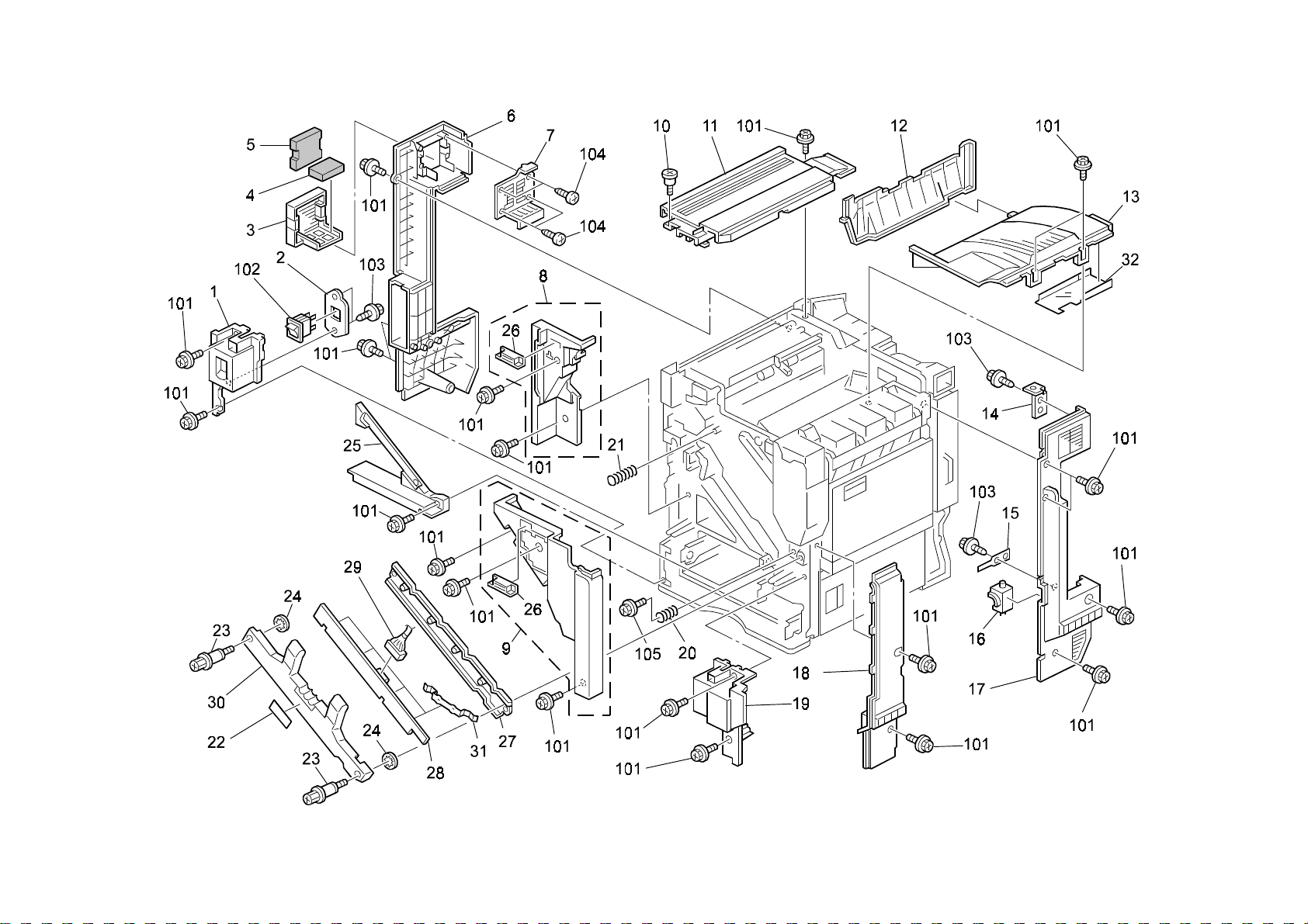
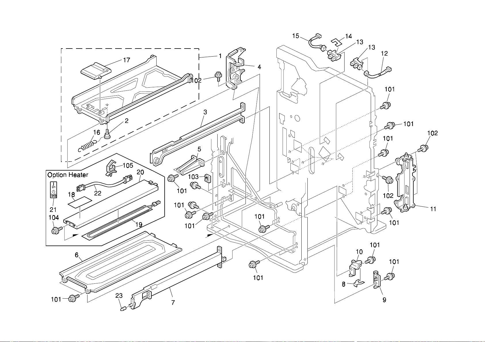
2.Exterior 2 (G060)
G060 10 Parts Location and List
Page 25

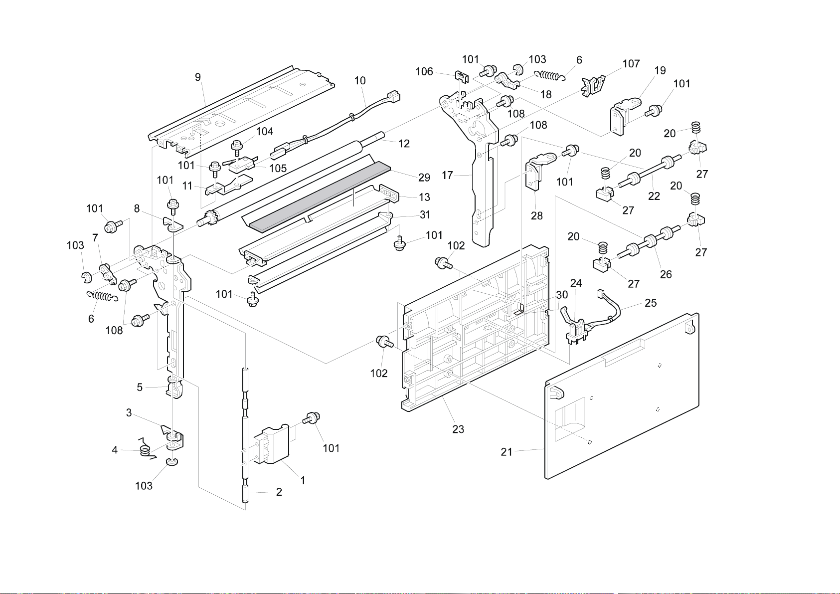
2.Exterior 2 (G060)
Index
No.
1 G060 1271 Front Cover - Left Lower 1
2 G060 5813 Bracket - Main Switch 1
3 G060 1300 Filter Case 1
4 GA01 2001 Lower Filter 1
5 GA01 2000 Upper Filter 1
6 G060 1269 Left Rear Cover 1
7 G060 1281 Louver - Left Rear Cover 1
8 G060 1208 Left Inner Cover 1
9 G060 1205 Right Inner Cover 1
10 AA14 3219 Stepped Screw 1
11 G060 1274 Upper Exit Cover 1
12 G060 1279 Exit Cover 1
13 G077 1275 Upper Cover - Exit Tray 1
14 G060 1280 Supporting Plate - Right Rear Cover 1
15 G060 2950 Spring Plate - Clutch Cover 1
16 G060 2949 Magnetic Clutch Cover 1
17 G077 1267 Right Rear Cover 1
18 G060 1287 Front Right Cover 1
19 G060 1266 Front Cover - Right Lower 1
20 G060 2482 Right Spring - Drum Stay 1
21 G060 2481 Left Spring - Drum Stay 1
22 GA00 3025 Decal - Drum Stay 1
23 G060 2460 Screw - M4X6 2
24 G060 2461 Nut - M7 2
25 G060 1285 Lower Inner Cover 1
26 AG07 1011 Magnet Catch 2
27 G060 2451 Drum Stay 1
28 G060 2457 Unit Detection Switch 1
29 G060 5489 Harness - Unit Detection Switch 1
30 G060 2455 Cover - Drum Stay 1
31 G060 2456 Spring Plate- Unit Detection Switch 4
32 G060 1278 Film - Upper Cover 1
Part No.
Description
Q’ty Per
Assembly
Rev. 07/02/2003
Index
No.
101 0451 3008H Tapping Screw - M3x8
102 1204 2533 Switch - AJ76200PZ02
103 0450 3008B Tapping Screw - M3x8
104 0452 3008B Tapping Screw - M3x8
105 0451 3006B Tapping Screw - M3x6
Part No.
Description
Q’ty Per
Assembly
G060 11 Parts Location and List
Page 26
3.Laser Unit (G060)
G060 12 Parts Location and List
Page 27

Q’ty Per
Index
Q’ty Per
Index
3.Laser Unit (G060)
Rev. 09/26/2002
No.
1 G077 1856 Imaging Unit 1
2 AA00 0218 Caution Decal 1
3 G060 1907 Cover Seal - 2 2
4 G060 1906 Cover Seal - 1 2
5 AA00 0217 Decal - LD 655 1
6 AX06 0212 Polygon Mirror Motor - DC24W 1
7 G060 1901 Positioning Pin 1
8 G060 5322 Sync Detector Board 4
9 AW10 0065 Thermistor - 103AT-4 2
10 G060 1908 Thermistor Plate 2
11 G060 1975 Lower Cover 1
12 AC01 5035 Shield Glass 4
13 G077 5522 Harness - FFC Y 1
14 G077 5523 Harness - FFC K 1
15 G077 5520 Harness - FFC M 1
16 G077 5521 Harness - FFC C 1
17 G077 1041 Imaging Unit Duct 1
18 G077 5473 Harness - Imaging Unit 1
19 G060 5494 Synchronization Detector Harness 1
Part No.
Description
Assembly
No.
101 0452 3008B Tapping Screw - M3x8
102 0452 3010B Tapping Bind Screw - M3x10
103 0451 3010B Tapping Screw - M3x10
104 1105 0488 Harness Clamp
Part No.
Description
Assembly
G060 13 Parts Location and List
Page 28
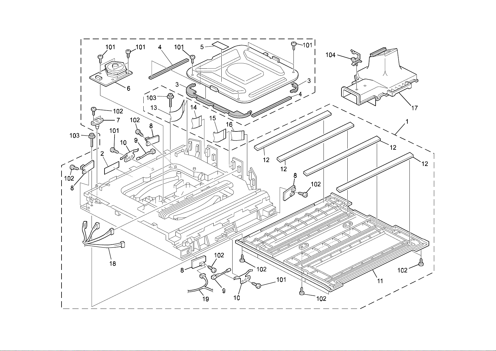
4.1st Cassette (G060)
G060 14 Parts Location and List
Page 29

4.1st Cassette (G060)
Index
No.
1 G080 2768 Paper Tray 1 1
2 GA00 3066 Decal: Paper Tray: No. 1 1
3 G060 2777 Front Side Fence 1
4 AF01 7023 End Fence 1
5 AF01 1049 Tray Bottom Plate 1
6 AF01 3006 Bottom Plate Pad 1
7 A232 2987 Roller - Paper Tray 4
8 G060 2775 Spring Plate - Paper Tray 1
9 G060 2778 Rear Side Fence 1
10 A204 2972 Bottom Lift Lever 1
11 G060 2774 Lift Shaft 1
12 GA00 3014 Decal - Paper Tray 1
13 G060 2793 Side Fence Holder 2
Part No.
Description
Q’ty Per
Assembly
Rev. 05/08/2003
Index
No.
101 0720 0060B Retaining Ring - M6
102 0450 4008B Tapping Screw - 4x8
103 0314 0060B Philips Pan Head Screw - M4x6
Part No.
Description
Q’ty Per
Assembly
G060 15 Parts Location and List
Page 30
5.2nd Cassette (G060)
G060 16 Parts Location and List
Page 31

5.2nd Cassette (G060)
Index
No.
1 G060 2772 Paper Tray 2 1
2 G060 2806 Tension Spring - Paper Size Sensor Board 1
3 G060 2796 Link - Paper Size Sensor Board 1
4 G060 2798 Cover - Paper Size Sensor 1
5 GA00 3012 Decal - Paper Tray 2 Left 1
6 G060 2781 Front Side Fence - Universal 1
7 AF01 7024 End Fence - Universal 1
8 AF01 1049 Tray Bottom Plate 1
9 AF01 300 6 Bottom Plate Pad 1
10 A232 2987 Roller - Paper Tray 4
11 G060 2797 Paper Size Sensor Board 1
12 G060 2775 Spring Plate - Paper Tray 1
13 G060 2782 Rear Side Fence - Universal 1
14 GA00 3013 Decal - Paper Tray 2 Right 1
15 G060 2774 Lift Shaft 1
16 A204 2972 Bottom Lift Lever 1
17 AB01 3868 Gear - 16Z 1
18 GA00 3014 Decal - Paper Tr a y 1
19 G060 2793 Side Fence Holder 2
Part No.
Description
Q’ty Per
Assembly
Index
No.
101 0450 3008B Tapping Screw - M3x8
102 0720 0060B Retaining Ring - M6
103 0451 4006B Tapping Screw - 4x6
104 0450 4008B Tapping Screw - 4x8
Part No.
Description
Q’ty Per
Assembly
G060 17 Parts Location and List
Page 32

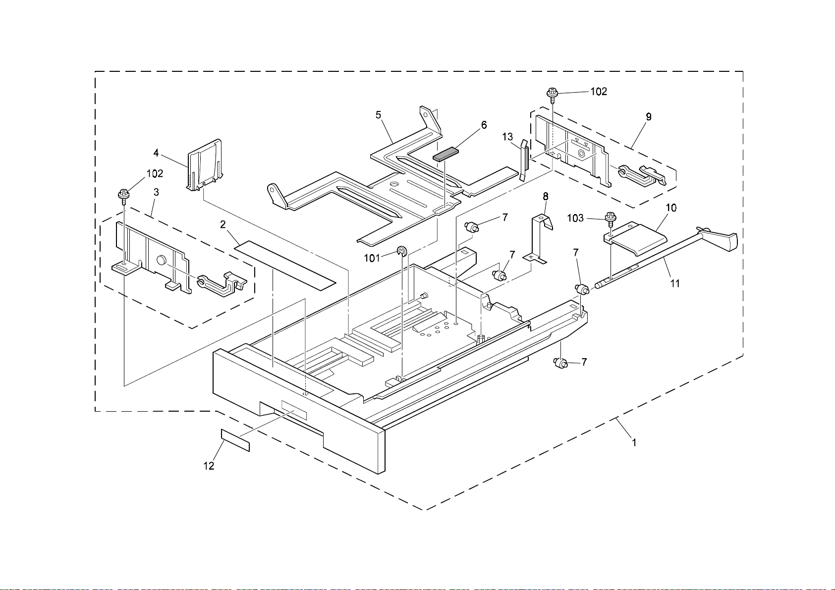
6.1st Paper Feed Section (G060)
G060 18 Parts Location and List
Page 33

6.1st Paper Feed Section (G060)
Index
No.
1 G080 2700 Paper Feed Unit 1 1
2 G060 2716 Feed Stay 1
3 AF03 0049 Pick-up Roller 1
4 AB01 1188 Gear - 21Z 1
5 AA10 0014 Retaining Ring C - Separate 2
6 AF03 1049 Feed Roller 1
7 AB01 1218 Gear - Roller Clutch 1
8 AA08 2101 Bushing - 6x10x6 1
9 A232 2763 Pick-up Arm 1
10 AA06 0691 Tension Spring 1
11 AW02 0120 Photointerruptor - Flat 2
12 G060 5483 Harness - Paper Feed Unit 1
13 AA08 3014 One-way Clutch 1
14 AA14 0655 Shaft - Paper Feed 1
15 AA08 2102 Bushing - 6x10x6 3
16 A232 2764 Rear Grounding Plate 1
17 AA14 0656 Shaft - Gear 1
18 5206 2686 Snap Ring 2
19 A232 2776 Release Lever 1
20 AB01 0106 Gear - 24Z 1
21 AB01 0107 Gear - 23Z 1
22 A232 2762 Paper End Feeler 1
23 A232 2766 Feed Mylar 1
24 G060 2689 Shaft - Separation Driven 1
25 AF03 2049 Separation Roller 1
26 G060 2900 Torque Limiter - 40MN・M 18MM 1
27 G060 2727 Stay - Paper Separation 1 1
28 AA06 0693 Tension Spring 1
29 A232 2774 Pressure Lever 1
30 AA06 0692 Tension Spring 1
31 A232 2775 Link Lever 1
32 G060 2786 Rear Feed Mylar 1
33 G060 2724 Upper Guide - Paper Feed Unit 1
Part No.
Description
Q’ty Per
Assembly
Rev. 05/08/2003
Index
No.
101 0805 0089 Retaining Ring - M4
102 0720 0040B Retaining Ring - M4
103 0451 3006B Tapping Screw - M3x6
Part No.
Description
Q’ty Per
Assembly
G060 19 Parts Location and List
Page 34

7.2nd Paper Feed Section (G060)
Rev. 07/02/2003
G060 20 Parts Location and List
Page 35

7.2nd Paper Feed Section (G060)
Index
Index
No.
No.
1 G060 2750 Paper Feed Unit 2 1
2 A232 2780 Stay - Paper Feed 1
3 AF03 0049 Pick-up Roller 1
4 AA10 0014 Retaining Ring C - Separate 2
5 AF03 1049 Feed Roller 1
6 AB01 1218 Gear - Roller Clutch 1
7 AB01 1188 Gear - 21Z 1
8 AA08 2101 Bushing - 6x10x6 1
9 A232 2763 Pick-up Arm 1
10 AA06 0691 Tension Spring 1
11 AF02 0404 Transport Roller 1
12 AW02 0120 Photointerruptor - Flat 2
13 G060 5483 Harness - Paper Feed Unit 1
14 AA08 3014 One-way Clutch 1
15 AA14 0655 Shaft - Paper Feed 1
16 AA08 2104 Bushing - 8x12x7 2
17 AA08 2102 Bushing - 6x10x6 3
18 A232 2764 Rear Grounding Plate 1
19 5206 2686 Snap Ring 1
20 A232 2776 Release Lever 1
21 AA14 0656 Shaft - Gear 1
22 AB01 0107 Gear - 23Z 1
23 A232 2774 Pressure Lever 1
24 AA06 0693 Tension Spring 1
25 AB01 0106 Gear - 24Z 1
26 A232 2775 Link Lever 1
27 A232 2762 Paper End Feeler 1
28 A232 2766 Feed Mylar 1
29 G060 2725 Stay - Paper Separation 1
30 A232 2765 Front Grounding Plate 1
31 G060 2689 Shaft - Separation Driven 1
32 G060 2900 Torque Limiter - 40MN MM8 1
33 AF03 2049 Separation Roller 1
34 G060 2629 Vertical Transport Guide 1
35 G060 2730 Guide Plate 1
Part No.
Part No.
Description
Description
Q’ty Per
Q’ty Per
Assembly
Assembly
Index
Index
No.
No.
36 B004 2782 Rear Feed Mylar 1
37 AA06 0692 Tension Spring 1
101 0805 0089 Retaining Ring - M4
102 0720 0060B Retaining Ring - M6
103 0720 0040B Retaining Ring - M4
104 0451 3006B Tapping Screw - M3x6
Part No.
Part No.
Description
Description
Q’ty Per
Q’ty Per
Assembly
Assembly
G060 21 Parts Location and List
Page 36
8.Vertical Transport Section (G060)
Rev. 09/26/2002
G060 22 Parts Location and List
Page 37

Q’ty Per
Index
Q’ty Per
Index
8.Vertical Transport Section (G060)
Rev. 09/18/2003
No.
1 G060 26 90 Lever - Vertical Transport 1
2 G060 26 91 Grip Shaft 1
3 G060 2672 Hook - Lower Vertical Transport 1
4 G060 2674 Torsion Spring - Vertical Transport 1
5 G060 2659 Front Side Plate - Paper Feed 1
6 G060 2602 Spring - Registration 2
7 G060 2650 Front Bushing - M6 1
8 G060 2671 Hook - Upper Vertical Transport 1
9 G060 2669 Cover - Upper Registration 1
10 G060 5501 Harness - Transport/Safety Switch 1
11 G060 2680 Bracket - Micro Switch 1
12 G060 2686 Registration Driven Roller 1
13 G060 2612 Guide Plate - Upper Registration 1
17 G060 2665 Rear Side Plate - Paper Feed 1
18 G060 2651 Rear Bushing - M6 1
19 G060 2667 Vertical Transport Hinge 1
20 AA06 3616 Spring - 8n 4
21 G060 2668 Cover - Lower Vertical Transport 1
22 AF02 3022 Driven Roller - M2xMM17 1
23 G060 2643 Guide Plate - Vertical Transport 1
24 AW02 0069 Photointerruptor 1
25 G060 5506 Sensor Harness - Paper Feed Unit 1
26 AF02 3023 Driven Roller - M3xMM17 1
27 G060 2652 Bushing - M4 4
28 G060 2683 Lower Vertical Transport Hinge 1
29 G060 2840 Guide - Paper Dust Remover 1
30 G012 3897 Film – Toner End Sensor Harness 2
31 G060 2613 Guide Plate – Middle Registration 1
Part No.
Description
Assembly
No.
101 0451 3006B Tapping Screw - M3x6
102 0450 3008B Tapping Screw - M3x8
103 0720 0040B Retaining Ring - M4
104 0451 3014B Tapping Screw - M3-14
105 1204 2521 Micro Switch
106 1105 0328 Harness Clamp - ES-0505
107 1105 0487 Harness Clamp
108 0452 3008B Tapping Screw - M3x8
Part No.
Description
Assembly
G060 23 Parts Location and List
Page 38

9.Manual Paper Feed 1 (G060)
G060 24 Parts Location and List
Page 39

Q’ty Per
Index
Q’ty Per
Index
9.Manual Paper Feed 1 (G060)
Rev. 09/26/2002
No.
* G077 2531 Vertical Transport Unit 1
1 G060 2940 Cover - Lower Manual Feed 1
2 G060 2953 Torsion Spring - Left 1
3 GA00 3044 Decal - Vertical Transport 1
4 G060 2952 Torsion Spring - Right 1
5 G060 2973 Front Shaft - Manual Feed Table 1
6 G060 2974 Rear Shaft - Manual Feed Table 1
7 G060 2856 Manual Feed Table Ass'y 1
8 G060 2866 Front Side Fence 1
9 G060 2867 Rear Side Fence 1
10 GA00 3010 Decal - Manual Feed 1
11 G060 2905 Paper Guide - Manual Feed Table 1
12 G060 2865 Cover - Manual Feed Table 1
13 G011 3305 Gear - 16T 1
14 A232 6083 Rear Rack 1
15 A232 6082 Front Rack 1
16 G060 2869 Paper Size Sensor 1
17 G060 2908 Pad - Side Fence 2
Part No.
Description
Assembly
No.
101 0450 3008H Tapping Screw M3x8
102 0451 3006B Tapping Screw - M3x6
Part No.
Description
Assembly
G060 25 Parts Location and List
Page 40

10.Manual Paper Feed 2 (G060)
G060 26 Parts Location and List
Page 41

10.Manual Paper Feed 2 (G060)
Index
No.
* G077 2531 Vertical Transport Unit 1
1 G060 2930 Housing Cover 1
2 AA10 0014 Retaining Ring C - Separate 2
3 AF03 1046 Feed Roller - Manual Feed 1
4 AA08 2101 Bushing - 6x10x6 3
5 AA14 0730 Feed Shaft 1
6 G060 2914 Stopper Plate 1
7 AB01 1387 Gear - 23Z 1
8 AF03 0049 Pick-up Roller 1
9 AA06 3568 Pressure Spring 1
10 G060 2932 Pick-up Arm - Manual Feed 1
11 G060 2937 DC Solenoid - Pick-up 1
12 G060 5481 Harness - Manual Feed Unit 1
13 A166 2849 Drive Support Plate 1
14 AB01 1418 Gear - 27Z 1
15 AX20 0134 Magnetic Clutch - 245MN.M 1
16 AA08 3018 Roller Clutch - 6x14x10 1
17 AW02 0120 Photointerruptor - Flat 1
18 A134 2661 Feeler Roller 1
19 G060 2931 Feeler - Paper End 1
20 G060 2948 Grounding Plate - Reverse 1
21 AF01 3016 Bott om Plate Pad 1
22 G060 2874 Guide Plate - Separator 1
23 AF03 2046 Separation Roller - Manual Feed 1
24 G060 2900 Torque Limiter - 40MN M MM18 1
25 AA06 3499 Pressure Spring 1
26 G060 2871 Separation Driven Shaft 1
27 AB01 1417 Gear - Separation Driven 1
28 G077 2876 Shaft - Separator Drive 1
29 GA00 3029 Decal - Vertic al Tr ans port 1
30 G060 2982 Feed Guide 1
Part No.
Description
Q’ty Per
Assembly
Index
No.
101 0451 3008H Tapping Screw - M3x8
102 0451 3006B Tapping Screw - M3x6
103 0450 3008B Tapping Screw - M3x8
104 0720 0040B Retaining Ring - M4
Part No.
Description
Q’ty Per
Assembly
G060 27 Parts Location and List
Page 42
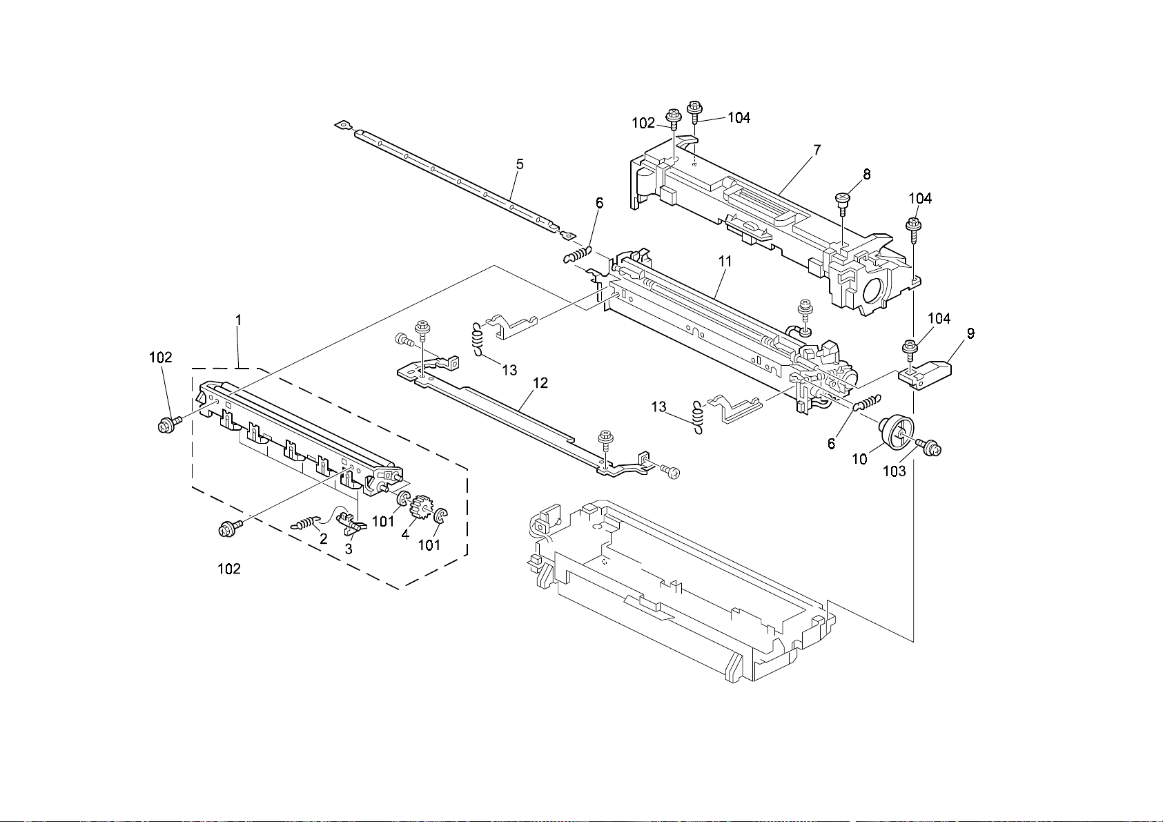
11.Paper Registration (G060)
Rev. 05/08/2003
G060 28 Parts Location and List
Page 43

11.Paper Registration (G060)
Index
No.
1 AA08 2104 Bushing - 8x12x7 2
2 AA08 2101 Bushing - 6x10x6 2
3 G060 1277 Bracket - Front Cover Hinge 1
4 G060 2678 Front Registration Bushing - M8 1
5 G060 2685 Registration Drive Roller 1
6 5215 2621 Snap Ring - M6 2
7 G060 2679 Rear Registration Bushing - M8 1
8 G060 2606 Guide Plate - Lower Registration 1
9 G060 2607 Registration Guide 1
10 G060 5480 Harness - Registration Sensor 1
11 AW01 0048 Photosensor - GP2A28N1 1
12 G060 2609 Bracket - Registration Sensor 1
13 G060 2627 Transport Drive Roller 1
14 G060 2625 Duplex Guide Plate - Upper Exit 1
15 AW02 0096 Photointerruptor 1
16 G060 5482 Harness - Paper Feed Unit Sensor 1 1
17 G060 2634 Bracket - Paper Feed Sensor 1
18 G060 2622 Duplex Guide Plate - Lower Exit 1
19 G060 2652 Bushing - M4 2
20 AF02 2135 Driven Roller - M3x16 1
21 AA06 3408 Spring - 8n 2
22 G060 2681 Knob - Vertical Transport 1
23 G060 2626 Transport Drive Roller - Middle 1
24 G060 2617 Middle Guide Plate 1
25 G060 2619 Lower Middle Guide Plate 1
26 G060 2620 Entrance Middle Guide 1
27 G060 2604 Sheet - Registration Guide 1
28 G060 2633 Guide: Middle: Lower 1
29 G060 2618 Guide Plate: Middle: Lower: Adhesion 1
Part No.
Description
Q’ty Per
Assembly
Rev. 05/08/2003
Index
No.
101 0451 3006B Tapping Screw - M3x6
102 0450 3006B Tapping Screw - M3x6
103 0313 0060B Philips Pan Head Screw - M3x6
104 1105 0522 Edge Saddle - LES0510
105 1105 0487 Harness Clamp
106 0720 0040B Retaining Ring - M4
107 0720 0060B Retaining Ring - M6
Part No.
Description
Q’ty Per
Assembly
G060 29 Parts Location and List
Page 44

12.Color Toner Hopper (G060)
Rev. 09/26/2002
G060 30 Parts Location and List
Page 45

12.Color Toner Hopper (G060)
Index
No.
1 G060 3201 Toner Cartridge Holder - Color 1
2 G060 3211 Tube - Valve K 1
3 AA06 3627 Coil - Tube Guard 1
4 G060 3240 Valve 1
5 G060 3301 Air Pump - Toner Supply 1
6 AW14 0009 Humidity Sensor - RHU-232 1
7 AW50 0023 Push Switch 1
8 AA15 3461 Holder Seal 3
9 AA06 3626 Compression Spring - 4.9N 3
10 G060 3216 Toner Nozzle 3
11 G060 3241 Tube - M Toner Supply 1
12 G060 3238 Tube - C Toner Supply 1
13 G060 3237 Tube - Y Toner Supply 1
14 GA00 3016 Decal - Y Toner Supply 1
15 GA00 3018 Decal - C Toner Supply 1
16 GA00 3017 Decal - M Toner Supply 1
17 G060 5599 Toner Cartridge Stopper 3
18 G060 1094 Holder - Toner Supply Unit 1
19 G060 3219 Toner Cartridge Holder 3
20 G060 3232 Base - Toner Cartridge Stopper 3
21 G012 4617 Stepped Screw - M3 2
22 AA06 3656 Guide Coil – M Tube 1
Part No.
Description
Q’ty Per
Assembly
Index
No.
101 0451 3006B Tapping Screw - M3x6
102 1105 0522 Edge Saddle - Les0510
103 0450 3008B Tapping Screw - M3x8
104 1105 0511 Harness Clamp - LWS-0306ZC
105 1105 0487 Harness Clamp
106 0451 3008B Tapping Screw - M3x8
Part No.
Description
Rev. 09/26/2002
Q’ty Per
Assembly
G060 31 Parts Location and List
Page 46
13.Black Toner Hopper (G060)
G060 32 Parts Location and List
Page 47

13.Black Toner Hopper (G060)
Index
No.
1 G060 3202 Toner Cartridge Holder - BK 1
2 G060 3211 Tube - Valve K 1
3 G060 3236 Tube - K Toner Supply 1
4 G060 5599 Toner Cartridge Stopper 1
5 GA00 3019 Decal - K Toner Supply 1
6 AA06 3627 Coil - Tube Guard 1
7 AA15 3461 Holder Seal 1
8 AA06 3626 Compression Spring - 4.9N 1
9 G060 3216 Toner Nozzle 1
10 G060 5492 Harness - ID 1
11 G060 3219 Toner Cartridge Holder 1
12 G060 3232 Base - Toner Cartridge Stopper 1
13 G060 1196 Upper Guide Rail 3
14 G060 1198 PCU Duct 1
15 GA00 3033 Decal - Shieldi ng Pl ate K 1
16 G060 3318 Shielding Plate - K Development 1
17 GA00 3030 Decal - Shieldi ng Pl ate Y 1
18 G060 3321 Shielding Plate - Y Development 1
19 GA00 3032 Decal - Shieldi ng Pl ate C 1
20 G060 3319 Shielding Plate - C Development 1
21 GA00 3031 Decal - Shieldi ng Pl ate M 1
22 G060 3320 Shielding Plate - M Development 1
23 G060 3334 Toner Cartridge Holder 1
24 G060 3233 Toner Cartridge Holder Filter 1
Part No.
Description
Q’ty Per
Assembly
Index
No.
101 0450 3008B Tapping Screw - M3x8
102 1105 0522 Edge Saddle - LES0510
103 0451 3008B Tapping Screw - M3x8
104 0451 3006B Tapping Screw - M3x6
Part No.
Description
Q’ty Per
Assembly
G060 33 Parts Location and List
Page 48

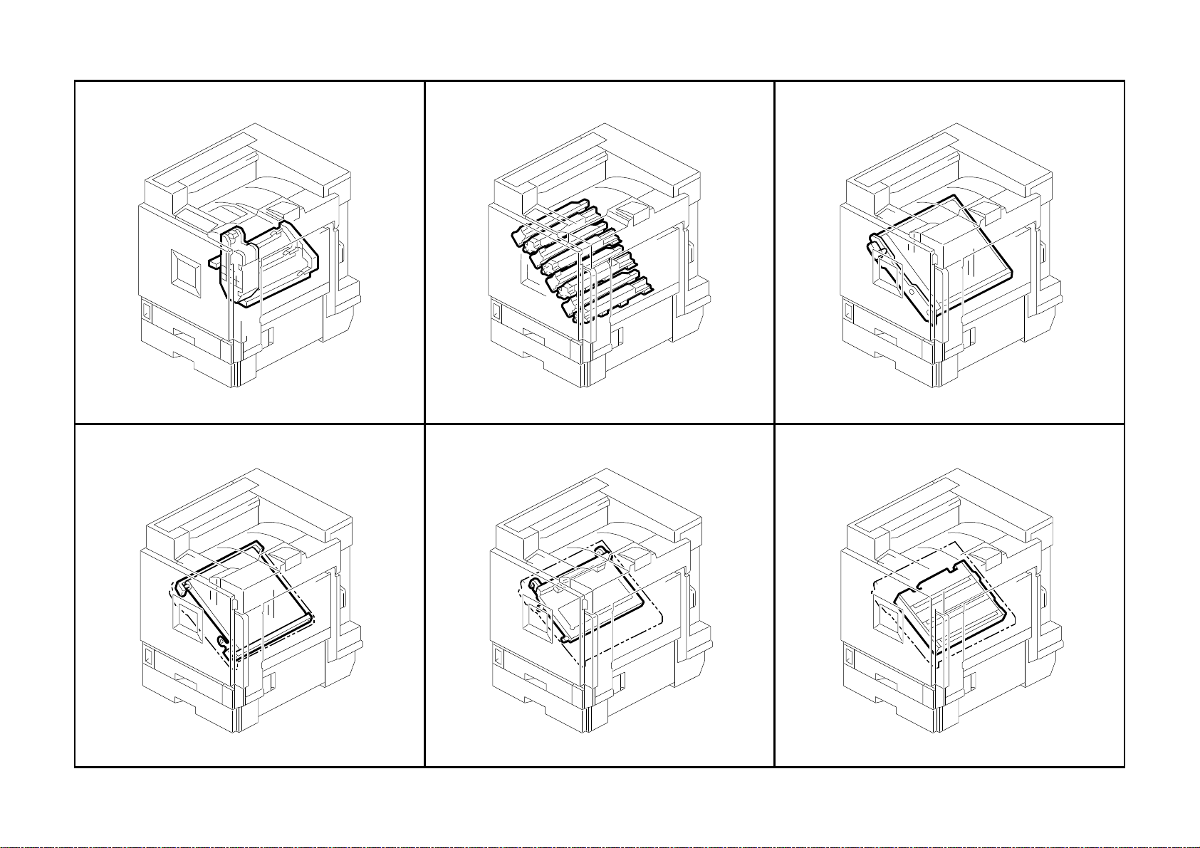
14.PCU/Development Unit (G060)
G060 34 Parts Location and List
Page 49

14.PCU/Development Unit (G060)
Index
No.
1 G060 2219 PCU - CMY 3
2 G060 3013 Development Unit - Y 1
3 G060 3011 Development Unit - C 1
4 G060 3012 Development Unit - M 1
Part No.
Description
Q’ty Per
Assembly
Index
No.
Part No.
Description
Q’ty Per
Assembly
G060 35 Parts Location and List
Page 50

15.Transfer Unit 1 (G060)
Rev. 09/26/2002
G060 36 Parts Location and List
Page 51

Q’ty Per
Index
Q’ty Per
Index
15.Transfer Unit 1 (G060)
Rev. 09/ 18/2003
No.
1 G060 3815 Transfer Cleaning Unit 1
2 G060 3965 Transfer Cleaning Blade 1
3 G060 3675 Rear Cleaning Blade Bushing 1
4 G060 3974 Rear Gear - Cleaning Roller 1
5 AA08 2101 Bushing - 6x10x6 2
6 G060 3971 Transfer Cleaning Roller 1
7 G060 3976 Seal - Transport Screw 1
8 G060 3961 Lower Blade Seal - 340x11 1
9 G060 3977 Gear - Transport Screw 1
10 G060 3978 Idle Gear 1
11 G060 3972 Spring Plate - Cleaning Bias 1
12 G060 3973 Front Gear - Cleaning Roller 1
13 G060 3970 Pressure Spring - Cleaning Blade 1
14 G060 3968 Front Bushing - Cleaning Blade 1
15 G077 3923 Release Lever 1
16 G060 3695 Drum Stay 1
17 G060 3909 Compression Spring - Front 1
18 A250 4280 Fusing Unit Screw 1
19 G077 38 41 Transfer Unit 1
21 G060 3976 Seal - Transport Screw 1
22 G060 3962 Blade Side Seal - 3.5x22.5x3 2
23 G060 3676 Cleaning Blade Pressure Spring 1
24 G060 3999 Upper Cleaning Seal - 16x348 1
25 G060 3951 Toner Collection Coil 1
26 G060 3954 Toner Collection Coil - Cleaning 1
27 G060 3951 Toner Collection Coil 1
28 A697 4150 Stepped Screw - M5 1
29 G060 3687 Stay - Transfer Unit 1
Part No.
Description
Assembly
No.
101 0450 3008B Tapping Screw - M3x8
102 0451 3006B Tapping Screw - M3x6
103 0720 0040E Retaining Ring - M4
Part No.
Description
Assembly
G060 37 Parts Location and List
Page 52

16.Transfer Unit 2 (G060)
Rev. 09/18/2003
G060 38 Parts Location and List
Page 53

16.Transfer Unit 2 (G060)
Index
Index
No.
No.
1 G060 5420 ID Sensor 1
2 G060 3915 Left Bracket 1
3 G060 3875 Spring Plate - Left 1
4 G060 3895 Spacer - Joint 2
5 A250 4280 Fusing Unit Screw 1
6 G060 3696 Exit Guide Plate - Transfer 1
7 G060 3703 Drive Roller 1
8 G060 3883 Roller 2
9 G060 3885 Left Stay 1
10 G060 3894 Cam - Front 2
11 G060 3893 Stay - ON-OFF 1
12 G077 3850 Transfer Belt 1
13 G060 3910 Bias Roller 1
14 AB01 0114 Gear - Bias Roller 1
15 G060 3914 Cover - Bias Roller 1
16 G060 3907 Registration Guide Plate 1
17 G060 3897 Bracket - Rear Driven 1
18 AA08 2103 Bushing - Transfer Driven 2
19 G060 3919 Spacer - Gear 2
20 G060 3899 Gear - ON-OFF 1
21 G060 3903 Compression Spring - Driven 2
22 G060 3699 Collar - Driven 2
23 G060 3681 Driven Roller 1
24 G060 3908 Upper Registration Guide 1
25 G060 3906 Right Bracket 1
26 AB01 0119 Gear - Driven Roller 1
27 G060 3912 Spring Plate - Bias Roller 1
28 G060 3890 Bracket - Front Driven 1
29 G060 3896 Joint - Front 1
30 G060 3958 Spring Plate - Right Bracket 1
31 G060 3876 Spring Plate - Right 1
32 G060 3677 Lower Transfer Entrance Guide 1
33 G060 3949 Spring Plate - Left Stay 1
34 AA08 2115 Bushing 5x10x5 2
35 G060 3707 Sheet: Stay: Left 4
Part No.
Part No.
Description
Description
Q’ty Per
Q’ty Per
Assembly
Assembly
Rev. 10/31/2003
Index
Index
No.
No.
101 0450 3008B Tapping Screw - M3x8
102 0451 3006B Tapping Screw - M3x6
103 0720 0040E Retaining Ring - M4
104 0720 0060E Retaining Ring - M6
105 0353 0040B Screw - M3X4
106 0805 3492 Bushing - 8x16x5
Part No.
Part No.
Description
Description
Q’ty Per
Q’ty Per
Assembly
Assembly
G060 39 Parts Location and List
Page 54

17.Transfer Unit 3 (G060)
Rev. 09/18/2003
G060 40 Parts Location and List
Page 55

Q’ty Per
Index
Q’ty Per
Index
17.Transfer Unit 3 (G060)
Rev. 09/18/2003
No.
1 G060 3950 Feeler - On-Off 1
2 G060 3698 Stay 1
3 G077 3697 Shaft - Release 1
4 G060 3981 Cleaning Roller 1
5 G060 3988 Bushing - Cleaning 2
6 G060 3984 Bracket - Cleaning 1
7 G060 5488 Harness - Transfer Unit 2 1
8 G060 3853 Tension Spring - Left Frame 2
9 G060 3860 Electrode Plate - Transfer Brush K 1
10 G060 3924 Compression Spring - Back Up 3N 2
11 G060 3852 Bushing - Back-up 2
12 G060 3690 Left Frame 1
13 G060 3680 Back Up Roller - Transfer 1
14 G060 3693 Ground Plate - Transfer K 1
15 G060 3930 Transfer Brush 1
16 G060 5511 Harness - High Voltage Line T-K 1
17 G060 3945 Timing Belt - Transfer Belt Drive 1
18 G060 3702 Gear - Transfer Belt Drive 1
19 G060 3940 Bracket - Tightener 1
20 G060 3997 Tension Spring - On-off 1
21 G060 3942 Tension Spring - Tightener 1
22 G060 5472 Harness - Transfer Unit 1 1
23 G060 3712 Torsion Spring 1
25 G060 3705 Cushion – Transfer Brush 1
Part No.
Description
Assembly
No.
101 0720 0030E Retaining Ring - M3
102 0450 3008B Tapping Screw - M3x8
103 1102 8969 Connector - QR/P17-18S-B1
104 1105 0522 Edge Saddle - LES0510
105 1105 0511 Harness Clamp - LWS-0306ZC
106 0720 0060E Retaining Ring - M6
107 0451 3006B Tapping Screw - M3x6
108 1105 0516 Clamp
109 0720 0040 Retaining Ring – M4
Part No.
Description
Assembly
G060 41 Parts Location and List
Page 56

18.Transfer Unit 4 (G060)
Rev. 09/26/2002
G060 42 Parts Location and List
Page 57

18.Transfer Unit 4 (G060)
Index
No.
1 G060 3852 Bushing - Back-up 6
2 G060 3924 Compression Spring - Back Up 3N 2
3 G060 3855 Compression Spring - Back-up 4
4 G060 3865 Back-up Roller 1
5 G060 3930 Transfer Brush 3
6 G060 3704 Right Frame 1
7 G060 3871 Electrode Plate - Transfer Brush M 1
8 G060 3870 Electrode Plate - Transfer Brush Y1 1
9 G060 3956 Rear Spring Plate - Transfer 1
10 G060 3957 Grounding Plate - PP 1
11 G060 3869 Ground Plate 1
12 G060 3955 Front Spring Plate - Transfer 1
13 G060 3873 Ground Plate - Back-up Roller 1
14 G060 3872 Electrode Plate - Transfer Brush Y2 2
15 G060 5512 Harness - High Voltage Line T-Y 1
16 GZ32 0007 Power Pack - TPACL 1
17 G060 3671 Back Up Roller - Transfer 2
18 G060 3705 Cushion – Transfer Brush 3
Part No.
Description
Q’ty Per
Assembly
Index
No.
101 0450 3008B Tapping Screw - M3x8
Part No.
Description
Rev. 09/26/2002
Q’ty Per
Assembly
G060 43 Parts Location and List
Page 58
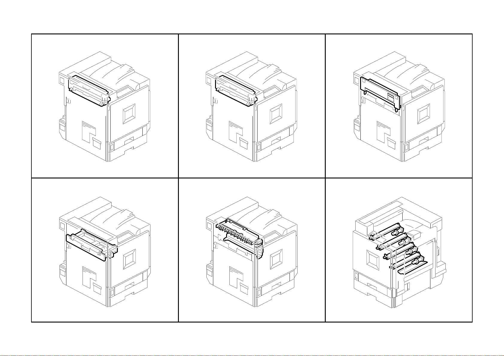
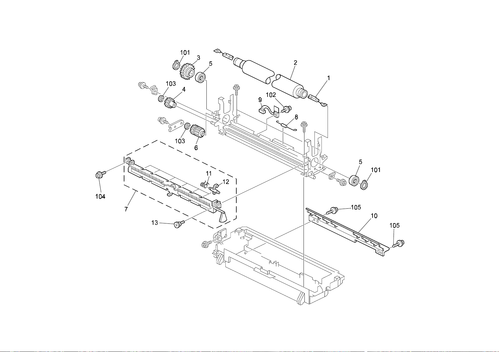
19.Fusing Unit 1 (G060)
G060 44 Parts Location and List
Page 59

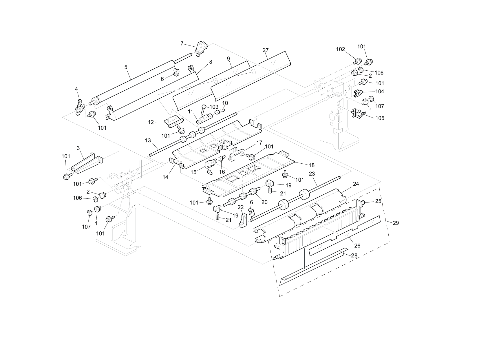
19.Fusing Unit 1 (G060)
Index
No.
1 G060 4022 Oil Supply Roller Ass'y 1
2 AA06 0932 Tension Spring 5
3 AE04 4051 Fusing Belt Stripper 5
4 AB01 2026 Gear - 17Z 2
5 AX44 0159 Fusing lamp - 230V 770W 1
5 AX44 0158 Fusing lamp - 120V 770W 1
6 G060 4258 Tension Spring - 10N 2
7 G060 4037 Fusing Cover 1
8 5206 2684 Shoulder Screw - M3 1
9 G060 4344 Lever - Oil Supply Unit Contact 1
10 G060 4251 Fusing Knob 1
11 G060 4021 Fusing Belt Unit 1
12 G060 4240 Upper Stay 1
13 G060 4243 Tension Spring - 44N 2
Part No.
Description
Q’ty Per
Assembly
Rev. 04/25/2003
Index
No.
101 0720 0040E Retaining Ring - M4
102 0451 3006B Tapping Screw - M3x6
103 0957 3008B Philips Screw - M3x8
104 0450 3008B Tapping Screw - M3x8
Part No.
Description
Q’ty Per
Assembly
G060 45 Parts Location and List
Page 60
20.Fusing Unit 2 (G060)
G060 46 Parts Location and List
Page 61

20.Fusing Unit 2 (G060)
Index
No.
1 AX43 0065 Fusing Lamp - 120V 350W 1
1 AX43 0070 Fusing Lamp - 230V 350W 1
2 AE02 0067 Pressure Roller 1
3 AB01 2022 Gear - 70Z 1
4 AB01 2024 Gear - 19Z 1
5 AE03 0041 Ball Bearing - 20x32x7 2
6 AB01 2021 Gear - 25Z/25Z 1
7 G060 4010 Lower Fusing Exit Guide Plate Ass'y 1
8 G060 4351 Thermofuse - 131 ゚ C 1
9 AW10 0074 Thermistor - Pressure Roller 1
10 G060 4070 Fusing Entrance Guide Plate 1
11 AA06 6594 Spring - Pressure Roller Stripper 6
12 AE04 4050 Pressure Roller Stripper 6
13 5206 2684 Shoulder Screw - M3 1
Part No.
Description
Q’ty Per
Assembly
Index
No.
101 0725 0200E Retaining Ring C - M20
102 0954 3010B Philips Screw - M3x10
103 0720 0040E Retaining Ring - M4
104 0451 3006B Tapping Screw - M3x6
105 0450 3008B Tapping Screw - M3x8
Part No.
Description
Rev. 04/25/2003
Q’ty Per
Assembly
G060 47 Parts Location and List
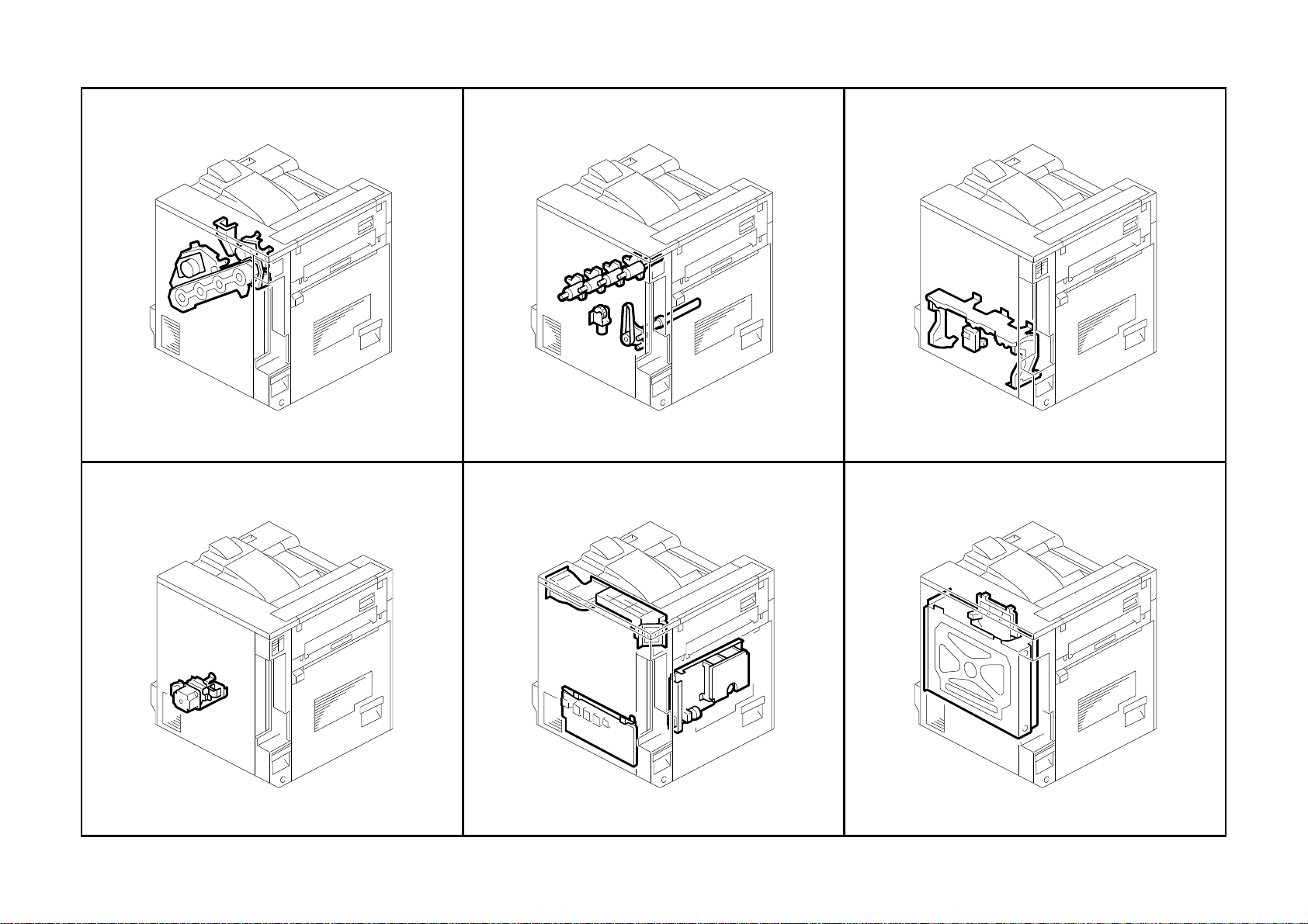
Page 62

21.Paper Exit Section 1 (G060)
G060 48 Parts Location and List
Page 63

21.Paper Exit Section 1 (G060)
Index
Index
No.
No.
1 G060 4430 Exit Cover 1
2 GA00 1004 Decal - Grip B2 1
3 AA12 0102 Discharge Brush - Exit 1
4 G060 4436 Compression Spring - Exit Driven 1
5 G060 4435 Bushing - M4 1
6 AF04 0586 Driven Roller 1
7 G060 4494 Exit Stay 1
8 AF04 0578 Exit Roller - FU 1
9 G060 4488 Upper Exit Guide 1
10 AF04 0582 Vertical Transport Roller - Exit 1
11 G060 4437 Exit Guide Plate 1
12 G060 4432 Rear Side Plate - Exit 1
13 AA08 2101 Bushing - 6x10x6 1
14 G060 4439 Timing Belt - S2M180 1
15 G060 4434 Pulley - 27T 1
16 AB01 2025 Gear & Pulley - 17Z/27Z 1
17 G060 4438 Pulley - 24T 1
18 G060 4440 Guide Plate - Lower Entrance Exit 1
19 G060 4442 Exit Gate Pawl 1
20 G060 4441 Link - Exit Gate Pawl 1
21 G060 4468 Entrance Guide - Paper Exit Unit 1
22 AF04 0579 Transport Roller - Fusing Exit 1
23 AF04 0584 Driven Roller - Fusing Exit 1
24 G060 4449 Bushing - M4 1
25 AF04 0585 Driven Roller - Relay 1
26 G060 4474 Magnet Catch 1
27 G060 4446 Upper Guide Plate - Fusing Exit 1
28 G060 4447 Driven Roller - M16 1
29 G060 4433 Front Side Plate - Exit 1
30 AA14 3716 Stepped Screw 1
31 G060 4429 Compression Spring - Exit Driven 1N 1
32 G060 4410 Paper Exit Unit 1
33 5215 2621 Snap Ring - M6 1
34 G060 4477 Cover - Duplex Lock 1
35 G060 4489 Compression Spring - 0.46N 1
Part No.
Part No.
Description
Description
Q’ty Per
Q’ty Per
Assembly
Assembly
Index
Index
No.
No.
36 G060 4496 Support Plate - Discharge Brush 1
101 0450 3008B Tapping Screw - M3x8
102 0720 0040E Retaining Ring - M4
103 0720 0030E Retaining Ring - M3
104 0353 0100B Screw - M3X10
105 0451 3008B Tapping Screw - M3x8
Part No.
Part No.
Description
Description
Q’ty Per
Q’ty Per
Assembly
Assembly
G060 49 Parts Location and List
Page 64

22.Paper Exit Section 2 (G060)
G060 50 Parts Location and List
Page 65

22.Paper Exit Section 2 (G060)
Index
No.
1 G060 4470 DC Solenoid - Gate Pawl 1
2 G077 5821 Guide Plate - Left Upper Rack 1
3 G060 6046 Rear Bracket - Option 1
4 G060 5513 Harness - Fusing AC 1
6 G060 6038 Detent Spring 2
7 G060 6033 Rear Holder Arm 1
8 G060 6035 Detent Roller 2
9 G060 6037 Detent Shaft 2
10 G060 6031 Bracket - Rear Lever 1
11 G060 6040 Cover - Fusing Unit Holder 1
12 GA00 1003 Decal - Grip B1 1
13 G060 6039 Grip - Cover 1
14 G060 6041 Bracket - Fusing Drawer 1
15 G060 6032 Bracket - Front Lever 1
16 G060 6036 Arm Shaft 1
17 G060 5822 Bracket - Safety Switch 1
18 G060 5823 Bracket - Door Switch 1
19 G060 5801 Bracket - Door Switch Lever 1
20 G060 5808 Arm - Safety Switch 1
21 G060 5804 Lever - Door Switch 1
22 G060 6045 Front Bracket - Option 1
23 AW02 0120 Photointerruptor - Flat 1
24 G060 6011 Slide Rail 2
25 G060 6021 Holder - Fusing Unit 1
26 G060 1078 Guide Rail - Fusing Unit 1
27 GA00 3029 Decal - Vertic al Tr ans port 1
28 G012 3897 Film - Toner End Sensor Harness 1
29 G060 6034 Front Holder Arm 1
Part No.
5 G060 1091 Rear Fusing Bracket 1
Description
Q’ty Per
Assembly
Index
No.
101 0720 0030E Retaining Ring - M3
102 0720 0060E Retaining Ring - M6
103 0451 3008H Tapping Screw - M3x8
104 0802 5276 Tapping Screw With Washer - M3x6
105 0451 3005B Tapping Screw - M3x5
106 0453 3006B Tapping Screw - M3x6
107 1105 0522 Edge Saddle - LES0510
108 1105 0511 Harness Clamp - LWS-0306ZC
Part No.
Description
Q’ty Per
Assembly
G060 51 Parts Location and List
Page 66

23.Paper Exit Section 3 (G060)
G060 52 Parts Location and List
Page 67

Q’ty Per
Index
Q’ty Per
Index
23.Paper Exit Section 3 (G060)
Q’ty Per
Index
Q’ty Per
Index
Rev. 09/26/2002
Part No.
No.
No.
1 G060 4098 Guide Shaft 12
2 A267 3255 Paper Separation Guide 12
3 AA14 3716 Stepped Screw 1
4 G060 4097 Roller Guide Holder 1
5 G060 5589 Socket - Oil Unit Detection Sensor 1
6 G060 4150 Bracket - Unit Reset Sensor 1
7 G060 1066 Upper Vertical Frame 1
8 G060 4467 Roller Holder 2
9 G060 4454 Driven Roller - M13 4
10 AA08 2101 Bushing - 6x10x6 3
11 G060 4457 Bracket - Exit Roller 1
12 AF04 0577 Exit Roller - FD 1
13 G060 4427 Lower Exit Guide Plate 1
14 G060 4460 Lever - Gate Pawl 1
15 G060 4461 Tension Spring - Gate Pawl 1
16 G060 4459 Gate Pawl 1
17 G060 4482 Feeler - Paper Sensor 1
18 G060 44 79 Shaft - Paper Sensor 1
19 AW02 0120 Photointerruptor - Flat 1
20 G060 4481 Bracket - Paper Sensor 1
21 G060 4451 Upper Exit Guide Plate 1
22 AA08 2102 Bushing - 6x10x6 1
23 G060 4330 DC Solenoid - On-Off 1
24 G060 4447 Driven Roller - M1 6 2
25 AF04 0583 Exit Transport Roller 1
26 AA12 0102 Discharge Brush - Exit 1
27 AW02 0121 Photointerruptor - Square 1
28 G060 4463 Timing Belt - S2M176 1
29 G060 4456 Gear - Z25/T30 1
30 G060 4458 Gear - 16Z 1
31 G060 4850 Stopper Shaft Bracket 1
32 G077 4464 Bracket - Gear 1
33 G077 4462 Gear - Z18/T27 1
34 G060 5504 Harness - Oil Unit Detection Sensor 1
35 G060 4335 Heat Sink - DC Solenoid Apply 1
Part No.
Description
Description
Assembly
Assembly
Part No.
No.
No.
36 G060 4428 Drive Roller - M13 2
37 G060 4095 Front Guide Holder 1
38 G060 4096 Rear Guide Holder 1
101 1105 0511 Harness Clamp - LWS-0306ZC
102 0450 3006B Tapping Screw - M3x6
103 0450 3008B Tapping Screw - M3x8
104 0720 0040E Retaining Ring - M4
105 0451 3006B Tapping Screw - M3x6
106 1105 0522 Edge Saddle - Les0510
107 0451 3010B Tapping Screw - M3x10
108 0353 0040B Screw - M3X4
109 0452 3008B Tapping Screw - M3x8
Part No.
Description
Description
Assembly
Assembly
G060 53 Parts Location and List
Page 68

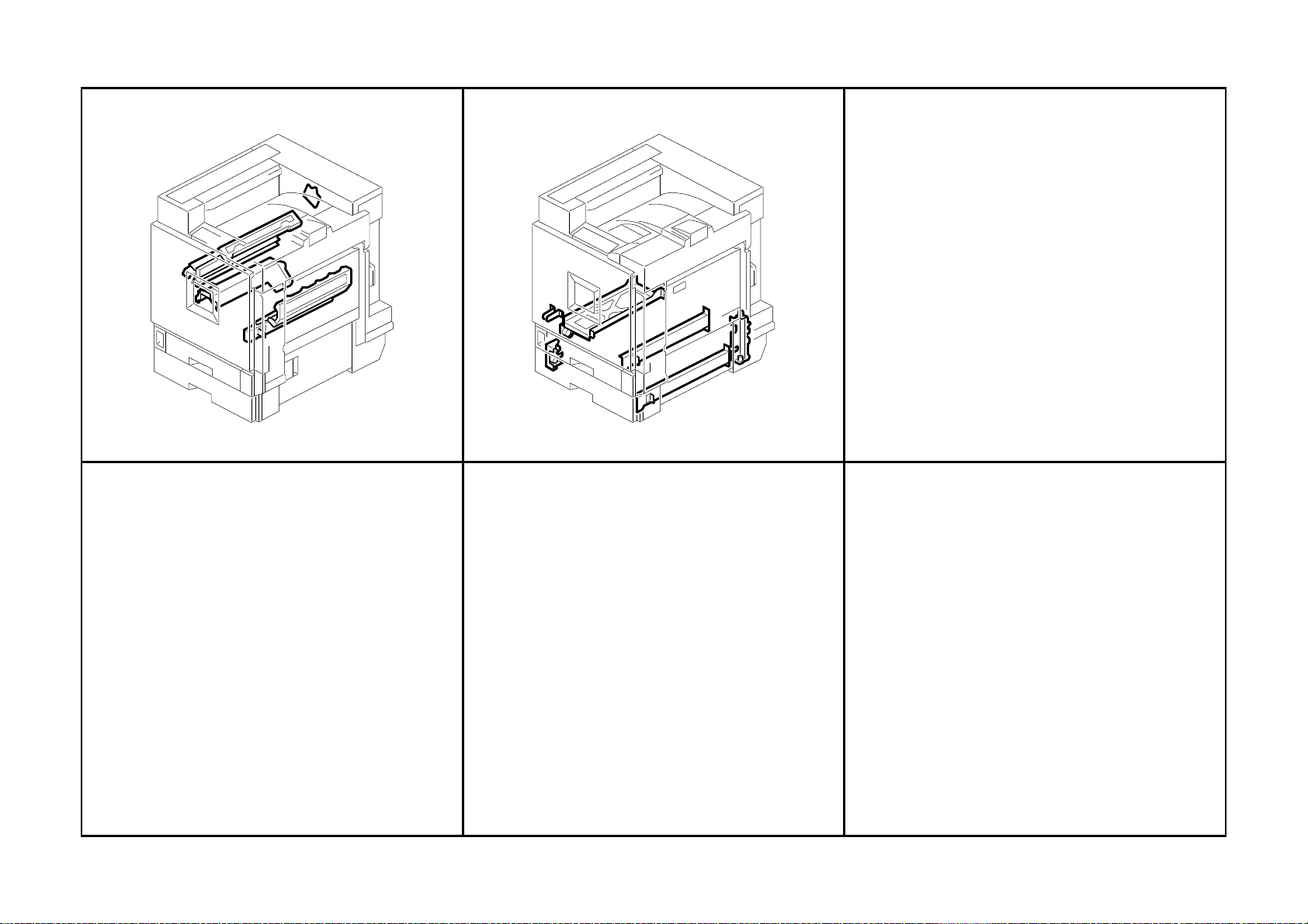
24.Waste Toner Transfer Section (G060)
G060 54 Parts Location and List
Page 69

Q’ty Per
Index
Q’ty Per
Index
24.Waste Toner Transfer Section (G060)
Rev. 09/26/2002
No.
1 G060 1072 PCU Guide Rail 1
2 G060 1184 Film - PCU Guide Rail 1
3 G060 1009 PCU Guide Rail - C/M/Y 3
4 G060 3372 Tube - K 1
5 G060 3603 Guide - Collection Bottle 1
6 G060 3384 Case - Y 1
7 G060 33 90 Case - C 1
8 G060 3371 Case - K 1
9 G060 3388 Case - M 1
10 G060 3350 Pump - K Toner Supply Unit 1
11 G060 3354 Pump - Y Toner Supply Unit 1
12 G060 3355 Pump - C Toner Supply Unit 1
13 G060 3352 Pump - M Toner Supply Unit 1
14 G060 1076 Left Guide - Development Unit 4
15 G060 1074 Upper Registration Stay 1
16 G060 2972 Safety Switch Feeler 1
17 G060 3385 Cover - Y 1
18 G060 3387 Cover - C 1
19 G060 3389 Cover - M 1
20 AA15 3471 Short Shield - CY 2
21 AA15 3464 Seal - Cover M/Y 3
22 G060 3289 Dual Faces Ttype Y - Long 1
23 G060 3288 Dual Faces Ttype Y - Short 1
24 G060 3290 Dual Faces Ttype C 1
25 AA15 3462 Seal - C/Y 2
26 AA15 3463 Seal - Case M/Y 6
27 AA15 3459 Seal - Case 1
Part No.
Description
Assembly
No.
101 0451 3006B Tapping Screw - M3x6
102 0451 3008B Tapping Screw - M3x8
Part No.
Description
Assembly
G060 55 Parts Location and List
Page 70

25.Drive Section 1 (G060)
G060 56 Parts Location and List
Page 71

25.Drive Section 1 (G060)
Index
No.
1 G060 1199 Inner PCU Duct 1
2 G060 1120 Drive Unit - C/M/Y Development 1
3 AA08 0257 Bushing - M6 4
4 G077 1100 Drive Unit - K Development 1
5 G077 1117 Magnetic Clutch Holder 4
6 AA08 2101 Bushing - 6x10x6 4
7 AX20 0244 Magnetic Clutch - Development 4
8 G060 1475 Joint - Development Unit 4
9 G077 1154 Bracket - Drum Drive 1
10 AB01 0113 Gear - Z180 4
11 G060 1473 Shielding Plate - Drum Gear 1
12 AB01 0110 Gear - Z63 1
13 AB01 0117 Gear - 60Z 1
14 AB01 1237 Gear - Z32/Z24 1
15 G077 1158 Transfer Drive Shaft 1
16 G077 1164 CMY Stepper Motor - DC3.25W 1
17 AA06 3622 Compression Spring 1
18 AA13 2211 Spacer - 8x0.5 2
19 AB01 7599 Gear - Z63/T28 1
20 G077 1163 Stepper Motor - DC3.25W 1
21 A232 3553 Ball Bearing - 8x16x5 1
22 G077 1153 Guide Plate - K Drum 1
23 AB01 1235 Gear - Z21 1
24 AB01 1231 Gear - Z18 1
25 G077 1166 Lower Sliding Plate 1
26 G077 1156 Fly Wheel - 165mm-M 1
27 G077 1168 Fly Wheel - CMY Stepper Motor 1
28 G077 1162 Fly Wheel - 98mm-C2 1
29 G077 1161 Fly Wheel - 84mm-C1 1
30 G077 1151 Fly Wheel - 140mm-K1 1
31 G077 1152 Fly Wheel - 140mm-K2 1
32 G060 6053 Grounding Plate - OPC Drum 4
33 AA13 2215 Spacer - 11mm 1
Part No.
Description
Q’ty Per
Assembly
Rev. 01/31/2003
Index
No.
101 0451 3006B Tapping Screw - M3x6
102 0451 3005B Tapping Screw - M3x5
103 0451 3008B Tapping Screw - M3x8
104 0805 0088 Retaining Ring - M6
105 0951 4008B Philips Screw With Washer - M4x8
106 1105 0511 Harness Clamp - LWS-0306ZC
107 1105 0487 Harness Clamp
108 0951 3014B Philips Screw With Washer - M3x14
109 0951 3016B Philips Screw With Washer - M3x16
110 0710 0030B Hexagon Nut - M3
111 0353 0160B Screw - M3x16
112 0574 0060E Hexagon Headless Set Screw – M4x6
113 0450 3008B Tapping Screw - M3x8
114 0805 0089 Retaining Ring - M4
Part No.
Description
Q’ty Per
Assembly
G060 57 Parts Location and List
Page 72

26.Drive Section 2 (G060)
G060 58 Parts Location and List
Page 73

26.Drive Section 2 (G060)
Index
No.
1 G077 1026 Drum Holder 1
2 G060 4855 Link Bracket 1
3 AW50 0023 Push Switch 1
4 G060 5530 Harness - Density Sensor 1
5 AA04 3928 Timing Belt - 40S2M334 1
6 5216 4198 Stepped Screw - Guide Plate 8
7 G060 5871 Clamp - M3.5 2
8 G077 3706 DC Motor - 1.56W 1
9 G077 3610 Joint - Collection Bottle 1
10 G060 5870 Clamp - M4.8 4
11 5447 2681 Snap Ring 1
Part No.
Description
Q’ty Per
Assembly
Rev. 04/25/2003
Index
No.
101 0451 3008B Tapping Screw - M3x8
102 0451 3006B Tapping Screw - M3x6
103 1105 0490 Harness Clamp - IWS-2218
104 1105 0489 Harness Clamp - LWS 1316
105 1105 0488 Harness Clamp
106 1105 0487 Harness Clamp
107 1105 0516 Clamp
108 1105 0511 Harness Clamp - LWS-0306ZC
109 1105 0522 Edge Saddle - LES0510
110 1102 8519 Connector - MI2 99RH139-9236
111 0451 3006H Tapping Screw - 3x6
Part No.
Description
Q’ty Per
Assembly
G060 59 Parts Location and List
Page 74
27.Drive Section 3 (G060)
G060 60 Parts Location and List
Page 75

27.Drive Section 3 (G060)
Index
No.
1 G060 1087 Rack Holder 1
2 AA06 0862 Tension Spring 1
3 G060 1106 Registration Tightener 1
4 5447 2681 Snap Ring 1
5 AB03 0686 Registration Timing Pulley 1
6 G060 1111 Relay Bracket 1
7 AB03 0685 Idle Pulley - M15 1
8 G060 2801 Holder - Paper Tray 2
9 G060 1085 Rear Right Channel 1
10 G060 2800 DC Motor - DC24V 0.5W 2
11 G060 5870 Clamp - M4.8 1
12 G060 4865 Duplex Right Bracket 1
13 G060 1053 Drawer Bracket - Paper Feed Table 1
14 G060 1083 Rear Left Channel 1
15 AW50 0023 Push Switch 3
Part No.
Description
Q’ty Per
Assembly
Index
No.
101 0451 3006B Tapping Screw - M3x6
102 0802 5276 Tapping Screw With Washer - M3x6
103 1102 8534 Connector - QR/P17-14S-B
104 1105 0489 Harness Clamp - LWS 1316
105 1105 0518 Edge Saddle - LES-1010
106 1105 0521 Clamp - LES-1017
107 1105 0487 Harness Clamp
108 1105 0488 Harness Clamp
109 1105 0511 Harness Clamp - LWS-0306ZC
110 1102 8537 Connector - QR/P17-18P-A
111 1102 8535 Connector - QR/P17-14P-A
Part No.
Description
Q’ty Per
Assembly
G060 61 Parts Location and List
Page 76

28.Drive Section 4 (G060)
G060 62 Parts Location and List
Page 77

Q’ty Per
Index
Q’ty Per
Index
28.Drive Section 4 (G060)
Rev. 09/26/2002
No.
1 AX20 0220 Magnetic Clutch - Registration 1
2 5215 2621 Snap Ring - M6 1
3 AA04 3561 Timing Belt - 40S3M318 1
4 AB01 7546 Gear - Z28/T35 1
5 AB03 0690 Timing Pulley - T20 1
6 AB01 7543 Gear - Z25/T26 1
7 AA04 3925 Timing Belt - S2M668 1
8 G060 1172 Tightener - Paper Feed 1 1
9 AA06 0863 Tension Spring 2
10 AB01 7597 Gear - 13Z 1
11 AB01 2310 Gear - Z19 1
12 G060 2765 Paper Feed Bracket 1
13 AB01 7545 Gear - Z28/Z21 1
14 G077 1172 Paper Feed Motor Unit - DC4.42W 1
15 AB01 7544 Gear - Z25/T20 2
16 AA16 11 53 Motor Cushion 1
17 G060 1169 Separation Plate - Paper Feed Dri ve 1
18 AB01 7542 Gear - 15Z/30Z 1
19 AA04 3563 Timing Belt - 40S3M162 1
20 G060 1177 Bracket - Magnetic Clutch 2 1
21 G077 1171 Bracket - Paper Feed Drive 1
22 G060 1176 Bracket - Magnetic Clutch 1 1
23 AB03 0710 Timing Pulley - 20T 1
24 AA04 3562 Timing Belt - 40S3M384 1
25 AA08 2102 Bushing - 6x10x6 2
26 AX20 0221 Magnetic Clutch - Paper Feed 2
27 AB01 4037 Gear - 24Z 2
28 AB01 4038 Gear - 22Z 2
29 G060 1174 Tightener - Paper Feed 1
30 AW02 0120 Photointerruptor - Flat 4
31 AB01 7540 Gear - Z28/Z29 1
32 G060 2897 Positioning Plate - Bypass 1
Part No.
Description
Assembly
No.
101 0451 3006B Tapping Screw - M3x6
102 0451 4008B Philips Tapping Screw - M4x8
103 0314 0100B Philips Pan Head Screw - M4x10
104 0720 0040E Retaining Ring - M4
105 1105 0488 Harness Clamp
106 1105 0511 Harness Clamp - LWS-0306ZC
107 1105 0487 Harness Clamp
108 1105 0489 Harness Clamp - LWS 1316
Part No.
Description
Assembly
G060 63 Parts Location and List
Page 78
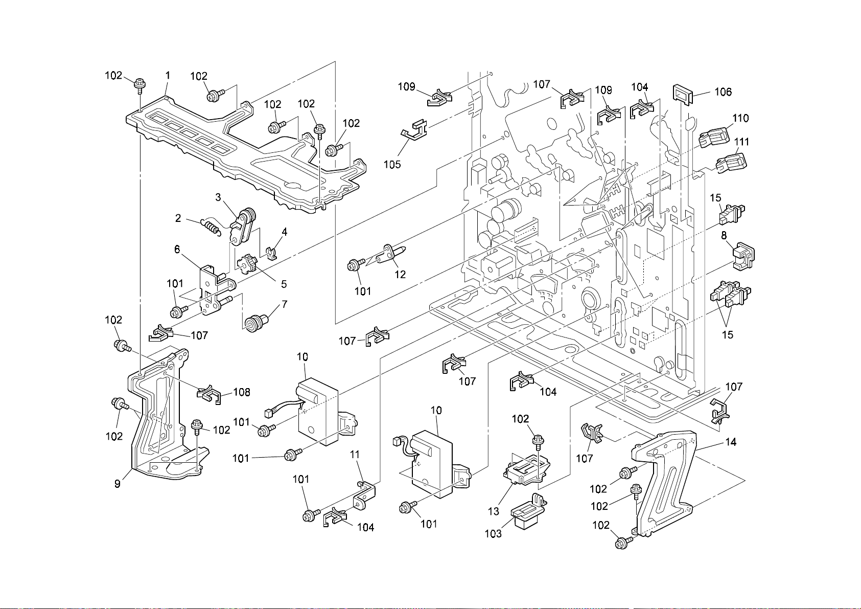
29.Electrical Section 1 (G060)
G060 64 Parts Location and List
Page 79

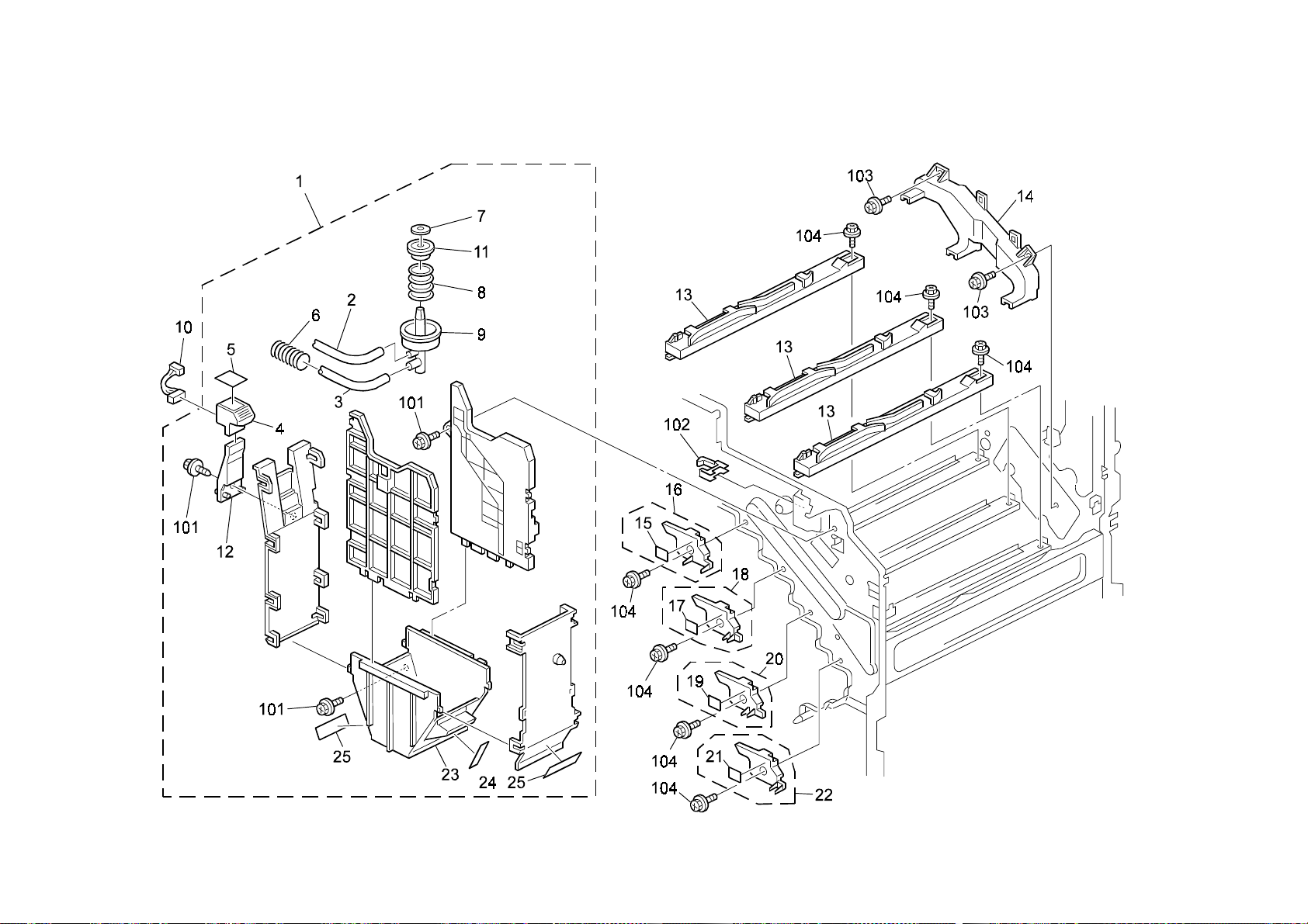
29.Electrical Section 1 (G060)
Index
No.
1 G077 5820 Guide Plate - Upper Rack 1
2 G060 1192 Right Upper Rear Guide 1
3 G060 1189 Upper PSU Duct 1
4 AX64 0103 Fan Motor - DC2.4W 1
5 G060 1557 Duct - DC Motor Guard 1
6 G060 1182 Duct - Fan 1
7 G060 1555 Upper Controller Duct 1
8 AX64 0123 Fan Motor - DC1.68W 2
9 G077 1556 Lower Controller Duct 1
10 G077 5510 Harness - Power Pack CB 1
11 GZ32 0009 Power Pack - CB 1
12 G060 5816 Bracket - Power Pack 1
13 G060 5862 Cap - PSU 5
14 G060 5866 PSU Cover 1
15 AA06 3613 Compression Spring 1
16 G060 5861 Inner Back Lever - Door Switch 1
17 AA06 3638 Compression Spring 1
18 GZ23 0017 Power Supply Unit - 120V 1
18 GZ23 0018 Power Supply Unit - 220V 1
19 G060 5513 Harness - Fusing AC 1
20 G060 5516 Harness - AC Switch 1
21 G060 5863 Bracket - PSU Fan 1
22 G077 1195 Duct - FFC Spacer 1
Part No.
Description
Q’ty Per
Assembly
Rev. 10/31/2003
Index
No.
101 0451 3006B Tapping Screw - M3x6
102 0802 5276 Tapping Screw With Washer - M3x6
103 0954 3008B Philips Screw - M3x8
104 1105 0516 Clamp
105 0801 0150 Philips Screw - M4x8
106 1105 0522 Edge Saddle - LES0510
107 1105 0511 Harness Clamp - LWS-0306ZC
108 0802 5286 Tapping Screw
109 0450 4035B Philips Tapping Screw - M4x35
110 1102 6246 Relay Connector - 4P
111 1150 0363 Power Supply Code - 125V 10A 2.5M
111 1150 0364 Power Supply Code- 250V 10A 2.5M
112 1107 0629 Fuse (ceramic Case) - 15A- 125V
113 1107 0879 Fuse - 5A 250V
113 1107 0908 Fuse - 10A 125V
Part No.
Description
Q’ty Per
Assembly
G060 65 Parts Location and List
Page 80

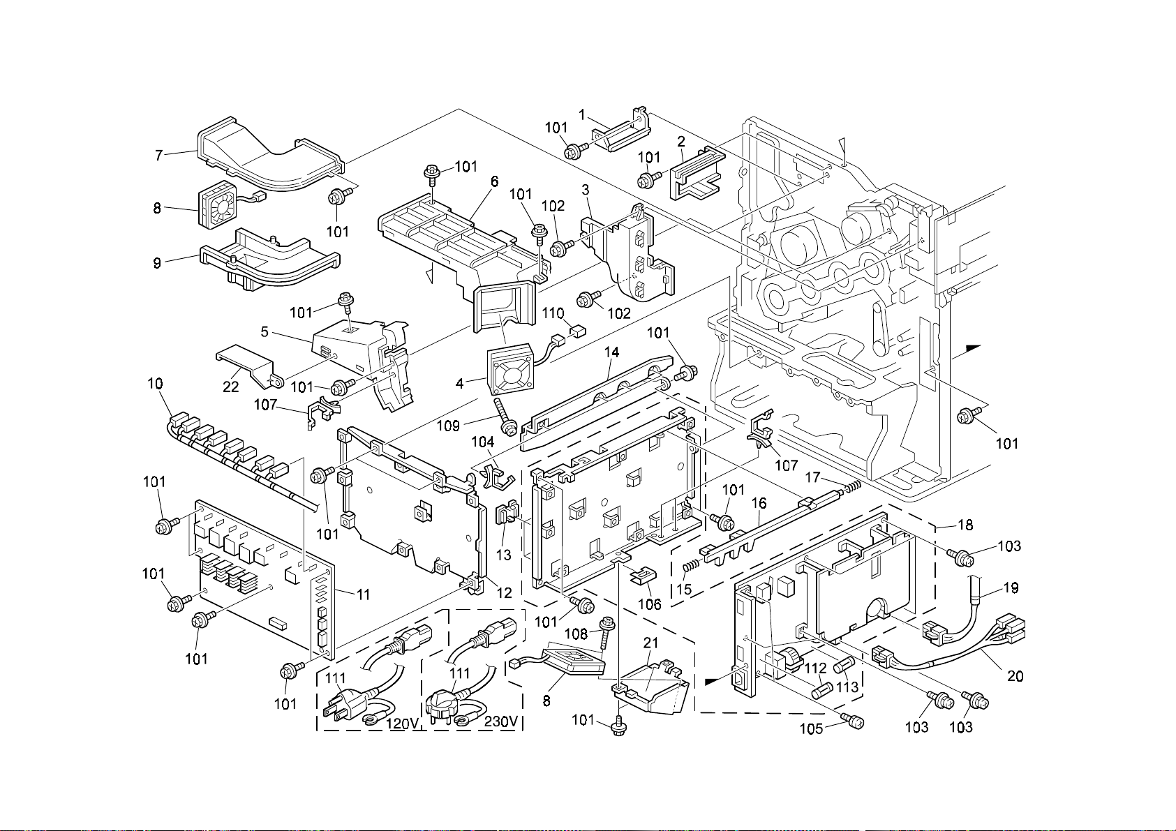
30.Electrical Section 2 (G060)
G060 66 Parts Location and List
Page 81

Q’ty Per
Index
Q’ty Per
Index
30.Electrical Section 2 (G060)
Rev. 07/29/2003
No.
1 G077 61 21 ROM DIMM - PDL 1
2 G060 5847 Rack - Inner Back Application 1
3 G060 5740 Controller Board 1
4 G034 2993 Flanged Hexagonal Head Bolt - M3x6 6
5 G060 5853 Grip - Application 1
6 G060 5854 Panel Cover - Option 3
7 G060 5852 Panel - Control Board 1
8 G060 5856 Bracket - Controller Board 1
9 G077 5454 Harness - PSU 1
10 G077 5500 Harness - Dev Motor K 1
11 G077 1194 Cover - Fan Duct 1
12 G077 5841 Application Rack Assy 1
13 G077 5848 Bracket - Harness 1
14 G060 5849 Left Rear Cover 1
15 G077 5451 Harness - Middle Main 1
16 G077 5455 Harness - Fusing DC 1
17 G077 5452 Harness - Left Main 1
18 G077 5061 J-BCU Board 1
19 G077 5450 Harness - Lower Main 1
20 G060 5829 Upper Spring Plate - Rack 1
Part No.
Description
Assembly
No.
101 0353 0060B Philips Pan Head Screw - M3x6
102 0353 0060Z Screw - M3X6
103 0451 3006B Tapping Screw - M3x6
104 1105 0367 Spacer
105 1105 0489 Harness Clamp - LWS 1316
106 1105 0490 Harness Clamp - IWS-2218
107 1105 0487 Harness Clamp
Part No.
Description
Assembly
G060 67 Parts Location and List
Page 82

31.Frame Section 1 (G060)
G060 68 Parts Location and List
Page 83

31.Frame Section 1 (G060)
Index
No.
1 G060 4820 Relay Guide Plate 1
2 G060 3650 Left Slide Rail 1
3 G060 1068 Left Guide Plate - Imaging Unit 1
4 AW02 0121 Photointerruptor - Square 1
5 G060 3623 Collection Bottle Bracket 1
6 AW50 0025 Set Sensor - Collection Bottle 1
7 G060 3661 Right Slide Rail 1
8 G060 1070 Right Guide Plate - Imaging Unit 1
9 G060 4860 Duplex Left Bracket 1
10 G060 5898 FCC Harness Cushion 1
11 G060 5899 FFC Harness Plate 1
12 G060 5493 Harness - Bottle Set Sensor 1
13 G060 4130 Oil Pad 1
Part No.
Description
Q’ty Per
Assembly
Index
No.
101 0451 3006B Tapping Screw - M3x6
102 0451 3010B Tapping Screw - M3x10
103 1105 0511 Harness Clamp - LWS-0306ZC
104 1105 0487 Harness Clamp
Part No.
Description
Q’ty Per
Assembly
G060 69 Parts Location and List
Page 84
32.Frame Section 2 (G060)
G060 70 Parts Location and List
Page 85

32.Frame Section 2 (G060)
Index
No.
1 G060 1079 Holder - Used Collection Bottle 1
2 G012 4617 Stepped Screw - M3 1
3 G060 2779 Left Supporter 1
4 G060 1089 Front Left Supporting Plate 1
5 G060 1277 Bracket - Front Cover Hinge 1
6 G060 1081 Shielding Plate - Paper Feed 1
7 G060 2780 Right Supporter 1
8 5447 2681 Snap Ring 1
9 G060 2834 Lower Positio nin g Pla te 1
10 G060 2830 Upper Positioning Plate 1
11 G060 1095 Vertical Transport Hinge 1
12 G060 5487 Harness - On-Off Sensor Right 1
13 AW02 0120 Photointerruptor - Flat 2
14 G060 3998 Seal - Sensor 1
15 G060 5491 Harness - On-Off Sensor Left 1
16 G060 3626 Used Toner Sensor Spring 1
17 G060 3627 Toner Bottle Sensor Feeler 1
18 AA00 0401 Decal - High Temperature 1
19 AX40 0109 Heater - 120V 9W 1
19 AX40 0110 Heater - 230V 9W 1
20 A134 2947 Heater Cover 1
21 GA00 3037 Decal - Power Sour ce 1
22 G060 5519 Harness - Heater 1
23 B004 2995 Cap - Positioning 1
Part No.
Description
Q’ty Per
Assembly
Index
No.
101 0451 3006B Tapping Screw - M3x6
102 0802 5276 Tapping Screw With Washer - M3x6
103 1105 0522 Edge Saddle - LES0510
104 0360 4006B Hexagonal Head Screw - M4x6
105 1105 0487 Harness Clamp
Part No.
Description
Q’ty Per
Assembly
G060 71 Parts Location and List
Page 86

33.Printer Control Board (G060)
G060 72 Parts Location and List
Page 87

33.Printer Control Board (G060)
G060 73 Parts Location and List
Page 88

33.Printer Control Board (G060)
G060 74 Parts Location and List
Page 89

33.Printer Control Board (G060)
G060 75 Parts Location and List
Page 90

Page 91

33.Printer Control Board (G060)
G060 75A Parts Location and List
Page 92

33.Printer Control Board (G060)
G060 76 Parts Location and List
Page 93

33.Printer Control Board (G060)
Index
No.
* G060 5740 Controller Board 1
* G060 9099 Total Counter - RAM-STK12C68-P55 1
1 G060 5785 IC-ASIC COMIC 1
2 G060 5980 Heat Sinker 1
3 G060 5982 Heat Sinker - PUG16 1
Part No.
Description
Q’ty Per
Assembly
Index
No.
101 1102 2391 Connector - HIF3FB-40PA-2.54DSA
102 1102 5303 Connector - 4P
103 1102 7785 Connector - 57RE40360830BD29B
104 1102 8153 Connector - FCN-568P068-G/05A-V4
105 1102 8355 Connector - Dimm - DMM2-SD72A-1131
106 1102 8357 Connector - 52777-0809
107 1102 8373 Connector - RJHS-5381
108 1102 8516 Connector - DIMM-20-6403-144-121-856
109 1102 8582 Connector - IMSA-9730B-200A-GF
110 1102 8583 Connector - 440024-1
111 1102 8584 Connector - 52777-0409
112 1104 0511 IC Socket - 8P - DICF-8CS-E
113 1104 0771 IC Socket - 28PIN
114 1204 1422 Dip Switch - 51d-0401
115 1400 0891 Transistor - RT1N136C
116 1402 1336 Diode - 1SS355
117 1402 1343 Diode - RB106L-40
118 1407 4919 IC - 74VHCT244 TSSOP
119 1407 5122 IC - CMOS LOGIC-TC74ACT374FT
120 1407 5275 CMOS Logic - 74LVCHR16245A TSSOP
121 1407 5281 IC - EEPROM-I2C BUS 1K SOP
122 1407 5282 IC - DP83846AVHG
123 1407 5674 IC - DP83846AVHG
124 1407 5297 IC - CPU RM7000-250T-REV2.1E
125 1407 5300 CMOS Logic - 74LVC16244A TSSOP
126 1407 5309 IC - MICROWIRE BUS 1K DIP
127 1407 5320 CMOS Logic 74LVC374A TSSOP
128 1407 5321 CMOS Logic - 74LVCH16374A TSSOP
129 1407 5322 IC - CMOS LOGIC SN74LVC161284DGG
130 1407 5329 Clock Generator - W211b
131 1407 5334 IC - CMOS LOGIC 74LVC244A TSSOP
132 1408 0575 IC - M51957BFP
133 1408 1507 Regulator - PQ05VY3H3Z
134 1408 1561 Series Regulator - Q5EV3
135 1503 0842 Oscillator - 14.31818MHz
Part No.
Description
Q’ty Per
Assembly
G060 76A Parts Location and List
Page 94

Page 95

Index
No.
136 1503 0959 Crystal Oscillator - 25MHz
137 1601 7752 Resistor Array - 10K Ω ±5%
138 1601 7760 Resistor Array
139 1601 7781 Resistor - 10 Ω ±5%
140 1601 7867 Resistor - 33 Ω ±5% 1/16W
141 1601 7871 Resistor - 68Ω ±5% 1/16W
142 1601 7872 Resistor Array - 220 Ω ±5% 1/16W
143 1601 7879 Resistor - 22 Ω ±5% 1/16W
144 1601 7915 Resistor Array - 33 Ω ±5% 1/16W
145 1601 7933 Resistor Array - 100 Ω ±5% 1/16W
146 1604 4333 Capacitor - 100µF±20% 10V
147 1604 4365 Condenser - 470µF16v ±20%
148 1605 1025 Capacitor - 1000pF ±10% 2KV
149 1605 1071 Capacitor - 1µF±10% 25V
150 1605 1072 Capacitor - 4.7µF±10% 16V
151 1605 1081 Capacitor - 10 µF+80-20% 25V
152 1605 1085 Ceramic Capacitor - 0.082µF±10% 1
153 1605 1127 Capacitor - 8±0.5pF 50V
154 1605 1162 Capacitor - 10µF+80 -20% 10V
155 1607 0824 Filter - BLM11A601SPB
156 1607 0987 Inductor - TLA-6T103
157 1607 1206 Filter - ACC2012L-250
158 1630 2271 Resistor - 270Ω - 1/8W
159 1630 2750 Resistor - 758Ω 1/8W ±5%
160 1630 3271 Resistor - 270 Ω +5% 1/10W
161 1630 3519 Resistor - 5.1 Ω ±5% 1/10W
162 1630 3561 Resistor - 560 Ω ±5% 1/10W
163 1630 4103 Resistor - 10KΩ ±5% 1/16W
164 1630 4122 Resistor - 1.2K Ω 5% 1/16W
165 1630 4150 Resistor - 15Ω ±5.00%,1/16W
166 1630 4184 Resistor - 180k Ω ±5% 1/16W
167 1630 4220 Resistor - 22 Ω ±5% 1/16W
168 1630 4222 Resistor - 2.2K Ω ±5%
169 1630 4330 Resistor - 33 Ω ±5% 1/8W
170 1630 4470 Resistor - 470 Ω ±5% 1/16W
Part No.
Description
Q’ty Per
Assembly
Index
No.
171 1630 4472 Resistor - 4.7KΩ ±5% 1/16W
172 1630 4512 Resistor - 5.1k Ω - ±5% - 1/16W
173 1630 4680 Resistor - 68 Ω ±5% 1/16W
174 1630 4681 Resistor - 680 Ω ±5% 1/16W
175 1630 4753 Resistor - 75K Ω ±5% 1/16W
176 1632 0000 Resistor - 0 Ω 1/8W
177 1632 4999 Resistor - 49.9Ω ±1% 1/8W
178 1632 5499 Resistor - 54.9 Ω ±1% 1/8W
179 1634 0000 Resistor - 0 Ω 1/16W
180 1634 1001 Resistor - 1KΩ ±5% 1/16W
181 1634 1201 Resistor - 1.2K Ω ±1% 1/16W
182 1634 1501 Resistor - 1.50k Ω ±1% 1/16W
183 1634 1621 Resistor - 1.62KΩ ±1% 1/16W
184 1634 2001 Resistor - 2.00K Ω ±1% 1/16W
185 1634 9311 Resistor - 9.31KΩ ±1% 1/16W
186 1644 0470 Capacitor - 47µF±20% 10V
187 1644 6101 Capacitor - 100µF±20% 6.3V
188 1660 0100 Capacitor - 10PF ±0.5pF 50V
189 1660 2150 Capacitor - 15pF ±5% 50V
190 1660 2220 Capacitor - 22pF ±20% 35V
191 1660 2221 Capacitor - 220pF +80-20% 50V
192 1660 2330 Capacitor - 33pF - ±5% - 50V
193 1660 2471 Capacitor - 470pF - ±5% - 50V
194 1660 4102 Capacitor - 1000pF ±10% 50V
195 1660 6103 Capacitor - 10000pF - +80%-20%50V
196 1660 8104 Capacitor - 0.1µF+80-20% 25V
197 1906 0016 IC - LH28F160BJE-BTL70
198 1102 7615 Connector - B8B-XH-A
199 1407 2187 TTLIC - SN74LS07NS
200 1601 7833 Resistor Array - 330Ω ±5% 1/16W
201 1650 4620 Resistor - 62Ω ±5% 1/10W
202 G060 9099 Total Counter - RAM-STK12C68-P55
Part No.
Description
Rev. 03/17/2003
Q’ty Per
Assembly
G060 77 Parts Location and List
Page 96
34.BCU Board (G060)
G060 78 Parts Location and List
Page 97

34.BCU Board (G060)
G060 79 Parts Location and List
Page 98

34.BCU Board (G060)
G060 80 Parts Location and List
Page 99

34.BCU Board (G060)
G060 81 Parts Location and List
Page 100

34.BCU Board (G060)
G060 82 Parts Location and List
 Loading...