

Page 1

FRESA WIN+
(Machine Code: G047/G048)
SERVICE MANUAL
[Controller]
Page 2

IMPORTANT SAFETY NOTICES
PHYSICAL INJURY PREVENTION
1. Before disassembling or assembling parts of the printer and peripherals,
make sure that the power cord is unplugged.
2. The wall outlet should be near the printer and easily accessible.
3. Note that some printer components are supplied with electrical voltage even
if the main switch is turned off.
4. If an adjustment or operation check must be made requiring the removal or
opening of the exterior covers while the main switch is on, keep hands away
from electrified or mechanically driven components.
5. The printer drives some of its components when it completes the warm-up
period. Keep hands away from mechanical and electrical components when
the printer starts operation.
6. The interior and metal parts for the fusing unit become extremely hot while
the printer is operating. Do NOT touch these components with bare hands.
HEALTH SAFETY CONDITIONS
1. Never operate the printer without ozone filters installed.
2. Always replace the ozone filters with the specified replacement at the
specified maintenance intervals.
3. Toner is non-toxic, but if it gets in your eyes by accident, it may cause
temporary eye discomfort. Remove it with eye drops or flush eyes with
water. If this is unsuccessful, get medical attention immediately.
SAFETY AND ECOLOGICAL NOTES FOR DISPOSAL
1. Do NOT incinerate toner cartridges, development toner magazine (DTM) or
used toner. Toner dust may ignite suddenly when exposed to an open flame.
2. Dispose of used toner bottle and photoconductor unit (PCU) in accordance
with local regulations. (These are non-toxic supplies.)
3. Dispose of replaced parts in accordance with local regulations.
Page 3

Trademarks
Microsoft, Windows 98/95/3.1x, and Windows NT 4.0 are registered trademarks of
Microsoft Corporation.
Macintosh and AppleTalk are registered trademarks of Apple Computer, Inc.
NetWare is a registered trademark of Novell, Inc.
Ethernet is a registered trademark of Xerox Corporation.
General Notice:
Other product names used herein are for identification purposes only and may be
trademarks of their respective companies. We disclaim any and all rights in those
marks.
Page 4

TABLE OF CONTENTS
1. OVERALL MACHINE INFORMATION....................................... 1-1
1.1 BASIC SPECIFICATIONS.........................................................................1-1
2. DETAILED DESCRIPTIONS....................................................... 2-1
2.1 DIFFERENT POINT FROM BASE MODEL (G024)...................................2-1
2.1.1 SYSTEM SOFTWARE......................................................................2-1
2.1.2 HARDWARE.....................................................................................2-1
2.2 FUNCTIONAL OVERVIEW.......................................................................2-2
2.2.1 SYSTEM LAYOUT............................................................................2-2
2.2.2 CONTROLLER BOARD LAYOUT....................................................2-3
2.2.3 FUNCTION OF EACH DEVICE........................................................2-4
2.3 PRINT DATA PROCESSING....................................................................2-5
2.3.1 GRADATION & PRINTABLE DATA..................................................2-5
2.3.2 IMAGE DATA PROCESSING FLOW ...............................................2-6
IPDL-C (Intelligent Page Description Language for Color)....................2-7
CMS (Color Management System).......................................................2-8
Color Correction by the Driver ..............................................................2-8
BG/UCR (Black Generation/Under Color Removal)..............................2-8
Gamma Correction ...............................................................................2-8
Dither Processing .................................................................................2-9
Maximum Amount Toner Control..........................................................2-9
4 Bit Expansion.....................................................................................2-9
3. INSTALLA T ION.......................................................................... 3-1
4. SERVICE TABLES...................................................................... 4-1
4.1 CONTROLLER SP MODE ........................................................................4-1
4.1.1 ENTERING AND EXITING CONTROLLER SP MODE....................4-1
4.1.2 MENUS AND DISPLAY.................................................................... 4-2
4.1.3 SP MODE MENU HIERARCHY........................................................4-2
4.1.4 SP MODE DETAILS.........................................................................4-6
S1. Maintenance Sheet.........................................................................4-6
S2. Color Chart.....................................................................................4-7
S3. Maintenance Clear.........................................................................4-7
S4. Clear All Memory............................................................................4-7
S5. Gamma (γ) Calibration....................................................................4-7
S6. Printer ID........................................................................................4-7
S7. Toner Limiter..................................................................................4-8
S8. Brand (Default Setting: RICOH.EXP) .............................................4-8
S9. Meter Click .....................................................................................4-8
IPDL-C Menu........................................................................................4-9
Media Menu ([Media] key) ....................................................................4-9
i
Page 5

4.2 POWER-UP SELF-DIAGNOSTICS.........................................................4-10
4.3 POWER-UP SELF-DIAGNOSTICS FLOW CHART................................4-10
4.4 DETAILED SELF-DIAGNOSTICS MODE ...............................................4-11
4.5 DETAILED SELF-DIAGNOSTICS FLOW CHART...................................4-11
5. PERIODIC MAINTENANCE........................................................ 5-1
6. REPLACEMENT AND ADJUSTMENT........................................ 6-1
6.1 CONTROLLER BOARD REPLACEMENT ................................................6-1
6.2 IMAGE ADJUSTMENT..............................................................................6-1
6.3 SOFTWARE UPGRADE PROCEDURE....................................................6-1
7. TROUBLESHOOTING ................................................................ 7-1
7.1 TYPES OF PROBLEMS............................................................................7-1
7.2 TROUBLESHOOTING PROCEDURE.......................................................7-2
7.2.1 HARDWARE TESTS........................................................................7-2
7.2.2 OPERATION-RELATED TESTS......................................................7-2
7.2.3 SOFTWARE-RELATED TESTS.......................................................7-2
7.3 ERROR MESSAGES ................................................................................7-3
7.3.1 OVERVIEW......................................................................................7-3
7.3.2 CONTROLLER SELF-DIAGNOSTICS ERRORS.............................7-4
7.3.3 CONTROLLER USER ERRORS......................................................7-5
7.3.4 INTERNAL ERRORS........................................................................7-6
7.3.5 ENGINE USER ERRORS (CAUTIONARY)......................................7-7
7.3.6 ENGINE USER ERRORS.................................................................7-7
7.3.7 ENGINE SERVICE CODES .............................................................7-7
8. NETWORK INTERFACE BOARD (C4000 FERRET).................. 8-1
8.1 OVERVIEW...............................................................................................8-1
8.1.1 SPECIFICATIONS............................................................................8-1
8.1.2 BLOCK DIAGRAM............................................................................8-1
8.2 COMPONENT LAYOUT............................................................................8-2
8.2.1 NETWORK INTERFACE BOARD DIAGRAM...................................8-2
8.2.2 DEVICES..........................................................................................8-2
8.3 BASIC OPERATIONS...............................................................................8-3
8.3.1 OVERVIEW......................................................................................8-3
8.3.2 SWITCH FUNCTION........................................................................8-4
NVRAM Reset Procedure.....................................................................8-4
ii
Page 6

30 June 2000 OVERALL MACHINE INFORMATION
1. OVERALL MACHINE INFORMATION
1.1 BASIC SPECIFICATIONS
Page Description
Language:
Printer Driver:
Resolution: 600 dpi
Color Mode: Color, B&W
Gradation Mode 1 or 2 bits/pixel
Toner Saving: On/Off (printer driver setting) Default Setting: Disabled
Color Correction: On/Off (printer driver setting) Default setting: Enabled
Interface:
Fonts Ricoh-Script 2: 39 Roman fonts
Memory Standard: 32 MB (simplex model), 64 MB (duplex model),
• IPDL-C (Intelligent Page Description Language for Color)
• Ricoh-Script 2
• IPDL-C: Windows 95/98/2000/NT 4.0
• Ricoh-Script 2: Windows 95/98/2000/NT 4.0, Macintosh
(PPD for LaserWriter 8)
• Standard: Parallel port (IEEE1284: Compatible/Nibble/
ECP mode supported)
• Option: Parallel port (IEEE1284: only Compatible mode
supported), Ethernet (100 BASE-TX, 10 BASE-T)
(It can be replaced with optional memory.)
Overall
Information
Up to 256 MB (Replace the standard memory with optional
128-MB memory SDRAMS.)
SDRAM DIMM Slot 2 (for optional memory)
Option Bus Interface 2 (for optional network I/F board and optional parallel I/F)
Options
• 32 MB Memory
• 64 MB Memory
• 128 MB Memory
• Network Interface Board
• IEEE1284 Parallel Interface
1-1
Page 7

30 June 2000 DETAILED DESCRIPTIONS
2. DETAILED DESCRIPTIONS
2.1 DIFFERENT POINT FROM BASE MODEL (G024)
2.1.1 SYSTEM SOFTWARE
1. Automatic duplex printing is available for the duplex model.
2. Manual duplex printing (printing on the reverse side) is available for the simplex
model.
3. The appropriate electric counter can be selected depending on the type of
maintenance contract for meter click charge. A new User mode, “Show
Counter”, has been added to display the Color and B/W counter values.
4. If the printer driver has been installed, the printer keeps a record of the number
of pages printed out under each registered User Code (Up to 100).
5. This printer has a job log which shows the time, number of pages and current
status of each print job. Up to 64 User IDs (User Codes) can be set.
6. The bypass tray can be used as a manual tray. If it is set to “Manual”, the paper
size selected by the printer driver takes priority over the size selected on the
operation panel.
Detailed
Descriptions
7. The printer can be set so that it will either stop or continue printing when toner
has run out.
8. 300-dpi mode is not supported.
9. It is possible to enter SP mode without turning the machine off and on.
10. The optional network interface board (C4000 Ferret) supports PortNavi.
2.1.2 HARDWARE
1. CPU
NEC VR4310-177
2. ASIC
Rocky-R, which is compatible with SDRAM. FCI2.5C was removed because
300-dpi mode is not supported. Therefore, toner saving mode is controlled by
firmware.
3. SDRAM
The type of SDRAM used has been changed from SIMM to DIMM.
4. NVRAM
The capacity of the NVRAM has been expanded to 8 KB to store the Job and
Print Logs.
5. DIP Switches
Dip switches do not require resetting when upgrading firmware.
2-1
Page 8
DETAILED DESCRIPTIONS 30 June 2000
2.2 FUNCTIONAL OVERVIEW
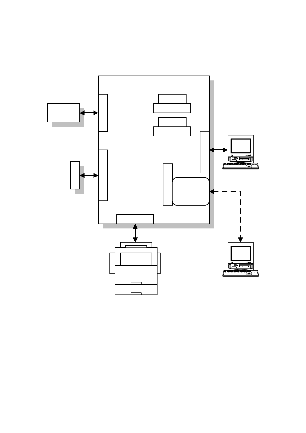
2.2.1 SYSTEM LAYOUT
Controller Board
SDRAM
IC Card
RPS2
IC Card I/F
Program ROM I/F
Video I/F
SDRAM I/F
SDRAM
SDRAM I/F
IEEE1284 I/F
Host
Network I/F
Board
Option Bus I/F
2-2
Host
G048O701.WMF
Page 9
30 June 2000 DETAILED DESCRIPTIONS
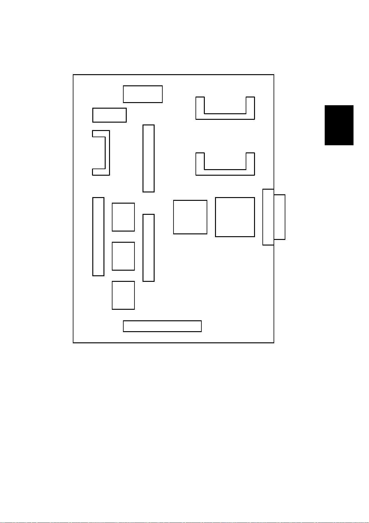
2.2.2 CONTROLLER BOARD LAYOUT
NVRAM
DIP SW
Option RAM I/F
IC Card I/F
Option RAM I/F
Detailed
Descriptions
ROM
Flash
Program ROM I/F
ROM
Flash
Font
ROM
Option Bus I/F Option Bus I/F
Video I/F
CPU
R4310
ASIC
ROCKY R
IEEE1284 I/F
G048O702.WMF
2-3
Page 10
DETAILED DESCRIPTIONS 30 June 2000
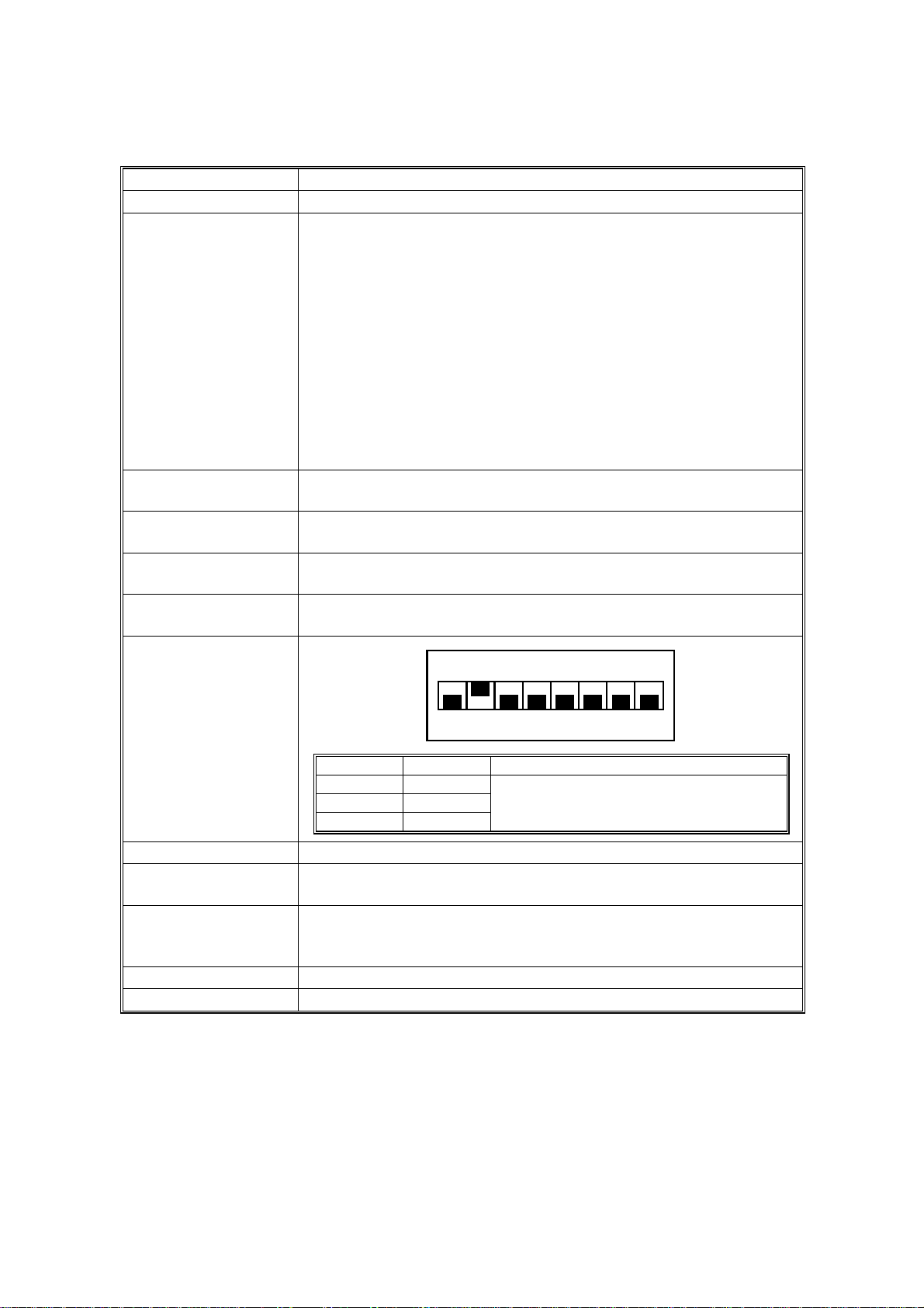
2.2.3 FUNCTION OF E ACH DEVICE
Device Function
CPU VR4310-177 (177 MHz)
ASIC ROCKY R This ASIC controls the following:
• Memory mapping
• Reset
• DRAM
• Data r eceived from the parallel
• Video DMA
• PvDMA
• Interrupt
• Serial communication with engine
• IEEE1284 interface
• Timer
•
I/O Port
FLASH ROM Stores program (2 MB) The flash ROM is programmable via an
IC card.
NVRAM
FONT ROM Stores internal printer fonts.
Program ROM Ricoh-Script 2 Emulation Module
DIP SW
Stores the initial settings and printer parameters.
(8 KB EEPROM)
(One 64-Mbit mask ROM)
The emulation module is programmable by IC card.
12345678
OFF
SW No. Setting Content
1OFF
2ON
3-8 OFF
Do not touch these switches in the field.
G048O708.WMF
Video I/F Interface the controller with the printer engine.
IEEE1284 I/F
Provides an interface that connects to a local host (IEEE1284
compliant).
Option Bus I/F Two slots; each can hold either an optional network interface or
a parallel interface board. You cannot install two boards of the
same type.
Option RAM I/F A slot for accommodating the memory.
IC Card Accommodates an IC card to upgrade firmware.
2-4
Page 11

30 June 2000 DETAILED DESCRIPTIONS
2.3 PRINT DATA PROCESSING
2.3.1 GRADATION & PRINTABLE DATA
The image can be printed with 1 bit or 2 bits (Default) in 600 dpi. However, a page
cannot be printed and the job is automatically canceled if the memory for image
processing overflows while converting the image data to bitmap format. This may
happen depending on the mode selected or the image data size.
If the memory overflows, gradation settings in the driver require changing by
printing the error message.
The printable size (combination of resolution, gradation and page size) is as
follows:
Detailed
Descriptions
2-5
Page 12
DETAILED DESCRIPTIONS 30 June 2000
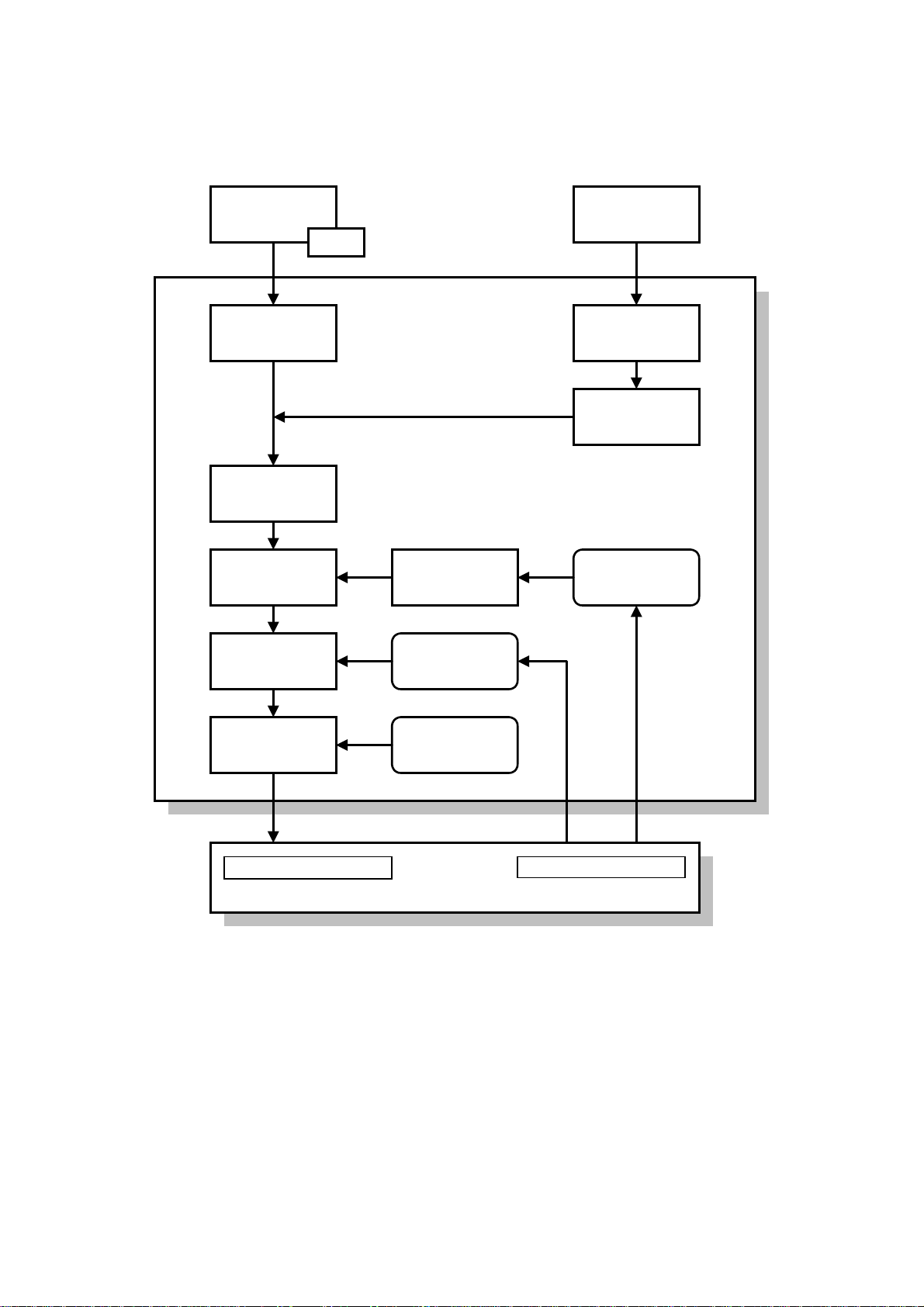
2.3.2 IMAGE DATA PROCESSING FLOW
IPDL-C Driver
BG/UCR
CMYK 8bit
Gamma
Correction
CMYK 8bit
Maximum
Amount
Toner Control
Dithering
CMS
Controller
CMYK 8bit
Gamma
Correction
Table
Maximum
Amount Value
(for service)
PS Driver
RGB 8bit CMYK 8bitRGB 8bit
RPS2 Module
(including CMS)
BG/UCR
Manual Gamma
Correction
CMYK 1/2bit
4bit Expansion
CMYK 4bit
MCU
1/2bit
Text/Photo
Dither
Operation Panel
Printer Engine
G048O706.WMF
2-6
Page 13
30 June 2000 DETAILED DESCRIPTIONS
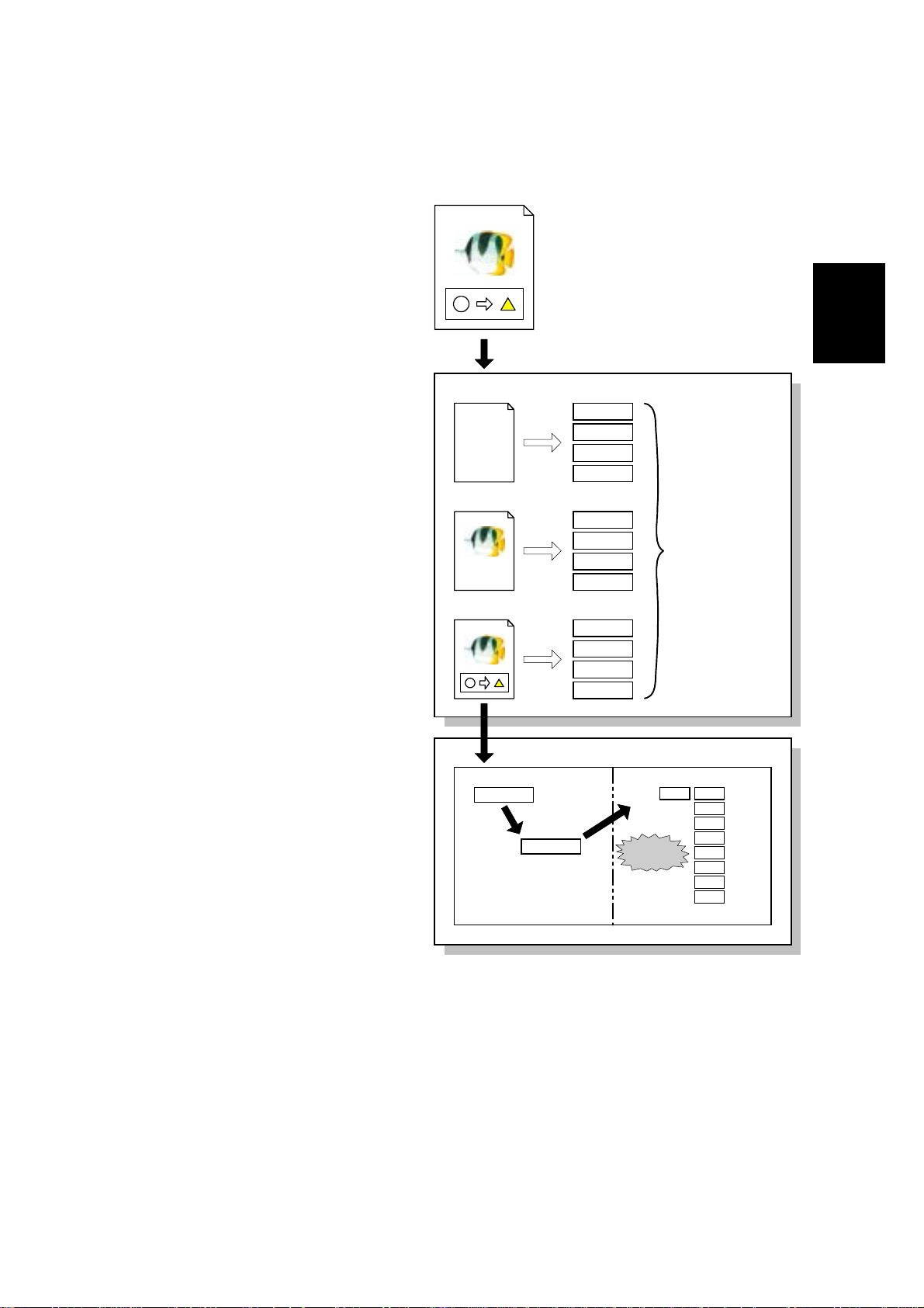
IPDL-C (Intelligent Page Description Language for Color)
The image data received from an
application is separated into three
elements: text, graphics, and
images. Then, the data for each
element is converted to IPDL-C.
The data converted is not done for
the whole page at once. Each
band (area specified) is
independently processed (banding
processing) for the data
conversion as shown in the figure.
The IPDL-C conversion from each
element is stored in free memory
and converted to bitmap data.
Bitmap data is compressed and
stored into the band pool memory ,
DRAM.
After data processing is complete,
the controller sends the
decompressed data to the printer
engine and the engine starts
printing.
APPLICATION
What is IPDL-C....
GDI
TEXT
What is IPDL-C....
IPDL-C
IMAGE
IPDL-C
GRAPHICS
IPDL-C
Detailed
Descriptions
DRIVER
Banding processing
(Converted to IPDL-C)
Free Memory
Converted from
IPDL-C to bitmap
format
CONTROLLER
Band pool memory
Compression
Compressed bitmap data
G048O707.WMF
2-7
Page 14

DETAILED DESCRIPTIONS 30 June 2000
CMS (Color Management System)
CMY realizes to optimize the color print quality by the color profile based on the
characteristics of the printer.
In Rcioh-Script2, CMS functions like the IPDL-C; but RGB conversion is done in
the controller.
CMS is used whenever the color profile setting in the printer driver is set to any
value other than “Off”.
Color Correction by the Driver
The driver adjusts the following parameters in accordance with the driver settings
made by the users: Brightness, Contrast, Saturation, and Color Balance
The driver does not perform RGB to CMYK conversion.
BG/UCR (Black Generation/Under Color Removal)
The RGB data sent to the controller is converted to CMYK data. During CMYK
conversion, some CMY data is replaced with K data by the BG/UCR algorithm.
Gamma Correction
The gamma curve can be adjusted in SP mode. For the adjustment procedure, see
“Section 6:Replacement and Adjustments” in the Controller Service Manual for the
base model (G024).
For CMYK, the density can be adjusted every 15 points from 0 to 100% (0,15, 30,
etc.). The corrected gamma data is stored in NVRAM memory.
The controller performs the gamma correction, RGB/CMYK conversion and
dithering.
→
4bit Expansion
Printer Engine
Process ControlBG/UCR Dithering
Image Density
Adjustment in
Solid Areas
Image Density
Adjustment in
Highlight Area
Printer
Driver
8bit
1/2bit
Controller
Gamma
Correction
Manual
Gamma
Correction
2-8
G048O709.WMF
Page 15

30 June 2000 DETAILED DESCRIPTIONS
Dither Processing
The dither pattern is prepared for the photo, text, graphic and thin lines
independently for 1- and 2-bit modes. These dither patterns creates the illusion of
256 gradations for high quality prints.
The optimum dither pattern is automatically selected based on the Text,
Photographic, and Image elements on the pages.
Maximum Amount Toner Control
The maximum toner amount is controlled in order to prevent toner from being
scattered around texts or lines printed.
The maximum amount values are prepared independently for text and photo. They
can be adjusted by the SP mode
• Default: 300%
• Adjustable range: 100% to 400% (step: 10%)
4 Bit Expansion
When the controller sends the data to the printer engine, the co ntroller expands the
data to 4 bits to meet the image-processing algorithm of the printer engine. When
expanding 1/2 bit to 4 bit, add some of the same data to the original data as shown
in the figure. Even when the data is expanded, dithering remains the same.
1bit
b0
2bit
b1 b0
Detailed
Descriptions
4bit
Expansion
b0 b0 b0 b0'
2-9
4bit
Expansion
b1 b0 b1' b0'
G048O710.WMF
Page 16

30 June 2000 INSTALLATION
3. INSTALLATION
Refer to Section 3 INSTALLATION in the engine service manual.
Installation
3-1
Page 17

30 June 2000 SERVICE TABLES
4. SERVICE TABLES
4.1 CONTROLLER SP MODE
When accessing SP mode, the SP mode menu is add ed to the “Job Timeout”,
“Maintenance” and “Media” menu.
4.1.1 ENTERING AND EXITING CONTROLLER SP MODE
[B][A]
G048O015.WMF
[B][A]
G048O016.WMF
To enter controller SP mode: There are two ways to enter SP mode.
• Turn on the printer while holding down the [On Line] [A] and [Reset] [B] keys on
the operation panel. Hold the keys down until all of the LEDs and the LCD turn
off.
• When on-line, first press [Reset] [B], [On Line] [A], and then press [Enter] [C]
sequentially (don’t take more than a few seconds to press each key).
To exit controller SP mode: There are two ways to enter SP mode.
• Turn the main switch off and on. Be sure to exit from SP mode when you are
finished.
• Follow the procedure for entering SP mode.
Tables
Service
NOTE: When accessing SP mode, “SP” is displayed on the dis play. Do not forget
to exit SP mode after servicing, because users may change the settings or
clear all the settings by accident.
4-1
Page 18

SERVICE TABLES 30 June 2000
4.1.2 MENUS AND DISPLAY
Same as the base model (G024)
4.1.3 SP MODE MENU HIERARCHY
The table below shows the controller SP menu hierarchy. The items in the table
can be accessed in the controller SP mode. When in SP mode, S1 to S9 are added
to the Maintenance menu.
Layer 1 Layer 2 Layer 3 Layer 4
Show Counter Color: xxxxxxx
Black: xxxxxxx
IPDL-C Menu
(displayed if IPDL-C
is selected.)
RPS2 Menu
(displayed if RPS2 is
selected.)
1. Job Timeout Off
2. I/O Timeout 0 – 999 seconds
3. MinLineWidth 1 – 4 dots
4. Toner Usage
1. Color Level 1 bit
2. Color Mode Color
3. Color Set Off
4. ColorProfile Photograph
5. TonerSaving Off
6. Dithering Auto
7. Paper Type Plain Paper
8. Auto Tray SW
9. Duplex Print
A: Duplex Bind Long Edge
B: Job Timeout Off
C. I/O Timeout 0 – 999 seconds
0 – 999 seconds
Off
On
2 bit
Black & White
Vivid
Super Vivid
Fine
Super Fine
Presentation
Solid Color
On
Photographic
Text
OHP
Thick Paper
Plain (Duplex Backside)
Thick (Duplex Backside)
On
Off
Off
On
Short Edge
0 – 999 seconds
It can be accessed if the
meter click mode is
selected.
It can also be accessed
in SP mode.
Same as above
4-2
Page 19

30 June 2000 SERVICE TABLES
Layer 1 Layer 2 Layer 3 Layer 4
RPS2 Menu
(displayed if RPS2 is
selected.)
System Menu
D: Feed Timeout 60 seconds
0 – 999 seconds
E: Print Errors
F: Ktalk Mode Not available
G: Parallel IF1 System Default
H: Parallel IF2 System Default
1. Paper Tray Tray 1
2. Tray Size [*] 8.5 x 13
3. Bypass Use Manual
4. I/O Buffer 16 KB
5. Energy Saver
6. Energy Level Level 1
7. PDL Sensing Auto
8. Transfer Hi-speed
9. Parallel 1
10. Parallel 2
11. Bi-direction
12. OHP Slip
13. Printer Language IPDL-C
Off
On
ACK Inside
ACK Outside
ACK Inside
ACK Outside
By-pass
Tray 2
Tray 3
A5
B4 JIS
B5 JIS
8.5 x 5.5
8 x 13
8.25 x 15
Auto Tray
32 KB
64 KB
128 KB
256 KB
512 KB
Off
5 minutes
15 minutes
30 minutes
45 minutes
60 minutes
Level 2
Manual
Normal
ACK inside
ACK outside
STB down
ACK inside
ACK outside
STB down
Original Mode
Standard
On
Off
RPS
Displayed if an optional
parallel interface board
is installed.
“Tray 2 and 3” are
displayed if an optional
paper feed unit is
installed.
Tables
Service
4-3
Page 20

SERVICE TABLES 30 June 2000
Layer 1 Layer 2 Layer 3 Layer 4
System Menu
Maintenance
14. Language English
French
German
Italian
Dutch
Spanish
Japanese
32. IP ADDRESS to
39. Active PTL.
1. Reinstall Charger
2. Toner Select Cyan
Magenta
Yellow
Black
3. Toner level
4. Registration Byps.: Vert.
Bypass/Thick: V
Tray: Vert.
Dup.: Vert.
Tray1: Horiz.
Tray2: Horiz.
Tray3: Horiz.
5. Toner Empty Continue
Stop
6. Menu Reset
7. Menu Protect Off
On
8. Log Protect Off
On
9. Log Clear If “Menu Protect” is
10. Ethernet Auto
10 Mbps
100 Mbps
S1. Maint. Page
S2. Color Chart
S3. Maint. Clear Fusing Unit
S4. Clear All Mem.
Displayed if an optional
network interface board
is installed.
“Tray 2 and 3” are
displayed if an optional
paper feed unit is
installed.
It can also be accessed
if the [Enter], [Escape],
and [Menu] keys are
pressed in sequence
when the printer is on
line. It is always
displayed in SP mode.
Same as above
selected, it is not
displayed.
It can also be accessed
if the [Enter], [Escape],
and [Menu] keys are
pressed in sequence if
the printer is on line,
and if an optional
network interface board
is installed. It is always
displayed in SP mode.
4-4
Page 21

30 June 2000 SERVICE TABLES
Layer 1 Layer 2 Layer 3 Layer 4
Maintenance
List Print
S5. Gamma Calib.
S6. Printer ID Not used
S7. Toner Limiter Text
S8. Brand RICOH.EXP
S9. Meter Click Off
1. Config. Page
2. Color Sample
3. Job Log
4. Statistics
IPDL-CSelect PDL
OPTION#1 RPS2
Load Setting Default
Setting-Old
Setting-Current
Mode Select 1 bit/photo, 2 bit/photo
1 bit/Text, 2 bit/text
Print Sheet
Gamma Select Black
Cyan
Magenta
Yellow
Save Settings
Photo
It can be accessed only
SAVIN
NRG
Infotec
Gestetner
LANIER
RICOH.JPN
Print/Japan
Develop. Count
Print Count
Print/Japan: D
Dev.Count: D
Print Count: D
if [W], [V], and [Menu]
keys are pressed in
sequence.
Tables
Service
4-5
Page 22

SERVICE TABLES 30 June 2000
4.1.4 SP MODE DETAILS
S1. Maintenance Sheet
The table below explains the contents of the engine maintenance list printout. The
controller obtains the data from the engine (MCU).
Item Description
MCU version The MCU board firmware version number.
Toner density Toner density can be adjusted via the Maintenance. Menu by customers.
Adjusted values are stored in NVRAM on the MCU.
Registration Side registrations from Optional tray can be adjusted with Maint. Menu by
customers. And leading edge registration can be done with engine SP mode
(1. Margin). These values are stored in NVRAM on the MCU.
Total counter Indicates the total number of printouts. The counter is incremented when the
paper exit sensor detects paper exit completion (regardless of paper size,
type, and mono/color mode).
Color Counter value printed in color mode.
Mono color Counter value printed in black mode.
PCU counter PCU replacement is indicated when this value reaches 72000. This value is
incremented by 4 in color mode printing and by 1 in Black mode printing
except A3/DLT. When printing with A3/DLT, double counting occurs.
Fusing unit Fusing unit replacement is indicated when this value reaches to 60000. This
counter is incremented by 2 for A3/DLT size printing and by 1 for other size
printing.
Fusing
unit/Counter
reset time
Charger
Counter
Charger Reset
Counter
A3/DLT, A4/LT,
LG, B4 and
Other Size
counter
Feed Jam,
Transfer Jam
and Exit Jam
counter
Feed Jam,
Transfer Jam
and Exit Jam
counter (Duplex)
SC counter Number of SCs
Meter Click Type of counting method for meter click mode
Count by
developments
Count by prints Number of prints. This counter increases by 1 for any size printing.
Count by
developments
(A3/DLT double)
Count by prints
(A3/DTL double)
Number of Fusing unit resets with controller SP mode (S3).
Charger replacement is indicated when this value reaches to 24000.
Number of Charger resets with controller UP mode.
Number of each size paper that passed the exit sensor.
Number of paper jams in each section.
Number of paper jams in each section for duplex printing.
Number of developments. This counter increases by 1 when a print of any
size is made.
Number of developments. This counter increases by 2 for A3/DLT size
printing and by 1 for all other sizes.
Number of prints. This counter increases by 2 for A3/DLT size printing and by
1 for all other sizes.
4-6
Page 23

30 June 2000 SERVICE TABLES
Item Description
Count by prints
(Japan)
Count by prints
(Japan:A3/DTL
double)
SC Logging The most recent 3 SC codes.
Jam Logging The most recent 10 jamming codes and the total counter value at the time.
Process-Control
Error Logging
ID sensor PWM The value set with engine SP mode, 9: ID Sensor PWM.
Not used.
Not used.
000: At paper cassette
001: At paper pass
002: At paper exit
The most recent 3 errors while process control and the total counter value at
the time.
Not all of the errors are indicated as SC errors.
S2. Color Chart
Same as the base model (G024)
S3. Maintenance Clear
Same as the base model (G024)
S4. Clear All Memory
Executing this function resets the following user settings, stored in the NVRAM on
the controller, to their default values:
• System Menu
• Printer ID
• Printer name on the network
• Gamma (γ) calibration
• Brand
γγγγ)
S5. Gamma (
)
Calibration
) )
Same as the base model (G024)
S6. Printer ID
Tables
Service
Not used for this model.
NOTE: This is used for controller identification when installing fonts for Ricoh-
Script 2 onto the hard disk. However, since it is not possible to install the
hard disk in this model, it is not necessary to set the printer ID.
4-7
Page 24

SERVICE TABLES 30 June 2000
S7. Toner Limiter
The maximum toner values can be adjusted from 100 to 400% for both Text and
Photo Modes. The default value for both is 300%.
If this value is set high, the printed image appears more true to the original data.
However, since a greater amount of toner is used, it is easy to scatter the toner
around lines and text areas. If the value is set low, the color balance of low-density
areas varies, however toner does not scatter as easily.
NOTE: The values for the maximum toner amount are fixed for the base model
(G024), but adjustable for the G047/48.
S8. Brand (Default Setting: RICOH.EXP)
Use this mode to specify the brand. The machine will then display the correct
model name on the LCD and in the configuration page header.
NOTE: This must be done before delivering the printer to the customer site.
S9. Meter Click
In this mode, the counting method can be selected depending on the type of
Service Contract.
When the mode is activated:
1. A new user mode, “Show Counter” displays the counter values.
2. The printer will stop printing when toner has run out. In addition, “Toner Empty”
disappears from the Maintenance menu.
3. The configuration sheet includes the value for the counting method selected in
Meter Click mode, not the total counter value. Both counter values are included
in the engine maintenance sheet.
4. After selecting meter clock mode, the counter value for the selected counting
method is automatically set to 0. However, it cannot be reset to 0 after the
machine begins counting.
5. All developments/prints are counted at paper exit.
4-8
Page 25

30 June 2000 SERVICE TABLES
6. Counting method:
1) By developments
Black 1C 2C 3C Full col or
Full color +1 +2 +3 +3
Black and white +1 +1
NOTE: If the meter click mode is set to “Dev. Count: D”, it is incremented by 2
for A3/DLT size.
2) By prints
Black 1C 2C 3C Full col or
Full color +1 +1 +1 +1
Black and white +1
If the meter click mode is set to “Print Count: D”, it is incremented by 2 for
A3/DLT size.
7. The following are not counted:
1) A sheet of paper that is placed between printed transparencies in OHP Slip
Mode.
2) The final page when printing an odd number of pages in duplex mode.
3) The engine maintenance sheet, color chart and gamma calibration sheets in
controller SP mode.
4) All sheets printed out in engine SP mode.
5) The Low-Memory Error Sheet.
6) A list of settings (B/W) if a non-fatal error is detected during Self-Diagnostics.
Tables
Service
8. “Change Fuser”, “Change PCU”, and “Need Charger” are not displayed.
IPDL-C Menu
Item Description
3. MinLineWidth Adjust s the minimum line width within 1 to 4 dots.
4. Toner Usage
Displays the toner usage independently for each color when printing
the page. (Number of dots on the page/ maximum number of dots)
Media Menu ([Media] key)
Controller SP mode adds special menu items to the user menu accessed from the
[Media] (access by pressing the [Media] key, then scroll through the menu on the
display) menu.
Menu Item Function/Use
Displays the currently installed versions of the controller system,
3. Summary
emulation modules, and engine (MCU) firmware, and the amount of
memory installed in the controller.
4-9
Page 26

SERVICE TABLES 30 June 2000
4.2 POWER-UP SELF-DIAGNOSTICS
Same as the base model (G024)
4.3 POWER-UP SELF-DIAGNOSTICS FLOW CHART
Turn on power
Diagnostic
Code ROM sum check
Test Code ROM
Fatal Error Detected
Read/write test
Frequency check
Test of timer functions
of Rocky R
Operation Test
Font ROM sum check
DIMM (RPS2) sum check
Test Standard RAM
Test CPU
Test Timer
Test FPU
Test Font ROM
Test DIMM
Start System
Non-fatal Error
(user error)
No
Fatal Error Detected
Fatal Error Detected
Fatal Error Detected
Fatal Error Detected
Fatal Error Detected
Display Error on LCD
Yes
Print List of Settings
(Black/white)
Standby Condition
4-10
G048O711.WMF
Page 27

30 June 2000 SERVICE TABLES
4.4 DETAILED SELF-DIAGNOSTICS MODE
Same as the base model (G024)
4.5 DETAILED SELF-DIAGNOSTICS FLOW CHART
Turn on power
Diagnostic
Code ROM sum check
Test Code ROM
Fatal Error Detected
Read/write test
Frequency check
Test of timer functions
of Rocky R
Read/write test
Operation test
Loop back test on the
standard parallel interface
Read/write test
Font ROM sum check
DIMM (RPS2) sum check
Test Standard RAM
Test CPU
Test Timer
Test Optional RAM
Test FPU
Test Parallel Interface
Test NVRAM
Test Font ROM
Test DIMM
Fatal Error Detected
Fatal Error Detected
Fatal Error Detected
Fatal Error Detected
Fatal Error Detected
Fatal Error Detected
Fatal Error Detected
Fatal Error Detected
Display Error on LCD
Tables
Service
Start System
Non-fatal Error
No
Print List of Settings
(Color)
Standby Condition
4-11
Yes
Print List of Settings
(Black/white)
G048O712.WMF
Page 28

30 June 2000 PERIODIC MAINTENANCE
5. PERIODIC MAINTENANCE
Refer to Section 5 Periodic Maintenance in the engine service manual.
Periodic
Maintenance
5-1
Page 29

30 June 2000 REPLACEMENT AND ADJUSTMENT
6. REPLACEMENT AND ADJUSTMENT
6.1 CONTROLLER BOARD REPLACEMENT
Refer to section 6.7.1 Controller Board of the Engine Service manual for the
replacement.
6.2 IMAGE ADJUSTMENT
Same as the base model (G024)
6.3 SOFTWARE UPGRADE PROCEDURE
The controller, Ricoh-Script 2, and network interface boards have a flash ROM for
storing control software. This allows version upgrades using an IC card.
The engine firmware cannot be upgraded using this procedure. See the engine
service manual for details on how to upgrade the engine firmware.
NOTE: Before starting an upgrade procedure, make sure that the software in the
IC card is newer than the software in the controller, Ricoh-Script 2, or
network interface board.
To check, do one of the following:
• Print out a configuration page (user mode).
• Enter controller SP mode and execute “3. Summary” with the [Media]
key. The software version is shown on the operation panel LCD.
Follow the procedure shown below to upgrade the software:
1. Turn off the machine, and then unplug all cables from the parallel interface
boards and network interface board, if connected.
2. For the duplex model only: Open the vertical transport unit.
3. Remove the controller board cover.
4. Remove the controller board and then install the upgrade IC card in the card
slot.
5. Turn on the machine. The machine automatically copies the software from the
IC card to the appropriate IC (controller, Ricoh-Script 2, or network interface
board).
Adjustment
Replacement
CAUTION: Do NOT turn off the machine while the software is being updated.
Otherwise, the controller, NIB, or Ricoh-Script 2 module may be
damaged.
6-1
Page 30

REPLACEMENT AND ADJUSTMENT 30 June 2000
For the controller or Ricoh-Script 2:
The LCD display on the operation panel changes as shown below as the
rewrite procedure proceeds. (‘MELT’ is displayed during the software upgrade
for Ricoh-Script 2 since it involves a decompression process.)
(MELT ->) ERASE -> WRITE -> VERIFY -> OK!!OK!!
The appearance of the message “OK!!OK!!” indicates that the controller has
received the data from the IC card. However, note that it takes about 30
seconds to rewrite the data in the controller or Ricoh-Script 2 after this message
is displayed.
The message NG!!NG!!” is displayed if an error occurs during the rewrite
process. If this condition occurs, reinstall the IC card and turn the power off and
on again.
For the network interface board:
The appearance of the message “DOWNLOAD OK.” indicates that the
controller has received the data from the IC card. However, note that it takes
about 30 seconds to rewrite the data in the network interface board after this
message is displayed.
DOWNLOAD -> ############ -> DOWNLOAD OK.
The message “DOWNLOAD NG.” is displayed if an error occurs during the
rewrite process. If this condition occurs, reinstall the IC card and turn the power
off and on again.
1. When the rewrite ends, turn off the main unit, and remove the IC card.
2. Close the controller board cover.
3. For the duplex model only: Close the vertical transport unit.
4. Turn the power on again and print the user mode configuration page.
5. Check the new software version listed on the configuration page and make
sure that it matches the version on the IC card.
6-2
Page 31

30 June 2000 TROUBLESHOOTING
7. TROUBLESHOOTING
7.1 TYPES OF PROBLEMS
The problems can be classified as follows:
Printer-side Print Settings
•
Operation
Hardware
Printer-side Initial Settings
•
Host-side Application Settings
•
•
Faulty Engine
•
Faulty Controller
•
•
•
•
•
Main Unit
Option
Consumables
Main Unit
Option
Software
Operating
conditions
•
Hardware Limitations
Bug in Controller ROM
•
Bug in Emulation Module Software
•
•
Controller Limitations
Bug in Host-side Application
•
Host-side Application Limitations
•
Environment (power, temperature and humidity,
•
dust, noise, vibration)
•
Consumables
G048O014.WMF
Trouble-
shooting
7-1
Page 32

TROUBLESHOOTING 30 June 2000
7.2 TROUBLESHOOTING PROCEDURE
7.2.1 HARDWARE TESTS
Same as the base model (G024)
7.2.2 OPERATION-RELATED TESTS
Same as the base model (G024)
7.2.3 SOFTWARE-RELATED TESTS
Same as the base model (G024)
7-2
Page 33

30 June 2000 TROUBLESHOOTING
7.3 ERROR MESSAGES
7.3.1 OVERVIEW
The error messages for this unit are classified as follow s :
1. Controller Self -diagnostic Errors
Errors detected while the unit performs power-up self-diagnostics/detailed selfdiagnostics on the controller hardware.
2. Controller User Erro rs
Errors caused because the controller software cannot process the job because
of, for example, insufficient memory.
3. Internal Errors
Errors caused because the controller’s control function fails to function
normally.
4. Engine User Errors (Cautionary)
Errors that do not require user intervention to continue printing (the printer can
still communicate with the PC over the interface). However, for the best printing
quality, the user should correct the problem as soon as possible.
5. Engine User Errors
Severe errors that cause the unit to stop printing, requiring the user to fix the
problem before printing again.
6. Engine Service Codes (SCs)
Severe errors that cause the unit to stop printing, requiring a technician to fix
the problem before printing again.
Only one error message can be displayed at a time. There is an order of priority for
displaying errors. This is as follows, starting with the highest priority: Internal
Errors, Controller Self-d iagnostics Errors, Engine Service Codes (SCs), Engine
User Errors, Engine User Errors (Cautionary), and Controller User Errors.
Trouble-
shooting
7-3
Page 34

TROUBLESHOOTING 30 June 2000
7.3.2 CONTROLLER SELF-DI AGNOSTICS ERRORS
When a contro ller self-diagnostics error occurs, the error code is displayed on t he
first line of the operation panel LCD.
The second line contains an 8-digit code that gives details of the error for
designers to debug. For a memory error, the second line of the LCD indicates the
address where the error occurred. For errors other than memory errors, the second
line always reads “FFFFFFFF”.
Code Description Location
00XX Exception processing error Controller
0101 Code ROM sum check error Controller
0201 Standard memory read/write error Controller
0301/0401
060X CPU exception self-diagnostics error Controller
0D0X ASIC timer error Controller
0EXX AISIC operation panel interface error Controller
110X
1401 NVRAM error (Read/W rit e) Controller
160X Font ROM error (Sum) Controller
1B0X Optional Interface 1 Error Contr o ller
1C0X Optional Interface 2 Error Controller
1D0X
250X
400X FPU er r or Controller
Optional memory read/write error
Non-fatal error (printed as B0 in the error log.)
ASIC Centronics interface error
Non-fatal error (printed as B1 in the error log.)
Optional parallel interface board error
Non-fatal error (printed as B6 in the error log.)
DIMM (emulation module) error
Non-fatal error (printed as B5 in the error log.)
Optional memo ry
Controller
Optional parallel
interface board
Emulation
module/Controller
7-4
Page 35

30 June 2000 TROUBLESHOOTING
7.3.3 CONTROLLER USER ERRORS
Display Description Location/action
85: Error
86: Error
91: Error
94: Error
A3: Error
Graphics environment initialization
error
Invalid control code parameter I ncorrect pr inter driver or incorrect
Font/image environment
initialization error
Download data error
Receive buffer overflow Increase the I/O buffer size using
A6: Error Overflow during compression Install additional memory.
Error during drawing processing Use a smaller font size or a less
A7: Error
Error during library drawing Switch the machine off/on. If that
A8: Error
AB: Error Print overrun Install additional memory.
B0: Error Optional memory error Reinstall/replace optional memory.
B1: Error Standard parallel interface error Interface cable/controller
Invalid initial set-up setting Reset the printer settings using
B3: Error
B4: Error IC card slot error Controller/IC card
B5: Error Optional emulation module error Reset/replace emulation module.
B6: Error
B7: Error
Optional parallel interface board
error
Optional network interface board
error
Optional memory/Controller
cable installed
Install additional memory.
Incorrect ‘total memory size’ setting
in the driver
the system menu (user mode)
complex font, or replace the
controller
does not work, replace the
controller.
‘Menu reset’ in the Maintenance
menu (user mode).
Reset/replace optional parallel
interface board
Reinstall/replace network interface
board
7-5
Trouble-
shooting
Page 36

TROUBLESHOOTING 30 June 2000
7.3.4 INTERNAL ERRORS
When an internal error occurs, the mes sage “Power Off/On” is displayed on the
first line of the operation panel LCD. The internal error code is on the second line in
the format “Error XXYY-ZZZZZZZZ” (“XX” denotes a classification code; “YY”
denotes a process number, and “ZZZZZZZZ” indicates the program address where
the error occurred).
The classification code portions (XX) and their descriptions are shown below. The
“YY” and “ZZZZZZZZ” portions are for designer use only (for debugging).
Code (XX) Description
00 Error in the TLB user area.
01 CPU TLB update exception
02 CPU mismatch exception (load or fetch)
03 CPU mismatch exception (store)
04 CPU address error exception (load or fetch)
05
06 CPU bus error exception (load or fetch)
07 CPU bus error exception (store)
08 CPU system call exception
09 CPU break point exception
10 CPU reserved instruction exception
11 CPU coprocessor disabled exception
12 CPU operation overflow exception
13 CPU trap exception
14 Coherency (instruction) error
15 CPU floating-point operation exception
16 CPU timer interrupt
17 ROCKY level 4 interrupt (ART or Tim)
18 ROCKY level 3 interrupt (CP)
19 ROCKY level 2 interrupt (XINT1 or XINT0)
20 ROCKY level 1 interrupt (CBE, DBE, Dt c0, Verr , Fin, Vdtc, Fout)
21 ROCKY level 0 interrupt (Debug)
22 Software interrupt
23 Software interrupt
24 Other CPU exceptions
25 Memory allocation error
26 Overflow error
27 Frame allocation error
28 Card eject error
29 Printer engine error
30 Option board error
31 Session-to-network interface board communications error
CPU address error exception (store)
7-6
Page 37

30 June 2000 TROUBLESHOOTING
7.3.5 ENGINE USER ERRORS (CAUTIONARY)
The unit can continue printing even when one of the messages listed below is
encountered.
Display Description
Change Fuser
Change PCU Photoconductor unit
Need Charger Charger replacement time
Low on: XXX Toner near end
Add Fusing Oil Fusing oil near end 100
Waste T Full Waste toner bottle is nearly full. 20
Fusing unit replacement time
arrived.
replacement time arrived
arrived.
XXX denotes the color name
(CMYK or their combination).
Number of sheets until
warning state
Information only
Information only
Information only
100
NOTE: “Change Fuser”, “Change PCU”, and “Need Charger” are not displayed if
meter click mode is selected by SP mode.
7.3.6 ENGINE USER ERRORS
The unit can no longer continue printing when this error message is displayed.
Refer to the Troubleshooting section in Setup Guide of Operating Instructions.
7.3.7 ENGINE SERVICE CODES
Refer to the Troubleshooting sectio n in Engi ne Ser vice manual.
7-7
Trouble-
shooting
Page 38

30 June 2000 OVERVIEW
8. NETWORK INTERFACE BOARD (C4000 FERRET)
8.1 OVERVIEW
8.1.1 SPECIFICATIONS
Configuration: Embedded
LAN Interface: 100BASE-TX/10BASE-T
Frame Type: Ethernet II, IEEE802.3, IEEE802.2, SNAP
Protocol: TCP/IP, AppleTalk, NetWare, NetBEUI
SNAP: MIB-II, PrinterMIB, HostResourceMIB, RicohPrivateMIB
8.1.2 BLOCK DIAGRAM
Controller
Board
Option Bus I/F
Network
Environment
CPU
ASIC
Ethernet
Controller
Filter Module
LAN I/F
Flash ROM
1MB
SDRAM
8MB (64Mb)
EEPROM
1Kb
Options
8-1
G048O713.WMF
Page 39

COMPONENT LAYOUT 30 June 2000
8.2 COMPONENT LAYOUT
8.2.1 NETWORK INTERF ACE BOARD DIAGRAM
Flash
ROM
MB87L1231
8.2.2 DEVICES
ASIC
SDRAM
CPU
HD6417612
Ethernet
Controller
AM79C973
RJ-45
LED4(G)
LED3(G)
EEPROM
LED1(Y)
SW2
G048O705.WMF
Device Description
CPU HD6417612RF
ASIC MB87L1231
Flash ROM MBM29LV800BA-70PFTN (8 Mbit)
SDRAM 64Mbit: 100MHz
EEPROM M93C46-WMN6 (1kbit)
Ethernet Controller AM79C973KC/W
8-2
Page 40

30 June 2000 BASIC OPERATIONS
8.3 BASIC OPERATIONS
8.3.1 OVERVIEW
This network board can manage both 100BASE-TX and 10BASE-T. It has a
maximum data transfer speed of 100Mbps.
The auto-negotiation function automatically switches the communication speed.
The controller board supplies the power source (+5V) and provides the reset
signal. The controller board communicates with the network interface board
through the option I/F connector.
The function of LED and SW is as follows;
Functions
LED1
LED2 Not used
LED3
LED4
SW1
Displays the operating status.
ON: Ready, OFF: Busy
Displays the LAN Type.
ON: 100 BASE-TX, OFF: 10 BASE-T
Displays the link status.
ON: Link safe, OFF: Link failure or Link disable
Resets the NVRAM on the network interface board.
NOTE:This board has the hardware to execute a “Summary Printout”.
However, it does not function on this printer due to the controller
specifications.
8-3
Options
Page 41

BASIC OPERATIONS 30 June 2000
8.3.2 SWITCH FUNCTION
SW1 resets the NVRAM on the network interface board.
NOTE: This board has the hardware to execute a "Summary Printout". However, it
does not function on this printer due to controller specifications.
NVRAM Reset Procedure
This procedure resets all the network settings to the defaults.
• IP address, Subnet Mask, Default Gateway Address, Access Control Mask,
Network Boot, Frame Type (NetWare), Active Protocol, and so on
1. Turn on the main switch while pressing SW1. Keep pressing SW1 for 15
seconds.
2. Release SW1 for 3 seconds, press it again for 3 seconds, and then release it.
3. Turn the main switch off/on to complete the NVRAM reset procedure.
NOTE: There is a margin of less than 1 second for error. Use a watch to
measure the time periods as accurately as possible.
4. Print out the configuration page, and then check the settings. If the procedure
failed, the previous settings remain. Repeat the above procedure until the old
settings have been cleared.
8-4
 Loading...