

Page 1

FRESA PS (G024)
SERVICE MANUAL
[Controller]
Page 2

IMPORTANT SAFETY NOTICES
ø
PHYSICAL INJURY PREVENTION
1. Before disassembling or assembling parts of the printer and peripherals,
make sure that the power cord is unplugged.
2. The wall outlet should be near the printer and easily accessible.
3. Note that some printer components are supplied with electrical voltage even
if the main switch is turned off.
4. If an adjustment or operation check must be made requiring the removal or
opening of the exterior covers while the main switch is on, keep hands away
from electrified or mechanically driven components.
5. The printer drives some of its components when it completes the warm-up
period. Keep hands away from mechanical and electrical components when
the printer starts operation.
6. The interior and metal parts for the fusing unit become extremely hot while
the printer is operating. Do NOT touch these components with bare hands.
HEALTH SAFETY CONDITIONS
1. Never operate the printer without ozone filters installed.
2. Always replace the ozone filters with the specified replacement at the
specified maintenance intervals.
3. Toner is non-toxic, but if it gets in your eyes by accident, it may cause
temporary eye discomfort. Remove it with eye drops or flush eyes with
water. If this is unsuccessful, get medical attention immediately.
SAFETY AND ECOLOGICAL NOTES FOR DISPOSAL
1. Do NOT incinerate toner cartridges, development toner magazine (DTM) or
used toner. Toner dust may ignite suddenly when exposed to an open
flame.
2. Dispose of used toner bottle and photoconductor unit (PCU) in accordance
with local regulations. (These are non-toxic supplies.)
3. Dispose of replaced parts in accordance with local regulations.
Page 3

Trademarks
Microsoft, Windows 95/98, and Windows NT 4.0 are registered trademarks of
Microsoft Corporation.
Macintosh and EtherTalk are registered trademarks of Apple Computer, Inc.
PostScript is a registered trademark of Adobe System Inc.
PCL is a registered trademark of Hewlett-Packard Company.
NetWare is a registered trademark of Novell, Inc.
Ethernet is a registered trademark of Xerox Corporation.
Token Ring is a registered trademark of IBM Corporation.
General Notice:
Other product names used herein are for identification purposes only and may be
trademarks of their respective companies. We disclaim any and all rights in those
marks.
Page 4

TABLE OF CONTENTS
1. OVERALL MACHINE INFORMATION........................................1-1
1.1 SPECIFICATIONS.................................................................................... 1-1
1.2 LAYOUT ................................................................................................... 1-2
2. FUNCTIONAL OVERVIEW .........................................................2-1
2.1 BLOCK DIAGRAM AND FUNCTIONS...................................................... 2-1
CPU ..................................................................................................... 2-1
Memory................................................................................................ 2-1
DRAM .................................................................................................. 2-2
SRAM................................................................................................... 2-2
NVRAM Functionality........................................................................... 2-2
Fiery Rip Chips (EFI ASICs)................................................................. 2-3
Real Time Clock................................................................................... 2-3
2.2 PRINT DATA PROCESSING.................................................................... 2-4
2.3 BUILT-IN COLOR MANAGEMENT .......................................................... 2-5
3. INSTALLA T ION...........................................................................3-1
4. SERVICE TABLES AND PROCEDURES...................................4-1
4.1 DIAGNOSTICS MODE............................................................................. 4-1
4.1.1 OVERVIEW ..................................................................................... 4-1
Map of the Diagnostic Menu ................................................................ 4-1
4.1.2 RUNNING THE DIAGNOSTICS ...................................................... 4-2
Basic Procedure................................................................................... 4-2
Using the Custom Diagnostics Set....................................................... 4-3
Diagnostic Test Result Display............................................................. 4-4
Exit Custom Menu................................................................................ 4-4
4.1.3 CONTENTS OF INDIVIDUAL DIAGNOSTIC TESTS ...................... 4-5
IDE Diagnostic Test ............................................................................. 4-5
Ethernet Diagnostics............................................................................ 4-6
RAM Diagnostics.................................................................................. 4-7
Video Chip Diagnostics........................................................................ 4-8
Boot ROM Diagnostics......................................................................... 4-8
Firmware Diagnostics........................................................................... 4-8
I2CEEPROM diagnostics..................................................................... 4-8
4.2 BOOT ROM MENU................................................................................... 4-9
4.2.1 PURPOSE OF THE ROM MENU.................................................... 4-9
Entering the Boot ROM Menu.............................................................. 4-9
Contents of the Boot ROM Menu......................................................... 4-9
Exiting the Boot ROM Menu................................................................. 4-9
4.2.2 NAVIGATING THE MENU............................................................. 4-10
Boot ROM menu map ........................................................................ 4-10
Key Usage in the Main Menu............................................................. 4-11
Key Usage in each Menu Item........................................................... 4-11
1
Page 5

4.2.3 DISPLAYING VERSION INFORMATION...................................... 4-11
4.2.4 INSTALLING SOFTWARE UPGRADES........................................ 4-12
Preparation ........................................................................................ 4-12
Procedure .......................................................................................... 4-12
Recovery Mechanism......................................................................... 4-12
4.2.5 FORMATTING THE HARD DISK................................................... 4-13
Procedure .......................................................................................... 4-13
4.2.6 CHANGING THE ETHERNET MAC ADDRESS............................ 4-13
Preparation ........................................................................................ 4-13
Procedure .......................................................................................... 4-13
4.2.7 BRAND NAME SELECTION.......................................................... 4-14
Preparation ........................................................................................ 4-14
Procedure .......................................................................................... 4-14
4.2.8 CLEARING THE NVRAM PARAMETERS..................................... 4-14
Procedure .......................................................................................... 4-14
4.3 SERVICE MODE.................................................................................... 4-15
4.3.1 OVERVIEW ................................................................................... 4-15
Password........................................................................................... 4-15
Service Menu Map............................................................................. 4-15
Entering the Service Menu................................................................. 4-15
4.3.2 PRINT SERVICE INFORMATION LIST......................................... 4-16
4.3.3 PRINT COLOR CHART................................................................. 4-17
4.3.4 CLEAR FUSER CTR ..................................................................... 4-17
5. PERIODIC MAINTENANCE........................................................ 5-1
6. REPLACEMENT AND ADJUSTMENT........................................6-1
6.1 CONTROLLER BOARD REPLACEMENT................................................ 6-1
7. TROUBLESHOOTING.................................................................7-1
7.1 TYPES OF PROBLEMS........................................................................... 7-1
7.2 TROUBLESHOOTING PROCEDURE...................................................... 7-2
7.2.1 HARDWARE TESTS ....................................................................... 7-2
7.2.2 OPERATION-RELATED TESTS...................................................... 7-2
7.2.3 SOFTWARE-RELATED TESTS...................................................... 7-3
7.3 ERROR MESSAGES................................................................................ 7-4
7.3.1 OVERVIEW ..................................................................................... 7-4
7.3.2 CONTROLLER DIAGNOSTICS ERRORS ...................................... 7-5
7.3.3 ENGINE USER ERRORS (CAUTIONARY)..................................... 7-7
7.3.4 ENGINE SERVICE CODES............................................................. 7-7
2
Page 6

12 May, 1999 OVERALL MACHINE INFORMATION
1. OVERALL MACHINE INFORMATION
1.1 SPECIFICATIONS
Page Description Language: Adobe PostScript 3
PCL 5e/5c compatible
Printer Driver Platform: Macintosh, Windows 95/98, Windows NT4.0
Resolution: 600 dpi
Gradation Mode: 2 bits/pixel
Interface: IEEE1284 Compatible, Nibble or ECP mode
Ethernet 10BaseT/100BaseTX, 10Base 5
Network Protocol: NetWare 3.10, 3.11, 4.X, IPX/SPX
EtherTalk System 7 and later
TCP/IP, SNMP, ARP, UDP
Frame Types: 802.2, 802.3, SNMP, Ethernet-II, Ether net SNMP
Printing Services: LPD (Line Printer Daemon)
Pserver (Print Server)
PAP (Printer Access Protocol)
SMB (Server Message Block) over TCP/IP
Overall
Information
Font: 136 PostScript fonts
35 Intelli fonts, 10 TrueType fonts, and 1 bitmap
line printer font for PCL5c
Memory: Standard 32MB
DIMM Slots: 2 (for optional memory)
EIDE Interface: 1 (for optional HDD)
Options: 32/64MB DIMM
2.5-inch 1.6-GB hard disk drive
1-1
Page 7
LAYOUT 12 May, 1999
1.2 LAYOUT
2
1
1. Controller
2. MCU
G024O011.WMF
1-2
Page 8
12 May, 1999 FUNCTIONAL OVERVIEW
2. FUNCTIONAL OVERVIEW
2.1 BLOCK DIAGRAM AND FUNCTIONS
CPU
MIPS R4700
Memory
Controller
ASIC (DX)
Video Control
ASIC (VX)
IDE
Controller
I/F Control
ASIC (IX)
Power
Supervisor
On Board
Flash ROM
(Boot Code)
SDRAM
Flash ROM
4 DIMM Slots
PCI
Connector
Engine I/F
Connector
IDE HDD
Connector
IEEE 1284
Connector
System I2C
EEPROM
Detailed
Descriptions
Token Ring
Card (Option)
Ethernet RJ45
Ethernet
Controller
Connector
Ethernet AUI
Connector
G024C503.WMF
CPU
This is a MIPS R4700 (133 MHz).
Memory
There is a proprietary memory ASIC that supports up to 8 DIMMs, up to 32 MB of
boot PROM or flash memory. The ASIC can support burst accesses for 8 or 64 bit
wide PROMs.
However, this controller only supports 4 DIMMs. Three of these are for optional
memory, and one is for the flash/mask ROM that holds internal fonts.
2-1
Page 9

BLOCK DIAGRAM AND FUNCTIONS 12 May, 1999
DRAM
The Memory ASIC supports industry standard synchronous DRAM DIMMs for
optional printer memory (see the previous page).
The R4700 bus is 64 bits wide. Architecturally, the system can support up to 256
bytes of DRAM and 8 DIMM slots (64 MB DIMMs will be supported when
commercially available).
SRAM
The SRAM is used for processing print data.
NVRAM Functionality
The NVRAM holds printer parameters that must be maintained across power
cycles. NVRAM space is in the order of 32KB.
The NVRAM consists of 1 MB of flash memory soldered to the motherboard.
2-2
Page 10

12 May, 1999 FUNCTIONAL OVERVIEW
Fiery Rip Chips (EFI ASICs)
The three ASICs (designed by EFI) are responsible for the high-speed and
performance of the controller. They are as follows:
Memory ASIC (DX3)
This provides high speed interfaces between the CPU, memory, and PCI bus. The
DX3 supports 64-MB DRAM DIMMs.
IO ASIC (IX)
This supports the internal and external I/O interfaces including:
•
PCI direct memory access
•
User interface (front panel)
•
IEEE 1284 compliant parallel port (Centronics, Nibble, ECP)
•
Generic synchronous serial interface
Video ASIC (VX)
The video ASIC is responsible for:
•
PCI direct memory access
•
Decompression
•
Video interface to the engine
All three ASICs interface to a high speed PCI bus (64 bits wide) and comply Rev
2.1 of the PCI specification.
Real Time Clock
The controller does not have a real time clock.
Detailed
Descriptions
2-3
Page 11

PRINT DATA PROCESSING 12 May, 1999
2.2 PRINT DATA PROCESSING
Drivers Connectivity
PostScript
generation
PCL
generation
Ethernet
Parallel
IO/Print/
Device Mgr
Spooling, PDL
switching
PDLs Compression Page Mgr
DSC
parsing
PostScript
PJL parsing
PCL 5e/5c
Page
Compression
Page
Compression
Engine loading
The key roles of each part of the print system are outlined below.
•
The
drivers
are responsible for generating the page description on the host
system and for transmitting data to the printer.
•
I/O manager
The
mediates the connection between the parallel port or
network interface and establishes a device or print manager connection.
•
print manager
The
is responsible for spooling the job (if appropriate) and for
feeding jobs to the correct PDL interpreter.
•
PDL interpreters
The
are responsible for turning page descriptions into
rendered pages and for parsing job management comments.
•
•
compression
The
page manager
The
subsystem manages compressed pages in memory.
coordinates pages for sending to the engine for the most
efficient printing, finishing, and accessory handling.
•
The
video
subsystem is responsible for decompressing pages and feeding
the engine with appropriate engine signals. The video subsystem also
handles certain print quality processing functions.
Finishing,
Video
Mgr
Decomp,
Video
G024C504.WMF
2-4
Page 12

12 May, 1999 FUNCTIONAL OVERVIEW
2.3 BUILT-IN COLOR MANAGEMENT
This controller has a full complement of built-in color management technologies.
Component Description Location/Platforms
PostScript color
rendering
dictionaries
(CRDs)
Press simulation
control
Device profiles
CRDs optimized for photos, graphics,
presentation objects;
plain paper/transparency media types
Lookup tables to simulate density
characteristics of offset printing processes
ColorSync 2/ICM profiles compatible with
Macintosh and Windows color
management systems
In controller
ROM/Flash memory
Controller SRAM
Macintosh/Windows
95 and 98
Detailed
Descriptions
2-5
Page 13

12 May, 1999 INSTALLATION
3. INSTALLATION
Refer to the following operation man ual s.
•
For the printer: Quick Installation Guide, Printer Reference, Getting Started
and User’s Guide.
•
For options: Printer Reference
Installation
3-1
Page 14

12 May, 1999 SERVICE TABLES AND PROCEDURES
4. SERVICE TABLES AND PROCEDURES
4.1 DIAGNOSTICS MODE
4.1.1 OVERVIEW
There are several sets of diagnostic tests. This section includes an outline of how
to select, run, and stop a custom diagnostic test set and a brief description of the
messages displayed on the front panel during and after the diagnostic test.
Map of the Diagnostic Menu
BEGIN
VVVV
]
[
[MENU]
[MENU]
[MENU]
WWWW
[
START SELF-TEST
VVVV
[
DIAGNOSTIC SETS
CUSTOM
WWWW
[
]
DIAGNOSTIC SETS
FUNCTION
WWWW
]
[
DIAGNOSTIC SETS
BURN-IN
WWWW
]
[
DIAGNOSTIC SETS
START-UP
]
[MENU]/[#ENTER]
RUN START-UP
TESTS
SCROLLS THROUGH
VVVV
WWWW
[
]/[
]
]
VVVV
]
[
VVVV
[
]
VVVV
]
[
TESTS & GROUPS
[#ENTER]
VVVV
[
]
[#ENTER]
[#ENTER]
DIAGNOSTIC TESTS
<TEST/GROUP NAME>
TOGGLES SELECTION
[#ENTER]
OF CURRENT TEST/GROUP
RUN BOARD TESTS
[CANCEL]
RUN BURN-IN
TESTS
[CANCEL]
VVVV
[
]/[
TESTS & GROUPS
[MENU]
RUN CUSTOM TESTS
EXIT CUSTOM?
[NO]/[YES]
VVVV
WWWW
TOGGLES
[
]/[
]
SELECTION
WWWW
SCROLLS THROUGH
]
RUN UNTIL
DONE <OTHER>
[#ENTER]
[#ENTER]
Tables
Service
END
G024C505.WMF
Using the diagnostics menu, you can use the printer’s operation panel to select
one of several different diagnostic sets (Custom, Start-up, Burn-in, Function) and
various test options.
4-1
Page 15

DIAGNOSTICS MODE 12 May, 1999
4.1.2 RUNNING THE DIAGNOSTICS
Basic Procedure
1. To run a diagnostic test, switch the printer off and on again.
·
By default, the power-up diagnostic self-test is run when the system is turned
on. During the power-up diagnostics, optional components (such as hard disk
drives) that are not installed will be reported on the front panel.
2. To run a different set of diagnostics, hold down the
SELF-TEST appears on the front panel display.
3. Release the
diagnostic set can be selected from this menu.
4. Press the
·
These are Custom, Start-up, Functional, or Burn-in; see the notes at the end
of the procedure for more information.
5. Press the
menu.
·
Alternatively, the user may press the
(default) diagnostic set and exit this menu.
Custom:
specify which tests should be run. It also allows you to specify the conditions for
the tests to stop (e.g., stop if an error is detected, or do all tests until the end). If
any diagnostic set other than ‘Custom’ is selected, it will begin immedia t ely.
Start-Up:
the same set of tests that is done every time the system is powered up.
Functional:
test the functionality of all the components.
[s]
[#Enter]
If this set is selected, a series of menus appears that allows you to
If this set is selected, the default (power-up) diagnostic set is run. This is
If this set is selected, a more comprehensive set of tests is run. These
key when the DIAGNOSTIC SETS menu is displayed. A
[s]
or
buttons to scroll through the available diagnostic sets.
[t]
button to select the displayed diagnostic set and exit this
[MENU]
button to select the start-up
key when START
[s]
Burn-In:
board functions. External connections are unnecessary.
If this is selected, a set of tests is executed repeatedly to exercise all
4-2
Page 16

12 May, 1999 SERVICE TABLES AND PROCEDURES
Using the Custom Diagnostics Set
1. If CUSTOM was selected, you may select the individual diagnostic tests. You
can view all the available tests by pressing the
VVVV
[
or down.
•
The tests in the menu are organized into groups of related tests. When
scrolling through the menu, both groups and individual tests are displayed.
A group is identified by a colon (:) after the group name (for example, IDE:).
A test is identified by either a blank or “+” symbol before the test name (for
example, +IDE), and this follows the group name. (The “+” symbol indicates
that the test has been selected; see below.)
2. Initially, no group/test is selected. Select or deselect a group/test by pressing
the
[#Enter]
•
If a test is selected, the “+” symbol will be displayed before the test name.
•
If a test is deselected, the “+” symbol will disappear.
•
If a group is selected or deselected, all items in the group will be selected or
button when the group/test name is displayed.
deselected.
or
]
WWWW
buttons to scroll up
[
]
3. After selecting the tests to run, exit the Diagnostic Tests menu by pressing the
[MENU]
•
You are now presented with a menu that allows you to specify the condition
key.
which will cause the tests to terminate. This menu will display RUN UNTIL
followed by either DONE, TIME..., FAILURE, or INTERRUPTED.
4. Cycle through the choices with
VVVV
[
5. To select the currently displayed condition, press
•
If you select DONE or press the
WWWW
or
]
[
[MENU]
.
]
[#Enter]
.
button, each test that you selected
will be run once. Selecting DONE will exit the menu and begin the tests.
•
If you select FAILURE, the tests will repeat until a failure is detected. To stop
the test, press
•
If you select INTERRUPTED, the tests will run until you interrupt the tests by
pressing the
•
If you select TIME..., the tests will run for a preset duration.
NOTE:
Selecting FAILURE, INTERRUPTED or TIME... will exit the menu.
[CANCEL]
[CANCEL]
.
button.
Tables
Service
4-3
Page 17

DIAGNOSTICS MODE 12 May, 1999
Diagnostic Test Result Display
When execu ting each selected test, the message "TESTING:”, followed by the
name of the test will be displayed on the front panel. The green LED will be lit for
the duration of each test. If the test fails, the red LED will turn on.
At the end of the diagnostics, a summary error report is displayed in the event of
any error(s). This error report consists of the message
TESTS FAILED
UP/DOWN/CANCEL
After this report appears, view the names of the failed tests and the corresponding
VVVV
error code using the
individual tests and section 7 for descriptions of the error codes. Exit this process
at any time by pressing the
WWWW
[
buttons. Refer to section 4-1-3 for descriptions of the
]/[
]
[CANCEL]
key.
Exit Custom Menu
If CUSTOM was selected in the DIAGNOSTIC SETS selection menu, a menu is
presented after the tests have ended, asking the user if he wants to exit the custom
VVVV
tests. The user can toggle between the choices YES and NO using the
buttons, and accept the choice using the
Diagnostic Menu, while selecting NO presents the Custom Diagnostic Tests menu
again.
[#Enter]
button. Selecting YES exits the
WWWW
[
]/[
]
4-4
Page 18

12 May, 1999 SERVICE TABLES AND PROCEDURES
4.1.3 CONTENTS OF INDIVIDUAL DIAGNOSTIC TESTS
IDE Diagnostic Test
IDE CHIP
This is an IDE initialization and register test.
All CMD 64X controller chips are located on the controller board. For each IDE
controller chip, the following tests are performed:
1. The PCI configuration registers are initialized.
2. The programming interface of the CMD 64X chips is made ready.
3. The IDE controller (PCI I/O) bus mastering is disabled.
4. A base address is specified. Note that this address is recycled to prevent I/O
address space exhaustion. The normal value is 0x11F0.
5. PCI I/O is enabled.
IDE HD
If an optional hard disk drive is not present, the front panel will display a message
and these tests will be skipped.
For a count of 128 (0 <= I <= 127).
•
Set M to the last readable sector.
•
Set buffer 1, buffer 2, buffer 3, buffer 4 to all zeros.
•
Read sector 0+I into buffer 1.
•
Read sector MI into buffer 2.
•
Read sector 0+I into buffer 3.
•
Read sector MI into buffer 4.
•
Buffers 1 and 3 are compared. They should be equal, byte for by te, other wise
an error will result.
•
Buffers 2 and 4 are compared. They should be equal, byte for by te, other wise
an error will result.
•
Reading 128 alternating sectors from both ends of the disk will result in a 4-
second buzzer sounding as the heads go back and forth, giving an audible
indication that they are working.
Tables
Service
4-5
Page 19

DIAGNOSTICS MODE 12 May, 1999
Ethernet Diagnostics
ENET SLV REG (Slave register test)
This searches for the ethernet controller chip and performs an internal register test.
ENET INIT (Chip initialization test)
The ethernet chip is configured on the PCI bus. It can perform memory address
recognition and bus mastering. It has the base address set and is compared to
ensure the correct value was set.
A speed detection error may occur if the external loopback plug is not plugged in.
Internal loopback testing is not done because of hardware idiosyncrasies.
ENET READ (Packet read test)
256 packets on the network are captured at random.
When these packets have been read without a single error, the test ends
successfully.
For this test, the network must be clean, and there must be no collisions, runts
(incomplete packets), etc. It is important that all packets on the network must be
free of errors, as this test assumes that any kind of packet error will result in a test
failure.
ENET WRITE (Packet write test)
128 packets are transmitted. The packet type is set to 0xDEAD to ensure that other
systems ignore it.
When 128 packets transmit without a single error. The test passes successfully.
Each packet has a 1 millisecond gap between it and the next packet.
For this test, the network must be clean, and there must be no collisions, runts
(incomplete packets), etc. It is important that all packets on the network must be
free of errors, as this test assumes that any kind of packet error will result in a test
failure.
4-6
Page 20

12 May, 1999 SERVICE TABLES AND PROCEDURES
RAM Diagnostics
RAM diagnostics tests the DIMMs and the system paths to the DIMMs (I2 C and
memory bus).
These tests are running in memory without corrupting the diagnostics area. Before
the memory test executes, it displays the test region on the serial port.
All tests are performed in a cache (L2 where available).
MEM DIMM INFO
Determines whether the DIMM configuration can be detected via I2 C (serial
presence detect). It is presumed that the bus works; otherwise, diagnostics would
not be running in memory. However, transient conditions and any additional DIMMs
will be tested.
MEM PATTERN
This test writes various patterns to the entire untested memory area, then confirms
that they were written correctly.
MEM ADDRESS
This test writes the inverse of the address into the address. It then reads it back
and verifies.
MEM GND BOUNCE
This diagnostic tests the ground bounce in the memory.
Ground bounce occurs when there is excessive inductance on leads from the
memory chip. If ground bounce causes the ground level on the chip to float to the
logical 1 level, the chip will output a 1-level output when it should output a 0.
The stress test for this condition is to read all 1’s from the chip (maximizing the
current flow through the leads), then read all 0’s.
This test writes alternating 64-bit words of all 1’s and all 0’s (i.e., 64-bits of 1, then
64-bits of 0, etc.) When written from or read into the processor’s internal cache, the
chip will be stressed as described in the above paragraph.
MEM RANDOM
This diagnostic tests the memory by writing random data, reading it, and verifying.
Tables
Service
4-7
Page 21

DIAGNOSTICS MODE 12 May, 1999
Video Chip Diagnostics
VX CHIP (VX Internal Register)
This test locates the VX chip and tests its register.
Boot ROM Diagnostics
BOOTROM (General Boot ROM Diagnostics)
This tests the boot ROM to ensure that the checksum is valid, and that the
parameter blocks are writable.
BOOTROM WRITE (Boot ROM Write Diagnostics)
This test writes various patterns to the parameter blocks in the boot ROM. If these
parameter blocks are full, the test will not occur and a failure will be reported.
Firmware Diagnostics
EFIDIMM (System DIMM diagnostics)
This test searches for the system DIMM, and calculates and verifies the checksum
on the system DIMM.
I2CEEPROM diagnostics
This test reads the contents of the on-board I2C EEPROM at sequential and
random addresses to ensure that data is readable.
4-8
Page 22

12 May, 1999 SERVICE TABLES AND PROCEDURES
4.2 BOOT ROM MENU
4.2.1 PURPOSE OF THE BOOT ROM MENU
[A] [B]
On Line
Menu Cancel
ErrorPower Data in
#Enter
G024C500.WMF
[A] [B]
G024C501.WMF
Entering the Boot ROM Menu
During power-on, hold down the
[ONLINE]
until the LEDs turn off. The ROM menu will start after diagnostics.
[A] and
[B] keys on the front panel
[ ]
Tables
Service
Contents of the Boot ROM Menu
Currently there are 6 functions accessible from the front panel.
•
Displaying the version information
•
Installing software upgrades
•
Formatting the hard disk drive
•
Changing the Ethernet MAC address
•
Selecting the brand name
•
Clearing the NVRAM parameters
Exiting the Boot ROM Menu
Press the
[CANCEL]
key at the first level menu
4-9
.
Page 23

BOOT ROM MENU 12 May, 1999
4.2.2 NAVIGATING THE MENU
Boot ROM menu map
WWWW
[
]
WWWW
[
VERSION INFO
[MENU]
[#ENTER]
BOOTSTRAP
V1.3.26 02/04/98
[MENU]/[#ENTER]
]
SYSTEM CODE
MAR 23 1999
VVVV
[
]
WWWW
[
]
BOOTCODE
V1.3.26 02/04/98
[
]
VVVV
[MENU]/
[#ENTER]
INSTALL UPGRADES
[MENU]
FORMAT DISK
[MENU]
Note 2
CHANGE ENET MAC
ADDRESS
[MENU]
Note2
CHANGE DEFAULT
OEM
[MENU]
CLEAR NVRAM
PARAMETERS
Note 1:
J10 must be shorted.
Note 2:
Short J8 to access these menus.
[#ENTER]
Note 1
[#ENTER]
[#ENTER]
[#ENTER]
[#ENTER]
[MENU]
INSTALL:
BOOT ROM
[#Enter]
Installs upgrade and returns
[MENU]
FORMAT DISK:
NO
[MENU]
ENET MAC ADDRESS
1234:5678:90AB
[#Enter]
Saves the MAC address and returns
DEFAULT OEM:
RICOH *
[MENU]
CLEAR NVRAM:
NO
VVVV
]
[
[
]
WWWW
VVVV
]/[
[
VVVV
]/[
[
[
[MENU]
INSTALL:
SYSTEM CODE
WWWW
[
]
[#Enter]
Installs upgrade and returns
[MENU]
FORMAT DISK:
LOW LEVEL
VVVV
]
[
WWWW
]
DEFAULT OEM:
XXXX
WWWW
]
CLEAR NVRAM:
VVVV
YES
WWWW
]/[
]
[#Enter]
Formats hard disk drive and return
[#ENTER]
[MENU]
[#Enter]
Clears the NVRAM parameters and
returns
VVVV
]
[
]
[
WWWW
WWWW
[
]
VVVV
[
]
INSTALL:
FILE SYSTEM
FORMAT DISK:
HIGH LEVEL
[MENU]
[#Enter]
Installs upgrade
and returns
[#ENTER]
4-10
G024C506.WMF
Page 24

12 May, 1999 SERVICE TABLES AND PROCEDURES
Key Usage in the Main Menu
Key Description
[MENU]
[CANCEL]
[#Enter]
Cycle through the functions in the menu.
Exit the Boot ROM menu and continue system startup.
Enter a menu.
Key Usage in each Menu Item
Key Description
[MENU]
[CANCEL]
[#Enter]
[
]/[
WWWW
]
VVVV
[ ]/[ ]
Return to the main menu.
Exit the Boot ROM menu and continue system startup.
Select the current item in the menu or save the current value.
Scroll through the list of items available. or change the value of the
current item.
Position the cursor to select the character/number to change.
4.2.3 DISPLAYING VERSION INFORMATION
The version information for the bootstrap and the boot code can be displayed. The
version number and the release date is shown. The version can be different for the
bootstrap and the boot code.
For more information about bootstrap and boot code, see “Install Upgrades Menu”.
Tables
Service
4-11
Page 25

BOOT ROM MENU 12 May, 1999
4.2.4 INSTALLING SOFTWARE UPGRADES
The system software has three different parts: the boot ROM, the system code and
the file system. All of these can be upgraded through the parallel port.
The files used for upgrades are
for the boot ROM, system code and file system upgrades respectively. The file for
recovering from a bad boot code is
interchangeable.
bootrom.sys, system.sys
bootrom.rcy
. The file formats are not
filesys.sys
and
Preparation
If you are going to upgrade the boot ROM, turn off the printer, then short the
jumper pins together at J10 on the controller board. Then turn the printer back on
and enter the Boot ROM menu.
Procedure
1. Access the “Install Upgrades” menu, then press the
2. Use the
or file system). The options for the system code and the file system will not
appear if a flash DIMM is not installed.
3. Press the
4. Start downloading the appropriate file through the parallel port.
5. Downloading from a PC can be done by issuing the command
[s]/[t]
[#Enter]
copy /b <file name> lpt1
keys to select the item to upgrade (boot ROM, system code,
key to start the upgrade process.
[#Enter]
key.
·
The file size and the checksum automatically verify the file. The downloaded
file is processed and stored.
·
The front panel will display an error message if the upgrade fails. If an error
occurred, press any key to acknowledge.
6. If the boot ROM was upgraded, clear the NVRAM parameters. (See “Clearing
NVRAM parameters”)
Recovery Mechanism
The software in the boot ROM is divided into 2 sections: boot strap (in flash ROM)
and boot code (in DIMM).
The boot-strap is a small memory block where essential initialization code resides.
The system will continue to function properly even if the bootstrap is not upgraded.
The boot code is the section where the diagnostics and ROM menu function
resides. This is not locked and can always be updated when necessary. Since it is
possible to accidentally erase the boot code, a “disaster recovery” mechanism is
provided. This recovery mechanism can reload the boot ROM if the bootstrap is
valid. This should not be used as the procedure for upgrading the boot ROM.
1. Hold down any key on the front panel while booting.
2. After all LEDs turn off, start downloading the recovery file (bootrom.rcy) through
the parallel port.
4-12
Page 26

12 May, 1999 SERVICE TABLES AND PROCEDURES
·
The front panel will display the progress of the recovery. Only the special
recovery file will be loaded. If a recovery file is not detected, the system will
continue to boot.
4.2.5 FORMATTING THE HARD DISK
This function will perform a low-level or a h igh-level format of the hard disk drive,
creating a file system on the hard disk. This option will be available only if there is a
hard disk drive installed in the system.
Procedure
1. When in the appropriate menu (see section 4.2.2) , use the
[s]/[t]
keys to
select “LOW LEVEL” or “HIGH LEVEL” from the front panel.
2. Press the
·
To return to the main menu without formatting the disk, either select “NO”
with the
·
The front panel will report whether the disk drive formatted successfully. If it
[#Enter]
[s]/[t]
key to start formatting the hard disk drive.
keys and press
[#Enter]
, or press the
[MENU]
key.
was unsuccessful, press any key to continue.
4.2.6 CHANGING THE ETHERNET MAC ADDRESS
It is possible to change a Ethernet MAC address. This is necessary if the customer
wishes to use the same MAC address after the controller board has been replaced
(the network interface is built into the controller).
Preparation
Before entering the boot ROM menu, switch the machine off, then short the jumper
pins together at J8 on the controller board to make this item available.
Tables
Service
Procedure
1. When in the appropriate menu (see section 4.2.2) , use the
position the cursor at the digit to change, and the
[s]/[t]
[ ]/[ ]
keys to change the
digit at the cursor.
·
While changing the address, an asterisk (“*”) will be shown after the address
when the current address is displayed. This is a reference, in case you forget
the current MAC address during editing.
2. Press the
·
To return to the main menu without saving the MAC address, press the
[MENU]
[#Enter]
key.
key to save the Ethernet MAC address.
4-13
keys to
Page 27

BOOT ROM MENU 12 May, 1999
4.2.7 BRAND NAME SELECTION
It is possible to change the machine’s brand name.
Preparation
Before entering the boot ROM menu, switch the machine off, then short the jumper
pins together at J8 on the controller board to make this item available.
Procedure
1. Use the
2. Press the
[s]/[t]
[#Enter]
keys to select the required brand name.
key to save the Brand name.
4.2.8 CLEARING THE NVRAM PARAMETERS
User configurable settings are stored in the non-volatile memory within the boot
ROM. Use the following procedure to clear these parameters.
All data listed on the configuration sheet is erased, and these must be stored in the
NVRAM again after clearing.
Procedure
1. Use the
2. Press the
·
To return to the main menu without clearing the non-volatile RAM
parameters, either select “NO” with the
press the
·
The front panel will report if the procedure was successful. If it is
unsuccessful, press any key to continue.
[s]/[t]
[#Enter]
keys to select “YES” at the front panel.
key to clear the non-volatile RAM parameters.
[s]/[t]
[MENU]
key.
keys and press
[#Enter]
, or
4-14
Page 28

12 May, 1999 SERVICE TABLES AND PROCEDURES
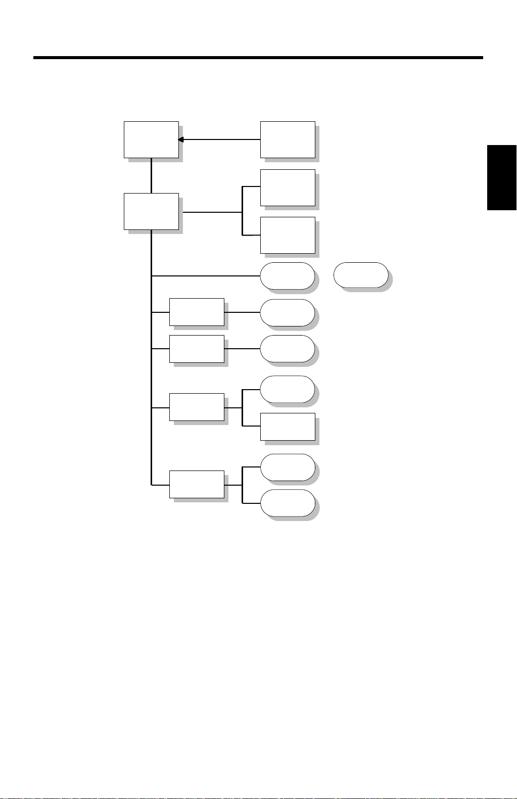
4.3 SERVICE MODE
4.3.1 OVERVIEW
Password
A special key combination is required to enter this menu to prevent customers from
using this menu.
Serv ice Men u Map
SERVICE
[#Enter]
Incorrect
password
[#Enter]
Exits menu and
prints list
[#Enter]
Exits menu and
prints chart
[#Enter]
Clears fuser
counter and exits
menu
ENTER PASSWORD
Enter password
Correct password
PRINT SERVICE
INFORMATION LIST
[
] key
VVVV/WWWW
PRINT COLOR CHART
] key
[
VVVV/WWWW
CLEAR FUSE CTR
Tables
Service
Entering the Service Menu
While the LCD displays “ENTER PASSWORD”, press the
at the same time.
To exit this menu, turn off the machine.
4-15
G024C502.WMF
[ON LINE]
and
[ ]
keys
Page 29

SERVICE MODE 12 May, 1999
4.3.2 PRINT SERVICE INFORMATION LIST
The table below explains the contents of the engine maintenance list printout. The
controller obtains the data from the engine (MCU).
Item Description
MCU Firmware
version
Density Settings Customers can adjust the toner density via the maintenance menu.
Margin Settings Customers can adjust side-to-side registration from the optional tray
Total Indicates the total number of printouts. The counter is incremented
Color Print Counter value for printouts in color mode.
B/W color Counter value for printouts in monochrome mode.
PCU PCU replacement is indicated when this value reaches 60000. This
Fusing unit
Counters
Fusing Unit
Replacement
A3/DLT, A4/LT,
LG, B4 and etc.
Size counter
Feed Jam,
Transfer Jam
and Eject Jam
SC Number of SCs
SC Error History The most recent 3 SC codes.
Jam History The most recent 10 jam codes and the total counter value at the time.
Process-control error
History
ID sensor PWM
setting
The MCU board firmware version number.
Adjusted values are stored in the NVRAM on the MCU.
with the Maintenance Menu. In additi on, le ading edge registration can
be done with engine SP mode (1. Margin). These values are stored in
the NVRAM on the MCU.
when the paper exit sensor detects paper exit completion (regardless
of paper size, type, and mono/color mode).
value increases by 4 in color mode printing and by 1 in black mode
printing. When printing in A3/DLT, double counting occurs.
Fusing unit replacement is indicated when this value reaches to 60000.
This counter increases by 2 for A3/DLT size printing and by 1 for
printing in other sizes.
Number of fusing unit resets made with service mode.
Number of sheets of each size of paper that passed the exit sensor.
Number of paper jams in each section.
000: Paper cassette
001: Paper feed path
002: Paper exit
The most recent 3 errors during process control and the total counter
value at the time.
Not all of the errors are indicated as SC errors.
The value set with engine SP mode, 9: ID Sensor PWM.
4-16
Page 30

12 May, 1999 SERVICE TABLES AND PROCEDURES
4.3.3 PRINT COLOR CHART
This prints a color test chart, so that the image quality can be tested for all colors at
various densities. This chart prints on A4/LTR or A3/DLT size paper or larger.
4.3.4 CLEAR FUSER CTR
This mode resets the fusing unit counter (this counter is in the NVRAM on the MCU
board). Use this mode after replacing the fusing unit.
Tables
Service
4-17
Page 31

12 May, 1999
5. PERIODIC MAINTENANCE
Refer to Section 5 (Periodic Maintenance) in the engine service manual.
Refer to Section 4 (Service Tables and Procedures – Service Mode – Clear Fuser
Ctr) for how to clear the fusing unit counter after fusing unit replacement.
Preventive
Maintenance
5-1
Page 32

12 May, 1999 REPLACEMENT AND ADJUSTMENT
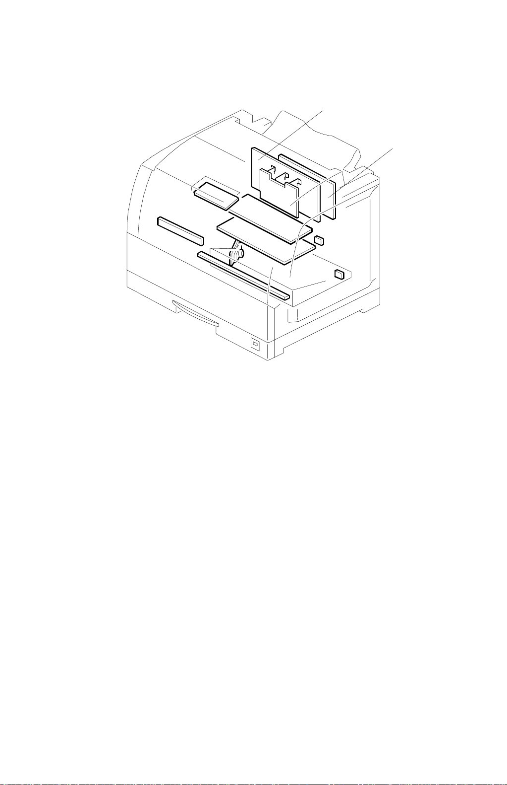
6. REPLACEMENT AND ADJUSTMENT
6.1 CONTROLLER BOARD REPLACEMENT
[A]
G024R551.WMF
[C]
[D]
[E]
[B]
G024R552.WMF
[F]
G024R553.WMF
NOTE:
Print the “Configuration Sheet” (refer to the Operation Manual) prior to
removing the controller board, because the NVRAMs cannot be
exchanged. The user must restore this data manually.
1. Remove the controller cover [A] (6 screws).
2. Remove the tray cover [B] (2 screws).
3. Remove the temperature/humidity sensor cover (1 screw) and sensor [C], (1
screw, 1 connector [D]).
4. Remove the controller bracket [E] (5 screws).
5. Remove the controller board [F] (6 screws).
After replacing the controller board, make sure that the brand name (and MAC
address if required by the user) stored in the machine is correct. (See Section 4
“Service Tables and Procedures - Boot ROM Menu”.)
Adjustment
Replacement
6-1
Page 33

12 May, 1999 TYPES OF PROBLEMS
7. TROUBLESHOOTING
7.1 TYPES OF PROBLEMS
The problems can be classified as follows:
•
Printer-side Print Settings
Operation
Hardware
•
Printer-side Initial Settings
•
Host-side Application Settings
•
Faulty Engine
•
Faulty Controller
•
Hardware Limitations
•
Main Unit
•
Option
•
Consumables
•
Main Unit
•
Option
Software
Operating
conditions
•
Bug in Controller ROM
•
Bug in Emulation Module Software
•
Controller Limitations
•
Bug in Host-side Application
•
Host-side Application Limitations
•
Environment (power, temperature and humidity,
dust, noise, vibration)
•
Consumables
G024O014.WMF
Trouble-
shooting
7-1
Page 34

TROUBLESHOOTING PROCEDURE 12 May, 1999
7.2 TROUBLESHOOTING PROCEDURE
7.2.1 HARDWARE TESTS
1. Start-up diagnostics
Turn on the power and check whether the LCD displays an error code.
2. Custom diagnostic test
See “Section 4.1 Diagnostics Mode” in this manual for the procedure.
3. Checking the configuration page output.
Print out from the user menu.
4. Connectivity test
Make a test print from a computer.
•
Check that the correct cable is used (and connected properly).
•
Check the cable wire continuity
•
Check the cable length (Is it too long?).
•
Do not connect the printer to the computer through a printer selector switch
– connect the printer to the computer directly.
7.2.2 OPERATION-RELATED TESTS
Check the print conditions and initial settings.
Check the printer settings against the application settings. Check whether the
current settings match the settings on the configuration page that the customer
keeps.
Ask the customer to print a configuration page at some time when the controller is
working normally, and keep it for reference.
7-2
Page 35

12 May, 1999 TROUBLESHOOTING PROCEDURE
7.2.3 SOFTWARE-RELATED TESTS
Obtain information about the following:
•
PC model
•
OS type and version
•
Configuration page
•
Application software used, and the version
•
Data file being printed when the problem occurred (if obtainable)
•
Sample printouts when the error occurred and when the printer is normal
•
Detailed operating procedure
•
Controller version (bootstrap, system code and boot code)
•
Engine firmware version
•
Printer driver version
7-3
Trouble-
shooting
Page 36

ERROR MESSAGES 12 May, 1999
7.3 ERROR MESSAGES
7.3.1 OVERVIEW
The error messages for this unit are classified as follows:
1. Controller Diagno s tics Errors
Errors detected while the unit performs start-up diagnostics/custom diagnostics
on the controller hardware.
2. Engine User Errors (Cautionary)
Errors that do not require user intervention to continue printing (the printer can
still communicate with the PC over the interface). However, for the best printing
quality, the user should correct the problem as soon as possible.
3. Engine Service Codes (SCs)
Severe errors that cause the unit to stop printing, requiring a technician to fix
the problem before printing again.
7-4
Page 37

12 May, 1999 ERROR MESSAGES
7.3.2 CONTROLLER DIAGNOSTICS ERRORS
When a controller diagnostics error occurs, the first line of the operation panel LCD
displays the name of the test that detected the error.
The second line contains a 6-digit code following “TYPE ID” that gives error details
for designers to use when debugging.
IDE Test Error
Code Description Location
0x1001 IDE controller problems IDE chip
0x1002
0x1003 Unexpected return values of function calls Chip or HDD
Ethernet Test Error
Code Description Location
0x400 Cannot find Ethernet chip
0x401 Internal register test failed
0x2001 Internal error
0x2002 Chip error
0x2003 Receive error
0x2004 Transmit error
0x2005 No net activity
0x2006 Fatal summary
0x2007 Lost carrier
0x2008 Transmit flow error
0x2009 No chip
0x2010 Interrupt error
0x2011 Low receive
Hard disk problems or cable connection
problem
HDD or cable
Replace the controller.
MEM Test Error
Code Description Location
0x0300 Bad memory information
0x0301 Bad memory
0x0302 Ground bounce test failed
Replace the controller.
VX Test Error
Code Description Location
0x1801 Bad VX chip; registers cannot be
programmed correctly
7-5
Replace the controller.
Trouble-
shooting
Page 38

ERROR MESSAGES 12 May, 1999
Boot ROM Test Error
Code Description Location
0x1811 Internal error
0x1812 Unknown boot flash type
0x1813 Incorrect chip installed
0x1814 Successive reads return different values
0x1815 Checksum failed for boot ROM
0x1816 Erasing boot ROM not completed
successfully.
0x1817 Data written to the boot ROM cannot be
verified correctly.
0x1818
0x1819 Parameter blocks cannot be overwritten
Boot ROM write test not performed since
parameter blocks are not empty
Replace the controller.
EFIDIMM Test Error
Code Description Location
0x1820 System DIMM not found
0x1821 Cannot read from system DIMM properly,
or system DIMM located in an incorrect
slot
0x1823 Checksum for system code failed.
0x1824 Checksum for file system failed
0x1825
Checksum for system code and file
system failed.
Replace the controller.
I2CEEPROM Test Error
Code Description Location
0x1100 Read error at I2CEEPROM Replace the controller.
7-6
Page 39

12 May, 1999 ERROR MESSAGES
7.3.3 ENGINE USER ERRORS (CAUTIONARY)
Refer to the Troubleshooting section in the Operating Instructions.
7.3.4 ENGINE SERVICE CODES
Refer to the Troubleshooting section in the Engine Service Manual.
7-7
Trouble-
shooting
 Loading...