

Page 1

FRESA WIN+
(Machine Code: G047/G048)
SERVICE MANUAL
[Engine]
Page 2

IMPORTANT SAFETY NOTICES
PHYSICAL INJURY PREVENTION
1. Before disassembling or assembling parts of the printer and peripherals,
make sure that the power cord is unplugged.
2. The wall outlet should be near the printer and easily accessible.
3. Note that some printer components are supplied with electrical voltage even
if the main switch is turned off.
4. If an adjustment or operation check must be made requiring the removal or
opening of the exterior covers while the main switch is on, keep hands away
from electrified or mechanically driven components.
5. The printer drives some of its components when it completes the warm-up
period. Keep hands away from mechanical and electrical components when
the printer starts operation.
6. The interior and metal parts for the fusing unit become extremely hot while
the printer is operating. Do NOT touch these components with bare hands.
HEALTH SAFETY CONDITIONS
1. Never operate the printer without ozone filters installed.
2. Always replace the ozone filters with the specified replacement at the
specified maintenance intervals.
3. Toner is non-toxic, but if it gets in your eyes by accident, it may cause
temporary eye discomfort. Remove it with eye drops or flush eyes with
water. If this is unsuccessful, get medical attention immediately.
SAFETY AND ECOLOGICAL NOTES FOR DISPOSAL
1. Do NOT incinerate toner cartridges, development toner magazine (DTM) or
used toner. Toner dust may ignite suddenly when exposed to an open flame.
2. Dispose of used toner bottle and photoconductor unit (PCU) in accordance
with local regulations. (These are non-toxic supplies.)
3. Dispose of replaced parts in accordance with local regulations.
Page 3
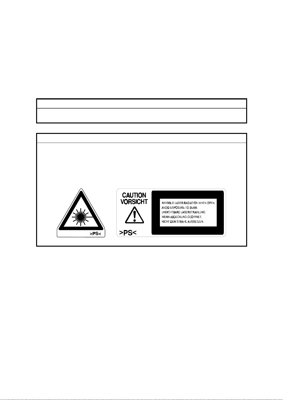
LASER SAFETY
The Center for Devices and Radiological Health (CDRH) prohibits the repair of
laser-based optical units in the field. The optical unit can only be repaired in a
factory or at a location with the requisite equipment. The laser subsystem is only
replaceable in the field by a qualified Customer Engineer. The laser chassis is not
field repairable. Customer engineers are therefore directed to return all chassis and
laser subsystems to the factory or service depot when the optical subsystem
requires replacement.
WARNING
Use of controls, or adjustment, or performance of procedures other than
those specified in this manual may result in hazardous radiation exposure.
WARNING
WARNING: Turn off the main switch before attempting any of the
procedures in the Laser Unit section. Laser beams can
seriously damage your eyes.
CAUTION MARKING:
Page 4

TABLE OF CONTENTS
1. OVERALL MACHINE INFORMAT ION........................................ 1-1
1.1 SPECIFICATIONS.....................................................................................1-1
1.2 MECHANICAL OVERVIEW.......................................................................1-3
1.3 MAIN UNIT LAYOUT.................................................................................1-3
1.4 SYSTEM BLOCK.......................................................................................1-5
1.4.1 BLOCK DIAGRAM............................................................................1-5
2. DETAILED SECTION DESCRIPTIONS ...................................... 2-1
2.1 DIFFERENT POINTS FROM BASE MODEL (G024)................................2-1
2.1.1 OVERVIEW......................................................................................2-1
2.1.2 FUSING UNIT...................................................................................2-2
2.1.3 OPTICAL UNIT.................................................................................2-2
2.1.4 PAPER FEEDING AND REGISTRATION........................................2-3
2.1.5 PROCESS CONTROL......................................................................2-3
2.1.6 ELECTRICAL COMPONENTS.........................................................2-3
2.2 DUPLEX PRINTING (AUTO-DUPLEX MODEL ONLY).............................2-4
2.2.1 OVERVIEW......................................................................................2-4
Layout...................................................................................................2-4
Electrical Components..........................................................................2-5
2.2.2 EXIT UNIT........................................................................................2-7
Driving Mechanism...............................................................................2-7
Junction Gate........................................................................................2-7
Exit Cover Open Detection...................................................................2-8
2.2.3 VERTICAL TRANSPORT UNIT........................................................2-9
Driving Mechanism...............................................................................2-9
Paper Feed Detection...........................................................................2-9
Vertical Transport Unit Cover Open Detection....................................2-10
2.2.4 DUPLEX UNIT................................................................................2-11
Driving Mechanism.............................................................................2-11
Reverse Mechanism...........................................................................2-11
Jogging Mechanism............................................................................ 2-12
Feed-out .............................................................................................2-12
Reverse Tray Detection......................................................................2-12
2.2.5 INTERLEAF....................................................................................2-13
Paper Path for Duplex Printing ...........................................................2-13
Print Order for Duplex Black & White Printing.....................................2-14
Print Order for Duplex Color Printing..................................................2-14
3. INSTALLATION PROCEDURE................................................... 3-1
i
Page 5

4. SP MODE.................................................................................... 4-1
4.1 OVERVIEW...............................................................................................4-1
4.2 ENGINE SP MODE...................................................................................4-1
4.2.1 OVERVIEW......................................................................................4-1
To enter and exit engine SP mode .......................................................4-1
Outline of the engine SP mode functions..............................................4-1
4.2.2 MENU OPERATION/DISPLAY.........................................................4-2
4.2.3 MARGIN (REGISTRATION ADJUSTMENT)....................................4-2
4.2.4 PARAMETER...................................................................................4-3
4.2.5 CLEAR MEMORY.............................................................................4-3
4.2.6 SENSOR CHECK.............................................................................4-4
4.2.7 NIP WIDTH.......................................................................................4-5
4.2.8 RESET SC........................................................................................4-5
4.2.9 PROCESS CTRL..............................................................................4-6
4.2.10 TEST PRINT...................................................................................4-6
4.2.11 ID SENSOR PWM (PULSE WIDTH MODULATION)......................4-6
4.2.12 IMAGE ADJUST.............................................................................4-6
4.2.13 OUTPUT CHECK...........................................................................4-7
4.2.14 HIGHLIGHT ADJUSTMENT...........................................................4-8
4.2.15 LUB_INTERVAL
(BELT LUBRICATION INTERVAL ADJUSTMENT)........................4-8
4.2.16 PRIMARY BIAS ADJUSTMENT.....................................................4-9
5. PREVENTIVE MAINTENANCE................................................... 5-1
5.1 PM TASKS ................................................................................................5-1
5.1.1 REPLACEMENT...............................................................................5-1
5.1.2 CLEANING.......................................................................................5-1
5.1.3 INSPECTION....................................................................................5-1
5.2 PM TABLE.................................................................................................5-2
5.2.1 MAIN UNIT.......................................................................................5-2
5.2.2 OPTIONAL PAPER FEED UNIT ......................................................5-2
6. REPLACEMENT AND ADJUSTMENT
(AUTO-DUPLEX MODEL)........................................................... 6-1
6.1 EXTERIOR................................................................................................6-1
6.1.1 TOP OVER.......................................................................................6-1
6.2 PAPER EXIT UNIT....................................................................................6-2
6.2.1 UPPER COVER ...............................................................................6-2
6.2.2 LOWER COVER...............................................................................6-2
6.2.3 PAPER EXIT UNIT...........................................................................6-3
6.2.4 JUNCTION GATE SOLENOID.........................................................6-4
6.3 VERTICAL TRANSPORT UNIT.................................................................6-5
6.3.1 VERTICAL TRANSPORT UNIT COVER..........................................6-5
6.3.2 UPPER, LEFT AND RIGHT SIDE COVER.......................................6-5
6.3.3 VERTICAL UNIT SENSOR...............................................................6-6
6.3.4 VERTICAL TRANSPORT MOTOR...................................................6-6
ii
Page 6

6.3.5 VERTICAL TRANSPORT UNIT........................................................6-7
6.4 DUPLEX UNIT...........................................................................................6-8
6.4.1 DUPLEX TRAY.................................................................................6-8
6.4.2 REVERSE ROLLER.........................................................................6-9
6.4.3 DUPLEX FEED MOTOR/REVERSE MOTOR................................6-10
6.4.4 DUPLEX FEED SENSOR...............................................................6-10
6.4.5 JOGER HOME POSITION SENSOR.............................................6-11
6.4.6 JOGGER MOTOR/REVERSE SOLENOID.....................................6-12
6.4.7 REVERSE SENSOR......................................................................6-13
6.4.8 TEMPERATURE/HUMIDITY SENSOR..........................................6-13
6.4.9 RELAY MOTOR/RELAY ROLLER..................................................6-14
6.5 FUSING SECTION..................................................................................6-15
6.5.1 FUSING UNIT.................................................................................6-15
6.6 LASER SECTION....................................................................................6-16
6.6.1 CAUTION DECAL LOCATIONS.....................................................6-16
6.6.2 OPTICAL HAUSING UNIT..............................................................6-17
6.7 ELECTRICAL COMPONENTS................................................................6-18
6.7.1 CONTROLLER BOARD.................................................................6-18
6.7.2 DUPLEX DC SUPPLY UNIT...........................................................6-19
6.7.3 POWER SUPPLY UNIT..................................................................6-20
6.7.4 HIGH VOLTAGE SUPPLY UNIT....................................................6-21
6.7.5 MCU ...............................................................................................6-22
6.7.6 DUPLEX DRIVER BOARD.............................................................6-22
7. TROUBLESHOOTING ................................................................ 7-1
7.1 SC TABLES...............................................................................................7-1
7.1.1 TYPES OF SERVICE CALL.............................................................7-1
Fusing Unit SC Errors...........................................................................7-1
7.1.2 SC ERROR LIST..............................................................................7-2
7.1.3 PROCESS CONTRL ERROR LIST..................................................7-6
7.2 USER ERROR LIST...................................................................................7-8
iii
Page 7

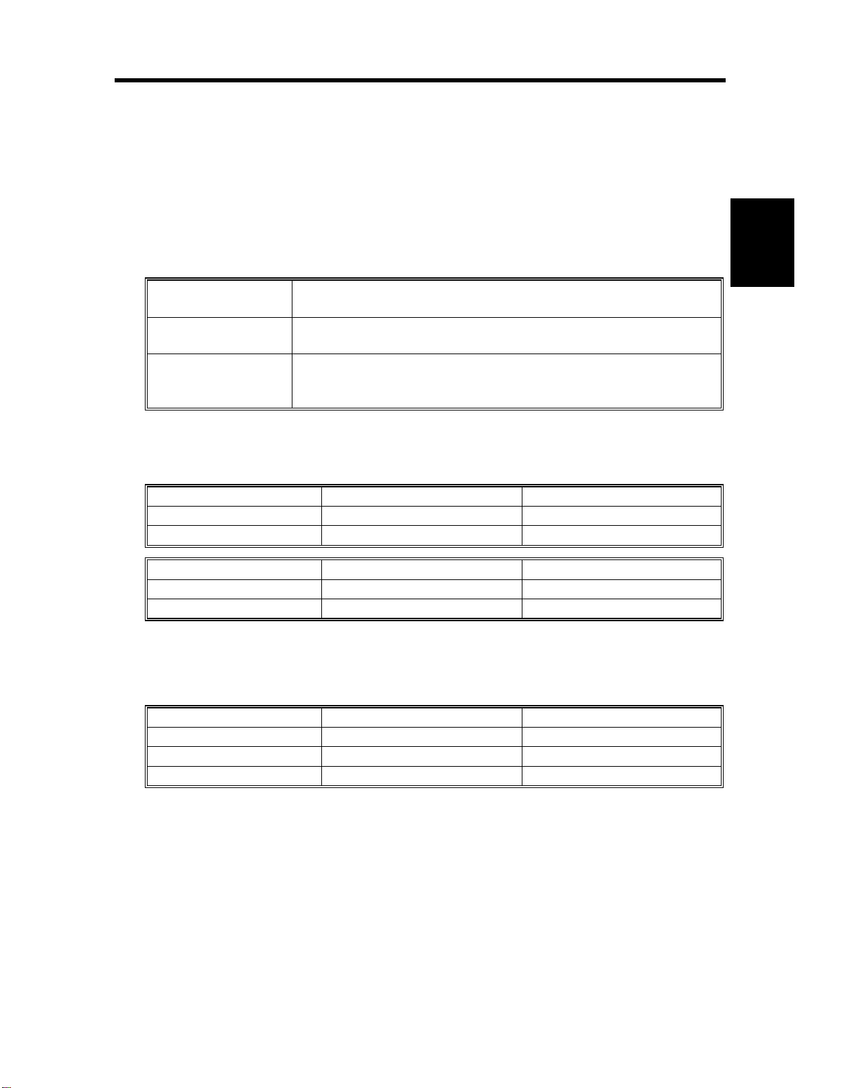
30 June 2000 SPECIFICATIONS
1. OVERALL MACHINE INFORMATION
1.1 SPECIFICATIONS
Configuration Desk top
Print Process Dry electrostatic transfer system
Resolution 600 dpi
Paper Size Standard tray
Short edge feed (SEF):
A3, 11" x 17", 8
8
" x 13", 8
1/4
Long edge feed (LEF):
A4, 8
5
1/2
1/2
" x 8
" x 11", 7
")
1/2
By-pass feed tray*
Short edge feed:
A3, A6, B4 JIS, B6 JIS, 12" x 18",11" x 17",
8
" x 14", 8" x 13", 8
1/2
Long edge feed:
A4, A5, B5 JIS, 8
Custom size paper (Length: 148 to 457.2 mm,
Width: 90 to 297 mm)
" x 14", Others* (B4 JIS, 8" x 13",
1/2
" x 13")
1/2
" x 10
1/4
1/2
1/2
" x 13", 8
1/4
" x 11", 5
", Others* (B5 JIS, A5,
" x 13"
1/2
1/2
" x 8
1/2
", 7
1/4
" x 10
1/2
Overall
Information
"
* Specify the paper size with the system menu (at the
operation panel by the user).
Paper Weight Standard and optional trays: 64 to 105 g/m2 (17 to 28 lbs.)
By-pass feed tray: 64 to 160 g/
Plain paper mode: 64 to 105 g/m
m2 (17 lbs to 43 lbs
2
)
Thick paper mode: 105 to 160 g/m2, adhesive labels
OHP transparency mode: OHP transparencies
First Printout Time Color: Less than 26 seconds (A4 A4/8
Monochrome: Less than 13 seconds (A4 A4/8
" x 11" LEF)
1/2
1/2
" x 11"
LEF)
Print Speed Simplex prints
Color: 6 ppm (A4/8
Monochrome: 24 ppm (A4/8
" x 11" LEF)
1/2
" x 11" LEF)
1/2
Duplex prints
Warm-up Time
Color: 5.5 ppm (A4/8
Monochrome: 21.7 ppm (A4/8
Less than 380 seconds (at 23°C/73°F)
" x 11" LEF)
1/2
" x 11" LEF)
1/2
Paper Capacity Standard tray: 250 sheets (80 g/m2, 20 lbs.)
By-pass feed tray: 50 sheets (80 g/m2, 20 lbs.)
Optional trays: 500 sheets (80 g/m2, 20 lbs.)
1-1
Page 8

SPECIFICATIONS 30 June 2000
Paper Output
Capacity
250 sheets (A4/8
" x 11" or less)
1/2
100 sheets (More than A4/8
" x 11")
1/2
Output Method Face down
Power Supply 120 V, 60 Hz, 10 A
220 to 240 V, 50/60 Hz, 5.2 A
Power Consumption Maximum: Less than 1,200 W
Average during printing: Less than 750 W
Stand-by mode: Less than 150 W
Energy saver mode: Less than 45 W
Noise Emission
(Sound Power Level)
Stand-by: Less than 43 dB
Operating: Less than 65 dB
Dimensions Simplex model (G047)
660 x 575 x 475 mm (26” x 22.6” x 18.7”)
(without paper tray)
Auto duplex model (G048)
660 x 652 x 610 mm (26” x 25.7” x 24”)
(without paper tray)
Weight Simplex model (G047)Approximately 62 kg (136.7 lbs.)
(including consumables)
Auto-Duplex model (G048)
Approximately 82 kg (180.8 lbs.)
(including consumables)
Option Paper Feed Unit Type 305 (Paper Tray Unit) – up to two of
these units can be installed
1-2
Page 9
30 June 2000 MECHANICAL OVERVIEW
1.2 MECHANICAL OVERVIEW
Same as base model (G024)
Refer to the Section 1-2 of base model manual.
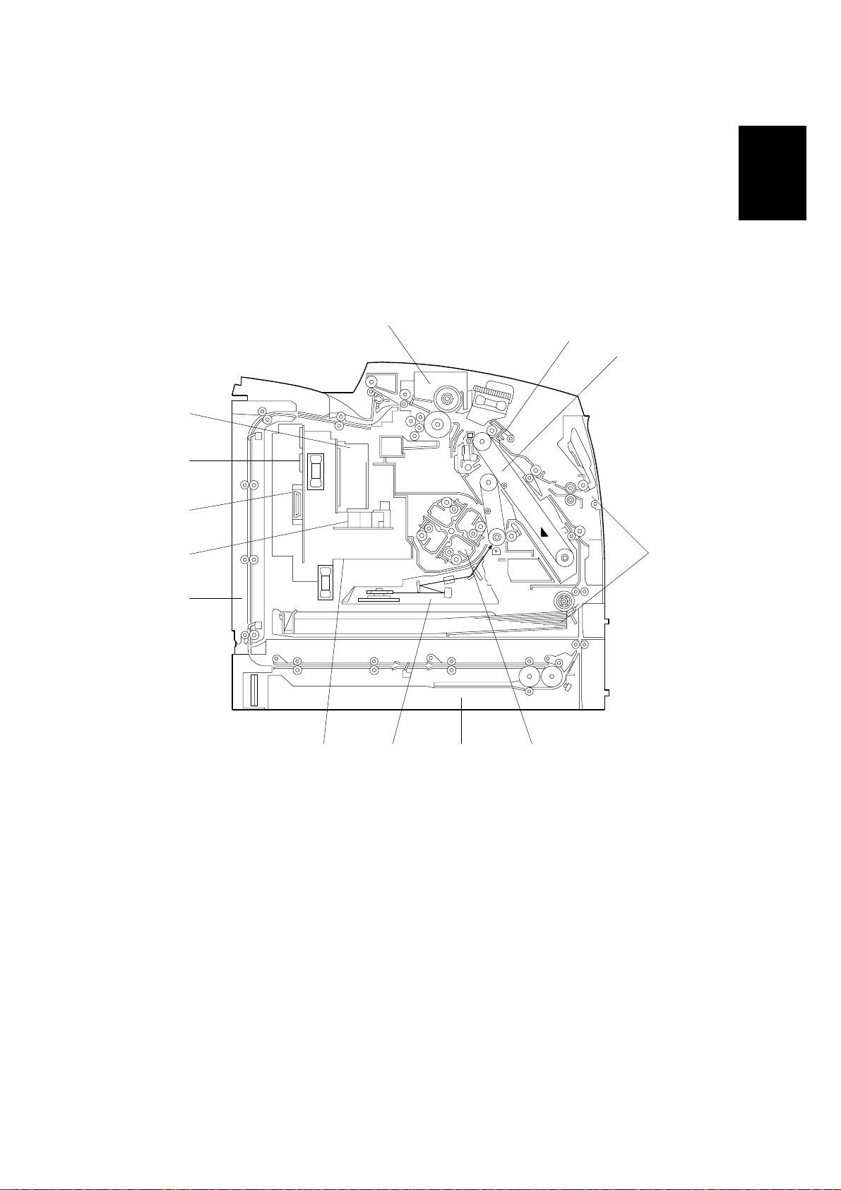
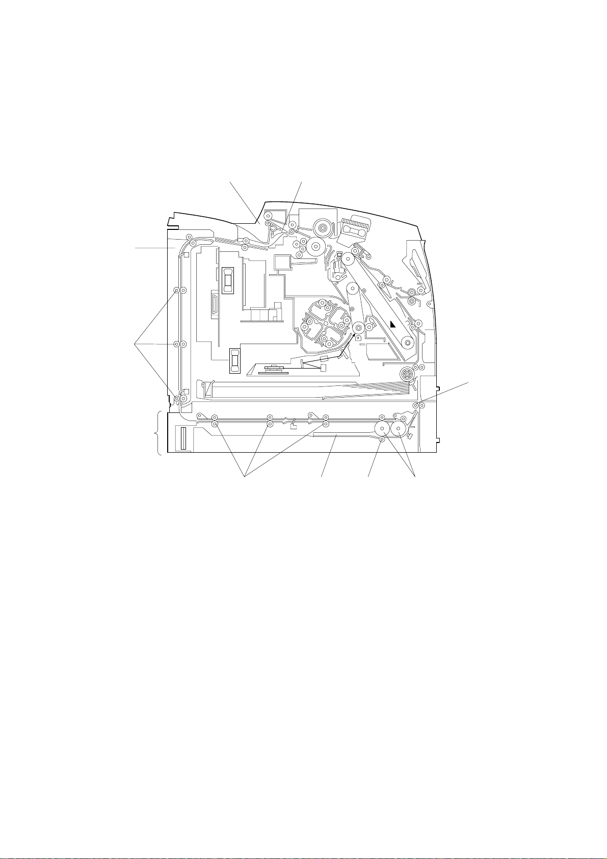
1.3 MAIN UNIT LAYOUT
13
1
2
12
11
Overall
Information
10
9
8
1. Paper Transfer Unit
2. Photoconductor Unit (PCU)
3. Paper Tray/Paper Feed Mechanism
4. Development Unit (DTM)
5. Duplex Unit
6. Optical Housing Unit
7. Main Control Unit (MCU)
5
467
G048V101.WMF
8. Vertical Transport Unit
9. High Voltage Supply Unit
10. DC Supply Unit
11. Controller Board
12. Power Supply Unit
13. Fusing Unit
3
1-3
Page 10

MAIN UNIT LAYOUT 30 June 2000
(1) Optical Housing Unit
• Optical system: 6-sided polygon mirror, F-theta mirror, BTL
• Resolution: 600 dpi
• Modulation method: PM+PWM
(2) MCU
• CPU: XC68334 GFC16
• Engine system control
• Process control
• Video interface
(3) Vertical Transport Unit (Auto-duplex Model Only)
• Paper feeding for duplex printing by rollers
(4) High Voltage Supply Unit
• Constant current: Paper transfer, charge corona wire
• Constant voltage: Charge corona grid, belt transfer, supply roller,
development blade
(5) DC Supply Unit (Auto-duplex Model Only)
• Outputs: +24 VDC supply for duplex unit
(6) Controller Board
• Host interface
• Video interface
• Image processing
• Operation panel control
(7) Power Supply Unit
• Outputs: +5 VDC, +24 VDC, 120/230 VAC
(8) Fusing Unit
• Fusing method: Hot roller method
• Oil application: Application roller method
• Cleaning: Cleaning roller method
• Temperature detection: Thermistor
• Safety precaution: Thermofuse
(9) Paper Transfer Unit
• Transfer: Transfer rol l er met hod
(10) PCU
A unit consisting of the OPC belt and the primary (belt) transfer section.
• OPC belt: 93-mm diameter
• Charging: Single scorotron charge corona wire
• Primary transfer: Transfer belt
• Cleaning: Counter blade
• Lubricant: Zinc stearate
1-4
Page 11
30 June 2000 SYSTEM BLOCK
(11) Tray/Transport
• Standard tray: Universal tray, friction pad separation
By-pass tray: FRR method
(12) Development Unit
• Development method: Monocomponent non-magnetic toner
• Development unit changeover: Revolver method
• Toner replenishment: DTM change
(13) Duplex Unit
• Stack-less
• Paper side edge jogging
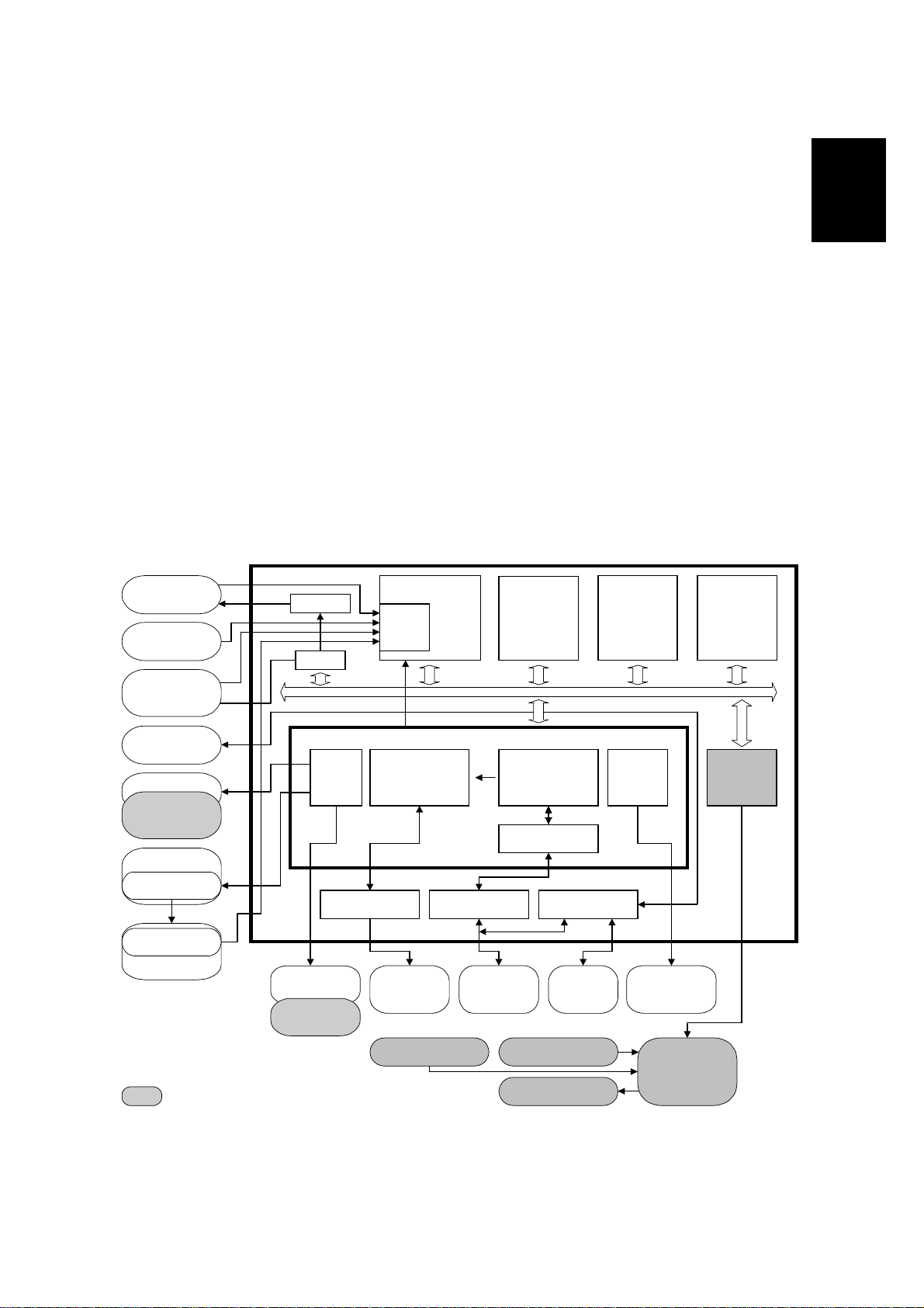
1.4 SYSTEM BLOCK
1.4.1 BLOCK DIAGRAM
ADC
CPU
ROM
ID Sensor
Humidity
Sensor
High Voltage
Supply Board
D/A
PWM
Overall
Information
NVRAM DRAM
IC Card
Sensors
Vertical
Transport
Sensor
PSU
Fusing
Control
I/O
AMDG
MCU
Thermistor
Fusing Unit
: Additional components on deplex model (G048)
Solenoids
Clutches
Interchange
Solenoids
LD
Modulation
Control
DC Supply Unit
ASIC
Video I/FGAVD/PLLC
Printer
Controller
Pattern
Generation
FIFO
Selector
Operation
Panel
Sensor
Motor Solenoids
Motor
Control
Revolver
Main Motor
PCU Motor
Expander
DDB
G048V554.WMF
1-5
Page 12
30 June 2000 DIFFERENT POINTS FROM BASE MODEL (G024)
2. DETAILED SECTION DESCRIPTIONS
2.1 DIFFERENT POINTS FROM BASE MODEL (G024)
2.1.1 OVERVIEW
The following points are different from the base model (G024).
1. Duplex printing
The following units were added to the Auto-duplex model (G048)
Paper Exit Unit Switching the paper path to the exit or to the duplex unit after
fusing.
Vertical Transport
Unit
Duplex Unit This unit is located at the bottom of the main-body. In this
Interleaf control is used for this model to increase the printing speed.
For duplex printing, feeding a sheet to duplex unit after fusing.
This unit is located behind the main-body.
unit, a sheet is turned, jogged and then fed to the main-body
again. Sheets are fed into this unit one-by-one.
Detailed
Descriptions
2. Printing Speed
Printing Speed G047/G048 Base Model (G024)
Black & White mode 24 ppm 17 ppm
Color mode 6 ppm 5 ppm
First Print G047/G048 Base Model (G024)
Black & White mode 13 sec. 14 sec.
Color mode 26 sec. 30 sec.
3. Image Quality Improvement
Increasing the line frequency in photograph and text mode improves the quality
of the image. A new laser optical unit is used to increase the line frequency.
Line Frequency G047/G048 Base Model (G024)
Photograph 180 lpi 106 lpi
Graphics 106 lpi 106 lpi
Text 268 lpi 211 lpi
2-1
Page 13

DIFFERENT POINTS FROM BASE MODEL (G024) 30 June 2000
2.1.2 FUSING UNIT
The followings differ from the base model (G024) in the Fusing unit.
1. Pressure Roller
For the duplex printing, The material used to make the pressure roller was
changed from Teflon to Silicon rubber to improve duplex printing performance.
2. Heat Isolation
To maintain the fusing roller temperature, heat isolation bushings are mounted
between the fusing roller bushing and drive gear.
3. Connector
All of the drawer connectors were replaced with harness connectors.
4. Exit Cover Switch (Auto-duplex model only)
The location of paper exit cover switch was moved to the main-body of the
machine from the fusing unit..
2.1.3 OPTICAL UNIT
The following optical unit ite ms differ from the previous model.
1. Polygonal Mirror Motor
The speed of the polygonal mirror motor was increased to increase the printing
speed.
G047/G048 Base Model (G024)
Paper feed speed 121.54 mm/sec 101.27 mm/sec.
Mirror motor revolution
speed
28,706 rpm 23,922 rpm
2. LD Unit
To improve the image quality, the diameter of the beam was decreased and the
power of the beam was increased.
G047/G048 Base Model (G024)
Diameter of Beam
LD Power 1.91 mW 1.58 mW
69 µm x 76 µm 76 µm x 76 µm
3. Dust Prevention
To prevent the polygonal mirror and polygon mirror motor from collecting dust,
two sponges were added to the optical housing. One is above the polygon
mirror motor and the other is on the side of the housing unit.
2-2
Page 14
30 June 2000 DIFFERENT POINTS FROM BASE MODEL (G024)
2.1.4 PAPER FEEDING AND REGISTRATION
1. Paper size detection of bypass tray
Paper width detection mechanism on the bypass tray is not available.
2. Pick-up roller
The material of pick-up roller is changed to Silicone rubber for duplex printing
from the bypass tray.
2.1.5 PROCESS CONTROL
1. K-DTM Initialization
The image density target level was lowered.
G047/G048 Base Model (G024)
ID on sheet 1.6 1.7
Volume of toner 0.56 mg/cm
2
0.60 mg/cm
2
Detailed
Descriptions
2. Color-DTMs Initialization
The image density target level was changed.
G047/G048 Base Model (G024)
ID on sheet 1.4 1.5
Volume of toner (C) 0.56 mg/cm
Volume of toner (Y) 0.54 mg/cm
Volume of toner (M) 0.62 mg/cm
2
2
2
0.55 mg/cm
0.55 mg/cm
0.60 mg/cm
3. Charge Grid Bias Compensation
Compensation control was changed because the number of lines in photo
mode was changed from 106 to 180.
2.1.6 ELECTRICAL COMPONENTS
1. Main Motor
The main motor was changed to increase the print speed.
The PCU motor was not changed but the clock rate was changed.
2. MCU
The MCU was changed to improve the efficiency of duplex printing by adding
new electrical components.
2
2
2
3. PSU
A different PCU was used to increase the current level.
A DC supply unit was added for Auto-duplex models only.
2-3
Page 15
DUPLEX PRINTING (AUTO-DUPLEX MODEL ONLY) 30 June 2000
2.2 DUPLEX PRINTING (AUTO-DUPLEX MODEL ONLY)
2.2.1 OVERVIEW
Layout
10
9
8
7
1
2
1. Junction Gate
2. Relay Roller
3. Duplex Roller
4. Duplex Pick-up Roller
5. Jogger Fence
56
G048D101.WMF
6. Duplex Feed Roller
7. Duplex Unit
8. Vertical Transport Roller
9. Vertical Transport Unit
10. Exit Unit
34
2-4
Page 16
30 June 2000 DUPLEX PRINTING (AUTO-DUPLEX MODEL ONLY)
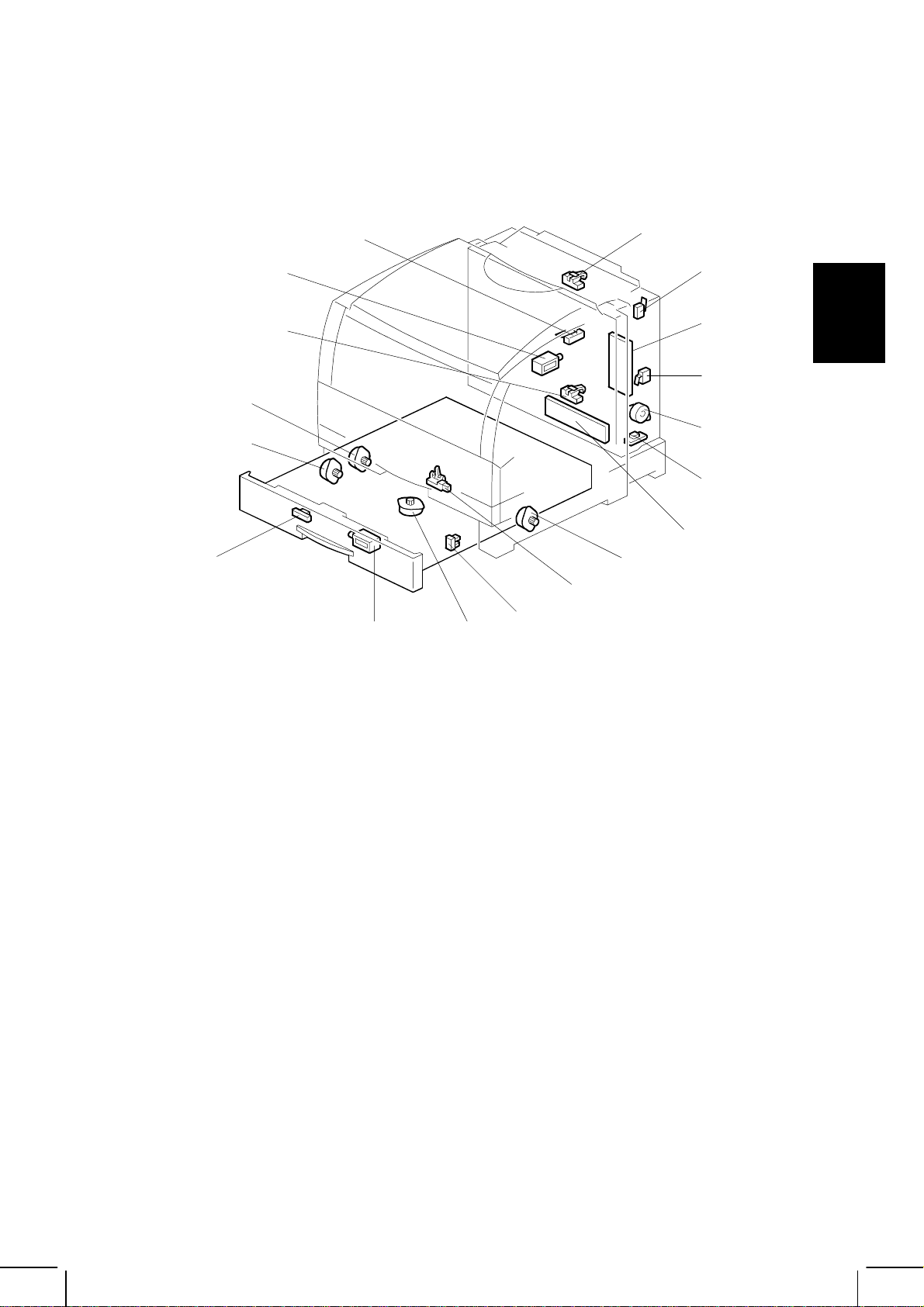
Electrical Components
13
15
14
17
16
18
12
11
10
1
8
9
G048D103.WMF
2
3
Detailed
Descriptions
4
5
6
7
1. Vertical Transport Entrance Sensor
2. Vertical Transport Cover Switch
3. Duplex DC Supply Unit
4. Vertical Transport Unit Switch
5. Vertical Transport Motor
6. Temp./Hum. Sensor
7. Duplex Driver Board
8. Relay Motor
9. Duplex Feed Sensor
10. Jogger HP Sensor
11. Jogger Motor
12. Reverse Solenoid
13. Reverse Sensor
14. Duplex Reverse Motor
15. Duplex Feed Motor
16. Vertical Transport Exit Sensor
17. Junction Gate Solenoid
18. Exit Cover Switch
Exit Unit
- A solenoid moves the junction gate.
- A micro-switch detects if the cover is open.
Vertical Transport Unit
- The vertical transport rollers driven by the vertical transport motor feed paper
to the duplex unit.
- Two sensors detect paper fed in the entrance and out the exit of the unit.
- Two micro-switches detect whether the vertical transport unit and cover are
open.
2-5
Page 17

DUPLEX PRINTING (AUTO-DUPLEX MODEL ONLY) 30 June 2000
Duplex Unit
- The duplex, duplex transport and duplex pick-up rollers reverse the paper in
the unit.
- The jogger fence prepares to feed paper into the main body after reversing it.
- The duplex, duplex pick-up, and relay rollers feed paper into the main body for
reverse side printing.
- The duplex feed sensor and reverse sensor detect paper.
2-6
Page 18
30 June 2000 DUPLEX PRINTING (AUTO-DUPLEX MODEL ONLY)
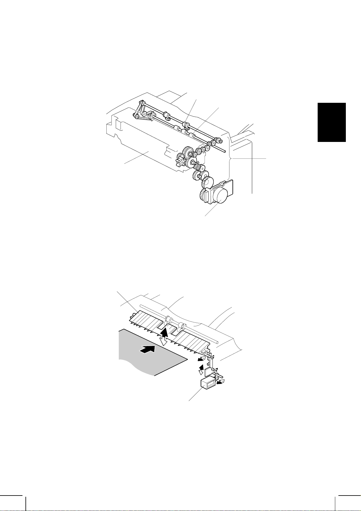
2.2.2 EXIT UNIT
Driving Mechanism
[D]
[E]
Detailed
Descriptions
[A]
[B]
[C]
G048D002.WMF
The fusing unit [A] and drive gears [B], powered by the main motor [C], drive the
feed and exit rollers [D and E].
Junction Gate
[A]
[B]
G048D001.WMF
The Junction gate [A] is located at the entrance of exit unit. Paper is fed to the exit
tray or to the vertical transport unit by this gate. This gate is driven by solenoid [B].
When this solenoid activates, the paper is fed into the vertical transport unit.
2-7
Page 19
DUPLEX PRINTING (AUTO-DUPLEX MODEL ONLY) 30 June 2000
Exit Cover Open Detection
[A]
G048D003.WMF
The exit unit cover switch [A] is on the right side of the unit to detect whether the
cover is open. This switch interrupts the 24VDC line to the main control board
(PCB2).
2-8
Page 20
30 June 2000 DUPLEX PRINTING (AUTO-DUPLEX MODEL ONLY)
2.2.3 VERTICAL TRANSPORT UNIT
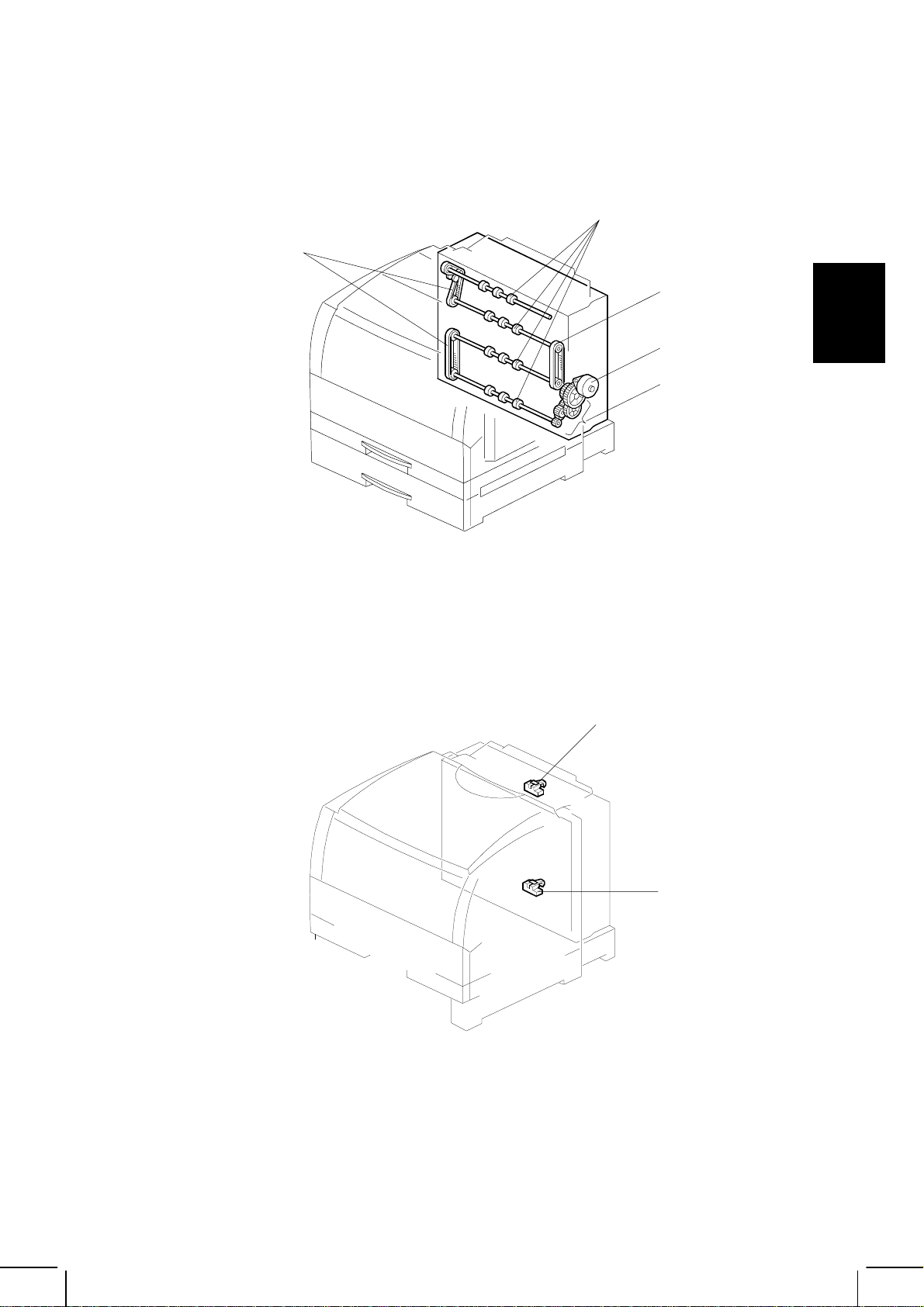
Driving Mechanism
[B]
[D]
[D]
[A]
[C]
G048D501.WMF
The vertical transport motor [A] drives the vertical transport rollers [B] using gears
[C] and timing-belts [D].
Paper Feed Detection
[A]
Detailed
Descriptions
[B]
G048D010.WMF
Two sensors (photo interrupters) detect paper: One is the entrance sensor [A] and
the other is the exit sensor [B].
2-9
Page 21
DUPLEX PRINTING (AUTO-DUPLEX MODEL ONLY) 30 June 2000
Vertical Transport Unit Cover Open Detection
[A]
G048D008.WMF
G048D007.WMF
The interruption of the current for the vertical transport switches [A and B]
determines whether the vertical transport unit or cover is open.
[B]
2-10
Page 22
30 June 2000 DUPLEX PRINTING (AUTO-DUPLEX MODEL ONLY)
2.2.4 DUPLEX UNIT
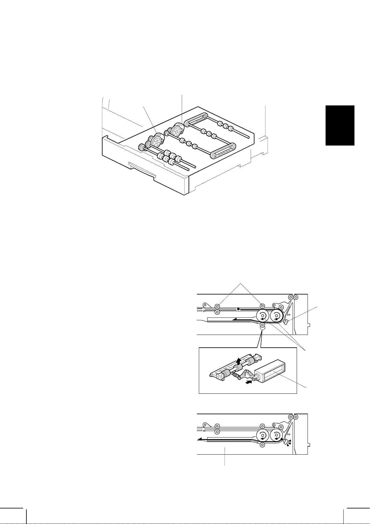
Driving Mechanism
[A]
[B]
G048D502.WMF
Detailed
Descriptions
The duplex feed motor [A] feeds paper from the vertical transport unit up to the
reverse tray. Then the duplex reverse motor [B] feeds the paper from the reverse
tray to the relay rollers.
Reverse Mechanism
[A]
First, paper is fed by the duplex feed
rollers [A] and then by the duplex rollers
[B]. When the reverse sensor [C] detects
the leading edge of paper, the reverse
solenoid [D] activates and paper is fed
into the duplex tray [E].
When the reverse sensor detects the
trailing edge of paper, the reverse
solenoid deactivates.
[B]
[D]
[C]
2-11
[E]
G048D015.WMF
Page 23

DUPLEX PRINTING (AUTO-DUPLEX MODEL ONLY) 30 June 2000
Jogging Mechanism
The standby position distance
between jogger fences [A] is 10mm
wider than the printed paper width
while printing.
After the duplex roller stops, the
jogger motor [B] slides the jogger
fences so that they are 1mm
narrower than the printed paper
width.
After finishing all print job s , the
fences return to the home position,
until the home position sensor [C]
activates.
Feed-out
After jogging the paper, the duplex
roller turns counter-clock wise and the
reverse solenoid activates. This fee ds
paper to the relay roller [A], which is
driven by the relay motor [B].
[A]
[B]
[C]
G048D006.WMF
Reverse Tray Detection
The tray is connected to the duplex
driver board [A] through drawer
connectors [B] when the tray is
pushed into the machine. This
connection is monitored by a loop
back signal to make sure that the tray
is positioned properly in the machine.
[B]
[A]
G048D009.WMF
[A]
[B]
2-12
G048D153.WMF
Page 24

30 June 2000 DUPLEX PRINTING (AUTO-DUPLEX MODEL ONLY)
2.2.5 INTERLEAF
An interleaf mechanism was added to increase duplex printing performance in
black & white print mode. Also, this model only prints face down.
E
D/J
K
C/I
B/H
Detailed
Descriptions
A-1
G
F
A-2
G048D211.WMF
Paper Path for Duplex Printing
A: Paper feed for back-side print ( -1: Standard tray -2: Optional tray)
B: Secondary transfer for back-side print
C: Fusing back-side print
D: Junction
E: Vertical transport
F: Reverse
G: Paper fee d for front-s ide print
H: Secondary transfer for front-side print
I: Fusing for front-side print
J: Junction
K: Paper exit
2-13
Page 25

DUPLEX PRINTING (AUTO-DUPLEX MODEL ONLY) 30 June 2000
Print Order for Duplex Black & White Printing
The following example shows what happens when printing 8 sheets of A4/LTR size
in duplex black & white mode. 4 sheets of A4/LTR size paper can be kept inside
the machine during this print mode.
2
➀➁➂➃
135
➀➄➁➅➂➆
10
4 6 8
12 14
➃➇
7
16
1513119
➇➆➅➄
G048D212.WMF
Print Order for Duplex Color Printing
The following example shows what happens when printing 8 sheets of A4/LTR size
in duplex color mode.
2 sheets print 2 sheets print 2 sheets print
2 4 6 81357
➁➂➃➀➃➂➁➀
G048D214.WMF
2-14
Page 26

30 June 2000 INSTALLATION PROCEDURE
3. INSTALLATION PROCEDURE
Refer to the following materials.
• For the printer: Quick Installation Guide
• For options: Operating Instructions
If the customer has a service contract with a meter click system, set up the counter
with an SP mode as follows:
1. Enter Controller SP mode (se e 4.1.1 ENTERING AND EXITING
CONTROLLER SP MODE in Service manual for controller).
2. Set “Meter Click” from the maintenance menu to the proper mode depending
on the contract type (see 4.1.4 SP MODE DETAILS in Service manual for
controller).
3. Exit SP mode, and then confirm that display of both “Color” and “Black” is 0 by
executing “ Show Counter”
Installation
3-1
Page 27

30 June 2000 OVERVIEW
4. SP MODE
4.1 OVERVIEW
This printer has two SP modes:
1) Engine SP mode
2) Controller SP mode
The controller SP modes are described in the service manual for the controller.
These two modes contain different functions.
4.2 ENGINE SP MODE
4.2.1 OVERVIEW
To enter and exit engine SP mode
Same as the base model (G024)
Outline of the engine SP mode functions
The following table shows differences from the base model (G024)
Menu Item Difference from the base model (G024)
1: Margin Duplex printing menu and two adjustable items were added.
2: Parameter The secondary transfer bias can be adjusted individually for
printing on the front side and for the other side of paper.
3: Clear Memory Same as the base model (G024)
4: Sensor Check
5: Nip Width Same as the base model (G024)
6: Reset SC Same as the base model (G024)
7: Process Ctrl Same as the base model (G024)
8: Test Print Three menus were added for auto-duplex printing.
9: ID Sensor PWM Same as the base model (G024)
10: Image Adjust Same as the base model (G024)
11: Output Check 10 more components were added to the vertical transport and
12: Hi-light Same as the base model (G024)
13: Lub_Interval Same as the base model (G024)
14: BLT-TR BIAS Additional function to adjust the primary transfer bias.
Eight more sensors were added to the vertical transport and
duplex units.
duplex units.
Tables
Service
4-1
Page 28

ENGINE SP MODE 30 June 2000
4.2.2 MENU OPERATION/DISPLAY
Same as the base model (G024)
4.2.3 MARGIN (REGISTRATION ADJUSTMENT)
NOTE: Items in bold are additional ones for this model.
Layer 1 Layer 2 Layer 3 Layer 4
Maintenance
1: Margin
Margin
Pattern Print
Margin
Adjust
Margin: Print
Std. Paper
Margin: Print
Thick Paper
Margin: Print
Transparency
Marg in: Adjust
Tray1: Left
Marg in: Adjust
Tray1: Top: 1st
Marg in: Adjust
Trans: Top : 1st
(For OHPs)
Margin: Adjust
Back: Left
Margin: Adjust
Back: Top
Print: Std
Tray 1
Tray 2
Tray 3
(D) Tray 1
(D) Tray 2
(D) Tray 3
By-pass Tray
(D) shows duplex
printing.
Print: Thick
By-pass Tray
Print: Trans
By-pass Tray
Tray1: Left
X.X
Tray1: Top: 1st
X.X
It can be adjusted
for tray 2, tray 3,
and the by-pass
tray in the same
way as for tray1.
Trans: Top : 1st
X.X
Back: Left
X. X
Back: Top
X. X
4-2
Page 29

30 June 2000 ENGINE SP MODE
4.2.4 PARAMETER
NOTE: Items in bold are additional ones for this model.
Layer 1 Layer 2 Layer 3 Layer 4
Maintenance
2: Parameter
Parameter
Std. Paper
Parameter
Thick Paper
Parameter
Transparency
Std. Paper
Transfer Bias
Std. Paper
(D) Transfer Bias
Std. Paper
Fusing Temp.
Same as Std. Paper Same as Std. Paper
Same as Std. Paper Same as Std. Paper
Bias
XXX%
(D) Bias
XXX%
Temp.
Low
Temp.
Normal
Temp.
High
4.2.5 CLEAR MEMORY
Same as the base model (G024)
NOTE: Counter values used for meter click are not cleared.
Tables
Service
4-3
Page 30

ENGINE SP MODE 30 June 2000
4.2.6 SENSOR CHECK
NOTE: Bolded items are additions to this model.
Sensor Name Sensor Status
Name Display 0 1
Paper End Sensor
(Tray 1)
Paper End Sensor
(By-pass Tray)
Paper End Sensor
(Tray 2)
Paper End Sensor
(Tray 3)
Registration Sensor Registration Paper not detected Paper detected
Exit Sensor Exit Paper detected Paper not detected
Paper Size Switch
(Tray 1)
Paper Size Switch
(Tray 2)
Paper Size Switch
(Tray 3)
By-pass Paper Width
Detection Board
PCU Set Switch PCU Set Detected Not detec te d
DTM Set Sensor CTC Set Detected Not detected
Toner End Sensor CTC Toner End Not end End
Door Safety Switch Cvr Opn-F Closed Open
Exit Cover Switch Cvr Opn-EX Closed Open
Oil End Sensor Oil End End Not end
(Fusing Unit) Fusing Set Detected Not detected
Used Toner Sensor Used Toner Not full Full
(Tray 2) Tray Set-2nd Not detected Detected
(Tray 3) Tray Set-3rd Not detected Detected
PCU Reset Sensor PCU Reset Old New
Revolver H.P. Sensor Revolver H.P. Home position Not home position
Transfer Roller
Position Sensor
Pull-out Sensor
(Tray 2)
Pull-out Sensor
(Tray 3)
ID Sensor ID *3 *3
Sensor
DTM Cover Switch Cvr Opn-S Open Closed
Pull-out Sensor (Main
Body)
Charger Corona Set
Switch
Vertical transport
unit/cover switch
Reverse sensor Reverse Sensor Paper detected Paper not detected
P End-1st Paper detected Paper not detected
P End-By-pass Paper detected Paper not detected
P End-2nd Paper detected Paper not detected
P End-3rd Paper detected Paper not detected
P Size-1st *1 *1
P Size-2nd *1 *1
P Size-3rd *1 *1
P Size-By-pass
Tfr Position Release Touch
P Feed-2nd Paper not detected Paper detected
P Feed-3rd Paper not detected Paper detected
Humidity *4 *4Temperature/Humidity
Temp *5 *5
Pick-up Paper detected Paper not detected
Main Charger Detected Not detected
Cvr Open-Duplex Open
*2 *2
Closed
*6
*6
4-4
Page 31

30 June 2000 ENGINE SP MODE
Sensor Name Sensor Status
Name Display 0 1
Duplex Feed sensor P Feed-Duplex Paper not detected Paper detected
Jogger HP sensor Jogger H. P Home position Not home position
Duplex unit
connection signal
Duplex tray
connection signal
Vertical transport
entrance sensor
Vertival transport
exit sensor
Duplex-Unit Set Not detected
*7
Duplex Tray Set Not detected
*8
V feed P1 Paper detected Paper not detected
V Feed P2 Paper detected Paper not detected
Detected
*7
Detected
*8
*1: “Paper size detection” in Section 2 explains the status of the paper size
switches for paper size detection. (0: Pressed, 1: Not pressed)
*2: The indicated value is always “1f” as there is no paper size detection
mechanism on this model.
*3: The displayed value indicates the K sensor output when the LED in the ID
sensor is turned on. The specified output value (reference for normal
operation) is 2.7 ± 0.8 V.
*4: The detection results are shown in the XXX YYY format. XXX indicates
absolute humidity, and YYY indicates relative humidity. (Reference for normal
operation: YYY should be between 5 and 95.)
Tables
Service
*5: The displayed value indicates the detected temperature. (Reference for normal
operation: Between 8 and 42)
*6: If either the vertical transport unit or vertical transport cover is open, “0”
(open) is indicated.
*7: The connection signal in between the MCU and the duplex driver board is
checked. (10th pin of the CN254 on the MCU)
*8: Loop back signal for the duplex driver board is checked. (13th pin of the
CN896 on the Duplex driver board)
4.2.7 NIP WIDTH
Same as the base model (G024)
4.2.8 RESET SC
Same as the base model (G024)
4-5
Page 32

ENGINE SP MODE 30 June 2000
4.2.9 PROCESS CTRL
Same as the base model (G024)
4.2.10 TEST PRINT
NOTE: Bolded items are additions to this model.
Layer 1 Layer 2 Layer 3 Layer 4
Maintenance
8: Test Print
Test Print
Pattern 1
Test Print
Pattern 2
Test Print
Pattern 3
Test Print
Pattern 1(D)
Test Print
Pattern 2(D)
Test Print
Pattern 3(D)
Pattern 1
Tray X
Same as Pattern 1 Same as Pattern 1
Same as Pattern 1 Same as Pattern 1
Same as Pattern 1 Same as Pattern 1
Same as Pattern 1 Same as Pattern 1
Same as Pattern 1 Same as Pattern 1
Printing
Tray X
4.2.11 ID SENSOR PWM (PULSE WIDTH MODULATION)
Same as the base model (G024)
4.2.12 IMAGE ADJUST
Same as the base model (G024)
4-6
Page 33

30 June 2000 ENGINE SP MODE
4.2.13 OUTPUT CHECK
NOTE: Bolded items are additions to this model.
Name Display Operation
By-pass Feed Clutch Bypass Feed Cl. O perating for a certain time
Pull-out Clutch Pick-up Cl. Operating until instructed to
turn OFF
Paper Feed Clutch Feed Cl. Operating for a certain time
Relay Roller Clutch Transport Cl. Operating until instructed to
turn OFF
Registration Clutch Regist. Cl.
Transfer Roller Clutch Tr. Roller Cl. Oper ating f or a certain time
Development Drive Solenoid Development Sol. Operating until instructed to
By-pass Feed Solenoid Bypass Sol. Operating for a certain time
Transfer Belt Cleaning Solenoid Cleaning Sol. Operating until instructed to
Quenching Lamp Quenching LED Operating until instructed to
PCU Motor
Main Mo tor
Polygon Mirror Motor Scanner Motor
Revolver Motor Revolver Motor Operating until instructed to
Tray Main Motor (for tray 2) OT1 Motor Operating until instructed to
Paper Feed Clutch (for tray 2) OT1 Feed Clutch Operating for a certain time
Tray Main Motor (for tray 3) OT2 Motor
Paper Feed Clutch (for tray 3) OT2 Feed Clutch Operating for a certain time
Vertical Transport Motor V Feed motor
Duplex Feed Motor Duplex Tray Mtr Operating until instructed
Duplex Reverse Motor
()
PCU Motor-slow
PCU Motor-normal Operating unt il instructed to
PCU Motor-fast Operating until instructed to
PCU Motor-reverse
Main Mtr-normal Operating until instructed to
Main Mtr-slow Operating until instructed to
Rvrs Mtr Operating until instructed
Operating until instructed to
turn OFF
turn OFF
turn OFF
turn OFF
Operating until instructed to
turn OFF
turn OFF
turn OFF
Operating until instructed to
turn OFF
turn OFF
turn OFF
Operating until instructed to
turn OFF
turn OFF
turn OFF
Operating until instructed to
turn OFF
Operating until instructed
to turn OFF
to turn OFF
to turn OFF
Tables
Service
4-7
Page 34

ENGINE SP MODE 30 June 2000
Name Display Operation
Duplex Reverse Motor
()
Reverse Solenoid Press Roller Sol Operating until instructed
Jogger
(for H.P.)
Jogger
(for
Jogger
(for
Relay Motor Pull Out Motor Operating until instructed
Junction Gate Solenoid Divergence Sol.
Rvrs Mtr-rvrs
Jogger HP Operating for a certain time
Jogger Operating for a certain time
Jogger reverse Operating for a certain time
Operating until instructed
to turn OFF
to turn OFF
to turn OFF
Operating until instructed
to turn OFF
4.2.14 HIGHLIGHT ADJUSTMENT
Same as the base model (G024)
4.2.15 LUB_INTERVAL (BELT LUBRICATION INTERVAL ADJUSTMENT)
Same as the base model (G024)
4-8
Page 35

30 June 2000 ENGINE SP MODE
4.2.16 PRIMARY BIAS ADJUSTMENT
Use this menu to adjust the primary bias (belt transfer bias).
The adjustment can be done in 100V steps between 800 V and 1,500 V.
The default value is 1,200 V.
Layer 1Layer 2Layer 3
Maintenance
14: BLT-TR BIAS
BLT-TR B IAS
Cyan
BLT-TR B IAS
Magenta
BLT-TR B IAS
Yellow
BLT-TR B IAS
Black
Cyan
XXX
Magenta
XXX
Yellow
XXX
Black
XXX
Tables
Service
4-9
Page 36

30 June 2000 PM TASKSPM TASKSPM TASKS
5. PREVENTIVE MAINTENANCE
5.1 PM TASKS
5.1.1 REPLACEMENT
Replace the PM parts every 100 K printouts as shown in the PM table on the next
page.
The fusing unit replacement interval is not determined in the same manner as the
base machine. For details, see the note after the PM table.
• For the replacement procedures, refer to Chapter 6 “Replacement and
Adjustment” in this manual and Chapter 3, “Replacement and Adjustment” in the
manual for the optional 500-sheet paper tray.
CAUTION
When replacing components, be aware that the fusing unit may be hot.
Handle it with care.
5.1.2 CLEANING
Clean the printer components when visiting the customer site.
• See the PM table for the correct way to wipe components.
NOTE: Make sure that the charge corona unit cleaner is in the home position.
5.1.3 INSPECTION
Inspect the printer components when visiting the customer’s site.
• Visually inspect the components, and replace them if there is any damage.
CAUTION
A high voltage is applied to bias electrodes. To inspect a bias electrode,
ensure that the power switch is turned off.
Preventive
Maintenance
5-1
Page 37

PM TABLE 30 June 2000
5.2 PM TABLE
5.2.1 MAIN UNIT
C: Clean R: Replace I: Inspect
Item EM 60K 100K Note
Paper Feed Roller C R Alcohol or water
Registration Roller C Alcohol or water
Frict ion Pad C R Water
Bottom Plate Pad C Water
By-pass Feed Roller C Alcohol or water
By-pass Pick up Roller C Alcohol or water
By-pass Separation Roller C Alcohol or water
Charge Corona Unit C*
Quenching Lamp I Blower brush (if dirty)
ID Sensor C Dry cloth
Dust Shield Glass C*
Fusing Unit R*
Exit roller-Exit Unit C Auto-duplex model only
Feed roller-Exit Unit C Auto-duplex model only
Feed rollers-Duplex Unit C Auto-duplex model only
Vertical Transport Rollers C Auto-duplex model only
Duplex Rollers C Auto-duplex model only
Relay Roller C Auto-duplex model only
1
1
2
Cleaner in the PCU
Cleaner brush (P/N: G0241533)
*1: This is a common item with user maintenance.
*2: Regardless of the meter-click setting, the number of pages that the counter
counts depends on the paper size:
• A3 or larger: 2 counts
• Smaller than A3: 1 count
• When the fusing unit counter reaches 60 K a message is displayed on the
LCD only if “No meter-click mode” is selected. However, printing can still
continue.
NOTE: The following indication will NOT be shown on the display when one of
the meter-click mode is selected even if the counter reaches the PM
interval.
“Change Fusing Unit”
“Change PCU”
“Need Charger Unit”
The Charger unit and Fusing unit counter need to be manually cleared
by “Maintenance” menu and controller SP mode (S4).
5.2.2 OPTIONAL PAPER FEED UNIT
See the manual for base model (G024)
5-2
Page 38

30 June 2000 EXTERIOR
6. REPLACEMENT AND ADJUSTMENT (AUTO-DUPLEX MODEL)
6.1 EXTERIOR
6.1.1 TOP OVER
[D]
[B]
[A]
1. Open the front cover [A] and paper exit unit [B].
2. Open the vertical transport unit [C] (2 screws).
3. Remove the top cover [D] (2 screws).
G048R810.WMF
[C]
Adjustment
Replacement
6-1
Page 39

PAPER EXIT UNIT 30 June 2000
6.2 PAPER EXIT UNIT
6.2.1 UPPER COVER
[A]
[B]
G048R829.WMF
1. Open the paper exit unit [A].
2. Remove upper cover [B] (2 screws)
6.2.2 LOWER COVER
[B]
[A]
G048R830.WMF
1. Remove the upper cover. (Refer to section 6.2.1.)
2. Open the vertical transport unit.
3. Remove the paper exit tray [A] (2 screws).
4. Remove the lower cover [B] (2 screws).
6-2
Page 40

30 June 2000 PAPER EXIT UNIT
6.2.3 PAPER EXIT UNIT
[A]
[B]
[D]
[C]
G048R824.WMF
1. Remove the top cover. (Refer to section 6.1.1.)
2. Remove the stopper plate [A] (1 screw).
NOTE: Removing the stopper plate will allow this unit to tip fully back, so be
careful.
3. Remove the lower cover. (Refer to section 6.2.2.)
4. Remove clips [B], springs [C] and the unit [D].
Adjustment
Replacement
6-3
Page 41

PAPER EXIT UNIT 30 June 2000
6.2.4 JUNCTION GATE SOLENOID
[A]
[C]
G048R827.WMF
[E]
G048R825.WMF
1. Remove the fusing unit. (Refer to section 6.5.1.)
2. Remove the paper exit unit. (Refer to section 6.2.3.)
[D]
[B]
G048R840.WMF
3. Remove the guide plate [A] (4 screws).
4. Remove the clip [B] and the locking bar [C] while releasing the spring [D].
5. Remove the solenoid [E] together with the bracket.
6. Remove the solenoid from the bracket.
NOTE: Be sure to note the locations of the screws securing the solenoid to the
bracket.
6-4
Page 42

30 June 2000 VERTICAL TRANSPORT UNIT
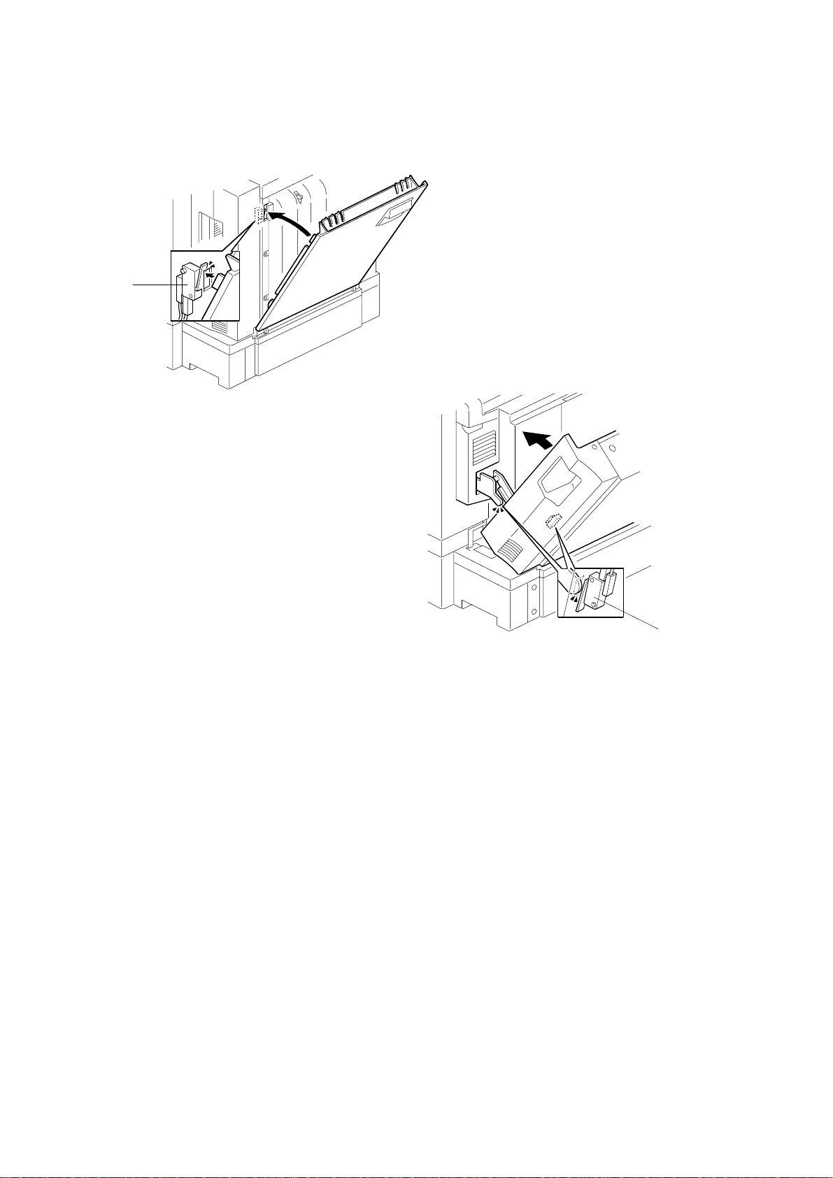
6.3 VERTICAL TRANSPORT UNIT
6.3.1 VERTICAL TRANSPORT UNIT COVER
[A]
[B]
G048R802.WMF
1. Open the vertical unit cover [A].
2. Remove a screw [B] at the joint arm and then remove the cover.
6.3.2 UPPER, LEFT AND RIGHT SIDE COVER
[A]
[C]
[B]
Adjustment
Replacement
G048R803.WMF
1. Open the vertical transport unit (2 screws).
2. Remove the upper cover [A] (3 screws).
3. If present, open the vertical transport unit cover.
4. Remove the left side cover [B] (2 screws) and right side cover [C] (2 screws).
6-5
Page 43

VERTICAL TRANSPORT UNIT 30 June 2000
6.3.3 VERTICAL UNIT SENSORS
[B]
[A]
G048R801.WMF
1. Open the vertical transport unit
2. Remove the brackets [A] (1 screw each).
3. Remove the cables from the connectors, then remove the sensor [B].
6.3.4 VERTICAL TRANSPORT MOTOR
[A]
G048R804.WMF
1. Remove the vertical transport cover. (Refer to section 6.3.1.)
2. Remove the upper and left side cover. (Refer to section 6.3.2.)
3. Remove the motor [A] (2 screws and 1 connector).
6-6
Page 44

30 June 2000 VERTICAL TRANSPORT UNIT
6.3.5 VERTICAL TRANSPORT UNIT
[C]
[B]
[A]
G048R823.WMF
1. Remove the vertical transport cover. (Refer to section 6.3.1.)
2. Remove the upper, left side, right side covers. (Refer to section 6.3.2.)
3. Remove connectors.
4. Remove the brackets on the left [A] and right side [B] (1 screw each).
NOTE: The brackets on the left and right side differ from each other. The left
side bracket has a longer pin than the other.
5. Remove the clip [C] at the joint.
NOTE: Be sure that the harness for the vertical transport motor is removed
beforehand so the harness is not damaged.
Adjustment
Replacement
6-7
Page 45

DUPLEX UNIT 30 June 2000
6.4 DUPLEX UNIT
6.4.1 DUPLEX TRAY
[B]
[A]
G048R828.WMF
1. Pull the tray [A] out about halfway.
2. Loosen the screw that holds the stopper plate [B].
3. Move the stopper plate up and pull out the tray.
6-8
Page 46

30 June 2000 DUPLEX UNIT
6.4.2 REVERSE ROLLER
[C]
[A]
G048R811.WMF
[F]
G048R819.WMF
[G]
[B]
[D]
[E]
G048R813.WMF
Adjustment
Replacement
1. Pull the duplex tray out. (Refer to section 6.4.1.)
2. Remove the left [A] and right side covers [B] (4 screws each).
3. Open the upper and lower guide plate [C].
4. Remove the upper reverse plate [D] (2 clips).
5. Remove the lower reverse plate [E] (2 screws).
NOTE: Be sure not to damage the Myler sheet on the lower plate while
removing the plate.
6. Remove the reverse roller gears [F] and roller [G] (4 clips and 4 bushings).
6-9
Page 47

DUPLEX UNIT 30 June 2000
6.4.3 DUPLEX FEED MOTOR/REVERSE MOTOR
[A]
[B]
G048R815.WMF
1. Remove the duplex tray. (Refer to section 6.4.1.)
2. Remove the left and right side covers. (Refer to section 6.4.2.)
3. Remove the duplex feed motor [A] and duplex reverse motor [B] together with
the brackets (3 screws).
4. Remove motors from brackets (2 screws and 1 connector each).
6.4.4 DUPLEX FEED SENSOR
[A]
[B]
G048R817.WMF
1. Remove the duplex tray. (Refer to section 6.4.1.)
2. Remove the left and right side covers. (Refer to section 6.4.2.)
3. Remove the center plate [A] (2 screws).
4. Remove the duplex feed sensor [B] (1 connector).
NOTE: Be sure not to damage the Myler sheet while removing the plate and
sensor.
6-10
Page 48

30 June 2000 DUPLEX UNIT
6.4.5 JOGER HOME POSITION SENSOR
[B]
[C]
[E]
[A]
[F]
[D]
G048R812.WMF
1. Remove the duplex tray. (Refer to section 6.4.1.)
2. Remove the left and right side covers. (Refer to section 6.4.2.)
3. Remove the center plate and duplex feed sensor connector [A]. (Refer to
section 6.4.4.)
4. Remove the feed [B] and reverse motor [C] connectors.
5. Open the upper and lower guide plates and slide the jogger fences [D] to the
inside.
6. Remove the upper unit [E] (8 screws).
7. Remove the jogger H.P. sensor [F] (1 connector).
Adjustment
Replacement
6-11
Page 49

DUPLEX UNIT 30 June 2000
6.4.6 JOGGER MOTOR/REVERSE SOLENOID
[A]
[B]
G048R814.WMF
[C]
G048R816.WMF
1. Remove the duplex tray. (Refer to section 6.4.1.)
2. Reverse the tray and remove the bottom cover [A] (6 screws).
3. Remove the jogger motor [B] together with bracket (3 screws).
4. Remove the motor from the bracket (2 screws and 1 connector).
5. Remove the reverse solenoid [C] (3 screws, 1 connector and 1 spring).
6-12
Page 50

30 June 2000 DUPLEX UNIT
6.4.7 REVERSE SENSOR
[A]
G048R818.WMF
1. Remove the duplex tray. (Refer to section 6.4.1.)
2. Remove the bottom cover. (Refer to section 6.4.6.)
3. Remove the reverse sensor [A] together with bracket (1 screw).
4. Remove the sensor from the bracket (1 screw and 1 connector).
6.4.8 TEMPERATURE/HUMIDITY SENSOR
[A]
Adjustment
Replacement
G048R808.WMF
1. Open the vertical transport unit.
2. Remove the temperature/humidity sensor [A] (1 screw and 1 connector).
6-13
Page 51

DUPLEX UNIT 30 June 2000
6.4.9 RELAY MOTOR/RELAY ROLLER
[C]
[E]
G048R836.WMF
[F]
[D]
[A]
[B]
G048R835.WMF
[G]
[J]
[H]
G048R834.WMF
[I]
G048R839.WMF
1. Remove the left and right side mainframe covers.
2. Remove the vertical transport unit. (Refer to section 6.3.5.)
3. Remove the connector [A] and the grounding plate [B].
4. Remove the 4 screws [C] that join the mainframe and the duplex unit, then
separate them.
5. Remove the duplex tray. (Refer to section 6.4.1.)
6. Remove the temperature/humidity sensor. (Refer to section 6.4.8.)
7. Reverse the duplex unit and remove the unit frame [D] (8 screws).
8. Remove the gear [E] and motor bracket [F] (1 screw).
9. Remove the relay motor [G] (2 screws).
10. Remove the grounding plate [H] (1 screw).
11. Remove the relay roller drive gear [I] (1 clip)
12. Remove the relay roller [J] (2 clips and 2 bushings).
6-14
Page 52

30 June 2000 FUSING SECTION
6.5 FUSING SECTION
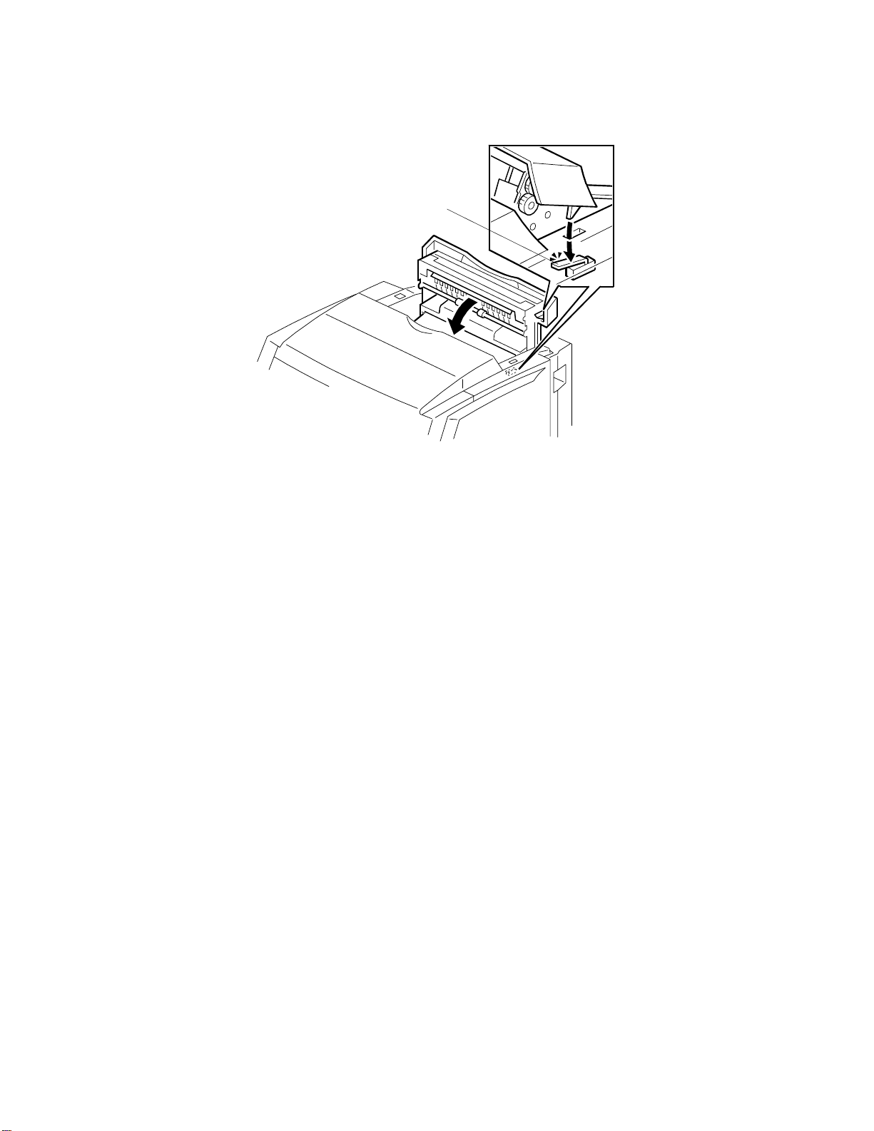
6.5.1 FUSING UNIT
CAUTION
1. The fusing unit is hot. Handle it with care.
2. Be careful not to spill silicone oil.
3. In the event of a fusing-related SC, replace the applicable components
and execute “6: Reset SC” from the engine SP menu to remove the SC.
4. When the fusing unit has been replaced, execute “S3 Maintenance
Clear” from the controller SP menu to reset the fusing counter.
[C]
[A]
[E]
[B]
G048R831.WMF
1. Remove the top cover of mainframe. (Refer to section 6.1.1.)
2. Open the front cover and paper exit unit.
3. Open the oil bottle cover [A] and remove the bottle [B].
4. Remove the harness cover [C] and all connectors.
[D]
G048R832.WMF
Adjustment
Replacement
5. Remove the grounding wire [D] (1 screw).
6. Remove the fusing unit [E] (3 dial screws).
6-15
Page 53

LASER SECTION 30 June 2000
6.6 LASER SECTION
WARNING
Turn off the main switch and unplug the machine before attempting any of
the procedures in this section. Laser beams can seriously damage your
eyes.
6.6.1 CAUTION DECAL LOCATIONS
Two caution decals are located in the laser section as shown below.
LASER_PS2.WMF
G048R504A.WMF
LASER_PS1.WMF
6-16
Page 54

30 June 2000 LASER SECTION
6.6.2 OPTICAL HAUSING UNIT
[A]
G048R827.WMF
[C]
[D]
G048R826.WMF
The procedure for removing the screws on the front side is the same as the base
model (G024). The following section explains how to remove the screws on the
back side.
1. Remove the top cover. (Refer to section 6.1.1.)
2. Remove the paper exit unit. (Refer to section 6.2.3.)
[B]
Adjustment
Replacement
3. Remove the guide plate [A] (4 screws).
4. Remove the clip [B] and the locking bar [C] with releasing the spring.
5. Remove the duct [D] (1 screw).
6. Remove 2 screws fixing the unit at backside.
6-17
Page 55

ELECTRICAL COMPONENTS 30 June 2000
6.7 ELECTRICAL COMPONENTS
6.7.1 CONTROLLER BOARD
NOTE: Before replacing the controller, print the list of settings whenever possible.
In the event of NV-RAM damage, it is necessary to configure all settings
according to this list.
[A]
G048R805.WMF
[C]
[D]
[B]
G048R806.WMF
1. Remove the top, left and right side covers.
2. Remove the vertical transport unit. (Refer to section 6.3.5.)
3. Remove the controller board cover [A] (14 screws).
4. Remove the RPS module [B] and RAM module [C].
5. Remove the controller board [D] (6 screws and 1 connector).
NOTE: 1) If the customer has added optional expansion memory or a NIC, remove
it before replacing the controller. Remember to install the memory or
NIC on the new controller board.
2) To replace the controller boards, remove the NVRAM chip (IC23) on the
old board, install it on the new board, then install the new board. The
NVRAM chip stores user settings and service records. These settings
will be lost if the NVRAM chip is not transferred.
6-18
Page 56

30 June 2000 ELECTRICAL COMPONENTS
6.7.2 DUPLEX DC SUPPLY UNIT
WARNING
To avoid an electric shock, unplug the power cable before replacing the
power supply unit.
[A]
[B]
G048R807.WMF
1. Remove the controller board cover. (Refer to section 6.7.1.)
2. Remove the duplex dc supply unit [A] together with the bracket [B] (2 screws
and 2 connectors).
3. Remove the dc supply unit from the bracket (4 screws).
Adjustment
Replacement
6-19
Page 57

ELECTRICAL COMPONENTS 30 June 2000
6.7.3 POWER SUPPLY UNIT
WARNING
To avoid an electric shock, unplug the power cable before replacing the
power supply unit.
[A]
[B]
G048R820.WMF
1. Remove the controller board. (Refer to section 6.7.1.)
2. Remove the duplex dc supply unit. (Refer to section 6.7.2.)
3. Remove the stay for the paper exit tray [A] (2 screws).
[C]
G048R821.WMF
4. Remove the 6 screws holding the electrical wiring box [B], unplug 4 connectors,
and release 2 hooks. Lift the left side of the electrical wiring box [B] upwards
➀
to swing it out ➁.
5. Remove the power supply unit [C] (6 screws, 6 connectors and 2 hooks).
6-20
Page 58

30 June 2000 ELECTRICAL COMPONENTS
6.7.4 HIGH VOLTAGE SUPPLY UNIT
[A]
[B]
G048R255.WMF
1. Swing the electrical wiring box [A] out. (Refer to section 6.7.3.)
2. Remove the high voltage supply unit [B] (4 screws, 8 connectors and 2 hooks).
WARNING
Carefully connect the high-voltage wires as shown in the diagram below.
Blue connector:
Supply roller
CN190
White connector:
Belt transfer bias roller
White connector:
Development roller
Yellow connector:
Charge corona unit wire
White connector:
Transfer roller
Adjustment
Replacement
Yellow connector:
Development blade
Blue connector:
Charge corona unit grid
G048R512.WMF
6-21
Page 59

ELECTRICAL COMPONENTS 30 June 2000
6.7.5 MCU
[A]
G048R822.WMF
1. Swing the electrical wiring box out. (Refer to section 6.7.3.)
2. Remove the MCU [A] (2 screws and all connectors).
NOTE: When replacing an MCU, remove the NVRAM chip (IC106) from the old
board, install it on the new board, and then install the new board.
In the event of NVRAM damage, install a new NVRAM chip, and contact
your supervisor for additional steps. A forced process control will also be
necessary (Engine SP mode 7: Process Control – Initialize).
6.7.6 DUPLEX DRIVE BOARD
[B]
[A]
G048R833.WMF
1. Remove the duplex backside cover [A] (4 screws).
2. Remove all connectors from the board.
3. Remove the duplex drive board [B] (6 screws, 1 ground wire).
6-22
Page 60

30 June 2000 SC TABLES
7. TROUBLESHOOTING
7.1 SC TABLES
7.1.1 TYPES OF SERVICE CALL
For this printer engine, service calls and process control errors are classified into
three types:
Service Call Type Results
TYPE 1:
Safety warning and immediate
shutdown (Fusing unit errors)
TYPE 2:
Immediate shutdown
TYPE 3:
Log only (Process control errors)
NOTE: In this section, additional or different codes from the base model (G024)
are marked with an asterisk
The printer stops immediately and the LCD displays
an SC error message. The error is logged.
The printer stops immediately and the LCD displays
an SC error message. The error is logged.
The printer does not stop. No SC error message is
displayed. The error is only logged.
.
“*”
Fusing Unit SC Errors
Fusing unit SC errors (Type 1 errors) can be released by executing the Reset SC
item in the engine SP mode menu. They cannot be released by turning the main
power switch off and on.
Trouble-
shooting
7-1
Page 61

SC TABLES 30 June 2000
7.1.2 SC ERROR LIST
NOTE: The errors marked with an asterisk “*” are additional or changed codes for
this model.
SC
No.
20
21
22
23
24
25
26
* 27
Type Name Occurre nce conditi ons Detection conditions Cause
Type 2 Optional tray
Type 1 Pressure
Type 1 High
Type 1 Low
Type 1 Hot roller
Type 1 High hot
Type 1
Type 2
unit error
roller
thermistor
error
pressure
roller
temperature
pressure
roller
temperature
thermistor
error
roller
temperature
Low hot
roller
temperature
Zero-cross
cycle
detection
error
The detection signal for
the 500-sheet paper tray
unit is abnormal.
The roller temperature
has been at 0°C for five
seconds.
The roller temperature
has been at 190°C or
higher for three seconds.
Reheating has been done
and the motor is not
running, or 60 seconds
have passed after the
main motor halted. Then,
the roller temperature has
been below 130°C for 60
seconds
The roller temperature
has been 0°C for five
seconds.
The roller temperature
has been 190°C or higher
for three seconds.
Reheat has been done
and the motor is not
running, or 60 seconds
have passed after main
motor halt. Then, the
roller temperature has
been below 130°C for 60
seconds
50 Hz AC
The number of zero-cross
is detected less than 89
times or more than 111
times in one second for
continuous 5 seconds.
60 Hz AC
The number of zero-cross
is detected less than 109
times or more than 131
times in one second for
continuous 5 seconds.
Always monitored The optional tray
unit connector has a
bad connection.
No detection in the
event of a jam/door
open, SC, unit
absence, energysaving mode, or lack
of fusing unit
No detection in the
event of SC or lack of
fusing unit
No detection in the
event of a jam/door
open, SC, unit
absence, energysaving mode, or lack
of fusing unit
No detection in the
event of a jam/door
open, SC, unit
absence, energysaving mode, or lack
of fusing unit
No detection in the
event of SC or fusing
unit absence
No detection in the
event of a jam/door
open, SC, unit
absence, energysaving mode, or
fusing unit absence
No detection in the
event of a jam/door
open, SC, unit
absence, energysaving mode, or
fusing unit absence
Pressure roller
thermistor, MCU
Pressure roller
thermistor, MCU
Pressure roller
thermistor, MCU,
pressure roller lamp
connector
Hot roller thermistor,
MCU
Hot roller thermistor,
MCU
Hot roller thermistor,
MCU, hot roller
lamp connector
Frequency of the
commercial AC
power
7-2
Page 62

30 June 2000 SC TABLES
SC
No.
28
29
31
32
33
34
35
36
Type Name Occurre nce conditi ons Detection conditions Cause
Type 2
Type 2 Primary
Type 2 Supply bias
Type 2
Type 2 Charge
Type 2 Charge
Type 2 Main motor
Type 2 PCU motor
Paper
transfer
positive bias
release error
transfer bias
open
error
Blade bias
error
corona unit
bias open
corona unit
grid bias
error
error
error
The PWM duty has been
50% or higher for 240
ms. Or, the paper transfer
roller clutch does not
operate.
The PWM duty has been
50% or higher for 240
ms.
The voltage has been
higher than the
appropriate control
voltage for the target
voltage for 240 ms.
However, detection is
disabled when the
calculated control voltage
is 5 V or higher.
The voltage has been
higher than the
appropriate control
voltage for the target
voltage for 240 ms.
However, detection is
disabled when the
calculated control voltage
is 5 V or higher.
The PWM duty has been
50% or higher for 240
ms.
The voltage has been
higher than the
appropriate control
voltage for the target
voltage for 240 ms.
However, detection is
disabled when the
calculated control voltage
is 5 V or higher.
Continuous unlock for
two seconds
Continuous unlock for
two seconds
Detection starts 60
ms after control starts
for this component.
Detection starts 60
ms after control starts
for this component.
Detection starts 60
ms after control starts
for this component.
Detection starts 60
ms after control starts
for this component.
Detection starts 60
ms after control starts
for this component.
Detection starts 60
ms after control starts
for this component.
There is a
disconnection in the
paper transfer bias
supply circuit.
(Deformation of
terminals or springs,
dirty bearings)
When the
contact/separation
lever is normal: Bad
transfer roller
position sensor,
harness, or MCU
When the
contact/separation
lever is faulty: Bad
transfer roller clutch
or MCU
There is a
disconnection in the
primary transfer bias
supply circuit. (Dirty
or deformed
electrodes)
There is a short
circuit in the supply
bias supply circuit
(due to deformed
terminals or
electrodes or
conductive foreign
matter)
There is a short
circuit in the blade
bias supply circuit.
There is
disconnection in the
charge corona unit
bias supply circuit.
(Dirty or deformed
electrodes)
There is a short
circuit in the charge
corona unit grid bias
supply circuit (due
to deformed
terminals or
electrodes or
conductive foreign
matters).
Main motor, MCU
PCU motor, MCU
Trouble-
shooting
7-3
Page 63

SC TABLES 30 June 2000
SC
No.
38
39
40
41
42
43
45
46
47
48
49
Type Name Occurre nce conditi ons Detection conditions Cause
Type 2
Type 2
Type 2
Type 2 Transfer belt
Type 2
Type 2
Type 2 Charge bias
Type 2 Paper
Type 2
Type 2
Type 1 Pressure
Revolver
motor error
Polygon
mirror motor
error
ID sensor
error
H.P. sensor
error
Laser diode
error
Synchronizat
ion detection
error
short
transfer
positive
current error
Paper
transfer
negative bias
open
Paper
transfer
negative
current error
roller reheat
timeout
Movement to the home
position took four or more
seconds. For black,
movement to the home
position took one second
or longer.
Continuous unlock for
two seconds
The ID sensor output
voltage is not between
0.1 V and 1.1 V while the
ID sensor LED is off.
No mark has been
detected for 500 ms
during PCU motor
operation.
LD error (abnormal laser
power output)
Synchronization detection
error of the optical unit
A/D converted voltage
has been 4.8 V or more
for 240 ms.
A/D converted voltage
has been 0.2 V or less for
240 ms.
The PWM duty has been
50% or greater for 240
ms.
A/D converted voltage
has been 4.8 V or more
for 240 ms.
When reheating, the
roller temperature does
not reach the reheat start
temperature (target
temperature –20°C)
within five minutes.
Revolver motor,
MCU, or incorrect
installation of color
development unit
Polygon mirror
motor, MCU
ID sensor calibration ID sensor
Transfer belt H.P.
sensor, MCU
LD, LD control
board
During polygon mirror
motor revolution
Detection starts 60
ms after control starts
for this component.
Detection starts 60
ms after control starts
for this component.
Detection starts 60
ms after control starts
for this component.
Detection starts 60
ms after control starts
for this component.
During re-heating Pressure roller
Synchronization
detection board, LD
control board
There is a short
circuit in the charge
bias supply circuit
(due to deformed
terminals or
electrodes or
conductive foreign
matter)
There is a short
circuit in the paper
transfer bias supply
circuit (due to
deformed terminals
or electrodes or
conductive foreign
matter)
There is
disconnection in the
paper transfer bias
supply circuit. (Dirty
or deformed
electrodes)
There is a short
circuit in the paper
transfer bias supply
circuit (due to
deformed terminals
or electrodes or
conductive foreign
matter)
thermistor, pressure
roller lamp
connector, MCU
7-4
Page 64

30 June 2000 SC TABLES
SC
No.
50
51
52
57
59
60
*61
*62
*63
Type Name Occurre nce conditi ons Detection conditions Cause
Type 1
Type 1 Pressure
Type 1 Hot roller
Type 2 Print
Type 2
Type 2 Humidity
Type 2 Paper
Type 2 Auto-Duplex
Type 2 Jogger
Hot roller
reheat
timeout
roller lamp
full-power
operation
error
lamp fullpower
operation
error
command
error
Temperature
sensor error
sensor error
Transfer
roller error
unit detection
error.
movement
error
When reheating, the
roller temperature does
not reach the reheat start
temperature (target
temperature –10°C)
within five minutes.
When full-power
operation occurs during
reheating, the main motor
is not running and the
difference between the
current temperature and
that of 60 seconds ago is
18°C or less.
When full-power
operation occurs during
reheating, the main motor
is not running and the
difference between the
current temperature and
that of 60 seconds ago is
18°C or less.
When an abnormal
combination of print
commands is received.
5 V (4.75 V) or more has
continuously been
detected for five seconds.
5 V (4.75 V) or more has
continuously been
detected for five seconds.
Paper transfer position
sensor does not detect
the movement of roller.
Auto-duplex unit is
detected on the manualduplex model.
Jogger home position
sensor does not turn on.
During reheating
No detection in the
event of a jam/door
open, SC, unit
absence, energysaving mode, or
fusing unit absence.
No detection in the
event of a jam/door
open, SC, unit
absence, energysaving mode, or
fusing unit absence.
When the power is
on, or the AC
development bias is
off.
When the power is
on, or the AC
development bias is
off.
When the contact and
separation of the
roller need to be
detected.
When the power is on MCU
During duplex printing Jogger motor
Hot roller thermistor,
hot roller lamp
connector, MCU
Pressure roller
thermistor, pressure
roller lamp
connector, MCU
Hot roller thermistor,
hot roller lamp
connector, MCU
Temperature sensor
Humidity sensor
Transfer roller
position sensor
MCU
Harness
Transfer roller clutch
Jogger HP sensor
MCU
DDB
7-5
Trouble-
shooting
Page 65

SC TABLES 30 June 2000
7.1.3 PROCESS CONTRL ERROR LIST
PE
No.
103 Type 3
104 Type 3
105 Type 3
110 Type 3
111 Type 3
112 Type 3
116 Type 3
Type Name Occurre nce conditi ons Detection conditions Cause
K ID sensor
error
ID sensor
output error
(rough
adjustment)
ID sensor
output error
(fine
adjustment)
ID sensor
pattern error
(Cyan)
ID sensor
pattern error
(Magenta)
ID sensor
pattern error
(Yellow)
ID sensor
pattern error
(K)
While the LED is off, the
ID sensor output does not
meet the standard
voltage (between 0.05 V
and 1.5 V).
The difference in ID
sensor outputs when the
transfer belt is read and
when the LED is off does
not meet the standard
voltage (Vbkcal ± 0.4 V).
The difference in ID
sensor outputs when the
transfer belt is read and
when the LED is off does
not meet the standard
voltage (Vbkcal ± 0.1 V).
The slope γM of the line
representing the
relationship between the
C development bias and
attached toner amount is
not between –0.01 and –
0.0005.
The slope γM of the line
representing the
relationship between the
M development bias and
attached toner amount is
not between –0.01 and –
0.0005.
The slope γM of the line
representing the
relationship between the
Y development bias and
attached toner amount is
not between –0.01 and –
0.0005.
The slope γM of the line
representing the
relationship between the
K development bias and
attached toner amount is
not between –0.01 and –
0.001.
ID sensor (K)
calibration
ID sensor (K)
calibration
ID sensor (K)
calibration
Color DTM
initialization
Color DTM
initialization
Color DTM
initialization
Color DTM
initialization
When the output
meets the standard
voltage: MCU,
harness
When the output
does not meet the
standard:
sensor
K ID sensor, MCU,
transfer belt error,
transfer belt surface
unevenness,
incorrect ID sensor
installation
K ID sensor, MCU,
transfer belt error,
transfer belt surface
unevenness
Incorrect color DTM
installation, incorrect
PCU installation,
development bias
error, MCU, LD
control malfunction,
loss of
synchronization
Incorrect color DTM
installation, incorrect
PCU installation,
development bias
error, MCU, LD
control malfunction,
loss of
synchronization
Incorrect color DTM
installation, incorrect
PCU installation,
development bias
error, MCU, LD
control malfunction,
loss of
synchronization
Incorrect K DTM
installation, incorrect
PCU installation,
development bias
error, MCU, LD
control malfunction,
loss of
synchronization
K ID
7-6
Page 66

30 June 2000 SC TABLES
PE
No.
118 Type 3
123 Type 3
Type Name Occurre nce conditi ons Detection conditions Cause
ID sensor
pattern read
error (K)
ID sensor
pattern error
(K)
The difference in ID
sensor outputs when the
ID sensor pattern is read
and when the
background surface of
the transfer belt is read is
0.8 V or less.
The slope γM of the line
representing the
relationship between the
DTM bias and attached
toner amount is not
between –0.01 and –
0.001.
K-DTM bias
initialization
K-DTM bias control Incorrect DTM
Incorrect DTM
installation, incorrect
PCU installation,
development bias
error, MCU, LD
control malfunction,
loss of
synchronization
installation, incorrect
PCU installation,
development bias
error, MCU, LD
control malfunction,
loss of
synchronization
7-7
Trouble-
shooting
Page 67

USER ERROR LIST 30 June 2000
7.2 USER ERROR LIST
This table only shows additional and different items from the base model (G024).
Error
Add Toner: xx Printing stops. The PCU counter is
Low on : x,x,x Printing can be
Change PCU Printing can be
Change
Fusing Unit
Need Charger Printing can be
Vertical
Transport Unit
Cover Open
Operation
after error
done.
done.
Printing can be
done.
done.
Printing is disabled. Always monitored Close the cover.
Detection
conditions
increased to 100
after toner near-end
is detected.
Toner near-end
detection is enabled
two seconds after
the development
drive solenoid turns
on until it turns off.
The toner near-end
message is
displayed when
toner end is detected
five times.
The CPU counter
reaches 72,000.
The fusing unit
counter reaches
60,000.
Charger counter
reaches 24 K.
Release method Remarks
Replace the
DTM.
Replace the
DTM.
Replace the PCU
to reset the
counter.
Manually release
the message
using
‘Maintenance
Clear’ in
controller SP
mode.
Replace charger
unit and reset the
charger counter.
This error is shown
when “Stop” is
selected in the Toner
Empty menu.
When near-end is
detected, closing the
front cover initiates
recovery. If the toner
near-end status is
cleared, it is not
detected during
recovery. In singlecolor (black-and-white)
continuous output,
toner near-end is
detected during
process control.
Counting (upon exit)
A3/DLT or smaller
K single-color: Plus 1
Full color: Plus 4
For sizes larger than
A3/DLT, counting
doubles.
This is not shown if
meter-click mode is
selected.
A3 or larger:
Number of sheets that
have passed x 2
Smaller than A3:
Number of sheets that
have passed
This is not shown if
meter-click mode is
selected.
This is not shown if
meter-click mode is
selected.
7-8
Page 68

30 June 2000 USER ERROR LIST
Error
Duplex-tray
Jam
Vertical
Transport Unit
Jam
Duplex Unit
Exit Jam
Operation
after error
Printing is disabled.
Printing is disabled. The vertical
Printing is disabled.
Detection
conditions
<Case 1>
The duplex feed
sensor does not
detect paper 3.2
seconds after the
vertical transport exit
sensor detects
paper.
<Case 2>
The reverse sensor
does not detect
paper 3.2 seconds
after the duplex feed
sensor detects
paper.
<Case 3>
The reverse sensor
does not detect
paper 0.5 seconds
after the duplex
reverse motor turns
on.
transport entrance
sensor does not
detect paper 3.2
seconds after the
paper exit sensor in
fusing unit detects
paper.
Or
The vertical
transport exit sensor
does not detect
paper 2.8 seconds
after the vertical
entrance sensor
detects paper.
The pull-out sensor
for the main frame
does not detect
paper 0.9 seconds
after the relay motor
turns on.
Release method Remarks
Remove the
jammed paper.
Remove the
jammed paper by
opening the
vertical transport
unit.
7-9
Trouble-
shooting
Page 69

12345678
A
B
C
D
Paper Feed Clutch
E
Registration Clutch
Development Drive
Transfer Roller Clutch
F
Used Toner Sensor
PCU Reset Sensor
G
H
I
Registration Sensor
J
Power Cord
LINE
NUTRAL
Door Safety Switch
Exit Cover Switch
By-pass Feed Clutch
Relay Roller Clutch
Transfer Belt Cleaning Solenoid
Solenoid
Pull-out Sensor
ID Sensor
Temperature Humidity Sensor
By-pass Paper
End Sensor
Transfer Roller Position Sensor
Revolver H.P.
SOL3
Charge Corona Set Switch
Paper End Sensor
Paper Size Switch
S10
Toner End Sensor
S13
Sensor
Transfer Belt H.P. Sensor
S15
( )
CN802-1
CN805-1
DTM Cover Switch
CL2
CL4
Pull-out Clutch
CL6
PCU Set Switch
3
2
S2
1
CN813
3
2
S4
1
CN827
3
2
S6
1
CN823
5
4
3
S8
2
CN820
1
3
2
1
CN817
3
2
1
CN874
3
2
1
CN831
Oil End Sensor
AC
DC
,P
Pulse
Signal Direction
Active High
Active Low
Voltage
T108
Inlet
T109
Ground
CN801-2
CN802-2
CN803-2
CN805-2
CN804-1
High Voltage
C
Supply Board
G
TB
TP
PCB3
BL
BSPDevelopment
CL1
CL3
SOL2
CL5
S1
S3
S5
S7
S9
S11
S12
S14
S17
T101
T102
122
122
122
122
CN815
CN822
3
2
1
CN818
4
3
2
1
CN824
6
5
4
3
CN814CN826
1
3
2
1
3
2
1
CN821
3
2
1
CN830
3
2
1
CN828
CN801-1
CN803-1
CN804-2
A10
A9
A8
A7
A6
A5
A4
A3
A2
A1
B10
B9
CN190
B8
B7
B6
B5
B4
B3
B2
B1
122
1
122
1
122
1
CN841 CN839 CN837
122
1
CN844
1
2
3
4
5
6
7
1
2
3
4
5
6
1
2
3
4
5
FU1
250V
15A
CN105-6
CN105-3
T115
T113
1
1
1
CN840 CN838 CN836
1
CN843
7
6
5
4
3
CN870
2
1
6
5
4
3
CN872
2
1
5
4
3
2
CN871
1
Main Switch
T116
T112
CN105-1
CN105-4
1
2
A1
A2
A3
A4
A5
A6
A7
A8
A9
A10
B1
B2
B3
B4
B5
B6
B7
B8
B9
B10
A1
A2
A4
A5
A7
A8
A10
A11
B1
B2
B4
B5
B7
B8
B10
B11
1
2
3
4
5
6
7
9
10
11
A2
A3
A4
A5
A6
A7
A9
A10
A11
A12
B1
B2
B3
B4
B5
B7
B8
B9
B10
B12
1
2
3
4
5
6
8
9
10
11
12
13
A1
A2
A3
A4
A5
A6
A7
A8
B1
Power Supply Unit
PCB1
DC Voltage
Generator
5V
5V INT
24V
24V INTR
CN204
24V INR
24V INTS
24V DB
24V DBSW
CN250
GND (COM3)
24V INT
5V
GND (COM4)
FB VBL (
W
5
W
FB VSP (
5 → 0 to 5)
W
FB ITP (
5 → 0 to 5)
W
5 → 0 to 5)
FB VTB (
W
FB VG (
5 → 0 to 5)
FB IC (
W
5 → 0 to 5)
V
PWM C (
CN205
CN212
CN207
CN209
CN209 CN208
CN210
123456789
TXD
V
PWM G (
PWM TB (
PWM TP+ (
PWM SP (
PWM BL (
PWM TP– (
W
TRG G (
TRG AC (
W
TRG B (
24V
XBPFEDCL (
24V
XPAPEOCL (
24V
XTRNROCL (
24V
XREGICL (
24V
XTRCBESL (
24V
XDEVSLC (
24V
XPIUPCL (
24V
XTRCROCL (
GND (COM2)
XTNBTS (
GND (COM2)
XTNFULS (
5V
GND (COM2)
XINPUT (
W
GND (COM2)
XPCUNOS (
5V
GND (COM2)
XPAPEND (
5V
GND (COM2)
XPICKS (
W
5V
V
XNOB0 (
V
XNOB1 (
GND (COM2)
V
XNOB2 (
W
LEDIN (
W5 →
VOUT1 (
W
VOUT2 (
GND (COM2)
5V
XTHREMO (
GND (COM4)
GND (COM4)
XHUMIDS (
N.C.
5V
GND (COM2)
XBPFEDS (
5V
GND (COM2)
XTRCRLS (
5V
GND (COM2)
XCOLEND (
5V
GND (COM2)
XDTMS (
W
5V
GND (COM2)
MARKSEN (
5V
GND (COM2)
XREGIST (
5V
GND (COM2)
XOILEND (
5V
5V5V5V
XOFGATE
GND (COM2)
GND (COM2)
5 → 0/5)
5 → 0/5)
V
V
V5 →
V
5 → 0/5)
V
5)
W
5)
5)
W
W
W
W
5)
W
5)
W
W
5)
5)
5)
5)
5 → 0 to 4)
5 → 0 to 5)
W
W
W
W
W
5)
W
W
W
T105
T106
T107
T108
TF1
2
CN832CN834
L3
2
FM2
2
CN875
FM3
2
CN878
CN849
CN846CN850
CN851
CN855
CN863
P1SPS0
P2
P3
P4
P5
P6
P7
P8
P9
P10
P11
D(6)
OPR_W
GND (COM2)
GND (COM2)
GND (COM2)
L1
L2
Pressure Roller Lamp
Fusing Unit
Quenching Lamp
Laser Diode (LD) Unit
Operation Panel
CN863
CN860-2
CN852
P22
P21
P20
P19
P18
P17
P16
P15
P14
P13
P12
D(4)
LED4ON
LED3ON
GND (COM2)
3
2
1
CN809
DTM Set Sensor
211
5
4
3
2
1
CN85222CN860
CN860
CN852
860-2
P11
J11
P10
J10
P9
J9
P8
J8
P7
J7
P6
J6
P5
J5
P4
J4
P3
J3
P2
J2
P1
J1
XVDATA2
XVDATA0
GND (COM2)
GND (COM2)
GND (COM2)
TF1
Hot Roller
Thermofuse
TF2
Pressure Roller
Thermofuse
S19
Exit Sensor
211
211
2
CN877
211
211
2
CN835
211
2
CN876
211
2
CN833
211
10
9
8
7
6
5
4
3
2
1
1
5
2
4
3
3
4
2
CN847
5
1
7
6
5
4
3
2
1
26
24
(Option)
Paper Fedd Unit
SPS1
SPS2
SPEND
SPSEN
XSPST0
XSPST1
SPSEL
XSNDFD0
XSNDCL0
XSNDCK0
5V5V5V
ENABLE
GND (COM2)
CN102-1
Power Relay
Heater Control
Circuit
Vcc (5.1V)
Vcc (5.1V)
CN101-1
CN101-2
CN101-3
1234567
→→→→
0 to 5)
5 → 0/5)
5 → 0/5)
0/5)
5 → 0/5)
W
24)
W
24)
W
24)
24 → 0/24)
W
24 → 0/24)
24 → 0/24)
24 → 0/24)
W
24)
5)
5)
5)
0 to 5)
5 → 0 to 5)
5 → 0 to 5)
5)
5)
5)
5)
5)
5)
1011121314151617181920212223242526272829303132333435363738394041424344454647484950515253545556575859606162636465666768697071727374757677787980
5V
XILSYNC
GND (COM2)
GND (COM1) (Vcc)
GND (COM1) (Vcc)
Vaa (24V)
Vaa (24V)
CN101-4
CN101-5
CN101-6
CN101-7
CN201
ICLOCK
XVDATA7
GND (COM2)
GND (COM2)
GND (COM3) (Vaa)
GND (COM3) (Vaa)
CN101-8
12345
8
CN202 CN203
XFIXRAI (W24)
XFIXRA2 (W24)
XPWRRL (W24)
CN217
1
3
5
7
9
11
13
15
17
19
21
23
CN221
1
3
5
7
9
11
13
15
17
19
21
23 1
CN218
A1
A2
A3
A4
A5
A6
A7
A8
A9
A10
A11
N.C.
XVDATA5
XVDATA3
XVDATA1
GND (COM2)
GND (COM2)
GND (COM2)
GND (COM2)
123456789
6
24 V INT
GND (COM2)
GND (COM4)
ZCROSS (W5 → 0/5)
Main Control Board
5VINT
GND (COM2)
5VINT
GND (COM2)
GND (COM2)
LDOFF
XLDERR
LDCLK
GND (COM2)
GND (COM2)
SPEND
SPSEN
XSPST0
XSPST1
SPSEL
SNDFD0
SNDCL0
SNDCK0
XS
GND (COM2)
PCB2
XLD7
XLD5
XLD3
XLD1
LED2
LED4
SW2
SW4
SW6
SW8
5V
E
DB4
DB6
SPS0
SPS1
SPS2
N.C.
RSEL
GND (COM2)
XFTFRM2 (W5 → 0 to 5)
(V5)
W
5)
(
W
(
5)
W
5)
(
(
W
5)
W
5)
(
(
W
W
(
5)
5)
W
5)
(
W
(
5)
W
5)
(
(
W
5)
W
(
5)
(
W
5)
V
(
5)
V
(
5)
V
(
5)
(W5)
W
(
5)
W
5)
(
W
(
5)
W
(
5)
W
5)
(
W
5)
(
V
5)
(
V
5)
(
V
(
5)
V
(
5)
D(7)
GND (COM2)
GND (COM2)
GND (COM4)
GND (COM2)
XFTHRM1 (W5 → 0 to 5)
CN851
25
23
21
19
17
15
13
P
11
P
9
P
7
P
5
P
3
125
CN855
23
21
19
17
15
13
11
9
7
5
3
CN852
P11
P10
P9
P8
P7
P6
P5
P4
P3
P2
P
P1
D(5)
LED1ON
GND (COM2)
CN102-2
CN102-3
CN102-4
10
5V
REVMOBB (
REVMOAB (
5VINT
GND (COM2)
5VINT
GND (COM2)
LDMODE
LEVEL
XLDON
GND (COM2)
GND (COM2)
OPRXW
GND (COM2)
SDDFD1
SNDCL1
SNDK1
GND (COM3)
GND (COM3)
GND (COM3)
CN223
CN1
SW4ON
SW7ON
SW8ON
PCB8
XBPFEDSL (
XRRMLED (
XFMSTAT2 (
XFMSTAT1 (
XFMSTAT3 (
XFMSTAT4 (
XFMSTAT5 (
REVMOB (
REVMOA (
XBMLOCK (
BMOCLK(
BMSPEED (
XBMSTART (
XPMSTART (
PMCLK (
XMMLOCK (
MMSTART (
MMSPEED (
LDS
XLD6
XLD4
XLD2
XLD0
LED1
LED3
SW1
SW3
SW5
SW7
5V
RS
DB5
DB7
5V
24V
24V
24V
RXD
XOLSYNC
GND (COM2)
GND (COM2)
5V
XFSET (W5)
GND (COM1)
XPAPOUT (W5)
CN217 CN851
2
4
6
8
10
12
14
16
18
20
22
24
26
CN221 CN855
2
4
6
8
10
12
14
16
18 8
20 6
22 4
24 2
CN218 CN852
B1
B2
B3
B4
B5
B6
B7
B8
B9 P14
B10 P13
B11 P12
5V
5V
SW3ON
LED2ON
Controller Board WIN
W
24 → 0/24)
W
24 → 0/24)
W
24 → 0/24)
W
24 → 0/24)
GND (COM3)
GND (COM2)
W
24 → 0/24)
BMFF (
BMFR (
XDPINI (
GND (COM2)
GND (COM3)
XSCRDY (
W
24 → 0/24)
GND (COM3)
GND (COM3)
W
5)
(
(V5)
W
(
5)
V
5)
(
W
5)
(
W
(
5)
W
(
5)
W
(
5)
W
5)
(
W
(
5)
W
5)
(
(
W
5)
W
(
5)
(
W
5)
W
5)
(
V
(
5)
V
(
5)
V
(
5)
V
5)
(
V
(
5)
(
V
5)
OCLOCK
GND (COM2)
CN1
CN2-2
CN3
CN4-2
211
3
2
1
3
2
1
24V
W
24)
24V
W
24)
24V
W
24)
24V
W
24)
24V
W
24)
24V
W
24)
24V
W
24)
24V INT
24V INT
24V INT
5V
W
24)
W
24)
W
24)
W
24)
W
24)
W
5)
5V
24V
W
24)
W
24)
24V INT
24V INT
W
24)
W
24)
W
24)
26
24
22
20
18
16
14
12
P
10
P
8
P
6
P
4
2
24
22
20
18
16
14
12
10
P22
P21
P20
P19
P
P18
P17
P16
P15
5V5V5V
XIFGATE
GND (COM2)
2
CN807
2
1
1
2
3
CN811 CN888
CN808
S16
CN211CN214CN213
CN215CN216
CN217
CN221
CN218
5V
XVDATA6
1
2
1
2
3
4
5
6
7
8
9
10
11
12
13
14
1
2
3
4
5
6
1
2
3
4
5
6
7
8
9
10
1
2
3
4
5
6
7
8
1
2
3
4
5
6
7
XVDATA4
GND (COM2)
Hot Roller Lamp
Pressure Roller
Thermisotr
TF2
SOL1
FM1
Exhaust Fan
FM5
Transport Fan
FM4
M1
M2
3
2
PCB4
1
CN845
M3
M4
PCB5
PCB7
(Option)
Paper Feed Unit
CN860
860-2
J11
J10
GND (COM2)
J9
XSNDFD1
J8
XSNDCL1
J7
XSNDCK1
J6
24V
J5
24V
J4
24V
J3
GND (COM3)
J2
GND (COM3)
J1
GND (COM3)
NC
NC
SW1ON
SW2ON
SW5ON
SW6ON
Hot Roller
Thermistor
By-pass Feed
Solenoid
Transport Fan
Charge Inlet Fan
Inlet Fan
Revolver Motor
PCU Motor
Laser Synchronization
Detector Board
Polygon Mirror Motor
Main Motor
CN863
5V
P22
P21
P20
P19
P18
P17
P16
P15
P14
P13
P12
A
B
C
D
E
F
G
CN863-2
H
I
J
Option Board
K
Point to Point Diagram (G047/G048)
12345678
(Option)
Network Interface Board
(Option)
IEEE 1284 Parallel
Interface
(Option)
16 MB/32 MB Memory
(Option)
16 MB/32 MB Memory
(Option)
Ricoh-script 2
K
Page 70

ELECTRICAL COMPONENT LAYOUT
SENSORS
14
1
2
13
12
11
10
9
8
7
Index No. Description Symbol P-to-P
1 Exit Sensor S19 B7
2 Oil End Sensor S17 J1
3 Transfer Belt H.P. Sensor S14 I2
4 Transfer Roller Position Sensor S11 H2
5 Used Toner Sensor S2 F1
6 PCU Reset Sensor S4 F1
7 Paper End Sensor S5 G2
8 ID Sensor S8 G1
9 Pull-out Sensor S6 G1
10 By-pass Paper End Sensor S10 H1
11 Registration Sensor S15 I1
12 Toner End Sensor S12 I2
13 Revolver H.P. Sensor S13 I1
14 DTM Set Sensor S16 B6
G048V551A.WMF
1
SWITCHES
7
6
3
4
5
5
6
4
G048V551.WMF
Index No. Description Symbol P-to-P
1 Main Switch SW1 B3
2Exit Cover Switch SW2 C2
3 Door Safety Switches SW3 B2
4 Paper Size Switch S7 G2
5 PCU Set Switch S1 F2
6 Charge Corona Unit Set Switch S3 F2
7DTM Cover Switch SW4 C2
2
3
PCBS AND PSU
1
9
2
MOTORS, CLUTCHES, AND SOLENOIDS
17
16
15
14
13
12
11
10
9
Index No. Description Symbol P-to-P
1 Exhaust Fan FM2 C8
2 PCU Motor M2 D8
3 Transfer Belt Cleaning Solenoid SOL2 E2
4 Main Motor M4 F8
5 Revolver Motor M1 D8
6 Polygon Mirror Motor M3 E8
7 Development Drive Solenoid SOL3 E1
8 Pull-out Clutch CL5 F2
9 Paper Feed Clutch CL2 E1
10 Relay Roller Clutch CL3 E2
11 By-pass Feed Clutch CL1 E2
12 Registration Clutch CL4 E1
13 Transfer Roller Clutch CL6 F1
14 By-pass Feed Solenoid SOL1 B8
15 Charge Inlet Fan FM5 C8
16 Inlet Fan FM4 C8
17 Transport Fans FM1, FM3 C7
8
G048V552.WMF
8
3
4
5
7
1
6
2
3
4
5
6
7
Index No. Description Symbol P-to-P
1 Power Supply Unit (PSU) PCB1 A3-A5
2 Controller Board PCB8 J3-J7
3 High Voltage Supply Board PCB3 D2
4 Temperature/Humidity Sensor S9 H2
5 Main Control Unit (MCU) PCB2 C3-I6
6 Laser Synchronization Detector Board PCB4 E8
7 Quenching Lamp L3 C7
8 Laser Diode (LD) Unit PCB5 F7
9 Operation Panel PCB7 G7
G048V111.WMF
THERMISTORS, HEATERS, AND FUSES
1
2
6
5
4
3
G048V111.WMF
Index No. Description Symbol P-to-P
1 Pressure Roller Thermistor TH1 B7
2 Pressure Roller Lamp L2 A7
3 Hot Roller Thermofuse TF1 A7
4 Hot Roller Thermistor TH2 B8
5 Hot Roller Lamp L1 A7
6 Pressure Roller Thermofuse TF2 A7
Page 71

12345678
A
B
C
D
E
F
G
H
I
J
MCU
PCB2
DIV_SL (
REVMOA (
FEDMTCLK (
XFEDMTON (
PLMTCLK (
XPLMTON (
PLTFMTCLK (
XTFMTON (
TRVMTCLK (
XTRVMTON (
TRVMTINV (
JGMTCLK (
JGMTON (
JGMTINV (
XTRVSOL (
XTRVPAP1 (
XTRVPAP2 (
XTRVJGHP (
XUNITSET (
XPULLSET (
XTRVPAPR (
SNDCD0 (
SNDCL0 (
SNDCK0 (
SNDCD1 (
SNDCL1 (
SNDCK1 (
24V DBSW
W
GND (COM2)
PAPS_L (
GND (COM2)
PAPS_V (
W
24 → 0/24)
W
5 → 0/5)
W
5 → 0/5)
W
5 → 0/5)
W
5 → 0/5)
W
5 → 0/5)
+24V DBSW
+24V DBSW
GND (COM3)
GND (COM3)
GND (COM2)
SPS0 (W5)
SPS1 (
SPS2 (
SPEND (
SPSEN (
XPST0 (
XPST1 (
SPSEL (
GND (COM1)
GND (COM3)
GND (COM3)
GND (COM3)
24V DB
24V
24)
W
5)
5V
W
5)
5V
W
5)
W
5)
W
5)
W
5)
W
5)
W
5)
W
5)
W
5)
5V
W
5)
W
5)
W
5)
W
5)
W
5)
W
5)
W
5)
W
5)
W
5)
W
5)
W
5)
W
5)
V
5)
V
5)
V
5)
V
5)
5V
V
5)
V
5)
V
5)
24V
24V
24V
1
2
3
4
CN255
1
1
2
CN250CN251
12211
4
1
235
6
34
4
CN252
5
621
12
1
11
2
10
3
9
4
8
5
7
6
6
7
5
8
CN253
4
9
3
10
2
11
1
12
13
1
2
12
3
11
4
10
5
9
6
8
7
7
6
8
CN254
5
9
4
10
3
11
2
12
1
13
11
A1
10
A2
9
A3
8
A4
7
A5
6
A6
5
A7
4
A8
3
A9
2
A10
1
A11
11
B1
CN218
10
B2
9
B3
8
B4
7
B5
6
B6
5
B7
4
B8
3
B9
2
B10
1
B11
Vertical Transport Cover Switch
122
CN812CN810
2
2
3
CN816
5
6
1
2
3
4
5
6
7
8
CN854CN886CN887 CN856
9
10
11
12
Relay Motor
1
2
3
4
5
6
7
8
9
10
11
1
2
3
4
5
6
7
8
9
10
11
CN806-1
31
2
1
M6
P11
P10
P9
P8
P7
P6
P5
P4
P3
P2
P1
P22
P21
P20
P19
P18
P17
P16
P15
P14
P13
P12
CN806-2
Junction Gate Solenoid
S20
CN825
1
2
3
4
5
6
CN886
CN889-2
SOL4
Vertical Transport
Entrance Sensor
Vertical Transport
Exit Sensor
3
2
1
CN829
12
11
10
9
8
7
6
5
4
3
2
1
13
12
11
10
9
8
7
6
5
4
3
2
1
1
6
2
5
3
4
3
4
2
5
CN859
1
6
4
3
2
1
CN897
CN889-1
Vertical Transport Unit Switch
Vertical Transport Unit
Vertical Transport Motor
S21
65432
CN857
231
65432
CN891CN892
CN857
CN893
24V DBSW
FED-B (W24 → 0/24)
FED-XB (W24 → 0/24)
PL-A (W24 → 0/24)
24V DBSW
PL-XA (
W
24 → 0/24)
W
24 → 0/24)
PL-B (
24V DBSW
W
24 → 0/24)
PL-XB (
Duplex Driver Board
PCB9
GND (COM3)
GND (COM3)
Vaa (24V DB)
Vaa (24V DB)
M5
1
564
1
24V DBSW
FED-XA (W24 → 0/24)
TRV-XB (
TRV-XA (
FED-A (W24 → 0/24)
CN105-6
W
24 → 0/24)
TF-XB (
24V DBSW
TF-B (
W
24 → 0/24)
W
24 → 0/24)
TF-XA (
24V DBSW
W
24 → 0/24)
TF-A (
W
24 → 0/24)
24V DBSW
TRV-B (
W
24 → 0/24)
W
24 → 0/24)
24V DBSW
W
24 → 0/24)
TRV-A (
XTRVPAP1 (
GND (COM2)
XTRVPAP2 (
GND (COM2)
XTRVPAPR (
GND (COM2)
XPULLSET (
GND (COM2)
24V DBSW
JG-B (W24 → 0/24)
W
JG-XB (
24 → 0/24)
W
24 → 0/24)
JG-XA (
W
24 → 0/24)
JG-A (
24V DBSW
XTRVSOL (
XTRVJGHP (W5)
GND (COM2)
DC Supply Unit
PCB10
Factory Check
CN105-3
Main switch
T115
T116
T113
T114
2
3
4
5
6
7
CN895
10
11
12
13
14
A1
5V
A2
W
5)
A3
A4
5V
A5
W
5)
A6
A7
5V
A8
W
5)
A9
A10
W
5)
A11
B1
B2
B3
CN896
B4
B5
B6
B7
24V
W
B8
24)
B9
5V
B10
B11
CN105-1
CN105-4
J13
J12
J11
J10
J22
J21
J20
J19
J18
J17
J16
J15
J14
J13
J12
J11
J10
J9
J8
J69
J5
J4
J3
J2
J1
J9
J8
J7
J6
J5
J4
J3
J2
J1
PSU
PCB1
CN898
CN864
CN866
CN865
CN867
P13
1
P12
2
P11
3
P10
4
P9
5
P8
6
P6
1
P5
2
P4
3
P3
4
P2
5
P1
6
P22
1
P21
2
P20
3
P19
P18
P17
P16
P15
P14
P13
P12
P11
1
P10
2
P9
3
P8
4
P7
5
P6
6
P5
12
P4
2
P3
P2
P1
Duplex Unit
6
5
4
3
2
CN868
1
6
5
4
3
2
CN869
1
CN873
6
5
4
3
2
CN869CN885
1
1
GND
24V
S22
( )
2
1
CN890
,P
2
1
CN2
Duplex Feed Motor
M7
Duplex Reverse Motor
M8
Duplex Feed Sensor
1
2
S23
3
CN884
Reverse Sensor
Jogger Motor
M9
Reverse Solenoid
SOL5
1
2
S24
3
CN848
Jogger H.P. Sensor
AC
DC
Pulse
Signal Direction
Active High
Active Low
Voltage
A
B
C
D
E
F
G
H
I
J
K
Point to Point Diagram (G048)
K
Page 72

ELECTRICAL COMPONENT LAYOUT
Duplex
13
15
14
17
16
18
12
1
2
3
4
5
6
7
8
9
10
11
G048D103.WMF
Index No. Description Symbol P-to-P
1 Vertical Transport Entrance Sensor S20 D3
2 Vertical Transport Cover Switch SW5 C3
3 Duplex DC Supply Unit PCB10 B4-B7
4 Vertical Transport Unit Switch SW6 C4
5 Vertical Transport Motor M5 D4
6 Duplex Driver Board PCB9 E4-H6
7 Relay Motor M6 G3
8 Duplex Feed Sensor S22 F7
9 Jogger H.P. Sensor S24 H8
10 Jogger Motor M9 G7
11 Reverse Solenoid SOL5 G7
12 Reverse Sensor S23 F8
13 Duplex Reverse Motor M8 E7
14 Duplex Feed Motor M7 E7
15 Vertical Transport Exit Sensor S21 D4
16 Junction Gate Solenoid SOL4 C3
 Loading...