

Page 1

Setup Guide
Read this manual carefully before you use this product and keep it handy for future
reference.
For safety, please follow the instructions in this manual.
Page 2

RICOH COMPANY, LTD.
15-5, 1 chome, Minami-Aoyama, Minato-ku, Tokyo
Telephone: Tokyo 3479-3111
Aficio AP2700 Setup Guide
Overseas Affiliates
U.S.A.
RICOH CORPORATION
5 Dedrick Place
West Caldwell, New Jersey 07006
Phone: +1-973-882-2000
The Netherlands
RICOH EUROPE B.V.
Groenelaan 3, 1186 AA, Amstelveen
Phone: +31-(0)20-5474111
United Kingdom
RICOH UK LTD.
Ricoh House,
1 Plane Tree Crescent, Feltham,
Middlesex, TW13 7HG
Phone: +44-(0)181-261-4000
Germany
RICOH DEUTSCHLAND GmbH
Mergenthalerallee 38-40,
65760 Eschborn
Phone: +49-(0)6196-9060
France
RICOH FRANCE S.A.
383, Avenue du Général de Gaulle
BP 307-92143 Clamart Cedex
Phone: +33-(0)1-40-94-38-38
Spain
RICOH ESPAÑA S.A.
Avda. Litoral Mar, 12-14,
08005 Barcelona
Phone: +34-(0)93-295-7600
Italy
RICOH ITALIA SpA
Via della Metallurgia 12,
37139 Verona
Phone: +39-045-8181500
Hong Kong
RICOH HONG KONG LTD.
23/F., China Overseas Building,
139, Hennessy Road,
Wan Chai, Hong Kong
Phone: +852-2862-2888
Singapore
RICOH ASIA PACIFIC PTE.LTD.
260 Orchard Road,
#15-01/02 The Heeren,
Singapore 238855
Phone: +65-830-5888
Model number: G038–27
Printed in The Netherlands
EE GB G038-8610
Page 3

Introduction
This manual contains detailed instructions on the operation and maintenance of this machine. To get
maximum versatil ity from this ma chine all opera tors sho uld careful ly read an d follow the ins tructi ons in
this manual. Please keep this manual in a handy place near the machine.
Please read the Safety Information before using this machine. It contains important information related
to USER SAFETY and PREVENTING EQUIPMENT PROBLEMS.
Note
The names of the applications do not appear in the following pages. Confirm which applications you
will be using before reading this manual.
Descriptions in this manual Application
PRINTER MANAGER FOR ADMINIS-
Aficio Manager for Admin
TRATOR
PRINTER MANAGER FOR CLIENT Aficio Manager for Client
Power Source
220-240V, 50/60Hz, 4.5A or more
Please be sure to connect the power cord to a power source as above.
Two kinds of size notation are employed in this manual. With this machine refer to the metric version.
Ricoh shall not be resp onsib le for any damag e or exp ense that m ight res ult fr om the u se of part s other
than genuine Ricoh parts in your Ricoh office product.
For good copy quality, Ricoh recommends that you use genuine Ricoh toner.
Page 4

Declaration of Conformity
“The Product complies with the requirements of the EMC Directive 89/336/EEC and the Low Voltage
Directive 73/23/EEC.”
Caution (in case of 100BaseTX environment):
1. Properly shielded and grounded cables (STP) and conn ectors must be used for con nections to ho st
computer (and/or peripheral) in order to meet EMC Directive 89/336/EEC emission limits.
2. STP with ferrite core must be used for RF interference suppression.
In accordance with IEC 60417, this machine uses the following symbols for the main power switch:
a means POWER ON.
b means POWER OFF.
Copyright © 1999 Ricoh Co., Ltd.
Page 5

Introduction
This manual contains detailed instructions on the operation and maintenance of this machine. To get
maximum versatil ity from this ma chine all opera tors sho uld careful ly read an d follow the ins tructi ons in
this manual. Please keep this manual in a handy place near the machine.
Please read the Safety Information before using this machine. It contains important information related
to USER SAFETY and PREVENTING EQUIPMENT PROBLEMS.
Note
The names of the applications do not appear in the following pages. Confirm which applications you
will be using before reading this manual.
Descriptions in this manual Application
PRINTER MANAGER FOR ADMINIS-
Aficio Manager for Admin
TRATOR
PRINTER MANAGER FOR CLIENT Aficio Manager for Client
Power Source
220-240V, 50/60Hz, 4.5A or more
Please be sure to connect the power cord to a power source as above.
Two kinds of size notation are employed in this manual. With this machine refer to the metric version.
Supplier shall not be responsible for any damage or expense that might result from the use of parts
other than genuine supplier's parts in your supplier's office product.
For good copy quality, supplier recommends that you use genuine supplier's toner.
Read this manual carefully before you use this product and keep it handy for future reference.
For safety, please follow the instructions in this manual.
Page 6

Declaration of Conformity
“The Product complies with the requirements of the EMC Directive 89/336/EEC and the Low Voltage
Directive 73/23/EEC.”
Caution (in case of 100BaseTX environment):
1. Properly shielded and grounded cables (STP) and conn ectors must be used for con nections to ho st
computer (and/or peripheral) in order to meet EMC Directive 89/336/EEC emission limits.
2. STP with ferrite core must be used for RF interference suppression.
In accordance with IEC 60417, this machine uses the following symbols for the main power switch:
a means POWER ON.
b means POWER OFF.
Page 7

Trademarks
Microsoft®, Windows®, and MS-DOS® are registered trademarks of Microsoft
Corporation in the United States and/or other countries.
®
PostScript
®
PCL
AppleTalk, Apple, Macintosh, TrueType, LaserWriter are registered trademarks
of Apple Computer, Incorporated.
Ethernet
Other product names used herein are for identification purposes only and might
be trademarks of their respective companies. We disclaim any and all rights involved with those marks.
Notes:
Some illustrations might be slightly different from your machine.
Certain options might not be available in some countries. For details, please con-
tact your local dealer.
Note
is a registered trademark of Adobe Systems, Incorporated.
is a registered trademark of Hewlett-Packard Company.
®
is a registered trademark of Xerox Corporation.
The proper names of the Windows operating systems are as follows:
• Microsoft
• Microsoft
• Microsoft
• Microsoft
• Microsoft
®
Windows® 95 operating system
®
Windows® 98 operating system
®
Windows® for Workgroups operating system Version 3.11
®
Windows NT® Server network operating system Version 4.0
®
Windows NT® Workstation operating system Version 4.0
i
Page 8
ENERGY STAR Program
As an ENERGY STAR Partner, we have determined that this machine model meets the ENERGY STAR Guidelines for energy efficiency.
The ENERGY STAR Guidelines intend to establish an international energy-saving system for developing and introducing energy-efficient office equipment to deal with environmental issues, such as global warming.
When a product meets the ENERGY STAR Guidelines for energy efficiency, the Partner shall place the ENERGY STAR logo onto the machine model.
This product was designed to reduce the environmental impact associated with office
equipment by means of energy-saving features, such as Low-power mode.
❖
Low-power Mode (Energy Saver Mode)
This printer automatically lowers its power consumption 10 or 15 minutes after the last operation has been completed. To exit Low-power (Energy Saver)
mode, press any key on the operation panel. To change the setting of the Energy Saver mode, see “Using the Operation Panel” in the “Printer Reference”.
❖
Specifications
Energy Saver mode 1 Power Consumption 40W or less
Default Time 10 minutes
Recovery Time 100 seconds or less
Energy Saver mode 2 Power Consumption 25W or less
Default Time 15 minutes
Recovery Time 100 seconds or less
ii
Page 9

Recycled Paper
-
Please contact your sales or service representative for recommended recycled
paper types that may be used in this machine.
iii
Page 10

Manuals for this Printer
Manuals for this Printer
There are five manuals that come with this printer.
To enhance safe and efficient operation of your printer, all users should read and
follow the instructions contained in the following manuals.
❖
Setup Guide
Describes the procedures for installing your printer. (This Manual)
❖
Printer Reference
Describes the procedures and provides necessary information on using your
printer and its options.
❖
PostScript 3 Operating Instructions Supplement
Describes the menus and features you can set using the PostScript printer
driver. The manual is provided as a PDF file which is included in the CDROM labeled “Printer Drivers and Utilities”.
❖
Network Interface Board Operating Instructions
Describes the procedures and provides necessary information on setting up
and using your printer under the network environment. The manual is provided as a PDF file which is included in the CD-ROM labeled “Printer Drivers
and Utilities”.
❖
PortNavi Operating Instructions Supplement
Describes the procedures for using PortNavi. The manual is provided as a
PDF file which is included in the CD-ROM labeled “Printer Drivers and Utilities”.
iv
Page 11

How to Read this Manual
R
R
Symbols
In this manual, the following symbols are used:
WARNING:
This symbol indicates a potentially hazardous situation which, if instructions
are not followed, could result in death or serious injury.
CAUTION:
This symbol indicates a potentially hazardous situation which, if instructions
are not followed, may result in minor or moderate injury or damage to property.
* The statements above are notes for your safety.
Important
If this instruction is not followed, paper might be misfed, originals might be
damaged, or data might be lost. Be sure to read this.
Preparation
This symbol indicates the prior knowledge or preparations required before operating.
Note
This symbol indicates precautions for operation, or actions to take after misoperation.
Limitation
This symbol indicates numerical limits, functions that cannot be used together,
or conditions in which a particular function cannot be used.
Reference
This symbol indicates a reference.
[]
Keys that appear on the machine's panel display.
Keys and buttons that appear on the computer's display.
{}
Keys built into the machine's operation panel.
Keys on the computer's keyboard.
v
Page 12

TABLE OF CONTENTS
1.Setting Up the Printer
Unpacking the Printer and Checking the Contents of the Box. ............ 1
Where to Put the Printer ........................................................................... 4
Installing Options...................................................................................... 6
Available Options.......................................................................................... 8
Installing PS400/PS440/PS420 (Paper Feed Unit)..................................... 10
Installing Interchange Unit Type 280........................................................... 13
Installing AD370 (Duplex Unit).................................................................... 16
Installing Bypass Tray Type 270................................................................. 19
Installing CS370 (Mailbox).......................................................................... 22
Installing Printer Feature Expander Type 185............................................. 24
Installing Printer Hard Disk Type 185.......................................................... 25
Installing the Toner Bottle...................................................................... 27
Loading Paper.......................................................................................... 29
Loading Paper on the Paper Tray............................................................... 29
Loading Paper on PS420 (Paper Feed Unit) ................................. ............. 31
Loading Paper on Bypass Tray Type 270................................................... 32
Connecting the Power Cord................................................................... 35
Selecting the Panel Display Language.................................................. 36
Printing a Configuration Page................................................................ 37
Interpreting a Configuration Page ......................................................... 38
Connecting the Printer............................................................................ 40
Requirements.............................................................................................. 40
Connecting the Printer to the Network........................................................ 42
Connecting the Printer to the Host Using a Parallel Cable ......................... 44
2.Configuring the Printer for the Network
Configuring the Printer for the Network with the Operation Panel..... 45
3.Installing the Printer Driver and Software
Auto Run .................................................................................................. 51
Installing by Auto Run ................................................................................ 52
Software and Utilities Included on the CD-ROM................................... 53
Installing the PCL 6/5e Printer Driver...................................... ..... ..... .... 55
Windows 95/98 - Installing the PCL 6/5e Printer Driver.............................. 55
Windows NT 4.0 - Installing the PCL 6/5e Printer Driver............................ 55
Windows 3.1x - Installing the PCL 6/5e Printer Driver................................ 56
Installing the PostScript Printer Driver................................................. 58
Windows 95/98 - Installing the PostScript Printer Driver............................. 58
vi
Page 13

Windows NT 4.0 - Installing the PostScript Printer Driver........................... 58
Windows 3.1x - Installing the PostScript Printer Driver............................... 59
Using Adobe PageMaker Version 6.0 or 6.5.......................................... 61
Macintosh................................................................................................. 62
Macintosh - Installing the PostScript Printer Driver..................................... 62
Setting Up the PPD File.............................................................................. 63
Setting Up Options................. ..................................................................... 63
INDEX........................................................................................................ 64
vii
Page 14

viii
Page 15

1. Setting Up the Printer
R
Unpacking the Printer and Checking the
Contents of the Box
CAUTION:
To prevent injuries, this printer
•
should be lifted by at least two
people.
Check the contents of the box ac-
A
cording to the following list. If
one or more items are missing,
please contact your sales or service representative.
• Setup Guide (this manual)
• Printer Reference
• Additional documentation
• CD-ROM labeled “Printer Driv-
er and Utilities”
• Power cord
• Ferrite core
• Paper size seal
• Tray number seal
Important
❒
The interface cable is not supplied in the box. It is your responsibility to provide the
interface cable appropriate for
the computer that you are using. ⇒ P.40 “Connecting the
Printer”
Remove the adhesive tape from
B
the printer as shown in the illustration.
Note
❒
Do not remove the adhesive
tape from the power cord, if you
want to install the optional paper feed unit.
Slide tray 2 out (A), and release
C
the side guide adhesive lever (B),
and then slide the side guide
while pressing the release lever
(C).
ZAEH300E
❒
The toner bottle is not included
in the box. Consult your sales or
service representative about the
toner bottle.
ZAEH350E
1
Page 16

Setting Up the Printer
1
Remove the adhesive tape.
D
Slide tray 1 out (A), and release
E
the side guide adhesive lever (B),
and then slide the side guide
while pressing the release lever
(C).
ZAEH310E
Open the front cover.
H
Remove the red tag on the photo
I
conductor unit slightly, and remove the metal fitting and the
two tags.
ZAET010E
Remove the adhesive tape.
F
Slide tray 1 and tray 2 into the
G
printer until they stop.
ZAEH320E
ZAEH360E
Important
❒
Be sure to remove the red tag
from the photo conductor unit.
An error message will appear
on the panel display, if you turn
on the printer power before the
red tag is not removed.
Close the front cover.
J
ZAEK010E
2
Page 17

Set the paper sensor within the
K
output tray on the top of the printer as shown in the illustration.
Put the paper size seal directly be-
L
low the paper size display of the
front on the paper tray.
Unpacking the printer is finished.
For more information on installing
options, see P.6 “Installing Op-
tions”.
Unpacking the Printer and Checking the Contents of the Box
1
ZAEY260E
3
Page 18

1
R
R
Setting Up the Printer
Where to Put the Printer
Your printer's location should be carefully chosen because environmental
A
conditions can greatly affect its performance.
WARNING:
•
Confirm that the wall outlet is near the machine and freely accessible, so that in the event of an emergency, it can be easily unplugged.
•
Only connect the machine to the power source described on this
sheet.
•
Avoid multi-wiri ng.
•
Do not damage, break or make any modifications to the power
cord. Do not place heavy objects on it, pull it hard or bend it more
than necessary. These actions could damage the cord. A frayed or
damaged cord might cause an electrical and fire hazard.
CAUTION:
Do not handle the plug with wet hands. Doing this might cause an elec-
•
trical shock.
Keep the machine in an area that is within optimum environmental con-
•
ditions. Operating the machine in an environment that is outside the recommended ranges of humidity and temperature can cause an electrical
or fire hazard. Keep the area around the socket free of dust. Accumulated dust can become an electrical or fire hazard.
Place the machine on a strong and level surface. Otherwise, the ma-
•
chine might fall and injure someone.
If you use the machine in a confined space, confirm there is a continuous
•
air turnover.
❖
Optimum Environmental Conditions
The recommended temperature and humidity
TAPX010E
: B: A
4
Page 19

Where to Put the Printer
A: Possible operation range
B: Recommended range
The machine must be level within 5mm, 0.2" both front to rear and left to
right.
To avoid possible build-up of ozone, locate this machine in a large well
ventilated room that has an air turnover of more than 30m
❖
Space Required for Installation
3
/hr/person.
Leave enough space around the printer. This space is necessary to operate
the printer. The recommended (or minimum) space requirements are as
follows:
A
1
D
C
B
ZAEX010E
A: more than 10cm (4.0")
B: more than 45cm (17.8")
C: more than 75cm (29.6")
D: more than 10cm (4.0")
Environments to Avoid
B
Important
❒
Locations exposed to direct sunlight or strong light
❒
Dusty areas
❒
Areas with corrosive gases
❒
Areas excessively cold, hot, or humid
❒
Locations near an air conditioner or humidifier
❒
Locations near other electronic equipment
❒
Locations where the printer might be subjected to frequent strong vibration
Power Source
C
Connect the power cord to a power source with the following specifications:
• 220-240V, 50/60Hz, 4.5A or more
5
Page 20

1
R
Setting Up the Printer
Installing Options
CAUTION:
Before installing options, the machine should be turned off and unplugged
•
for at least thirty minutes. Components inside the machine become very
hot, and can cause a burn injury if touched.
Before moving the machine, unplug the power cord from the outlet. If the
•
cord is unplugged abruptly, it could become damaged. Damaged plugs or
cords can cause an electrical or fire hazard.
When lifting the machine, use the grips on both sides. The machine could
•
break or cause an injury if dropped.
You can increase the functionality of the printer by adding options. See
"Options" in the "Printer Reference" to confirm what kind of options are available.
If you intend to install options, options should be installed in the order described
below.
Important
❒
Rating voltage of the connector for options; Max. DC24V.
Note
❒
If you want to install SR720 (finisher), Bridge Unit Type 270 and PS420 or
PS440 are required.
❒
If you want to install Bridge Unit Type 270 and SR720 (finisher), contact your
sales or service representative.
6
Page 21

❖
Option Installation Order
Installing Options
A
Installing the paper feed unit
T
B
Installing Interchange Unit
Type 280
T
C
Installing AD370 (duplex
unit)
T
D
Installing Bypass Tray Type
270
T
There are three types of paper feed units: PS400 (500sheet paper feed unit), PS440 (1000-sheet paper feed
unit) and PS420 (2000-sheet paper feed unit). Only one
of them can be installed at one time. ⇒ P.10 “Installing
PS400/PS440/PS420 (Paper Feed Unit)”
Interchange Unit Type 280 is used for AD370 (duplex
unit) or CS370 (mailbox). If you intend to install
AD370 (duplex unit) or CS370 (mailbox), Interchange
Unit Type 280 must be installed first. ⇒ P.13 “Install-
ing Interchange Unit Type 280”
Install AD370 (duplex unit) on the right side of the
printer, after installing Interchange Unit Type 280. ⇒
P.16 “Installing AD370 (Duplex Unit)”
Install Bypass Tray Type 270 on the right side of the
printer. ⇒ P.19 “Installing Bypass Tray Type 270”
1
E
Installing CS370 (mailbox)
T
F
Installing Printer Feature Expander Type 185
T
G
Installing Printer Hard Disk
Type 185
Install CS370 (mailbox) on top of Interchange Unit
Type 280, after installing Interchange Unit Type 280.
P.22 “Installing CS370 (Mailbox)”
⇒
There are two types of Printer Feature Expander Type
185, 32MB and 64MB. Only one of them can be installed at one time. ⇒ P.24 “Installing Printer Feature
Expander Type 185”
P.25 “Installing Printer Hard Disk Type 185”
⇒
7
Page 22

1
Setting Up the Printer
Available Options
The following options can be installed on your printer.
Paper Feed Units
1.
Place the printer on the paper feed unit
and fasten the screws that join the printer
and the paper feed unit. There are three
types of paper feed units that are described below. Only one of them can be
installed at one time.
PS400
A
With this option, you can load 500 sheets.
PS440
B
With this option, you can load 1000 sheets.
PS420
C
With this option, you can load 2000 sheets.
Interchange Unit Type 280
2.
With this option, the printed paper is sent
to AD370 (duplex Unit) or CS370 (mailbox).
AD370 (Duplex Unit)
3.
With this option, you can print on both
sides of paper. Install AD370 (duplex
Unit) on the right side of the printer, after
installing Interchange Unit Type 280.
Bypass Tray Type 270
4.
With this option, you can print on paper
that is custom size or thick type. You can
load 100 sheets.
CS370 (Mailbox)
5.
With this option, the printed paper can be
sent to four output trays. Install CS370
(mailbox) on the top of Interchange Unit
Type 280, after installing Interchange
Unit Type 280.
Bridge Unit Type 270
6.
With this option, the printed paper is sent
to SR720 (finisher). If you want to install
Bridge Unit Type 270, contact your sales
or service representative.
SR720 (Finisher)
7.
With this option, the printed paper can be
sorted or stapled. If you want to install
SR720 (finisher), contact your sales or service representative.
8
Page 23
Installing Options
Note
❒
If you want to install SR720 (finisher), Bridge Unit Type 270 and PS420 or
PS440 are required.
Reference
For more information on the parts name of the printer, see “Guide to the
Printer” in the “Printer Reference”.
1
2
Printer Feature Expander Type
1.
185 (32MB or 64MB)
Install the memory unit into the slots on
the printer board.
Printer Hard Disk Type 185
2.
Install Printer Hard Disk Type 185 into
the slots on the printer board.
ZAEP461E
1
9
Page 24
Setting Up the Printer
R
Installing PS400/ PS440/PS4 20
(Paper Feed Unit)
Confirm that the box contains the
A
following items.
1
CAUTION:
Before installing options, the ma-
•
chine should be turned off and
unplugged for at least thirty minutes. Components inside the
machine become very hot, and
can cause a b urn injury if
touched.
When lifting the machine, use
•
the grips on both sides. The machine could break or cause an injury if dropped It is dangerous to
handle the plug with wet hands.
Doing this may result in receiving
an electric shock.
Before moving the machine, un-
•
plug the power co rd fro m the out let. If the cord is unplugged
abruptly, it could become damaged. Damaged plugs or cords
can cause an electrical or fir e
hazard.
1
2
3
4
5
Screws (4 pcs)
1.
Securing brackets (2 pcs)
2.
Cover 1
3.
Cover 2
4.
Screws (3 pcs)
5.
• Installation Guide
ZAEP380E
There are three types of paper feed
units: PS400 (500-sheet paper feed
unit), PS440 (1000-sheet paper feed
unit) and PS420 (2000-sheet paper
feed unit). Only one of them can be installed at one time. The installation of
PS440 is described below.
Important
❒
If you want to change the paper
size of PS420, contact your sales or
service representative.
10
Note
❒
The paper size seal and the tray
number seal are included only
with the printer.
Turn off the printer, and remove
B
all cables and cords from the
printer.
Page 25

Installing Options
Remove the adhesive tape and the
C
packing materials.
Important
❒
Remove the adhesive tape fixing the cable and the paper feed
unit after placing the printer.
❖
PS400
❖
PS440
ZAEP470E
Slide out the four handles on both
D
sides of the printer.
By holding the handles, align the
E
front face of the printer and the
paper feed unit, then place the
printer on the paper feed unit.
Important
❒
When lifting the printer, pull
out the grips from the front side
of the printer. Hold the grips of
the front side, and hold the inset
grips of the rear side. The printer should be held by at least two
people.
1
ZAEP040E
❖
PS420
ZAEP480E
ZAEP490E
❒
Do not pinch the harness on the
back of the paper feed unit and
the printer.
ZAEP600E
ZAEP050E
11
Page 26

Setting Up the Printer
1
Return the handles that were
F
pulled out in step D, to their original position.
Slide tray 2 out until it stops. Af-
G
ter that, lift the front, and pull it
out.
Use a coin to fasten the two
H
screws that join the paper feed
unit and the printer.
ZAEP060E
Remove the adhesive tape hold-
K
ing the cable and connect the harness on the back of the printer.
Push the cable of the connected
L
harness into the groove for the cable until it stops.
ZAEP082E
12
Return tray 2.
I
Attach the two securing brackets
J
on the back of the printer and the
paper feed unit, and fasten their
screws using a coin.
ZAEP070E
ZAEP080E
Attach cover 1 (A) and secure cov-
M
er 1 to the printer fastening the
screw (B).
1
Note
❒
Insert the screw into the screw
hole after confirming its inserting side is pulled out from the
receiving side as shown in the
illustration.
ZAEP091E
2
ZAEP671E
Page 27

Attach cover 2 and secure cover 2
N
to the printer inserting the two
screws.
Installing Options
Installing Interchange Unit
Type 280
Turn the adjuster at the center bot-
O
tom of the paper feed unit clockwise until it touches the floor.
ZAEP681E
ZAEP100E
Confirm that the box contains the
A
following items.
• Installation Guide
Turn off the printer, and remove
B
all cables and cords from the
printer.
Remove the adhesive tape and the
C
packing materials.
Open the right cover of the print-
D
er by lifting the catch.
1
ZAEP400E
Note
❒
If PS400 is installed, this procedure is not necessary.
Put the paper size seal directly be-
P
low the paper size display of the
front on the paper feed tray.
Note
❒
Use the paper size seal included
with the printer.
❒
After installed the last option
that you want, print a configuration page to confirm the installation. If the new device is
listed in the column of configuration options, then it has been
properly installed. For more information on printing a configuration page, see P.37 “Printing
a Configuration Page”.
ZAEP140E
13
Page 28

Setting Up the Printer
1
Open the upper right cover by
E
lifting the handle.
Press the upper right cover in the
F
direction as shown in the illustration (A), and remove the upper
right cover (B).
Note
❒
The upper right cover is no
longer required.
ZAEP630E
Put your fingers inside the upper
H
cover of the printer and remove
the cover by pulling upward.
Note
❒
The upper cover of the printer is
no longer required.
Remove the interchange unit cov-
I
er from the interchange unit.
Note
❒
The removed cover is required
in step O.
ZAEP650E
14
Use a coin to remove the screw
G
from the upper cover of the printer.
Note
❒
The removed screw is no longer
required.
ZAEP150E
ZAEP640E
Move the cable to the back of the
J
printer. Place the interchange unit
onto the printer as shown in the
illustration.
ZAEP500E
ZAEP700E
Page 29

Installing Options
Open the upper right cover (A)
K
and slide the interchange unit
while keeping the cover perpendicular to the printer (B). At this
time, confirm that the projection
(C) is placed in the hole securely
as shown in the illustration.
90
Fasten the two screws with fin-
L
gers, while keeping the upper
right cover of the interchange unit
perpendicular to the printer, and
secure the interchange unit to the
printer. Use a coin to fasten the
screws.
ZAEP160J
Close the right cover by pushing
N
the area as shown in the illustration.
If the mailbox is not installed, at-
O
tach the interchange unit cover
that was removed in step I. Attach the side of the cover facing
the front of the printer first (A)
and then the other side of the cover (B).
Note
❒
To attach the mailbox, go to step
P.
1
ZAEP170E
Close the upper right cover of the
M
interchange unit.
ZAEP161E
ZAEP162E
Attach the connector of the inter-
P
change unit to the socket on the
back of the printer as shown in
the illustration.
ZAEP180E
ZAEP190E
15
Page 30

1
Setting Up the Printer
Installing AD370 (Duplex Unit)
Preparation
The installation procedure when
the bypass tray unit is not yet installed is described below.
If the bypass tray unit is already installed, perform steps H to J of P.19
“Installing Bypass Tray Type 270”.
You can skip steps E to H below.
Important
❒
If you install the duplex unit, the
interchange unit must be installed
first.
Turn off the printer, and remove
B
all cables and cords from the
printer.
Remove the adhesive tape and the
C
packing materials.
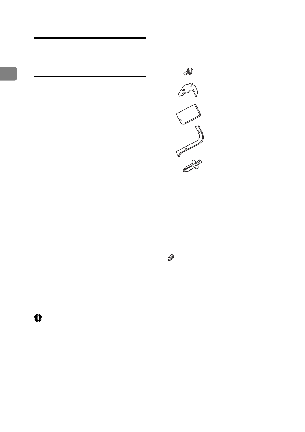
Confirm that the box contains the
A
following items.
1
2
3
4
5
6
Holder
1.
ZAEP382E
Remove the two small covers
D
from the top right side of the
printer.
Note
❒
The removed small covers are
no longer required.
ZAEP412E
ZAEP200E
Cover of the holder
2.
Socket screws (3 pcs)
3.
Wrench
4.
Hook
5.
Hook holder
6.
• Installation Guide
16
Page 31

Installing Options
Use a coin to remove the two
E
screws on the right side of the
printer.
Note
❒
The removed screws are no
longer required.
Use the wrench to remove the two
F
socket screws from the cover on
the right side of the printer, and
remove the cover.
ZAEP511E
Use the wrench to fasten the four
H
socket screws in the order as
shown in the illustration (A - D),
to secure the holder to the printer.
Important
❒
The order to fasten the screws
is, top right, top left, bottom
right and bottom left as viewed
from the right side of the printer. If the screws were not fastened in that order, the duplex
unit might not close completely
or the bypass tray might not
work correctly.
1
Note
❒
The removed screws and cover
are no longer required.
Mount the brackets of the holder
G
by placing them in the printer and
pushing downwards slightly.
ZAEP510E
Remove the small cover on the
I
right side of the printer.
Note
❒
The removed small cover is no
longer required.
ZAEP660E
ZAEP230E
ZAEP210E
17
Page 32

Setting Up the Printer
1
Mount the brackets in the holes in-
J
side of the cover that was opened
in step I. Use the wrench to fasten
the socket screw, to secure the
hook to the printer.
Lower the duplex unit so that the
K
groove in each arm of the unit
forms a joint with the pin inside
the holder as shown in the illustration.
ZAEP231E
Close the duplex unit.
M
Note
❒
If the duplex unit is not closed
completely, the holder was not
installed properly in step H. Fasten the socket screws securely in
the order described in step H.
Attach the connector of the du-
N
plex unit to the socket.
ZAEP270E
18
Hang the support bar in the du-
L
plex unit on to the hook that was
attached in step J (A), and secure
the bar by attaching the holder to
the joint (B).
ZAEP250E
ZAEP260E
If the bypass tray is not attached,
O
attach the cover of the holder. Use
the wrench to fasten the two socket screws in the order as shown in
the illustration to secure the holder to the cover.
ZAEP280E
ZAEP220E
Page 33

Installing Options
Note
❒
When attaching the bypass tray,
the cover of the holder is not required.
❒
Keep the wrench in the wrench
house inside of the front cover.
❒
After installed the last option
that you want, print a configuration page to confirm the installation. If the new device is
listed in the column of configuration options, then it has been
properly installed. For more information on printing a configuration page, see P.37 “Printing
a Configuration Page”.
ZAEP540E
Installing Bypass Tray Type
270
Preparation
The installation procedure for installing the bypass tray when the
duplex unit is not yet installed is
described below.
If the duplex unit is already installed, remove the holder cover.
Note
❒
If you install the duplex unit and
the bypass tray unit, the duplex
unit must be installed first.
❒
If the duplex unit is already installed, perform steps A to C and
then go to step I.
Confirm that the box contains the
A
following items.
1
1
2
3
Holder
1.
Socket screws (2 pcs)
2.
Wrench
3.
• Installation Guide
Note
❒
If the duplex unit is already installed, the holder is no longer
required. Go to step H.
ZAEP430E
19
Page 34

Setting Up the Printer
1
Turn off the printer, and remove
B
all cables and cords from the
printer.
Remove the adhesive tape and the
C
packing materials.
Important
❒
Don't remove the adhesive tape
(A) that is holding the tray and
cable, until the bypass tray is attached in step K.
ZAEP420E
Remove the two socket screws
E
holding the cover on the right side
of the printer using the included
wrench, and remove the cover.
Note
❒
The two removed socket screws
and the detached cover are no
longer required.
Mount the brackets of the holder
F
by placing them in the printer and
pushing downwards slightly.
ZAEP510E
20
Use a coin to remove the two
D
screws of the right side of the
printer.
Note
❒
The removed small covers are
no longer required.
ZAEP530E
ZAEP201E
Use the wrench to fasten the four
G
socket screws in the order shown
in the illustration (A - D), to secure the holder to the printer.
ZAEP210E
ZAEP660E
Page 35

Installing Options
Important
❒
The order to fasten the screws
is, top right, top left, bottom
right and bottom left as viewed
from the right side of the printer. If the screws were not fastened in that order, the duplex
unit might not close completely
or the bypass tray might not
work correctly.
If the duplex unit is not installed,
H
skip this step, and go to step I. If
the duplex unit is installed, the
plastic edges on each side of the
unit must be removed. The edges
are held in place by four small
posts. Twist the edges to break
the posts and remove them from
the unit.
Use the wrench to attach the by-
J
pass tray to the holder. Fasten the
screws in the order shown in the
illustration.
Remove the adhesive tape hold-
K
ing the bypass tray and cable, and
attach the connector to the socket
on the left bottom side of the back
of the printer.
1
ZAEP310E
Slide the bypass tray into the
I
printer aligning the grooves of
the right and left sides of the bypass tray onto the rails inside the
holder.
ZAEP290E
ZAEP300E
Note
❒
Keep the wrench in the wrench
house inside of the front cover.
Only one wrench can be kept in
the wrench house.
ZAEP320E
ZAEP541E
21
Page 36

1
R
Setting Up the Printer
❒
After installed the last option
that you want, print a configuration page to confirm the installation. If the new device is
listed in the column of configuration options, then it has been
properly installed. For more information on printing a configuration page, see P.37 “Printing
a Configuration Page”.
Installing CS370 (Mailbox)
CAUTION:
When lifting the machine, use
•
the grips on both sides. The machine could break or cause an injury if dropped.
Turn off the printer, and remove
B
all cables and cords from the
printer.
Remove the adhesive tape.
C
If you installed the duplex unit,
D
open the duplex unit by lifting
the catch.
ZAEP440E
Note
❒
If you install the mailbox, the interchange unit must be installed first.
❒
If you install the mailbox and the
paper feed unit, the paper feed
unit is recommended to be installed first.
Confirm that the box contains the
A
following items.
1
2
ZAEP383E
Open the right cover by lifting the
E
catch.
ZAEP330E
ZAEP271E
Mailbox output trays (4 pcs)
1.
Screws (2 pcs)
2.
• Installation Guide
• Output tray number seal
22
Page 37

Installing Options
If the cover of the interchange
F
unit is attached, remove it by sliding it out toward the back of the
printer.
Note
❒
If the cover of the interchange
unit is already removed, go to
step G.
❒
The removed cover is no longer
required.
Hold the mailbox on both sides
G
and insert it into the printer from
the top side of the printer.
ZAEP710E
Fasten the two screws by hand
H
and secure the mailbox to the
printer. Use a coin to fasten the
screws securely.
Close the right cover by pushing
I
the area as shown in the illustration.
1
ZAEP350E
ZAEP340E
If the duplex unit is already at-
J
tached, close the unit.
Slide the four mailbox output
K
trays into the lower side of the
mailbox first.
ZAEP690E
ZAEP360E
23
Page 38

Setting Up the Printer
1
Note
❒
After installed the last option
that you want, print a configuration page to confirm the installation. If the new device is
listed in the column of configuration options, then it has been
properly installed. For more information on printing a configuration page, see P.37 “Printing
a Configuration Page”.
Installing Printer Feature
Expander Type 185
Important
❒
The memory unit can be damaged
by small amounts of static electricity. Before touching it, ground
yourself by touching something
metal to remove static electricity
from you.
Note
❒
If you install Printer Feature Expander Type 185 and Printer Hard
Disk Type 185, Printer Feature Expander Type 185 must be installed
first.
Confirm that the box contains the
A
following item.
• Memory
Turn off the printer, and remove
B
all cables and cords from the
printer.
Use a coin to remove the six
C
screws, and remove the printer
board cover.
Note
❒
The removed cover and screws
are required in step E.
ZAEP010E
24
Page 39

Tilt the memory unit so that it is
D
30 degrees perpendicular to the
slot (A), and push it forward (B).
It should make click into place.
Note
❒
If the hard disk is already installed, remove the hard disk
first.
Attach the printer board cover
E
that was removed in step C, and
use a coin to fasten the six screws.
ZAEP020E
Installing Options
Installing Printer Hard Disk
Type 185
Important
❒
The hard disk can be damaged by
small amounts of static electricity.
Before touching it, ground yourself by touching something metal
to remove static electricity from
you.
Confirm that the box contains the
A
following items.
• Hard disk
• Installation Guide
Turn off the printer, and remove
B
all cables and cords from the
printer.
Use a coin to remove the six
C
screws, and remove the printer
board cover.
1
Note
❒
If you continue to install the
hard disk, it is not necessary to
reattach the cover.
❒
After installed the last option
that you want, print a configuration page to confirm the installation. If the new device is
listed in the column of configuration options, then it has been
properly installed. For more information on printing a configuration page, see P.37 “Printing
a Configuration Page”.
ZAEP011E
Note
❒
The removed cover and screws
are required in step G.
ZAEP013E
25
Page 40

Setting Up the Printer
1
Use a coin to remove the two
D
screws, and remove the cover.
Note
❒
The removed screws are required in step F.
❒
The removed cover is no longer
required.
Align the hard disk interface con-
E
nector over the printer interface
port, and push gently but firmly
on the hard disk until it is completely connected.
ZAEP561E
Attach the printer board cover
G
that was removed in step C, and
use a coin to fasten the six screws.
Note
❒
After installed the last option
that you want, print a configuration page to confirm the installation. If the new device is
listed in the column of configuration options, then it has been
properly installed. For more information on printing a configuration page, see P.37 “Printing
a Configuration Page”.
ZAEP014E
26
Fasten the two screws that were
F
removed in step D to attach the
hard disk to the printer.
ZAEP571E
ZAEP581E
Page 41

Installing the Toner Bottle
R
R
WARNING:
•
Do not incinerate spilled
toner or used toner. Toner
dust is flammable and
might ignite when exposed
to an open flame.
•
Disposal should take place
at an authorized dealer or
an appropriate collection
site.
•
If you dispose of the used
toner containers yourself,
dispose of them according
to local regulations.
CAUTION:
The inside of the machine be-
•
comes very hot. Do not touch
the parts with a label indicating a "hot surface". Touching
a "hot surface" could result in
a burn injury.
Do not eat or swallow toner.
•
Keep toner (used or unused)
•
and the toner cartridge out of
reach of children.
Open the front cover.
A
Lift the green handle.
B
While pushing the green lever
C
(A), hold the handle and slide the
toner holder out slightly (B).
Installing the Toner Bottle
1
ZAET010E
ZAET020E
Our products are engineered
•
to meet the highest standards
of quality and functionality.
When purchasing expendable
supplies, we recommend using only those provided by an
authorized dealer.
ZAET021E
27
Page 42

Setting Up the Printer
1
Release the green lever and slide
D
the toner holder out until it stops
gently.
Important
❒
If you continue to push the
green lever to slide the toner
holder, the toner holder might
drop.
Move the new toner bottle back
E
and forth about 5 - 6 times (A),
and remove the black cap of the
new toner bottle by turning it
counterclockwise (B).
Slide the toner holder into the
G
printer until it clicks into place,
and push the green handle down.
Close the front cover.
H
ZAET022E
Important
❒
Do not remove the inside cap.
Note
❒
After removing the black cap
from the bottle, toner can scatter
easily. Do not shake or jar the
bottle.
Put the toner bottle on the toner
F
holder (A), then push its head
downwards to lock it in place (B).
ZAET030E
28
ZAET040E
Page 43

Loading Paper
Loading Paper
This section describes the type, size,
feed direction, and maximum capacity of paper that can be loaded into
each paper tray in this printer.
Reference
For more information on the size
and feed direction of paper that
can be set in the tray, see "Paper
Type and Sizes" in the "Printer Reference."
Loading Paper on the Paper
Tray
This section describes instructions for
loading paper in the standard paper
tray and optional PS400 or PS440. If
you want to load paper in PS420, see
P.31 “Loading Paper on PS420 (Paper
Feed Unit)”. If you want to load paper
in Bypass Tray Type 270, see P.32
“Loading Paper on Bypass Tray Type
270”.
Set the paper guide lock to the
B
“unlocked” position.
Important
❒
Confirm that the lever of the
side guide is released before
sliding this guide, otherwise it
can be damaged.
Slide the side paper guide wide
C
open (B) by pressing the release
lever of the side guide (A).
1
ZAEY011E
Slide the paper tray out until it
A
stops.
ZAEY020E
ZAEY010E
29
Page 44

Setting Up the Printer
1
Align all four sides of the paper
D
stack, and load it into the tray.
Important
❒
Do not stack paper over the limit mark.
❒
When you set thick paper in tray
2, do not stack paper above the
lower limit mark (A) of tray 2.
ZAEY030E
Align the side guide for the load-
E
ed paper size (B) by opening the
release lever of the side guide
(A).
Set the paper guide lock to the
F
“locked” position.
ZAEY031E
Note
❒
Shuffle the paper before setting
in the tray.
❒
Load the paper face up onto the
tray.
ZAEY052E
Align the rear guide for the load-
G
ed paper size slightly by pushing
the releasing lever of the rear
guide.
ZAEY032E
ZAEY033E
30
Page 45

Adjust the paper size dial for
H
loaded paper size.
Loading Paper
Loading Paper on PS420
(Paper Feed Unit)
Important
❒
Confirm that the setting of the
paper size dial matches the paper size and feed direction of
the paper in the tray. Otherwise,
the paper misfeed or unexpected printing result might occur.
❒
When the actual paper size is
not shown on the dial, set the
dial to "p" and specify the paper size using the operation
panel. For more information on
setting up the paper size, see
"Paper and Other Media" in the
"Printer Reference".
ZAEY050E
Reference
For more information on the size
and feed direction of paper that
can be set in the tray, see "Paper
Type and Sizes" in the "Printer Reference".
Note
❒
Load paper that is the same size on
the right and left sides of the paper
feed unit.
Slide the paper tray out until it
A
stops.
1
ZAEY200E
Note
❒
Thick paper can be set in tray 2 of
the printer or Bypass Tray Type
270. For more information on
loading paper in the bypass tray,
see P.32 “Loading Paper on By-
pass Tray Type 270”. When thick
paper is placed on tray 2, change
the lever on the paper size dial of
tray 2 of the printer to the “Thick
paper” mode. For more information on loading paper, see "Loading Thick Paper, Envelope or
OHP Transparencies" in the
"Printer Reference".
Slide the tray into the printer un-
I
til it stops.
Load paper completely into the
B
tray.
ZAEY201E
31
Page 46

Setting Up the Printer
1
Important
❒
Align paper to each side completely.
❒
Do not stack paper over the limit mark.
❒
Confirm that the end fence locks
completely after loading the
right side paper.
❒
If you want to change the paper
size, contact your sales or service representative.
Note
❒
Shuffle the paper before setting
in the tray.
❒
Load the paper face up onto the
tray.
❒
If either side or the leading edge
of paper is curled, straighten it,
and then load it.
Slide the tray into the printer un-
C
til it stops.
Loading Paper on Bypass Tray
Type 270
Open the bypass tray.
A
Lift the paper guide lever.
B
Important
❒
If the paper guides do not
match the paper size, a skew
image or a paper misfeed might
occur.
ZAEY040E
ZAEY210E
32
Note
❒
The supported size of the bypass
tray is approximately 90 - 297 mm
(3.54" - 11.69") in width, and approximately 148 - 432 mm (5.83" -
17.00") in length.
❒
To set the custom size with the operation panel, see "Specifying the
Custom Paper Size for the Bypass
Tray" in the "Printer Reference".
❒
If you load a custom or unique paper size, set the paper size using
the operation panel.
❒
If thick paper, OHP transparencies
or envelopes are loaded, set the
printer to the “Thick paper” mode
using the printer driver.
Note
❒
Swing out the extender to support paper sizes longer than A4
short-edge feed (Metric version)
1
or 8
/
" × 11" short-edge feed
2
(Inch version).
Page 47

Loading Paper
Load the paper, and adjust the pa-
C
per guides to the sides of the paper.
Important
❒
Confirm the print side of the
OHP transparencies. Some
OHP transparencies can be
printed on only the specific
side.
Note
❒
Do not stack paper over the limit mark. Otherwise a skew image or a paper misfeed might
occur.
❒
Set the paper after shuffling
through the sheets.
❒
Load the paper face down onto
the tray.
❒
When you set custom size or
thick paper in the bypass tray,
do not stack paper above the
lower limit mark of the bypass
tray.
ZAEY220E
Push down the paper guide lever.
D
Note
❒
If the paper guide lever is not
pushed down, paper misfeed
might occur.
Turn on the printer.
E
Reference
For more information on turning on the printer, see P.35
“Connecting the Power Cord”.
Configure the paper feed unit di-
F
rection and the paper size.
Important
❒
The paper size specified with
the printer driver overrides the
one specified here.
Reference
For more information on specifying the bypass tray, see the
printer driver help.
For more information on loading custom paper, see “Loading
Paper and other Media” in the
“Printer Reference”.
Press
A
The following message appears
on the panel display.
{
Menu
.
}
1
ZAEY250E
Main Menu:
Proof Print
33
Page 48

Setting Up the Printer
1
Press
B
lowing message appears.
{T}
or
until the fol-
{U}
Main Menu:
Job Control
Press
C
The following message appears
on the panel display.
{
Enter
.
}
Job Control:
Paper Input
Press
D
The following message appears
on the panel display.
{
Enter
.
}
Paper Input:
Tray Priority
Press
E
lowing message appears.
{T}
or
until the fol-
{U}
Press
I
The following message appears
on the panel display.
{
Enter
.
}
Standard Size:
*8 x 13
Note
❒
“p” shown in front of an
item indicates that the item is
currently selected.
After the panel display chang-
J
es, press
The panel display returns to the
ready condition as follows:
{
Menu
.
}
Ready
Paper Input:
Bypass Size
Press
F
The following message appears
on the panel display.
{
Enter
.
}
Bypass Size:
Standard Size
Press
G
The following message appears
on the panel display.
{
Enter
.
}
Standard Size:
11 x 8 1/2
Press
H
Standard size.
{T}
or
to select the
{U}
34
Page 49

Connecting the Power Cord
R
CAUTION:
Do not handle the plug with wet
•
hands. Doing this might cause
an electrical shock.
Confirm that the power is turned
A
off. If it is on, turn it off.
ZAEH220E
Connecting the Power Cord
1
Insert the plug of the power cord
B
securely into the printer.
Insert the plug of the power cord
C
securely into the wall outlet.
Important
❒
Confirm that the printer is
turned off when you insert or
pull the plug of the power cord.
Turn on the printer.
D
ZAEH221E
35
Page 50

Setting Up the Printer
Selecting the Panel Display Language
1
Note
❒
You can select one of the following
languages: English, German,
French, Italian, Dutch, Swedish,
Norwegian, Danish, Spanish,
Finnish, Portuguese, Czech, Polish, or Hungarian.
❒
The default setting is English.
❒
If you want to use the English panel display, it is not necessary for
you to do the following procedures.
Press
A
The following message appears on
the panel display.
{
Menu
.
}
Main Menu:
Proof Print
Press
B
ing message appears.
{T}
or
until the follow-
{U}
Press
D
language you want to select.
{T}
or
to display the
{U}
Language:
French
Press
E
The following message is displayed on the panel display for
two seconds, and then the panel
display automatically returns to
the main menu.
{
Enter
.
}
Language:
*French
36
Main Menu:
Language
Press
C
The following message appears on
the panel display.
{
Enter
.
}
Language:
*English
Note
❒
“p” shown in front of an item
indicates that the item is currently selected.
Page 51

Printing a Configuration Page
Printing a Configuration Page
You can confirm that the current configuration of the printer by printing a
configuration page.
Reference
For more information on the items
of a configuration page, see P.38
“Interpreting a Configuration Page”.
Press
A
The following message appears on
the panel display.
{
Menu
.
}
Main Menu:
Proof Print
Press
B
ing message appears on the panel
display.
{T}
or
until the follow-
{U}
Main Menu:
List Print
Important
❒
If you cannot complete the
printing a configuration page
correctly, check if an error message appears on the panel display. For more information on
error messages, see "Error &
Status Messages on the Operation Panel" in the "Printer Reference."
1
Press
C
The following message appears on
the panel display.
{
Enter
.
}
List Print:
Config. Page
Press
D
The following message appears on
the panel display.
{
Enter
.
}
Config. Page:
Press Enter (#)
Press
E
In a short time, the printing a configration page will start.
{
Enter
.
}
37
Page 52

1
Setting Up the Printer
Interpreting a Configuration Page
Reference
❖
Printer ID
Shows the serial number of the printer.
❖
Firmware Version
Shows the version number of the printer firmware.
❖
Pages Printed
Shows the total number of pages printed.
Memory
❖
Total Memory
Shows the total amount of memory installed on the printer.
❖
Proof Print Total Memory
Shows the total amount of hard disk space that is available for proof print
jobs.
❖
Proof Print Free Memory
Shows the amount of hard disk space that is available for proof print jobs.
❖
Font Download Total Memory
Shows the total memory used by the downloaded fonts.
❖
Font Download Free Memory
• Total Memory
Shows the amount of memory that is available for font downloads.
• Free Memory
Shows the amount of hard disk space that is available for font downloads.
Options
Shows the options installed on the printer.
Job Control
Shows the settings you make with the “Job Control” menu.
Reference
For more information on the “Job Control”, see “Job Control Menu” in the
“Printer Reference”.
38
Page 53

Interpreting a Configuration Page
Network Setup
Shows the settings you make with the “Network Setup” menu and your computer.
Reference
For more information on the “Network Setup”, see “Network Setup” in the
“Printer Reference”.
Maintenance
Shows the settings you make with the “Maintenance” menu.
Reference
For more information on the “Maintenance”, see “Maintenance Menu” in the
“Printer Reference”.
Language
Shows the settings you select with the “Language” menu.
1
Reference
For more information on the “Language”, see “Language” in the Printer Reference.
39
Page 54

Setting Up the Printer
Connecting the Printer
1
Requirements
Requirements
Before using this printer, confirm that all the environmental and electrical requirements have been met. Connect the printer to your host computer using the
parallel port, 10BASE-T/100BASE-TX port, or both.
Confirm that all the cables, connectors, and electrical outlets necessary to attach
the printer to your host computer or network are present.
Important
❒
The interface cable is not supplied in the box. It is your responsibility to provide the interface cable appropriate for the computer that you are using.
❒
It comes standard with network-ready Ethernet capability (Network Interface Board 185).
Reference
For more information on using the parallel port, see P.44 “Connecting the
Printer to the Host Using a Parallel Cable”.
For more information on using a network, see P.42 “Connecting the Printer to
the Network”.
Network Cable Requirements
Network Interface Board supports 10BASE-T or 100BASE-TX connections.
You can use the printer in the following network environments:
• Use the appropriate network management software and printer driver.
• Attach the printer to a networked computer set up as a server.
Client
Driver
File Server
Protocol
*1
With Windows NT 4.0, only x86 based computers are supported.
*2
Under the Windows 95/98/NT 4.0 only.
Windows 95, 98, NT 4.0
PCL 6/5e , PostScript 3
NetWare 3.x, NetWare 4.x, NetWare 5
TCP/IP, IPX/SPX, NetBEUI
*1
, 3.1x, Macintosh
*2
, AppleTalk
40
Page 55

Connecting the Printer
In a mixed network environment, the protocol switches automatically.
Reference
For more information on configuring the Network Interface Board 185, see
the “Operating Instructions” that comes with it.
For more information on resolving network connection problems, see "Troubleshooting" in the "Printer Reference".
Note
❒
Consult your network administrator before connecting your printer to a network.
❒
In a 100BASE-TX environment, be sure to use properly shielded and grounded cable (STP, Category/Type5) for the connection to your host computer
(and/or HUB) in order to meet FCC and EMC Directive 89/336/EEC emission guidelines.
Parallel Cable Requirements
Connect the printer to your host computer using a parallel port. A parallel cable
to connect the printer to the host computer is not included with this printer.
1
The printer's parallel interface is a standard bi-directional interface. It requires a
standard 36-pin parallel cable compliant with IEEE 1284 and a parallel port
available on the host computer.
Note
❒
Do not use a parallel cable that is longer than 3 meters (10 feet).
41
Page 56

1
Setting Up the Printer
Connecting the Printer to t he Network
Connect the printer to the network using Network Interface Board 185 which is
built in as standard.
Follow these steps to connect the printer.
Confirm that you have the correct cable.
A
Confirm that the printer is turned off.
B
Loop the network cable. The loop should be about 10cm (4”) from the end
C
of the cable on the end closest to the printer.
Attach the ferrite core to the loop.
D
ZAEH250E
Attach the network cable to the 10BASE-T/100BASE-TX port of the printer.
E
ZAEP370E
Reference
See "Guide to the Printer" in the "Printer Reference" to confirm the position
of the 10BASE-T/100BASE-TX port.
Note
❒
Confirm that the cable is connected to the 10BASE-T/100BASE-TX port.
Connect the other end of the cable to the network.
F
42
Page 57

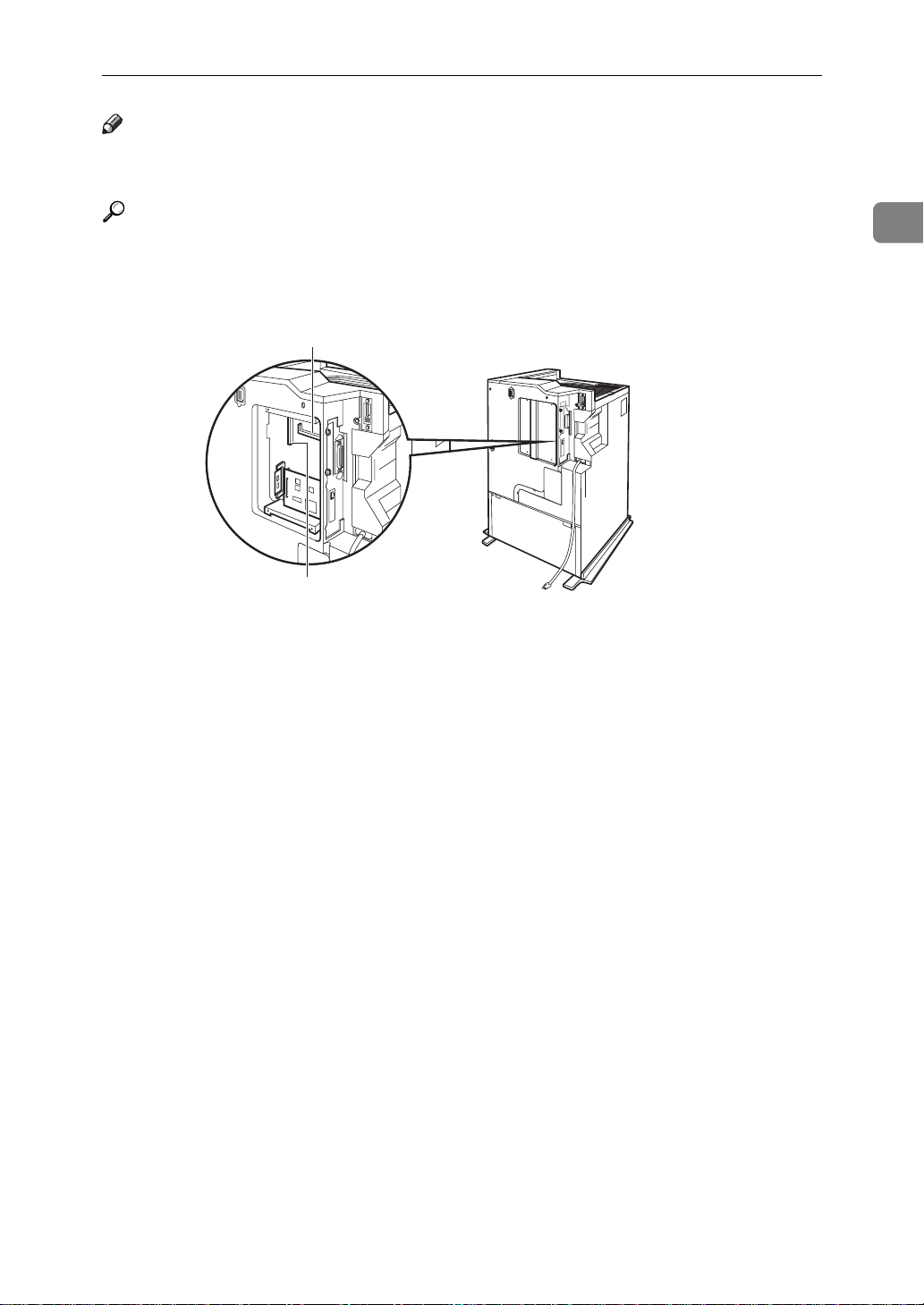
Button and Indicators on the Network Interface Board
1
2
3
4
Connecting the Printer
1
ZAEX010E
Indicator (green)
1.
Stays on while the printer is in a network
environment.
Indicator (green)
2.
Stays on while 100BASE-TX is working.
Stays off while 10BASE-T is working.
Indicator (orange)
3.
Stays on while the network interface
board is working.
Button
4.
Press this button for more than 2 seconds
to print “Network Configuration Page”.
Press this button for more than 5 seconds
to print the “System Log Information”.
43
Page 58

1
Setting Up the Printer
Connecting the Printer to the Host Using a Parallel Cable
Connect the printer to the host computer using a parallel cable compliant with
IEEE 1284.
Follow these steps to connect the printer to your host computer.
Confirm that you have the correct cable.
A
Confirm that both the printer and the host computer are turned off.
B
Plug the 36-pin end of the parallel cable into the parallel port of the printer.
C
ZAEH231E
Reference
See "Guide to the Printer" in the "Printer Reference" to confirm the position
of the parallel port.
Squeeze the wire clips on each side of the connector together until they
D
snap into place. The clips hold the cable securely in place.
Plug the other end of the parallel cable into the computer's parallel port.
E
44
Page 59

2. Configuring the Printer for
the Network
Configuring the Printer for the Network
with the Operation Panel
Reference
This printer contains Network Interface Board 185 as a standard.
For more information on configuring for a network, see the "Operating Instructions" for the Network
Interface Board which is included
in the CD-ROM.
To use the network interface board,
configure it for the network using the
printer's operation panel.
The following table shows the operation panel settings and their default
settings. These are included in the
“Main Menu”.
Items Default
32 IP Address 011.022.033.044
33 Subnet Mask 000.000.000.000
34 Gateway Ad-
dress
000.000.000.000
Press
A
The following message appears on
the panel display.
{
Menu
.
}
Main Menu:
Proof Print
Press
B
ing message appears.
{T}
or
until the follow-
{U}
Main Menu:
Network Setup
Press
C
The following message appears on
the panel display.
{
Enter
.
}
Network Setup:
IP Address
35 Access Control
(Access Control
Address)
36 Access Mask
(Access Control
Mask)
37 Network Boot None
38 Frame
Type(NW)
(Frame Type
NetWare)
39 ActiveProtocols All Active
000.000.000.000
000.000.000.000
Auto Select
45
Page 60

Configuring the Printer for the Network
2
Use the following table to select
D
the menu item appropriate for
your network.
Menu item on
the panel
display
All Active
(Default Setting)
None
TCP/IP Only
NetWare Only
TCP/IP & NetW
ATalk Only
TCP/IP & ATalk
NetWare & ATalk
TCP & NW & ATK
NetBEUI only
TCP/IP & NB
NetBEUI & NetW
TCP & NB & NW
NetBEUI & ATalk
TCP & NB & ATK
NB & NW & ATalk
Active Protocol
*1
*2
TCP
NW
''''
'
'
''
''
''
'''
''
''
'' '
'''
'''
*3
AT
'
''
NB
B
Press
{
Enter
.
}
The following message appears
on the panel display.
*4
ActiveProtocols:
*All Active
Note
❒
“p” shown in front of an
item indicates that the item is
currently selected.
C
Press
{T}
or
until the pro-
{U}
tocols you want to use appears.
D
Press
{
Enter
.
}
The actual procedure may differ
depending on the protocol you
use. Follow the appropriate
'
procedure.
TCP/IP E V F V G V H V J
NetWare I V J
AppleTalk J
NetBEUI J
46
•' means that this protocol is active.
• Blank cell means that this protocol is not active.
*1
TCP/IP
*2
NetWare
*3
AppleTalk
*4
NetBEUI
Note
❒
You should not select protocols
that are not used on your network.
A
Press
{T}
or
until the fol-
{U}
lowing message appears.
Network Setup:
ActiveProtocols
Page 61

Configuring the Printer for the Network with the Operation Panel
If you use TCP/IP, you should as-
E
sign the IP Address to your printer.
Note
❒
To get the IP Address for your
printer, contact your network
administrator.
❒
The IP Address is shown by
Byte on the panel display.
A
Press
{T}
or
until the fol-
{U}
lowing message appears.
Network Setup:
IP Address
Press
B
{
The current Byte 1 of the IP Address appears on the panel display.
Enter
.
}
IP Address:
Byte 1= 11
Use
C
IP Address.
Press
D
The current Byte 2 of the IP Address appears.
{U}
{
or
Enter
to specify the
{T}
.
}
IP Address:
Byte 2= 22
Use
E
Byte 2 of the IP Address.
Repeat steps C and D to specify the rest of the IP Address.
Press
F
Address you specified.
{U}
{
or
Enter
to specify the
{T}
to register the IP
}
If you use TCP/IP, you should as-
F
sign the “Subnet Mask” and
“Gateway Address” using the
same procedure for specifying the
IP Address.
If you use TCP/IP, set the “Access
G
Control” and “Access Mask” using the same procedure for specifying the IP Address, if necessary.
If you use TCP/IP, you can make
H
settings for “Network Boot”.
You can select how to assign the
printer's address using the computer. Select one of the items on
the following table.
Menu item on
the panel
display
ARP + PING
ARP & RARP
ARP & BOOTP
ARP&RARP&
BOOTP
None
(Default Setting)
RARP + TFTP
BOOTP
RARP & BOOTP
DHCP
*1
ARP + PING
*2
RARP + TFTP
*3
BOOTP
*4
DHCP
Available method
*1
*2
BO
*3
'
RA
AR
'
''
''
'''
'
''
Note
❒
You should set up your server,
if you want to use “RARP +
TFTP”, “BOOTP”, or “DHCP”.
A
Press
{T}
or
until the fol-
{U}
lowing message appears.
Network Setup:
Network Boot
DH
2
*4
'
47
Page 62

Configuring the Printer for the Network
2
Press
B
The current setting appears on
the panel display.
{
Enter
.
}
Network Boot:
*None
Use
C
od you want to use appears.
Press
D
If you use NetWare, select the
I
frame type for NetWare.
Select one of the items below if
necessary.
• Auto Select (Default)
• Ethernet 802.3
• Ethernet 802.2
• Ethernet II
• Ethernet SNAP
Note
❒
Usually, you can use the default
setting (“Auto Select”). With
“Auto Select”, the frame type
detected by the printer first is
adopted. If your network can
use more than two frame types,
the printer may fail to select the
correct frame type. In this case,
select the appropriate frame
type.
Press
A
lowing message appears.
{T}
{
{T}
or
Enter
or
until the meth-
{U}
.
}
until the fol-
{U}
Network Setup:
Frame Type(NW)
Press
B
The current setting appears on
the panel display.
{
Enter
.
}
Network Setup:
*Auto Select
Use
C
type you want to use appears.
Press
D
Exit from the setup menu to the
J
available function settings.
Press
A
Press
B
Press
C
If you want to confirm your
K
printer's configuration, print a
configuration page.
Press
A
The following message appears
on the panel display.
{T}
{
Enter
{
Escape
{
Escape
[
Exit
{
Menu
or
]
until the frame
{U}
.
}
.
}
.
}
.
.
}
Main Menu:
Proof Print
Press
B
lowing message appears.
{T}
or
until the fol-
{U}
Main Menu:
List Print
Press
C
The following message appears
on the panel display.
{
Enter
.
}
List Print:
Config. Page
Press
D
The following message appears
on the panel display.
{
Enter
.
}
Config. Page:
Press Enter (#)
When printing a configuration
page, you can confirm your
printer's configuration.
48
Page 63

Configuring the Printer for the Network with the Operation Panel
Address
-
❖
Subnet Mask
A number used to mathematically
"mask" or hide an IP Address on
the network by eliminating those
parts of the address that are alike
for all the printers on the network.
❖
Gateway Address
A gateway is a connection or interchange point that connects two
networks. A gateway address is for
the router or host computer used
as a gateway.
Note
❒
To get the addresses, contact
your network administrator.
❖
Access Control Address and Access
Control Mask
Access Control Address and Access Control Mask are used to control the IP Addresses that have
access to the computer used for
printing, with the IP Address. If it
is not necessary for you to control
the access rights, select “0.0.0.0”.
Access Control
Mask
0. 0. 0. 0 XXX.XXX.XXX.XXX
255. 0. 0. 0 192.XXX.XXX.XXX
255.255. 0. 0 192.168.XXX.XXX
255.255.255. 0 192.168. 15.XXX
255.255.255.255 192.168. 15. 16
IP Address that
have access
2
Note
❒
When the Access Control Address settings coincide with the
masked result of the IP Address
of the computer, print jobs from
that IP Address can be accepted
by the network interface board.
❒
For example, if you assign
192.168.15.16 as the Access Control Address to the network interface board, the combination
of the Access Control Mask and
IP Address that can have access
are as follows. (xxx: for any numerical value)
49
Page 64

2
Configuring the Printer for the Network
50
Page 65

3. Installing the Printer Driver
and Software
All of the procedures in this manual assume that you are familiar with general
Windows procedures and practices. If you are not, see the documentation that
comes with Windows for details.
Auto Run
You can install the printer driver by using Auto Run.
Auto Run is available for the following operating systems:
• Windows 95/98
• Windows NT 4.0
If your system is Windows 3.1x or Macintosh, see information on installing the
printer driver.
⇒ P.55 “Windows 95/98 - Installing the PCL 6/5e Printer Driver”.
⇒ P.56 “Windows 3.1x - Installing the PCL 6/5e Printer Driver”.
⇒ P.62 “Macintosh”.
Important
❒
Before starting this installation, close all documents and applications. In a network environment, confirm that users who are logged on are disconnected.
Be sure to do this when it will create the least interference with other users.
❒
After installing a printer driver, you must restart the computer.
Limitation
❒
If your system is Windows NT 4.0, installing a printer driver requires Full
Control access permission. Members of the Administrators, Server Operators,
Print Operators, and Power Users groups have Full Control permission by
default. When you install a printer driver, log on under Full Control permission.
Reference
For more information on the software and utilities included on the CD-ROM,
see P.53 “Software and Utilities Included on the CD-ROM”.
Note
❒
Auto Run might not automatically work with certain OS settings. In this case,
start "SETUP.EXE" to install printer driver on the root.
❒
If you want to cancel Auto Run, insert the CD-ROM while pressing the
{
SHIFT
key until your computer finishes accessing the CD-ROM.
}
51
Page 66

Installing the Printer Driver and Software
Using the Shared Printer on Windows NT 4.0 for Windows 95/98 Client
-
If you want to share the printer on Windows NT 4.0, you must not install the
printer driver using Auto Run. Install the printer driver of the Windows 95/98
for alternate driver.
For more information on installing the printer driver as an alternate driver, see
P.55 “Windows NT 4.0 - Installing the PCL 6/5e Printer Driver”.
3
Installing by Auto Run
Follow these steps to install the printer driver on Windows 95/98/NT 4.0.
Important
❒
Never have two versions of the same printer driver installed on your system
at the same time. When upgrading to a new version of the printer driver, uninstall the old version, and then install the new one. For more information on
uninstalling the printer driver and software, see “Uninstalling the Printer
Driver and Software” in the Printer Reference.
Note
❒
If the "plug and play" function is started by Auto Run, click
dialog box or
[
New Hardware Found
CD-ROM.
the system version of the Windows 95/98.
❒
The appropriate language name is used in the CD-ROM folder: ENGLISH
(English), DEUTSCH (German), FRANCAIS (French), ITALIANO (Italian),
ESPANOL (Spanish), NEDRLNDS (Dutch), NORSK (Norwegian), DANSK
(Danish), SVENSKA (Swedish), POLSKI (Polish), PORTUGUS (Portuguese),
SUOMI (Finnish), MAGYAR (Hungarian), CESKY (Czechoslovakian)
Close all applications that are currently running.
A
[
New Hardware Found
]
[
Device Driver Wizard
or
]
[
Device Driver Wiz ar d
, and then insert the
]
appears depending on
]
[
Cancel
]
of the
52
Insert the CD-ROM in the CD-ROM drive.
B
Follow the instructions on the screen.
C
Restart your computer after installation is complete.
D
You should set up the options with the printer driver.
E
Page 67

Software and Utilities Included on the CD-ROM
Software and Utilities Included on the CDROM
❖
Agfa Font Manager
Helps you to install new fonts, or organize and manage fonts already installed on your system.
❖
PRINTER MANAGER FOR ADMINISTRATOR
A utility for the system administrator to manage printers on the network.
Reference
For the name of the PRINTER MANAGER FOR ADMINISTRATOR you
use, see the “Operating Instruction” for the Network Interface Board
which is on the CD-ROM.
See the PRINTER MANAGER FOR ADMINISTRATOR Online Help for
details on using the PRINTER MANAGER FOR ADMINISTRATOR.
❖
PRINTER MANAGER FOR CLIENT
A utility for users to manage their own print status on the network.
Reference
For the name of the PRINTER MANAGER FOR CLIENT you use, see the
“Operating Instruction” for the Network Interface Board which is included in the CD-ROM.
See the PRINTER MANAGER FOR CLIENT Online Help for details on using the PRINTER MANAGER FOR CLIENT.
❖
Multidirect Print
A utility for printing on a "Peer-to-Peer" network.
Reference
For more information on Multidirect Print, see the “Operating Instructions” for the Network Interface Board which is included in the CD-ROM.
3
❖
PortNavi
A utility that helps you to use netork printer effectively. It is useful in environments where two or more network printers are used.
Reference
For more information on PortNavi, see the “Supplement” for the Network
Interface Board which is included in the CD-ROM.
❖
Acrobat Reader
A utility that allows you to read PDF (Portable Document Format).
53
Page 68

3
Installing the Printer Driver and Software
Note
❒
Documentation on using the printer is included on the CD-ROM in PDF
format.
54
Page 69

Installing the PCL 6/5e Printer Driver
Installing the PCL 6/5e Printer Driver
Windows 95/98 - Installing t he PCL 6/5e Printer Driver
Installing the Printer Driver
Install the driver in accordance with the steps explained. ⇒ P.52 “Installing by
Auto Run”
Setting Up Options
Note
❒
When setting up options, you should access the Printer Properties from Windows. You cannot access the Printer Properties from an application.
3
Click
A
The
[
Printers
Click the icon of the printer you want to use. On the
B
[
Properties
Click the
C
Select any options you have installed from the
D
Click
E
on the task bar, point to
[
]
Start
window appears.
]
.
]
[
Accessories
.
[
]
OK
tab.
]
[
Settings
, and then click
]
[
File
[
Options
group.
]
[
Printers
menu, click
]
.
]
Windows NT 4.0 - Installing the PCL 6/5e Printer Driver
Installing the Printer Driver
Install the driver in accordance with the steps explained. ⇒ P.55 “Windows 95/98
- Installing the PCL 6/5e Printer Driver”
If you want to share the printer on Windows NT 4.0, you must not install the
printer driver using Auto Run. In this case, cancel Auto Run and install the
printer driver using
When prompted for Windows NT 4.0 alternate driver location, specify the following folder in the CD-ROM.
[
Add Printer Wizard
in the
]
[
Printers
window.
]
• PCL 5e
\DRIVERS\PCL5E\NT4\(Lauguage)\DISK1\
• PCL 6
\DRIVERS\PCL6\NT4\(Lauguage)\DISK1\
55
Page 70

3
Installing the Printer Driver and Software
When prompted for Windows 95/98 alternate driver location, specify the following folder in the CD-ROM.
• PCL 5e
\DRIVERS\PCL5E\WIN95_98\(Lauguage)\DISK1\
• PCL 6
\DRIVERS\PCL6\WIN95_98\(Lauguage)\DISK1\
Setting Up Options
Limitation
❒
Changing the setting of the printer requires Full Control access permission.
Members of the Administrators, Server Operators, Print Operators, and Power Users groups have Full Control permission by default. When you set up
options, log on under Full Control permission.
Note
❒
When setting up options, you should access the Printer Properties from Windows. You cannot access the Printer Properties from an application.
Click
A
The
[
Printers
Click the icon of the printer you want to use. On the
B
[
Properties
Click the
C
Select any options you have installed from the
D
Click
E
on the task bar, point to
[
]
Start
window appears.
]
.
]
[
Accessories
.
[
]
OK
tab.
]
[
Settings
, and then click
]
[
File
[
Options
group.
]
[
Printers
menu, click
]
Windows 3.1x - Installing the PCL 6/5e Print er Driver
Installing the Printer Driver
Important
❒
We recommend you to install the PCL 5e printer driver on your Windows
3.1x system. Under Windows 3.1x system, you might get some unexpected
print results with the PCL 6 printer driver.
Close all the applications that are currently running.
A
.
]
56
Insert the CD-ROM in the CD-ROM drive.
B
C
From
[
Program Manager
, click
]
[
Run
on the
]
[
File
menu.
]
Page 71

Installing the PCL 6/5e Printer Driver
In the
D
Select the CD-ROM drive in the
E
Open
F
Open
G
Open the folder of the language you use.
H
Open
I
Double-click “SETUP.EXE”.
J
Follow the instructions on the screen.
K
Setting Up Options
Note
❒
When setting up options, you should access the Printer Setting dialog box
from Windows. You cannot access the Printer Setting dialog box from an application.
From the
A
window, click
[
]
Run
[
Main
]
]
.
]
.
or
]
[
PCL5E
[
WIN31
[
DISK1
PCL6
.
]
[
group of
[
Browse
[
Program Manager
.
]
[
Drives:
list.
]
, double-click
]
[
Control Panel
3
.
]
Double-click the
B
In the
C
Click
D
Click the
E
The
Select any options you have installed from the
F
Click
G
Click
H
[
Installed Printers:
[
Setup
[
Accessories
[
Options
to close the Printer Setting dialog box.
[
]
OK
[
]
Close
[
Printers
.
]
group appears.
]
to close the
icon.
]
list, click the name of the printer you want to set up.
]
tab.
]
[
Printers
dialog box.
]
[
Options
group.
]
57
Page 72

3
Installing the Printer Driver and Software
Installing the PostScript Printer Driver
Windows 95/98 - Installing t he Post Script Printer Driver
Installing the Printer Driver
Install the driver in accordance with the steps explained. ⇒ P.52 “Installing by
Auto Run”
Setting Up Options
Note
❒
When setting up options, you should access the
dows. You cannot set up options when accessing the
an application.
[
Device Options
[
Device Options
tab from Win-
]
tab from
]
Click
A
The
[
Printers
Click the icon of the printer you want to use. On the
B
[
Properties
Click the
C
The
[
Installable options
From the
D
The current setting is displayed in the
Use the
E
ed option.
Click
F
After making all settings you want, click
G
on the task bar, point to
[
]
Start
window appears.
]
.
]
[
Device Options
[
Installable options
[
Change setting for:
[
to apply the settings you made.
]
Apply
]
group appears.
]
[
Settings
tab.
box, select the option you have installed.
]
[
Change settings for:
list to select the appropriate setting for the select-
]
, and then click
]
.
[
]
OK
[
Printers
menu, click
[
]
File
list.
]
Windows NT 4.0 - Installing the PostScript Printer Driver
Installing the Printer Driver
.
]
Install the driver in accordance with the steps explained. ⇒ P.52 “Installing by
Auto Run”
58
Page 73

Installing the PostScript Printer Driver
Setting Up Options
Limitation
❒
Changing the setting of the printer requires Full Control access permission.
Members of the Administrators, Server Operators, Print Operators, and Power Users groups have Full Control permission by default. When you set up
options, log on under Full Control permission.
Note
❒
When setting up options, you should access the Printer Properties from Windows. You cannot set up options when accessing the Printer Properties from
an application.
3
Click
A
The
[
Printers
Click the icon of the printer you want to use. On the
B
[
Properties
Click the
C
Use the
D
Click
E
on the task bar, point to
[
]
Start
window appears.
]
.
]
[
Device Settings
[
Installable Options
to close the Printer Properties.
[
]
OK
tab.
]
group to specify the options.
]
[
Settings
, and then click
]
[
File
]
Windows 3.1x - Installing the PostScript Printer Driver
Installing the Printer Driver
Close all the applications that are currently running.
A
Insert the CD-ROM in the CD-ROM drive.
B
From the
C
[
Program Manager
, click
]
[
Run
from the
]
[
File
menu.
]
[
Printers
menu, click
.
]
In the
D
Select the CD-ROM drive in the
E
Open
F
Open
G
Open the folder of the language you use.
H
Open
I
Double-click “SETUP.EXE”.
J
Follow the instructions on the screen.
K
window, click
[
]
Run
.
[
]
PS
[
WIN31
[
DISK1
.
]
.
]
[
Browse
]
[
Drives:
.
list.
]
59
Page 74

Installing the Printer Driver and Software
Setting Up Options
3
From the
A
Double-click the
B
In the
C
Click
D
Click the
E
The
Use the
F
Click
G
Click
H
[
Main
[
Installed Printers:
[
Setup
[
Features
[
Printer Features
[
Printer Features
to close the Printer Setting dialog box.
[
]
OK
[
Close
group of
]
[
Printers
.
]
tab.
]
group appears.
]
to close the
]
[
Program Manager
icon.
]
list, click the name of the printer you want to set up.
]
group to specify the options.
]
[
Printers
dialog box.
]
, double-click
]
[
Control Panel
.
]
60
Page 75

Using Adobe PageMaker Version 6.0 or 6.5
Using Adobe PageMaker Version 6.0 or
6.5
If you use the printer under Windows 95/98/NT 4.0 with Adobe PageMaker,
you need to copy the PPD file to the PageMaker folder.
The PPD file is the file with extension ".ppd". It is in the folder
“\PS\WIN95_98\(Language)\DISK1\” on the CD-ROM.
The
[
WIN95_98
system. Use the folder at this level that is appropriate for the operating system
you are using.
The third folder, "(Language)" may be substituted by appropriate language
name.
Copy this file to the PageMaker folder.
For the PageMaker 6.0 default installation, the folder is "C:\PM6\RSRC\PPD4",
and for the PageMaker 6.5 default installation, the directory is
"C:\PM65\RSRC\USENGLISH\PPD4". The "USENGLISH" may be different,
depending on your language selection.
Reference
For more information on the language name, see P.52 “Installing by Auto
Run”.
folder, inside the
]
folder is for the Windows 95/98 operating
[PS]
3
61
Page 76

3
Installing the Printer Driver and Software
Macintosh
Macintosh - Installing the PostScript Printer Driver
It is necessary to install a printer driver and a PPD file to print from a Macintosh.
Follow these steps to install a printer driver and a PPD file into a Macintosh us-
ing a system 7.1 or later operating system.
Important
❒
You cannot use LaserWriter 8.5.0 or later with Mac OS 8.1 or later until you
do the following procedure. Copy the “PrintingLib” file from the
folder in
er driver. After installing the PostScript printer driver, drag the “PrintingLib”
file from your desktop back into the
❒
If you forgot to copy the “PrintingLib” file, please reinstall the Macintosh
oparating system again.
Insert the CD-ROM in the CD-ROM drive.
A
[
System Folder
to your desktop before installing the PostScript print-
]
[
Extensions
folder.
]
[
Extensions
]
Double-click the CD-ROM icon.
B
Double-click the
C
Double-click the folder of the language you use.
D
Open
E
Follow the instructions on the screen.
F
Move the “PrintingLib” file from your desktop back to
G
tem Folder
Double-click
H
Double-click
I
Double-click the CD-ROM icon on the desktop.
J
Double-click
K
Click and drag the PPD file into
L
Click and drag the “Proof Print” file into
M
in
[
[
System Folder
and double-click the installer icon.
]
Disk1
.
]
[
Extensions
[
Printer Descriptions
[
Disk1
folder.
[
]
PS
.
]
.
]
in the folder of the language you use.
]
[
Printer Descriptions
[
Printer Descriptions
.
]
.
]
[
Extensions
in
]
[
in
]
[
Sys-
Extensions
]
62
Restart the Macintosh.
N
Page 77

Macintosh
Setting Up the PPD File
Preparation
Confirm that the printer is connected to an AppleTalk network before performing the following procedure.
On the
A
Click the
B
In the
C
to use.
Click
D
Click the printer you want to use, and then click
E
The PPD file is set up, and the
name in the list. Next, use the procedure on P.63 “Setting Up Options” to make
the option settings, or close the
[
[
Select a PostScript Printer:
[
Create
]
Apple
[
Adobe PS
.
]
menu, click
icon.
]
[
Chooser
[
.
]
list, click the name of the printer you want
]
.
]
Adobe PS
[
Chooser
[
Select
icon appears at the left of the printer
]
dialog box.
]
Setting Up Options
On the
A
Click the
B
In the
C
to use, and then click
[
[
Select the PostS cript Printer :
menu, select
]
Apple
[
Adobe PS
icon.
]
[
Setup
[
Chooser
.
]
.
]
list, click the name of the printer you want
]
3
Click
D
A list of options appears.
Select the option you want to set up and select the appropriate setting for it.
E
❒
Click
F
The list of options closes.
Click
G
The
Close the
H
[
Configure
Note
If the option you want to set up is not displayed, the PPD file might not be
set up correctly. Check the name of the PPD file shown in the dialog box.
.
[
]
OK
.
[
]
OK
[
Chooser
[
.
]
dialog box appears.
]
dialog box.
Chooser
]
63
Page 78

INDEX
A
45
, 45,
,
53
, 45,
Access Control Address
Access Control Mask
16
, 51,
,
52
ActiveProtocols
AD370
Agfa Font Manager
Auto Run
,
B
Bypass Tray Type 270
, 19,
C
configuration page
,
CS370
22
, 37,
38
E
Energy Star
,
ii
F
Firmware Version
Font Download Free Memory
Font Download Total Memory
Frame type NetWare
,
38
,
45
G
Gateway Address
, 45,
49
I
Interchange Unit Type 280
,
IP Address
45
J
Job Control
,
38
L
Language
,
39
M
Macintosh
,
setting up options
,
,
38
Maintenance
memory
Multidirect Print
39
,
63
53
49
,
32
13
49
,
,
38
38
N
Network Boot
Network Cable Requirements
Network Interface Board
Operating Insutructions
Network Setup
,
,
45
39
,
iv
,
40
O
Options
options
options, setting up
,
6
,
38
Macintosh
,
63
P
iv
iv
38
,
44
iv
,
,
,
61
53
62
,
,
,
59
,
,
,
56
,
,
59
38
55
55
58
58
25
,
PageMaker 6.0 or 6.5
63
10
10
,
,
53
,
,
38
31
,
, 41,
, 55, 56, 58,
Pages Printed
Parallel Cable
PCL 6/5e
Windows 3.1x - Install
Windows 95/98 - Install
Windows NT 4.0 - Install
PostScript
Windows NT 4.0 - Install
PortNavi
PortNavi Operating Instructions
Supplement
PostScript
Windows 3.1x - Install
Windows 95/98 - Install
PostScript 3 Operating Instructions
Supplement
PostScript
Macintosh - Install
,
PPD
Printer Driver
Printer Feature Expander Type 185
Printer Hard Disk Type 185
Printer ID
PRINTER MANAGER FOR
ADMINISTRATOR
PRINTER MANAGER FOR CLIENT
Printer Reference
Proof Print Free Memory (A4)
Proof Print Total Memory
,
PS400
, 10,
PS420
,
PS440
38
,
24
,
53
64
Page 79

R
reference
,
S
Setup Guide
Subnet Mask
T
Toner Bottle
Total Memory
38
,
, 45,
,
27
,
iv
49
38
65
Page 80

66 EE GB G038
 Loading...