

Page 1

Russian Printer
Aficio AP2700
SERVICE MANUAL
October 1st, 1999
Subject to change
Page 2

I
IMPORTANT SAFETY NOTICES
PREVENTION OF PHYSICAL INJURY
1. Before disassembling or assembling parts of the copier and peripherals,
make sure that the printer power cord is unplugged.
2. The wall outlet should be near the printer and easily accessible.
3. Note that some components of the printer and the paper tray unit are
supplied with electrical voltage even if the main power switch is turned off.
4. If any adjustment or operation check has to be made with exterior covers off
or open while the main switch is turned on, keep hands away from electrified
or mechanically driven components.
5. The inside and the metal parts of the fusing unit become extremely hot while
the printer is operating. Be careful to avoid touching those components with
your bare hands.
HEALTH SAFETY CONDITIONS
1. Toner and developer are non-toxic, but if you get either of them in your eyes
by accident, it may cause temporary eye discomfort. Try to remove with eye
drops or flush with water as first aid. If unsuccessful, get medical attention.
OBSERVANCE OF ELECTRICAL SAFETY STANDARDS
1. The printer and its peripherals must be installed and maintained by a
customer service representative who has completed the training course on
those models.
2. The NVRAM on the system control board has a lithium battery which can
explode if replaced incorrectly. Replace the NVRAM only with an identical
one. The manufacturer recommends replacing the entire NVRAM. Do not
recharge or burn this battery. Used NVRAM must be handled in accordance
with local regulations.
Page 3

SAFETY AND ECOLOGICAL NOTES FOR DISPOSAL
1.
Do not incinerate toner bottles or used toner. Toner dust may ignite
suddenly when exposed to an open flame.
2. Dispose of used toner, developer, and organic photoconductors in
accordance with local regulations. (These are non-toxic supplies.)
3. Dispose of replaced parts in accordance with local regulations.
4. When keeping used lithium batteries in or der to dispos e of them later, do not
put more than 100 batteries per sealed box. Storing larger numbers or not
sealing them apart may lead to chemical reactions and heat build-up.
LASER SAFETY
The Center for Devices and Radiological Health (CDRH) prohibits the repair of
laser-based optical units in the field. The optical housing unit can only be repaired
in a factory or at a location with the requisite equipment. The laser subsystem is
replaceable in the field by a qualified Customer Engineer. The laser chassis is not
repairable in the field. Customer engineers are therefore directed to return all
chassis and laser subsystems to the factory or service depot when replacement of
the optical subsystem is required.
WARNING
ø
Use of controls, or adjustment, or performance of procedures other than
those specified in this manual may result in hazardous radiation exposure.
WARNING
ø
WARNING: Turn off the main switch before attempting any of the
procedures in the Laser Unit section. Laser beams can seriously damage
your eyes.
CAUTION MARKING:
Page 4

Trademarks
Microsoft®, Windows®, and MS-DOS® are registered trademarks of Microsoft
Corporation in the United States and /or other countries.
PostScript® is a registered trademark of Adobe Systems, Incorporated.
PCL® is a registered trademark of Hewlett-Packard Company.
Ethernet® is a registered trademark of Xerox Corporation.
PowerPC® is a registered trademark of International Business Machines
Corporation.
Other product names used herein are for identification purposes only and may be
trademarks of their respective companies. We disclaim any and all rights involved
with those marks.
Page 5

TABLE OF CONTENTS
1. OVERALL MACHINE INFORMAT ION........................................1-1
1.1 SPECIFICATIONS.................................................................................... 1-1
1.1.1 GENERAL SPECIFICATIONS......................................................... 1-1
1.1.2 SUPPORTED PAPER SIZES.......................................................... 1-3
1.2 SOFTWARE ACCESSORIES................................................................... 1-4
1.2.1 PRINTER DRIVERS........................................................................ 1-4
1.2.2 UTILITY SOFTWARE...................................................................... 1-4
1.2.3 SERVICE TOOLS............................................................................ 1-4
1.3 MACHINE CONFIGURATION.................................................................. 1-5
1.3.1 SYSTEM COMPONENTS ............................................................... 1-5
1.4 PAPER PATH........................................................................................... 1-7
1.5 MECHANICAL COMPONENT LAYOUT................................................... 1-8
1.6 ELECTRICAL COMPONENT DESCRIPTIONS........................................ 1-9
1.7 PRINTING PROCESS............................................................................ 1-11
1.8 BOARD STRUCTURE............................................................................ 1-13
1.8.1 OVERVIEW ................................................................................... 1-13
1.8.2 DESCRIPTIONS............................................................................ 1-14
2. DETAILED SECTION DESCRIPTIONS.......................................2-1
2.1 LASER EXPOSURE................................................................................. 2-1
2.1.1 OVERVIEW ..................................................................................... 2-1
2.1.2 AUTO POWER CONTROL (APC)................................................... 2-2
2.1.3 LD SAFETY SWITCH...................................................................... 2-3
2.2 PHOTOCONDUCTOR UNIT (PCU).......................................................... 2-4
2.2.1 OVERVIEW ..................................................................................... 2-4
2.2.2 DRIVE MECHANISM....................................................................... 2-5
2.2.3 NEW PCU DETECTION MECHANINSM......................................... 2-6
2.3 DRUM CHARGE....................................................................................... 2-7
2.3.1 OVERVIEW ..................................................................................... 2-7
2.3.2 CHARGE ROLLER VOLTAGE CORRECTION............................... 2-8
2.3.3 ID SENSOR PATTERN PRODUCTION TIMING............................. 2-9
2.3.4 DRUM CHARGE ROLLER CLEANING......................................... 2-10
2.4 DEVELOPMENT..................................................................................... 2-11
2.4.1 OVERVIEW ................................................................................... 2-11
2.4.2 DRIVE MECHANISM..................................................................... 2-12
2.4.3 DEVELOPER MIXING................................................................... 2-13
2.4.4 DEVELOPMENT BIAS................................................................... 2-14
2.4.5 TONER SUPPLY........................................................................... 2-15
2.4.6 TONER DENSITY CONTROL....................................................... 2-17
2.4.7 TONER NEAR END/END DETECTION AND RECOVERY........... 2-21
2.5 DRUM CLEANING AND TONER RECYCLING...................................... 2-22
2.5.1 DRUM CLEANING......................................................................... 2-22
2.5.2 TONER RECYCLING .................................................................... 2-23
i
Page 6

2.6 PAPER FEED.........................................................................................2-24
2.6.1 OVERVIEW ................................................................................... 2-24
2.6.2 PAPER FEED DRIVE MECHANISM ............................................. 2-25
2.6.3 PAPER FEED AND SEPARATION MECHANISM......................... 2-26
2.6.4 PAPER LIFT MECHANISM............................................................ 2-27
2.6.5 PAPER END DETECTION............................................................. 2-28
2.6.6 PAPER HEIGHT DETECTION....................................................... 2-29
2.6.7 PAPER SIZE DETECTION............................................................ 2-30
2.6.8 SPECIAL PAPER SETTING.......................................................... 2-31
2.6.9 SIDE AND END FENCES.............................................................. 2-32
2.6.10 PAPER REGISTRATION............................................................. 2-33
2.7 IMAGE TRANSFER AND PAPER SEPARATION.................................. 2-34
2.7.1 OVERVIEW ................................................................................... 2-34
2.7.2 IMAGE TRANSFER MECHANISM................................................ 2-35
2.7.3 TRANSFER ROLLER CLEANING................................................. 2-36
2.7.4 PAPER SEPARATION MECHANISM............................................ 2-36
2.8 IMAGE FUSING AND PAPER EXIT....................................................... 2-37
2.8.1 OVERVIEW ................................................................................... 2-37
2.8.2 FUSING DRIVE AND RELEASE MECHANISM............................. 2-38
2.8.3 FUSING ENTRANCE GUIDE SHIFT MECHANISM...................... 2-39
2.8.4 PRESSURE ROLLER.................................................................... 2-40
2.8.5 CLEANING MECHANISM.............................................................. 2-40
2.8.6 NEW FUSING UNIT DETECTION................................................. 2-41
2.8.7 FUSING TEMPERATURE CONTROL........................................... 2-42
2.8.8 OVERHEAT PROTECTION........................................................... 2-44
2.8.9 PAPER EXIT.................................................................................. 2-44
2.9 ENERGY SAVER MODES..................................................................... 2-45
2.10 CONTROLLER FUNCTIONS ............................................................... 2-46
2.10.1 PAPER SIZE/TYPE DETECTION AND SELECTION.................. 2-46
2.10.2 PAPER SOURCE SELECTION................................................... 2-46
2.10.3 OUTPUT TRAY SELECTION ......................................................2-48
2.10.4 COLLATION (SORT)................................................................... 2-49
2.10.5 DUPLEX PRINTING .................................................................... 2-50
2.10.6 STAPLING................................................................................... 2-50
2.10.7 PROOF PRINT ............................................................................ 2-51
2.10.8 RESET OPERATIONS ................................................................2-52
2.10.9 HDD (OPTIONAL)........................................................................ 2-52
3. INSTALLA T ION...........................................................................3-1
3.1 INSTALLING THE MACHINE................................................................... 3-1
3.2 INSTALLING OPTIONAL UNITS.............................................................. 3-2
3.2.1 BRIDGE UNIT.................................................................................. 3-2
3.2.2 1,000-SHEET FINISHER................................................................. 3-4
3.2.3 HARD DISK (HDD).......................................................................... 3-6
ii
Page 7

4. SERVICE TABLES......................................................................4-1
4.1 GENERAL CAUTION................................................................................ 4-1
4.1.1 PCU................................................................................................. 4-1
4.1.2 TRANSFER ROLLER UNIT............................................................. 4-1
4.1.3 LASER UNIT.................................................................................... 4-1
4.1.4 FUSING UNIT.................................................................................. 4-2
4.1.5 PAPER FEED.................................................................................. 4-2
4.1.6 OTHERS.......................................................................................... 4-2
4.2 SERVICE PROGRAM MODE................................................................... 4-3
4.2.1 ENABLING AND DISABLING SERVICE PROGRAM MODE.......... 4-3
4.2.2 SERVICE PROGRAM MODE MENU TREE.................................... 4-4
4.3 PRINTER CONTROLLER SERVICE MODE............................................ 4-5
4.3.1 BIT SWITCH PROGRAMMING ....................................................... 4-5
4.3.2 NVRAM RESET............................................................................... 4-6
4.3.3 POWER-ON DIAGNOSTICS ERROR DISPLAY............................. 4-7
4.3.4 VENDER MAKER............................................................................ 4-7
4.3.5 SERVICE SUMMARY...................................................................... 4-7
4.4 PRINTER ENGINE SERVICE MODE....................................................... 4-9
4.4.1 SERVICE MODE MENU.................................................................. 4-9
4.4.2 SERVICE MODE TABLES............................................................. 4-10
4.4.3 INPUT CHECK TABLE.................................................................. 4-16
4.4.4 OUTPUT CHECK TABLE.............................................................. 4-20
4.4.5 ENGINE BOARD PROGRAM DOWNLOAD.................................. 4-22
4.5 SERVICE TOOLS................................................................................... 4-23
4.5.1 SERVICE TOOL MENU................................................................. 4-23
4.5.2 HDD TEST..................................................................................... 4-23
4.5.3 HDD FORMAT...............................................................................4-24
4.5.4 NIB NVRAM BACKUP AND RESTORE ........................................ 4-24
4.6 CONTROLLER FIRMWARE UPDATE................................................... 4-26
4.6.1 FIRMWARE DOWNLOAD............................................................. 4-26
4.6.2 ERROR RECOVERY..................................................................... 4-27
4.7 POWER-ON SELF TEST........................................................................ 4-28
4.7.1 PARALLEL LOOP-BACK TEST..................................................... 4-28
4.7.2 OTHER TESTS.............................................................................. 4-28
5. PREVENTIVE MAINTENANCE...................................................5-1
5.1 USER MAINTENANCE............................................................................. 5-1
5.2 SERVICE MAINTENANCE....................................................................... 5-2
5.2.1 PM TABLE....................................................................................... 5-2
6. REPLACEMENT AND ADJUSTMENT........................................ 6-1
6.1 LASER UNIT............................................................................................. 6-1
6.1.1 CAUTION DECAL LOCATIONS...................................................... 6-1
6.1.2 LASER UNIT.................................................................................... 6-2
6.1.3 POLYGONAL MIRROR MOTOR..................................................... 6-4
6.1.4 LASER DIODE (LD) UNIT ............................................................... 6-4
6.1.5 LASER SYNCHRONIZATION DETECTOR..................................... 6-5
iii
Page 8

6.2 PHOTOCONDUCTOR UNIT (PCU)..........................................................6-6
6.2.1 PCU.................................................................................................6-6
6.3 TRANSFER UNIT.....................................................................................6-7
6.3.1 TRANSFER ROLLER UNIT.............................................................6-7
6.4 ID SENSOR..............................................................................................6-8
6.5 PAPER EXIT........................................................................................6-9
6.5.1 PAPER EXIT AND OVERFLOW SENSORS...................................6-9
6.6 PAPER FEED AND REGISTRATION.....................................................6-10
6.6.1 PAPER LIFT MOTORS..................................................................6-10
6.6.2 REGISTRATION CLUTCH.............................................................6-11
6.6.3 PAPER FEED CLUTCHES............................................................6-11
6.6.4 UPPER PAPER TRANSPORT CLUTCH.......................................6-12
6.6.5 LOWER PAPER TRANSPORT CLUTCH......................................6-12
6.6.6 REGISTRATION SENSOR............................................................6-13
6.6.7 UPPER RELAY SENSOR..............................................................6-14
6.6.8 LOWER RELAY SENSOR.............................................................6-15
6.6.9 UPPER PAPER SIZE SENSOR....................................................6-16
6.6.10 LOWER PAPER SIZE SENSOR/SPECIAL PAPER SENSOR....6-17
6.6.11 FEED ROLLERS..........................................................................6-18
6.6.12 PAPER END SENSOR (1ST AND 2ND PAPER FEED TRAYS).6-19
6.7 FUSING..................................................................................................6-20
6.7.1 FUSING UNIT................................................................................6-20
6.7.2 THERMISTOR...............................................................................6-20
6.7.3 THERMOFUSE..............................................................................6-21
6.7.4 HOT ROLLER AND FUSING LAMP..............................................6-22
6.7.5 PRESSURE ROLLER/CLEANING ROLLER.................................6-23
6.8 PCBS AND MOTORS.............................................................................6-24
6.8.1 PSU...............................................................................................6-24
6.8.2 ENGINE BOARD...........................................................................6-25
6.8.3 PRINTER CONTROLLER / NIB.....................................................6-26
6.8.4 HIGH VOLTAGE SUPPLY BOARD...............................................6-27
6.8.5 MAIN MOTOR................................................................................6-27
6.8.6 TONER BOTTLE MOTOR.............................................................6-28
7. TROUBLESHOOTING.................................................................7-1
7.1 SERVICE CALL CONDITIONS.................................................................7-1
7.1.1 PRINTER ENGINE SC CODES SUMMARY....................................7-1
7.1.2 PRINTER ENGINE SC CODES.......................................................7-2
7.2 PRINTER CONTROLLER ERROR.........................................................7-11
7.2.1 ERROR CODES............................................................................7-11
7.3 CONTROLLER LED DISPLAY...............................................................7-12
7.3.1 LOCATION.....................................................................................7-12
7.3.2 FATAL ERROR..............................................................................7-12
7.4 ELECTRICAL COMPONENT DEFECTS................................................7-15
7.4.1 SENSORS.....................................................................................7-15
7.4.2 SWITCHES....................................................................................7-17
7.5 BLOWN FUSE CONDITIONS.................................................................7-18
iv
Page 9

OPTIONS
PAPER TRAY UNIT (A860)
1. OVERALL MACHINE INFORMATION..................................A860-1
1.1 SPECIFICATIONS..............................................................................A860-1
1.2 MECHANICAL COMPONENT LAYOUT.............................................A860-2
1.3 ELECTRICAL COMPONENT LAYOUT..............................................A860-3
1.4 ELECTRICAL COMPONENT DESCRIPTION....................................A860-4
1.5 DRIVE LAYOUT.................................................................................A860-5
2. DETAILED DESCRIPTIONS.................................................A860-6
2.1 PAPER FEED AND SEPARATION MECHANISM..............................A860-6
2.2 PAPER LIFT MECHANISM................................................................A860-7
2.3 PAPER END DETECTION.................................................................A860-9
2.4 PAPER HEIGHT DETECTION.........................................................A860-10
2.5 PAPER SIZE DETECTION...............................................................A860-12
2.6 SIDE AND END FENCES.................................................................A860-13
Side Fences.................................................................................A860-13
End Fence....................................................................................A860-13
3. REPLACEMENT AND ADJUSTMENT................................A860-14
3.1 FEED ROLLER REPLACEMENT.....................................................A860-14
3.2 TRAY MAIN BOARD REPLACEMENT.............................................A860-15
3.3 TRAY MOTOR REPLACEMENT......................................................A860-15
3.4 RELAY CLUTCH REPLACEMENT...................................................A860-16
3.5 UPPER PAPER FEED CLUTCH REPLACEMENT..........................A860-17
3.6 LOWER PAPER FEED CLUTCH REPLACEMENT..........................A860-18
3.7 LIFT MOTOR REPLACEMENT........................................................A860-19
3.8 PAPER END SENSOR REPLACEMENT.........................................A860-20
3.9 VERTICAL TRANSPORT SENSOR REPLACEMENT.....................A860-20
3.10 PAPER SIZE SWITCH REPLACEMENT........................................A860-21
PAPER TRAY UNIT (A861)
1. OVERALL MACHINE INFORMATION...........................................1
1.1 SPECIFICATIONS........................................................................................1
1.2 MECHANICAL COMPONENT LAYOUT.......................................................2
1.3 ELECTRICAL COMPONENT LAYOUT........................................................3
1.4 ELECTRICAL COMPONENT DESCRIPTION..............................................4
1.5 DRIVE LAYOUT...........................................................................................5
2. DETAILED DESCRIPTIONS..........................................................6
2.1 PAPER FEED AND SEPARATION..............................................................6
2.2 PAPER LIFT MECHANISM..........................................................................7
2.3 PAPER END DETECTION...........................................................................9
v
Page 10

2.4 PAPER HEIGHT DETECTION ...................................................................10
2.5 PAPER SIZE DETECTION.........................................................................12
2.6 SIDE AND END FENCES...........................................................................13
3. REPLACEMENT AND ADJUSTMENT......................................... 14
3.1 FEED ROLLER REPLACEMENT...............................................................14
3.2 TRAY MAIN BOARD REPLACEMENT....................................................... 15
3.3 TRAY MOTOR REPLACEMENT................................................................15
3.4 TRAY MOTOR REPLACEMENT................................................................16
3.5 LIFT MOTOR REPLACEMENT..................................................................17
3.6 PAPER END SENSOR REPLACEMENT...................................................18
3.7 PAPER SIZE SWITCH REPLACEMENT....................................................18
LCT (A862)
1. OVERALL MACH INE INFORMATION..................................A862-1
1.1 SPECIFICATIONS..............................................................................A862-1
1.2 MECHANICAL COMPONENT LAYOUT.............................................A862-2
1.3 ELECTRICAL COMPONENT LAYOUT..............................................A862-3
1.4 ELECTRICAL COMPONENT DESCRIPTIONS..................................A862-4
2. DETAILED SECTION DESCRIPTIONS.................................A862-5
2.1 PAPER FEED.....................................................................................A862-5
2.2 REVERSE ROLLER AND PICK-UP ROLLER RELEASE...................A862-6
2.3 TRAY LIFT..........................................................................................A862-7
2.4 NEAR END/END DETECTION...........................................................A862-8
2.5 RIGHT TRAY SIDE FENCE................................................................A862-9
2.6 LEFT TRAY REAR FENCE................................................................A862-9
2.7 RIGHT TRAY PAPER END DETECTION.........................................A862-10
3. REPLACEMENT AND ADJUSTMENT ................................A862-11
3.1 DETACHING THE TRAY FROM THE MAINFRAME........................A862-11
3.2 REAR FENCE HP SENSOR.............................................................A862-11
3.3 CHANGING THE TRAY PAPER SIZE..............................................A862-12
3.4 LEFT TRAY PAPER END SENSOR.................................................A862-12
3.5 TRAY LIFT MOTOR..........................................................................A862-13
3.6 TRAY MOTOR..................................................................................A862-14
3.7 PAPER FEED CLUTCH AND RELAY CLUTCH...............................A862-15
3.8 PAPER FEED UNIT..........................................................................A862-16
3.9 UPPER LIMIT, RIGHT TRAY PAPER END, AND
RELAY SENSORS...........................................................................A862-17
3.10 REAR FENCE MOTOR..................................................................A862-18
3.11 PICK-UP/PAPER FEED/REVERSE ROLLERS..............................A862-19
vi
Page 11

BY-PASS UNIT (A899)
1 OVERALL MACHINE INFORMATION...................................A899-1
1.1 SPECIFICATIONS..............................................................................A899-1
1.2 MECHANICAL COMPONENT LAYOUT.............................................A899-1
1.3 ELECTRICAL COMPONENT LAYOUT..............................................A899-2
1.4 ELECTRICAL COMPONENT DESCRIPTION....................................A899-2
2 DETAILED DESCRIPTIONS..................................................A899-3
2.1 BASIC OPERATION...........................................................................A899-3
2.2 PAPER SIZE DETECTION.................................................................A899-4
3 REPLACEMENT AND ADJUSTMENT...................................A899-5
3.1 PAPER FEED ROLLER/FRICTION PAD/PAPER END SENSOR......A899-5
3.2 PAPER SIZE SENSOR BOARD.........................................................A899-6
3.3 PAPER FEED CLUTCH......................................................................A899-7
INTERCHANGE UNIT (G531)
1. OVERALL MACH INE INFORMATION................................. G531-1
1.1 SPECIFICATIONS..............................................................................G531-1
1.2 MECHANICAL COMPONENT LAYOUT.............................................G531-2
1.3 DRIVE LAYOUT .................................................................................G531-3
2. DETAILED DESCRIPTION................................................... G531-4
2.1 JUNCTION GATE MECHANISM........................................................G531-4
To the Exit Tray or Bridge Unit (for the Upper Tray on top of
the Bridge Unit, or the Finisher).....................................................G531-4
To the 1-bin Tray............................................................................G531-4
To the Duplex Unit .........................................................................G531-4
3. REPLACEMENT AND ADJUSTMENT................................. G531-5
3.1 EXIT SENSOR REPLACEMENT........................................................G531-5
DUPLEX (G529)
1. OVERALL MACH INE INFORMATION................................. G529-1
1.1 SPECIFICATIONS..............................................................................G529-1
1.2 MECHANICAL COMPONENT LAYOUT.............................................G529-2
1.3 ELECTRICAL COMPONENT LAYOUT..............................................G529-3
1.4 ELECTRICAL COMPONENT DESCRIPTION....................................G529-4
1.5 DRIVE LAYOUT .................................................................................G529-5
vii
Page 12

2. DETAILED DESCRIPTIONS ................................................ G529-6
2.1 BASIC OPERATION...........................................................................G529-6
Larger than A4 lengthwise/LT Lengthwise.....................................G529-6
Up to A4 Lengthwise/LT lengthwise...............................................G529-7
2.2 FEED IN AND EXIT MECHANISM.....................................................G529-8
When Paper is Fed Into Duplex Unit:.............................................G529-8
Inversion and Exit:..........................................................................G529-8
3. REPLACEMENT A N D ADJUSTMENT................................. G529-9
3.1 COVER REMOVAL ............................................................................G529-9
3.2 ENTRANCE SENSOR REPLACEMENT..........................................G529-10
3.3 EXIT SENSOR REPLACEMENT......................................................G529-11
BRIDGE UNIT (A897)
1. OVERALL MACH INE INFORMATION..................................A897-1
1.1 SPECIFICATIONS..............................................................................A897-1
1.2 MECHANICAL COMPONENT LAYOUT.............................................A897-2
1.3 ELECTRICAL COMPONENT LAYOUT..............................................A897-3
1.4 ELECTRICAL COMPONENT DESCRIPTION....................................A897-4
1.5 DRIVE LAYOUT .................................................................................A897-5
2. DETAILED DESCRIPTION....................................................A897-6
2.1 JUNCTION GATE MECHANISM........................................................A897-6
3. REPLACEMENT AND ADJUSTMENT..................................A897-7
3.1 BRIDGE UNIT DRIVE MOTOR REPLACEMENT...............................A897-7
3.2 TRAY EXIT SENSOR REPLACEMENT .............................................A897-8
3.3 RELAY SENSOR REPLACEMENT....................................................A897-8
FINISHER (A681)
1. OVERALL MACH INE INFORMATION..................................A681-1
1.1 SPECIFICATIONS..............................................................................A681-1
1.2 MECHANICAL COMPONENT LAYOUT.............................................A681-2
1.3 ELECTRICAL COMPONENT LAYOUT..............................................A681-3
1.4 ELECTRICAL COMPONENT DESCRIPTIONS..................................A681-4
1.5 DRIVE LAYOUT .................................................................................A681-6
viii
Page 13

2. DETAILED DESCRIPTIONS .................................................A681-7
2.1 JUNCTION GATE MECHANISM........................................................A681-7
Staple Mode...................................................................................A681-7
No staple Mode..............................................................................A681-7
2.2 JOGGER UNIT PAPER POSITIONING MECHANISM.......................A681-8
2.3 EXIT GUIDE PLATE OPEN/CLOSE MECHANISM............................A681-9
2.4 STAPLER .........................................................................................A681-10
2.5 FEED OUT MECHANISM.................................................................A681-11
2.6 SHIFT TRAY UP/DOWN MECHANISM............................................A681-12
2.7 SHIFT TRAY SIDE-TO-SIDE MECHANISM.....................................A681-13
2.8 JAM CONDITIONS...........................................................................A681-14
2.9 TIMING CHARTS .............................................................................A681-15
2.9.1 NO STAPLE MODE (A4 SIDEWAYS, 3 SHEETS/2SETS)...... A681-15
2.9.2 STAPLE MODE (A4 SIDEWAYS, 2 SHEETS/2 SETS)...........A681-16
3. SERVICE TABLE................................................................A681-17
3.1 DIP SWITCH TABLE........................................................................A681-17
3.2 TEST POINTS..................................................................................A681-17
3.3 FUSES.............................................................................................. A681-17
4. REPLACEMENT AND ADJUSTMENT ................................A681-18
4.1 COVER REMOVAL ..........................................................................A681-18
Front Door....................................................................................A681-18
Front Cover..................................................................................A681-18
Rear Cover...................................................................................A681-18
Upper Cover.................................................................................A681-18
Lower Left Cover..........................................................................A681-19
Front Shift Tray Cover..................................................................A681-19
Rear Shift Tray Cover ..................................................................A681-19
Shift Tray......................................................................................A681-19
4.2 ENTRANCE SENSOR REPLACEMENT..........................................A681-20
4.3 EXIT SENSOR REPLACEMENT......................................................A681-21
4.4 STACK HEIGHT SENSOR REPLACEMENT...................................A681-22
4.5 POSITIONING ROLLER REPLACEMENT.......................................A681-23
4.6 STAPLER REPLACEMENT..............................................................A681-24
ix
Page 14

MAILBOX (G518)
1. OVERALL MACH INE INFORMATION................................. G518-1
1.1 SPECIFICATIONS..............................................................................G518-1
1.2 COMPONENT LAYOUT.....................................................................G518-2
1.2.1 MECHANICAL COMPONENT LAYOUT ....................................G518-2
1.2.2 DRIVE LAYOUT.........................................................................G518-2
1.3 ELECTRICAL COMPONENT DESCRIPTIONS..................................G518-3
2. DETAILED DESCRIPTIONS ................................................ G518-5
2.1 BASIC OPERATION...........................................................................G518-5
2.2 PAPER OVERFLOW DETECTION ....................................................G518-6
2.2.1 OVERVIEW ...............................................................................G518-6
2.2.2 DETECTION TIMING.................................................................G518-6
2.3 PAPER MISFEED DETECTION TIMING............................................G518-7
3. REPLACEMENT AND ADJUSTMENT................................. G518-9
3.1 EXTERIOR COVER REMOVAL.........................................................G518-9
3.2 TRAY OVERFLOW AND VERTICAL TRANSPORT SENSOR
REPLACEMENT...............................................................................G518-10
3.3 MAIN MOTOR REPLACEMENT....................................................... G518-11
x
Page 15

1 October, 1999 SPECIFICATIONS
1. OVERALL MACHINE INFORMATION
1.1 SPECIFICATIONS
1.1.1 GENERAL SPECIFICATIONS
Printing Speed: Maximum 27 pages per minute (A4/LT LEF)
(22 pages: duplex printing)
Printer Language: PCL6/PCL5e
PostScript Level 3
TIFF (rev 6.0 compatible)
Resolution: 600 dpi (PCL 6/PCL5e/PS3)
300 dpi (PCL 5e/PS3)
Resident Fonts: PCL:
35 Intellifonts
10 True Type fonts
1 Bitmap font
PS3:
136 fonts (24 Type 2 fonts, 112 Type 14 fonts)
Host Interface: Bi-directional IEEE1284 parallel x 1 (Standard)
Ethernet (100 Base-TX/10 Base-T for TCP/IP, IPX/SPX,
NetBEUI, Apple Talk)
Overall
Information
Printing Paper Size: Maximum: A3/11" x 17"
Minimum:
1st paper Tray: A5 SEF
2nd paper Tray: A6 SEF
By-pass: A6/ 90 x 148 mm SEF
(Refer to section 1.1.2, "Supported Paper Size".)
Printing Paper
Weight:
1st paper tray: 60 to 105 g/m
2nd paper tray: 60 to 157 g/m
By-pass Tray: 60 to 200 g/m
Print Paper
Capacity:
1st and 2nd paper tray: 500 sheets x 2
Optional paper tray unit:
500 sheets x 1/2
Optional LCT
1000 sheets x 2
Optional by-pass tray:
100 sheets
Output Paper
Capacity:
Standard output tray: 500 sheets
Optional finisher: 1,000 sheets
Optional 4-bin mailbox: 500 sheets total
2
(16 to 28 lb.)
2
(16 to 42 lb.)
2
(16 to 110 Index)
First Print Speed: 5 s or less (A4/LT LEF, 1st tray)
Warm-up Time Less than 45 seconds
1-1
Page 16

SPECIFICATIONS 1 October, 1999
Memory:
Standard 16 MB, up to 80 MB with optional DIMM.
Power Source: 120 V, 60 Hz: More than 10 A (for North America)
220 V - 240 V, 50/60 Hz: More than 6.0 A (for Europe)
Power Consumption:
120V
Maximum 900W or less 900W or less
Printing 550W or less 550W or less
Energy Saver 25 W or less 25 W or less
230V
Noise Emission:
Mainframe Only Full System
Sound Power Level
Printing 51 dB or less 58 dB or less
Stand-by 23 dB or less 23 dB or less
NOTE:
The above measurements were made in accordance with ISO 9296 at
the operator position.
Dimensions (W x D x H): 550 x 520 x 516 mm
Weight: Less than 46 kg
1-2
Page 17
1 October, 1999 SPECIFICATIONS
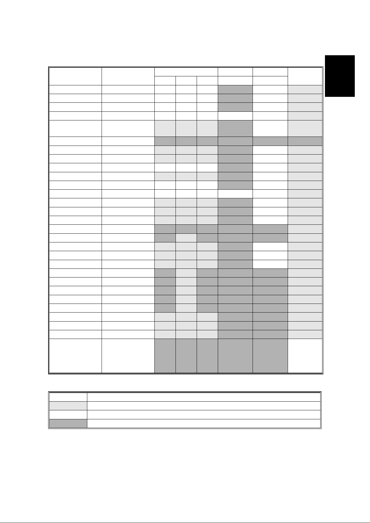
1.1.2 SUPPORTED PAPER SIZES
Paper Size (W x L)
Trays LCT Duplex
1st 2nd OP
By-pass/
Tray 2
Ledger 11 x 17” Y Y Y NYY
Legal 8.5 x 14“ Y Y Y NYY
Letter SEF 8.5 x 11” Y Y Y NYY
Letter LEF 11 x 8.5” Y Y Y Y Y Y
Half Letter
SEF
5.5 x 8.5”
#
Y
#
Y
#
Y
N N Y
Half Letter LEF 8.5 x 5.5” N N N N N N
Executive SEF 7.25 x 10.5” Y
Executive LEF 10.5 x 7.25” Y
#
#
#
Y
#
Y
#
Y
#
Y
NYY
N Y Y
A3 297 x 420 mm Y YY N Y Y
B4 257 x 364 mm Y
#
#
Y
#
Y
N Y Y
A4 SEF 210 x 297 mm Y Y Y NYY
A4 LEF 297 x 210 mm Y Y Y Y Y Y
B5 SEF 182 x 257 mm Y
B5 LEF 257 x 182 mm Y
A5 SEF 148 x 210 mm Y
#
#
#
#
Y
#
Y
#
Y
#
Y
#
Y
#
Y
NYY
NYY
NYY
A5 LEF 210 x 148 mm N N N N N Y
A6 SEF 105 x 148 mm N Y
Folio 8.25 x 13” Y
Foolscap 8.5 x 13” Y
F8 x 13”Y
#
#
#
Com10 Env. 4.125 x 9.5” N Y
Monarch Env. 3.875 x 7.5” N Y
C6 Env. 114 x 162 mm N Y
C5 Env. 162 x 229 mm N Y
DL Env. 110 x 220 mm N Y
8K 267 x 390 mm Y
16K SEF 195 x 267 mm Y
16K LEF 267 x 195 mm Y
#
#
#
#
N N N Y
#
Y
#
Y
#
Y
#
#
#
#
#
#
Y
#
Y
#
Y
#
Y
#
Y
#
Y
NYY
N Y Y
N Y Y
N N N Y
N N N Y
N N N Y
N N N Y
N N N Y
#
Y
#
Y
#
Y
N N Y
N N Y
N N Y
Custom [Minimum]
90 x 148 mm
[Maximum]
N N N N N Y
297 x 432 mm
#
#
#
#
#
#
#
#
#
#
#
#
#
#
#
#
#
#
#
#
#
#
#
#
#
#
#
C
Overall
Information
Remarks:
Y Supported. The paper size sensor detects the paper size.
#
Y
C
Y
N Not supported.
Supported. The user has to select the correct paper size for the tray.
Supported. The user has to enter the width and length of the paper.
1-3
Page 18

SOFTWARE ACCESSORIES 1 October, 1999
1.2 SOFTWARE ACCESSORIES
The printer drivers and utility software are provided on one CD-ROM. An auto-run
installer allows you to select which components to install. The service tools are not
provided on the CD-ROM.
1.2.1 PRINTER DRIVERS
Printer Language Windows 3.1x Windows 95/98 Windows NT4.0 Macintosh
PCL 6 Yes Yes Yes No
PCL 5e Yes Yes Yes No
PS3 Yes Yes Yes Yes
NOTE:
1) The printer drivers for Windows NT 4.0 are only for the Intel x86
platform. There is no Windows NT 4.0 printer driver for PowerPC, Alpha,
or MIPS platforms.
2) The PS3 drivers are all genuine AdobePS drivers. A PPD file for each
operating system is provided with the driver.
3) The PS3 drivers for Macintosh support Mac OS 7.1 or later versions.
4) The PS3 drivers for Windows 3.1x and Windows NT4.0 do not support
the “Proof Print” function.
1.2.2 UTILITY SOFTWARE
Software Description
Agfa Font Manager
(Win3.1x, 95/98, NT4)
Aficio Manager for Admin
(Win 95/98, NT4)
Aficio Manager for Client
(Win95/98, NT4)
Multi-Direct Print
(Win95/98, NT4)
Port Navi
(Win95/98, NT4)
A font management utility with screen fonts for the printer.
A printer management utility for network administrators. NI B
setup utilities are also available.
A printer management utility for client users.
A utility for peer-to-peer printing over a NetBEUI or TCP/IP
network.
A peer to peer print utility over a TCP/IP network. This
provides parallel printing and recovery printing function.
1.2.3 SERVICE TOOLS
Software Description
NBTFTP NIB firmware update utility for use on a NetBEUI network.
This utility is not on the Driver and Utilities CD-ROM; it is
issued separately as a service tool
1-4
Page 19
1 October, 1999 MACHINE CONFIGURATION
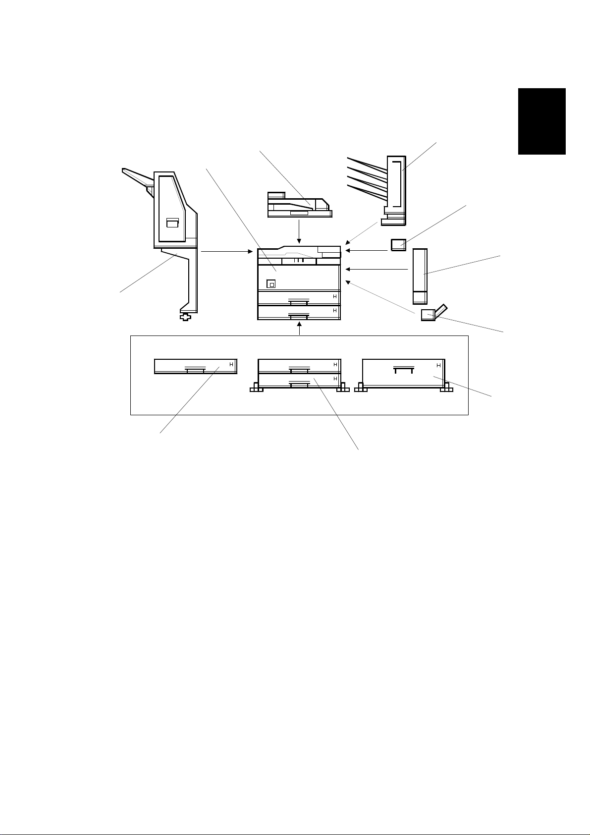
1.3 MACHINE CONFIGURATION
1.3.1 SYSTEM COMPONENTS
[A]
[J]
[I]
[B]
[C]
[H]
Overall
Information
[D]
[G]
[E]
G038V502.WMF
[F]
1-5
Page 20

MACHINE CONFIGURATION 1 October, 1999
Item
Main Unit G038 I
Option
Paper Tray Unit - 1 tray A861
Paper Tray Unit - 2 trays A860
LCT A862
By-pass Tray A899
Interchange Unit G531 B
Duplex Unit G529 C (See note 2, 3)
4-bin Mailbox G518 A (See note 2)
Bridge Unit A897 I
1000-sheet Finisher A681 H Used in common with
Internal Option
HDD G690
Memory 32or 64 MB G688 Used in common with
Others
Maintenance Kit G719
Machine
Code
No. Remarks
User installable
Used in common with
G
F
E
D
Stinger-C (See note 1)
User installable
Used in common with
Stinger-C/Russian-C
(See note 1)
User installable
Used in common with
Russian-C (See note 1)
User installable
Used in common with
Russian-C
User installable
User installable
User installable
User installable
Used in common with
Russian-C
(See note 4)
Service installation
Russian-C/NAD
(See note 4)
Service installation
Used in common with
Stinger-C/Russian-C
Service installation
Stinger-C/Russian-C
User installable
NOTE:
1) Only one of these options can be installed on the machine.
2) Requires the Interchange unit to be installed.
3) Requires the memory option to be installed.
4) The Bridge unit must be installed together with the 1000 sheet Finisher.
Either the LCT or Paper Tray Unit (2 trays) must also be installed.
1-6
Page 21

1 October, 1999 PAPER PATH
1.4 PAPER PATH
[F]
[A]
[B]
[E]
[C]
Overall
Information
[A]: Optional interchange unit
[B]: Optional duplex unit
[C]: Optional by-pass tray
[D]: Optional paper tray unit (2 trays)
[E]: Optional 1000-sheet finisher
[F]: Optional bridge unit
[D]
G038V101.WMF
1-7
Page 22

MECHANICAL COMPONENT LAYOUT 1 October, 1999
1.5 MECHANICAL COMPONENT LAYOUT
17
16
15
18
1
2
3
4
5
6
7
8
9
10
11
12
1. Exit roller
2. Hot roller
3. Fusing pressure roller
4. Cleaning unit
5. Drum
6. Transfer roller
7. Development roller
8. ID sensor
9. Registration roller
13
G038V503.WMF
14
10. Friction pad
11. Paper feed roller
12. Paper size sensor
13. Special paper sensor
14. Bottom plate
15. Polygon mirror motor
16. Laser unit
17. Toner supply bottle holder
18. Charge roller
1-8
Page 23

1 October, 1999 ELECTRICAL COMPONENT DESCRIPTIONS
1.6 ELECTRICAL COMPONENT DESCRIPTIONS
Refer to the electrical component layout on the reverse side of the point-to-point
diagram for the location of the components.
Symbol Name Function
Motors
M1 Polygonal Mirror Turns the polygonal mirror.
M2 Main Motor Drives the main unit components.
M3 Exhaust Fan Removes heat from around the fusing unit.
M4 Upper Paper Lift Raises the bottom plate in the 1st paper tray.
M5 Lower Paper Lift Raises t he bottom plate in the 2nd paper tray.
M6 Toner Supply
Magnetic Clutches
MC1 Upper Paper Feed Starts paper feed from the 1st paper tray.
MC2 Lower Paper Feed Starts paper feed from the 2nd paper tray.
MC3 Upper Paper Transport Drives the upper transport rollers.
MC4 Lower Paper Transport Drives the lower transport rollers.
MC5 Registration Drives the registration rollers.
Switches
SW1 M ain Switc h
SW2 Right Upper Cover Detects whether right upper cover is open or not.
SW3 Right Cover
SW4 Right Lower Cover Det ect s whether right lower cover is open or not.
SW5 Upper Paper Size
SW6 Lower Paper Size
SW7 Special Paper
SW8 New PCU Detect Det e ct s when a new PCU is installed.
SW9 Front Cover Safety
Sensors
S1 Toner Density (TD)
S2 1st Paper End
S3 1st Paper End
S4 Image Density (ID)
S5 Paper Overflow Detects paper overflow condition.
S6 Paper Exit Detects misfeeds.
S7 Upper Relay Detects misfeeds.
Rotates the toner bottle to supply toner to the
development unit.
Provides power to the machine. If this is off,
there is no power supplied to the machine.
Cuts the +5VLD and +24V dc power line and
detects whether the right cover is open or not.
Determines what size of paper is in the upper
paper tray.
Determines what size of paper is in the Lower
paper tray.
Determines the special paper is in the lower
paper tray.
Cuts the +5VLD and +24V dc power line and
detects whether the front cover is open or not.
Detects the amount of toner inside the
development unit.
Informs the CPU when the 1st paper tray runs
out of paper.
Informs the CPU when the 2nd paper tray runs
out of paper.
Detects the density of various patterns and the
reflectivity of the drum for process control.
Overall
Information
1-9
Page 24

ELECTRICAL COMPONENT DESCRIPTIONS 1 October, 1999
Symbol Name Function
S8 Lower Relay Detects misfeeds.
S9 Registration
S10 1st Paper Lift
S11 2nd Paper Lift
S12 1st Paper Height - 1
S13 1st Paper Height - 2
S14 2nd Paper Height - 1
S150 2nd Paper Height - 2
Detects misfeeds and controls registration clutch
off-on timin g.
Detects when the paper in the 1st paper tray is at
the feed height.
Detects when the paper in the 2nd paper tray is
at the feed height.
Detects the amount of paper in the 1st paper
tray.
Detects the amount of paper in the 1st paper
tray.
Detects the amount of paper in the 2nd paper
tray.
Detects the amount of paper in the 2nd paper
tray.
PCBs
PCB1 Engine Board Controls all printer engine functions.
PCB2 Printer Controller Board Controls the printer functions
PCB3 Network Interface Board Net work interface board
PCB4 PSU (Power Supply Unit)
Provides dc power to the system and ac power to
the fusing lamp and heaters.
PCB5 LDD (Laser Diode Driver) Controls the laser diode.
PCB6 Operation Panel Controls the operation panel.
PCB7 High Voltage Supply
Supplies high voltage to the drum charge roller,
development roller, and transfer roller.
PCB8 Memory (Option) Expands memory capacity.
Lamps
L1 Fusing Lamp Heats the hot roller.
L2 Quenching Lamp
Neutralizes any charge remaining on the drum
surface after cleaning.
Others
TF1 Fusing Thermofu s e
Opens the fusing lamp circuit if the fusing unit
overheats.
TH1 Fusing Thermistor Det ects the temperature of the hot roller.
LSD 1
Laser Synchronization
Detector
Detects the laser beam at the start of the main
scan.
1-10
Page 25
1 October, 1999 PRINTING PROCESS
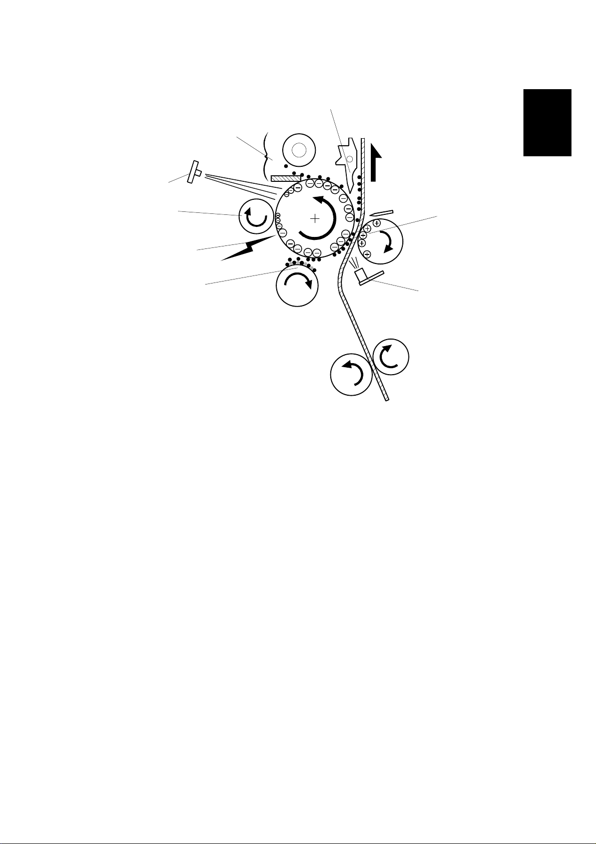
1.7 PRINTING PROCESS
[6]
Overview
[7]
[8]
Overall
Information
[1]
[5]
[2]
[3]
G038V504.WMF
[4]
1. DRUM CHARGE
The charge roller gives a negative charge to the organic photoconductive
(OPC) drum. The charge remains on the surface of the drum because the OPC
layer has a high electrical resistance in the dark.
2. LASER EXPOSURE
Processed data from the computer/network is retrieved from the memory and
transferred to the drum by a laser beam, which forms an electrical latent image
on the drum surface. The amount of charge remaining as a latent image on the
drum depends on the laser beam intensity, which is controlled by the engine
board.
3. DEVELOPMENT
The magnetic developer brush on the developm e nt rol ler s comes in contact
with the latent image on the drum surface. Toner particles are electrostatically
attached to the areas of the drum surface where the laser reduced the negative
charge on the drum.
4. ID SENSOR
The laser forms a sensor pattern on the drum surface. The ID sensor measures
the reflectivity of the pattern. The output signal is one of the factors used for
toner supply control. Also, the ID sensor measures the reflectivity of the drum
surface. The output signal is used for charge roller voltage control.
1-11
Page 26

PRINTING PROCESS 1 October, 1999
5. IMAGE TRANSFER
Paper is fed to the area between the drum surface and the transfer roller at the
proper time for aligning the print paper and the developed image on the drum
surface. Then, the transfer roller applies a high positive charge to the reverse
side of the paper. This positive charge pulls the toner particles from the drum
surface onto the paper. At the same time, the paper is electrostatically attracted
to the transfer roller.
6. PAPER SEPARATION
Paper separates from the drum as a result of the electrostatic attraction
between the paper and the transfer roller. The discharge plate helps separate
the paper from the drum.
7. CLEANING
The cleaning blade removes any toner remaining on the drum surface after the
image transfers to the paper.
8. QUENCHING
The light from the quenching lamp electrically neutralizes the charge on the
drum surface.
1-12
Page 27
1 October, 1999 BOARD STRUCTURE
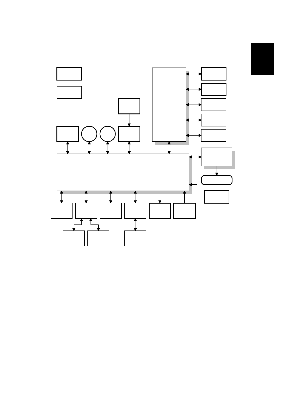
1.8 BOARD STRUCTURE
1.8.1 OVERVIEW
Standard
components
Operation
Panel
Overall
Information
Optional
components
Power
Pack
By-pass
Tray
Motors
Interchange
Unit
Polygon
Motor
Engine Board
Paper Tray
or
LCT
Laser
Synch.
LDDR
Bridge
Unit
Printer
Controller
Board
Clutches
Network
Interface
PS DIMM
DRAM DIMM
HDD
PSU
Fusing Lamp
Thermistor
Sensors
Duplex
Unit
4-bin
Mailbox
Finisher
G038V501.WMF
The engine control firmware controls the components connected to the engine
board. The printer control board controls the connected components.
1-13
Page 28

BOARD STRUCTURE 1 October, 1999
1.8.2 DESCRIPTIONS
1. Engine Board
The engine board controls the following functions:
•
Engine sequence
•
Machine control, printer engine control
•
Timing control for peripherals
•
Video control
•
Drive control for the sensors, motors, solenoids, and high voltage supply
board
2. Printer Control Board
The printer control board handles the following functions:
•
Interface of the connected components to the engine board
•
Printer host interface
•
Edge smoothing and toner saving
•
Operation panel interface
•
Interface and control of NIB and the other additional options (HDD, PS
DIMM, and DRAM DIMM)
3. LD Drive Board
This is the laser diode drive circuit board.
4. Network Interface Board (NIB)
The network interface board allows the printer to be used on a network
5. HDD Unit (Option)
The HDD unit stores the data to perform the following functions.
•
Additional soft fonts
•
Collation
•
Proof-print
•
Downloading forms for form overlay
6. PS DIMM
This is to add the PostScript feature.
7. DRAM DIMM (Option)
This is used for an additional printer processing memory area and for soft fonts.
8. Control Panel Board
Controls the display panel, the LED, and the touch keypad.
1-14
Page 29

1 October, 1999 LASER EXPOSURE
2. DETAILED SECTION DESCRIPTIONS
2.1 LASER EXPOSURE
2.1.1 OVERVIEW
[H]
[A]
[I]
[C]
[D]
[B]
[F]
[G]
The LD unit [A] outputs a laser beam to the polygon mirror [B] through the
cylindrical lens [C]. The shield glass [D] prevents dust from reaching the polygon
mirror.
[E]
G038D523.WMF
Detailed
Descriptions
Each surface of the polygon mirror reflects one full main scan line. The laser beam
goes to the F-theta mirror [E], mirror [F], and BTL (barrel toroidal lens) [G]. Then
the laser beam goes to the drum through the toner shield glass [H].
The laser synchronizing detector [I] determines the starting position for the main
scan.
The speed of the polygon mirror motor is 28,818.9 rpm for 600 dpi.
2-1
Page 30
LASER EXPOSURE 1 October, 1999
2.1.2 AUTO POWER CONTROL (APC)
LD LEVEL
LD ON
LD OFF
LD OFF
VIDEO
LD
Controller
LD Drive Board
VIDEO
LD Driver
LD
VREF
Reference
Circuit
+5V
PD LD
Monitor
G038D510.WMF
The LD driver IC drives the laser diode. To prevent the intensity of the laser beam
from changing because of the temperature, the machine monitors the current
passing through the laser diode (LD). The machine adjusts the current to the laser
diode by comparing it with the reference level from the reference circuit.
This auto power control is done just after the machine is turned on and during
printing while the laser diode is active.
The laser diode power is adjusted on the production line.
NOTE:
Do not touch the variable resistors on the LD unit in the field.
2-2
Page 31

1 October, 1999 LASER EXPOSURE
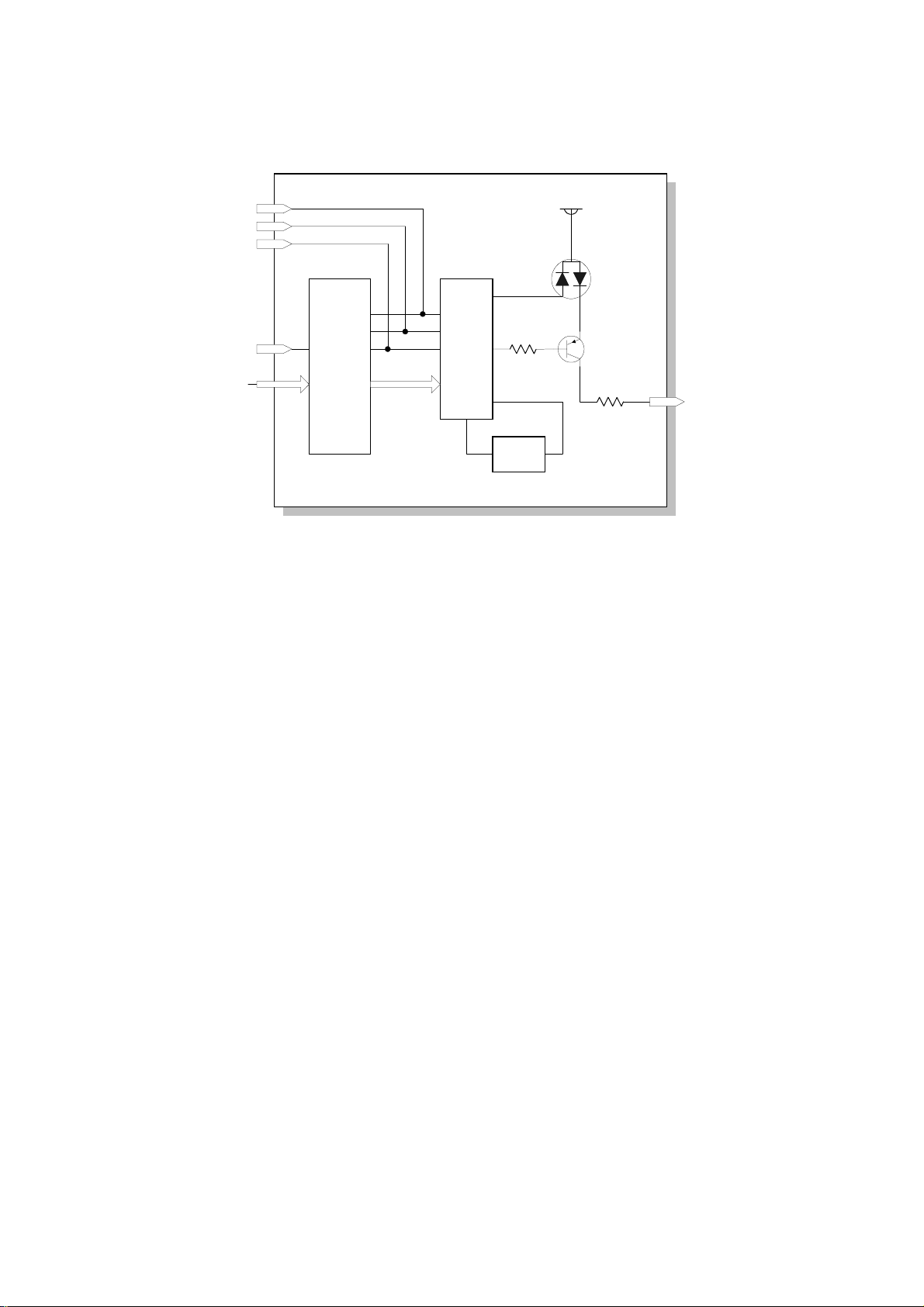
2.1.3 LD SAFETY SWITCH
Interlock
SW
LD Drive Board
PSU
+5VLD +5VLD
Engine
Board
To ensure technician and user safety and to prevent the laser beam from
inadvertently switching on during servicing, safety switches are located at the front
cover and right cover. The switches are installed on the +5VLD line coming from
the power supply unit through the Engine control board.
LDD:
VCC
LD Control IC
PD
LD
Laser
Beam
Optical Path
OPC
Drum
G038D501.WMF
Detailed
Descriptions
When the front cover or the right cover is opened, the power supply to the laser
diode is interrupted.
2-3
Page 32

PHOTOCONDUCTOR UNIT (PCU) 1 October, 1999
2.2 PHOTOCONDUCTOR UNIT (PCU)
2.2.1 OVERVIEW
10
9
8
1
7
6
2
G038D201.WMF
3
4
11
5
The PCU consists of the components shown in the above illustration. An organic
photoconductor (OPC) drum (diameter: 30 mm) is used in this machine.
1. Cleaning Blade
2. Toner Collection Coil
3. Pick-off Pawl
4. OPC Drum
5. ID Sensor (see note)
NOTE:
The machine informs the user when the PCU life has finished. However, the user
can continue to make copies.
This warning message can be disabled by the printer engine service mode (Service
Menu 2: Change PM Mes).
These parts are not included in the PCU.
6. Development Roller
7. Development Unit
8. Charge Roller
9. Charge Roller Cleaning Pad
10. Quenching Lamp (see note)
11. Transfer Roller (see note)
2-4
Page 33

1 October, 1999 PHOTOCONDUCTOR UNIT (PCU)
2.2.2 DRIVE MECHANISM
[A]
[E]
[B]
[C]
[D]
G038D202.WMF
The main motor [A] drives the drum [B] through a series of gears, a timing belt [C],
and the drum drive shaft [D]. The main motor assembly includes a drive controller,
which outputs a motor lock signal when the rotation speed is out of the specified
range.
Detailed
Descriptions
The fly-wheel [E] on the end of the drum drive shaft stabilizes the rotation speed
(this prevents banding and jitter from appearing on printouts).
2-5
Page 34

PHOTOCONDUCTOR UNIT (PCU) 1 October, 1999
2.2.3 NEW PCU DETECTION MECHANINSM
[A]
G038D206.WMF
[B]
[C]
When the PCU counter reaches 60K, the “Replace PCU” message is displayed.
The new PCU detect switch [A] detects when a new PCU is installed. Each PCU
has an actuator [B]. When a new PCU is installed in the machine, the actuator [B]
pushes the new PCU detect switch. The actuator is a sector gear, and this gear
engages with the drum gear [C]. When the drum rotates, the actuator is released
from the drum gear. The actuator drops away from the new PCU detect switch and
remains in this "down" position for the duration of the PCU's life.
The machine can recognize when a new PCU has been installed in the machine
because the actuator of the new PCU comes in contact with the new PCU detect
switch. Then, the machine automatically resets the PCU counter.
After the front cover and right cover are closed, the machine then performs the TD
sensor initial setting procedure automatically (for about 45 seconds). During this
time, the drum rotates and the actuator drops away from the sensor.
While the machine performs the TD sensor initial setting, the machine makes an ID
sensor pattern on the drum. This checks whether the developer has fallen into the
development unit (in other words, it checks whether the user or technician
remembered to remove the developer seal from the PCU at machine installation). If
the machine does not detect the ID sensor pattern, SC 392 is generated.
NOTE:
The PCU counter can be cleared by the printer engine service mode
(Service Menu 2: PCU Count clr).
2-6
Page 35

1 October, 1999 DRUM CHARGE
2.3 DRUM CHARGE
2.3.1 OVERVIEW
[D]
[C]
[A]
[B]
G038D203.WMF
This machine uses a drum charge roller to charge the drum. The drum charge
roller [A] always contacts the surface of the drum [B] to give it a negative charge of
-900V.
Detailed
Descriptions
The high voltage supply board gives a negative dc voltage to the drum charge
roller through the spring [C] and terminal plate [D].
2-7
Page 36

DRUM CHARGE 1 October, 1999
2.3.1 CHARGE ROLLER VOLTAGE CORRECTION
Correction for Environmental Conditions
[A]
28.9 cm
+
2 cm
[B]
ID Sensor Pattern
Charge Voltage
Laser Diode
Drum Potential
Development Bias
ID Sensor Output
On
Off
2 cm
Sub Scan Direction
-1650 V
-1450 V
-900 V
-700 V
-600 V
-400 V
-150 V
V sg (4.00 V)
V sdp (3.70 V)
V sp (0.50 V)
t
G038D516.WMF
With a drum charge roller system, the voltage transferred from roller to drum varies
with the temperature and humidity around the drum charge roller. The lower the
temperature or humidity is, the higher the applied voltage required.
To compensate, the machine uses the ID sensor to measure the effects of current
environmental conditions. For this measurement, the process control parameters
are balanced so that any small change in drum potential caused by environmental
effects is reflected in a change in the amount of toner transferred to the drum.
This measurement is made immediately after the ID sensor pattern for toner
density control. Immediately after making ID sensor pattern [A], the charge roller
voltage stays on, but the development bias goes up to -600V; as a result the drum
potential is reduced to -700V. The laser diode is not switched on, and the drum
potential is now slightly higher than the development bias, so only a very small
amount of toner transfers to the drum. The ID sensor measures the density of this
pattern [B], and the output voltage is known as Vsdp. This voltage is compared with
Vsg (read from the bare drum at the same time).
2-8
Page 37

1 October, 1999 DRUM CHARGE
If the humidity drops, the drum potential goes up (to a higher –ve voltage) even if
the charge roller voltage supply stays the same (efficiency of voltage transfer is
higher with lower humidity). As a result, less toner is transferred to ID sensor
pattern [B]. If the sensor output reaches a certain point, the drum charge voltage
will be reduced.
To determine whether to change the drum charge roller voltage, the machine
compares Vsdp with Vsg.
•
Vsdp / Vsg > 0.95 = Reduce the magnitude of the drum charge voltage by 50 V
•
Vsdp / Vsg < 0.90 = Increase the magnitude of the drum charge voltage by 50 V
2.3.2 ID SENSOR PATTERN PRODUCTION TIMING
An ID sensor pattern is made in the following conditions.
•
During warming up at power on
•
If the machine starts warming up after entering the energy saver mode
Detailed
Descriptions
2-9
Page 38

DRUM CHARGE 1 October, 1999
2.3.3 DRUM CHARGE ROLLER CLEANING
[C]
[D]
[B]
[A]
G038D205.WMF
Because the drum charge roller [A] always contacts the drum, it gets dirty easily.
So, the cleaning pad [B] also contacts the drum charge roller all the time to clean
the surface of the drum charge roller.
The pin [C] at the rear of the cleaning pad holder touches the cam gear [D], and
this gear moves the cleaning pad from side to side. This movement improves the
cleaning.
2-10
Page 39

1 October, 1999 DEVELOPMENT
2.4 DEVELOPMENT
2.4.1 OVERVIEW
5
4
G038D301.WMF
3
2
The development unit consists of the following parts.
1. Development roller
2. Mixing auger 2
4. Mixing auger 1
5. Doctor blade
3. TD sensor
Detailed
Descriptions
1
This machine uses a single-roller development system. Two mixing augers mix the
developer. The toner density (TD) sensor and image density (ID) sensor (see the
illustration in the PCU section) are used to control toner density.
2-11
Page 40

DEVELOPMENT 1 October, 1999
2.4.2 DRIVE MECHANISM
[A]
[B]
[D]
[C]
G038D304.WMF
The main motor [A] drives the development roller [B] and mixing augers [C] through
a train of gears and the development drive shaft [D]. When the PCU is pushed in,
the development drive shaft engages the development roller gear.
The development drive gears (except for the gears in the development unit) are
helical gears. These gears are quieter than normal gears.
2-12
Page 41

1 October, 1999 DEVELOPMENT
2.4.3 DEVELOPER MIXING
[D]
[C]
[A]
[B]
[B]
[A]
G038D302.WMF
This machine uses 2 mixing augers, [A] and [B], to keep the developer evenly
mixed. Mixing auger 2 [A] transports excess developer, scraped off the
development roller [C] by the doctor blade [D], towards the front of the machine.
Mixing auger 1 [B] returns the excess developer, along with new toner, to the rear
of the mixing assembly. Here the developer is reapplied to the development roller.
Detailed
Descriptions
2-13
Page 42

DEVELOPMENT 1 October, 1999
2.4.4 DEVELOPMENT BIAS
[B]
[A]
G038D303.WMF
This machine uses a negative-positive development system, in which black areas
of the latent image are at a low negative charge (about -150 ± 50 V) and white
areas are at a high negative charge (about -900 V).
To attract negatively charged toner to the black areas of the latent image on the
drum, the high voltage supply board applies a bias of -600 volts to the development
rollers throughout the image development process. The bias is applied to the
development roller shaft [A] through the drive shaft [B].
The development bias voltage (-600 V) can be adjusted with the printer service
mode (Service Menu 2: Developer bias).
2-14
Page 43

1 October, 1999 DEVELOPMENT
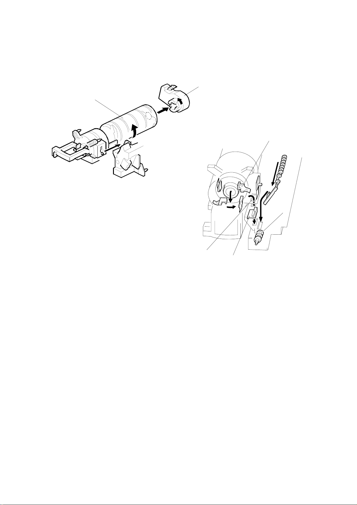
2.4.5 TONER SUPPLY
Toner bottle replenishment mechanism
[E]
[G]
[A]
[F]
Detailed
Descriptions
[H]
[D]
[C]
G038D507.WMF
[B]
When a toner bottle is placed in the bottle holder unit [A] and the unit is pushed in
completely, pin [B] moves against the side [C] of the PCU, and the toner shutter [D]
is pulled out to open the bottle. When the toner bottle holder lever [E] is put back in
the original position, the cap [F] on the toner bottle is pulled away and kept in place
by the chuck [G].
The toner supply mechanism transports toner from the bottle to the development
unit. The toner bottle has a spiral groove [H] that helps move toner to the
development unit.
When the bottle holder unit is pulled out to add a new toner bottle, the following
happens automatically to prevent toner from scattering.
•
The chuck releases the toner bottle cap into its proper position.
•
The toner shutter shuts to block the opening as a result of pressure from a
spring.
2-15
Page 44
DEVELOPMENT 1 October, 1999
Toner supply mechanism
[A]
[B]
[C]
G038D508.WMF
[D]
[E]
G038D306.WMF
The toner supply motor [A] drives the toner bottle [B] and the mylar blades [C].
First, the toner falls down into the toner bottle holder. The toner supply mylar
blades transfer the toner to the slit [D]. When the PCU is installed in the machine,
the shutter [E] above the PCU is opened by the machine frame. Then the toner
falls down into the development unit through the slit and the shutter.
2-16
Page 45

1 October, 1999 DEVELOPMENT
2.4.6 TONER DENSITY CONTROL
Overview
There are four modes for controlling toner supply as shown in the following tables.
The mode can be changed with by the printer service mode (Service Menu 2:
Toner supply). The factory setting is P+T control mode.
Basically, toner density is controlled using the standard TD sensor voltage (Vts),
toner supply reference voltage (Vref), actual TD sensor output voltage (Vt), and ID
sensor output data (Vsp/Vsg).
Cross-reference:
Section 4.2 Service Program Mode
Toner Supply Clutch On Time
Calculation
TD Sensor Output
(Vt)
Detailed
Descriptions
Vt Reference
Voltage (Vref)
New Vref
Vt Reference
Voltage Update
Vref Update
ID Sensor Output
(Vsp/Vsg)
TD Sensor Initial
Setting (Vts)
G038D517.WMF
2-17
Page 46

DEVELOPMENT 1 October, 1999
There are four toner density control modes:
Mode P+T Control (Normally use this setting only)
Toner supply decision Compare Vt with a reference voltage (Vts or Vref)
Toner control process
Toner is supplied to the development unit when Vt is higher
than the reference voltage (Vts or Vref). This mode keeps the
Vref value for use the next toner density control.
Vts is used for the first toner density control after a new PCU
has been installed, until it has been corrected with the ID
sensor output.
Vref is used after Vts has been corrected with the ID sensor
output voltage (corrected during the first toner density control
for a new PCU).
2-18
Page 47

1 October, 1999 DEVELOPMENT
Toner density sensor initial setting
The TD sensor initial setting procedure is performed automatically when the new
PCU is installed in the machine. During TD sensor initial setting, the TD sensor is
set to the TD sensor output to the value programmed in the printer service mode
(T sensor set: default: 2.3V). This value will be u s ed as the standard reference
voltage (Vts) of the TD sensor.
Toner density measurement
Toner density in the developer is detected once every print cycle. The sensor
output voltage (Vt) during the detection cycle is compare with the standard
reference voltage (Vts) or the toner reference voltage (Vref).
Vsp/Vsg detection
The ID sensor detects the following voltages.
•
Vsg: The ID sensor output when checking the drum surface
•
Vsp: The ID sensor output when checking the ID sensor pattern
In this way, the reflectivity of both the drum surface and the pattern on the drum are
checked. This compensates for any variations in the reflectivity of the pattern on
the drum or the reflectivity of the drum surface.
The ID sensor pattern is made on the drum by charge roller and laser diode.
Vsg/Vsp is not detected every page or job; it is detected at the following times to
decide Vref.
•
During warming up at power on
•
If the machine starts warming up after a certain time has passed since
entering the energy saver mode.
Detailed
Descriptions
Toner supply reference voltage (Vref) determination
The toner supply reference voltage (Vref) is the threshold voltage for the toner
supply determination. Vref is determined using the following data,
•
ID sensor output (Vsp/Vsg)
•
(Vts or the current Vref) - Vt
Toner supply determination
The reference voltage (Vts or Vref) is the threshold voltage for determining whether
or not to supply toner. If Vt becomes greater than the reference voltage, the
machine supplies additional toner.
2-19
Page 48

DEVELOPMENT 1 October, 1999
Toner Supply Motor On Time Determinations
For sensor control modes 1 and 2, the toner supply motor on time is decided by the
following factors.
•
Vt
•
Vref
•
TD sensor sensitivity (coefficient: S, value is 0.4)
There are seven levels for toner supply motor on time as shown below.
Level Decision M ot or On Time (seconds)
1
2
3
4
5
6
7
Vref < Vt ≤ S/16
Vref < Vt ≤ S/8
Vref < Vt ≤ S/4
Vref < Vt ≤ S/2
Vref < Vt ≤ 4S/5
Vt ≥ 4S/16
Vt ≥ Vref+S
(30); see note 3
(30); see note 3
0.6
1.2
2.4
4.8
9.6
NOTE:
1) (30) means that toner is supplied intermittently in a 1/3 duty cycle (1 s
on, 2 s off) for 30 seconds
2-20
Page 49

1 October, 1999 DEVELOPMENT
2.4.7 TONER NEAR END/END DETECTION AND RECOVERY
The toner near end and end conditions are detected using the Vt and Vref values,
in a similar way to toner density control.
This is done in all toner supply modes except for fixed quantity 2, when toner end is
not detected.
Toner Near End Detection
If Vt is at level 6 (see the table on the previous page) five times consecutively, the
machine enters the toner near end condition and the toner end indicator starts
blinking. Then the machine supplies toner for a certain time in accordance with the
table explained in the previous section.
Toner Near End Recovery
If the machine detects “Vt < (Vref or Vts) + 4S/5” twice consecutively when in one
of the following situations, the machine leaves the toner near end condition.
•
While in the toner recovery cycle (supplying toner on and off for 30 s - see
the previous page) after the machine has detected a toner near end
condition.
•
During printing in the toner near end condition.
•
If the front cover is opened and closed for more than 10 seconds while a
toner near end condition exists.
Detailed
Descriptions
Toner End Detection
There are two situations for entering the toner end condition.
•
When Vt is level 7 th ree times consecutively, the machine enters the toner
end condition.
•
When “Vt+S > Vt > (Vref or Vts) + 4S/5” is detected in the toner near end
condition, then 50 prints can be made after this condition.
Toner End Recovery
If the front cover is opened and closed for 10 seconds while a toner end condition
exists and the toner bottle is replaced, the machine attempts to recover using the
same procedure as for toner near end/end detection.
2-21
Page 50

DRUM CLEANING AND TONER RECYCLING 1 October, 1999
2.5 DRUM CLEANING AND TONER RECYCLING
2.5.1 DRUM CLEANING
[A]
[B]
G038D201.WMF
The cleaning blade [A] removes any toner remaining on the drum after the image is
transferred to the paper. This model uses a counter blade system.
The cleaning blade scrapes off toner remaining on the drum. When toner builds up
in the cleaning unit, toner at the top of the pile is removed by the toner collection
coil [B].
To remove the toner and other particles that are accumulated at the edge of the
cleaning blade, the drum turns in reverse for about 5 mm at the end of every print
job.
2-22
Page 51

1 October, 1999 DRUM CLEANING AND TONER RECYCLING
2.5.2 TONER RECYCLING
[A]
[A]
Detailed
Descriptions
G038D205.WMF
[B]
[B]
G038D306.WMF
[C]
Toner picked up by the toner collection coil [A], is transported to the opening [B] at
the side of the PCU. Then, this toner falls into the development unit with new toner
coming from the toner bottle and it is all mixed together by mixing auger 1 [C] and
used again.
2-23
Page 52

PAPER FEED 1 October, 1999
2.6 PAPER FEED
2.6.1 OVERVIEW
1 2 3 4 5
6
7
8
9
G038D701.WMF
12
There are two paper trays, each of which can hold 500 sheets.
The paper tray feed stations use a friction pad system.
The two relay sensors are used for paper jam detection.
The components of the paper feed station are as follows.
1. Paper Lift Sensor
2. Paper Height -1 Sensor
3. Paper Height -2 Sensor
4. Paper End Sensor
5. Paper Feed Roller
6. Paper Size Sensor
7. Upper Relay Sensor
8. Upper Relay Roller
9. Lower Relay Roller
10. Special Paper Sensor
11. Lower Relay Sensor
12. Friction Pad
10
11
2-24
Page 53

1 October, 1999 PAPER FEED
2.6.2 PAPER FEED DRIVE MECHANISM
[A]
[D]
[B]
[C]
Detailed
Descriptions
G038D702.WMF
The main motor [A] drives the pick-up and feed mechanism of both the first and
second paper trays. The paper feed clutches [B] transfer drive from this motor to
the paper feed rollers [C].
When the paper feed clutch turns on, the feed rollers s tart to feed the paper. The
paper feed clutch stays on until shortly after the registration sensor [D] has been
activated.
2-25
Page 54

PAPER FEED 1 October, 1999
2.6.3 PAPER FEED AND SEPARATION MECHANISM
[A]
[B]
[C]
A860D104.WMF
The paper feed roller [A] drives the top sheet of paper from the paper tray. The
friction pad [B] allows only one sheet to feed at a time. The friction pad applies
pressure to the feed roller with a spring [C].
The friction pad pressure cannot be adjusted.
2-26
Page 55

1 October, 1999 PAPER FEED
2.6.4 PAPER LIFT MECHANISM
[B]
[A]
[D]
[C]
Detailed
Descriptions
[G]
[F]
G038D521.WMF
[K]
[H]
[A]
[E]
[B]
[I]
[J]
[C]
[D]
[E]
G038D522.WMF
The paper size switch detects when the tray is pushed in.
When the paper tray is pushed into the machine, the pin [A] for the lift motor
pressure shaft engages the lift motor coupling [B] and the pin [C] for the bottom
plate lift shaft in the tray engages the bottom plate pressure lever coupling [D]. The
pin [E] on the rear of the tray pushes the lock lever so that the lift motor can lift the
bottom plate pressure lev er .
The lift motor turns on, and turns clockwise as viewed on the diagram. The main
pressure spring [K] pulls the bottom plate pressure lever, and this lifts the tray
bottom plate.
When the top of the stack touches the feed roller, the motor cannot pull up the
plate any more, so it pulls the actuator [G] into the lift sensor [F]. Then the lift motor
reverses a certain time (200 ms or 600 ms), depending on the paper size, to
reduce this pressure. For smaller paper, it reverses the larger amount (600 ms) to
reduce the pressure more.
2-27
Page 56

PAPER FEED 1 October, 1999
For A4-width paper or wider, a projection [H] on the side fence engages the
secondary pressure spring [J] through a lever [I]. Then, the secondary pressure
spring [J] applies paper feed pressure in addition to the main pressure spring [K], to
ensure that extra pressure is applied to wider paper.
When the paper tray is pulled ou t, the pins [A, C] disengage from the couplings [B,
D], and the bottom plate drops. To make it easier to push the tray in, the lift motor
rotates backwards 1.7 seconds to return the bottom plate pressure lever coupling
[D] to the original position.
2.6.5 PAPER END DETECTION
[A]
[B]
[C]
G038D520.WMF
If there is some paper in the paper tray, the paper stack raises the paper end feeler
[A] and the paper end sensor [B] is deactivated.
When the paper tray runs out of paper, the paper end feeler drops into the cutout
[C] in the tray bottom plate and the paper end sensor is activated.
When the paper tray is drawn out with no paper in the tray, the shape of the paper
end feeler causes it to lift up.
2-28
Page 57

1 October, 1999 PAPER FEED
2.6.6 PAPER HEIGHT DETECTION
[B]
[A]
[C]
[C]
Detailed
Descriptions
G038D522.WMF
The amount of paper in the tray is detected by the combination of on/off signals
from two paper height sensors [A] and [B].
When the amount of paper decreases , the bottom plate pressure lever [C] moves
the actuator up.
The following combination of sensor signals is sent.
Amount of Paper Paper Height Sensor 1 Paper Height Sensor 2
Near End OFF ON
30% ON ON
70% ON OFF
100% OFF OFF
When the tray contain s paper of a small width, the paper feed pressure may
become too low when the thickness of the remaining stack of paper has
decreased. The lift motor rotates forward 400 ms after the sensor detects a certain
amount of paper remaining in the tray to increase paper feed pressure, simulating
the pressure generated by a full tray.
2-29
Page 58

PAPER FEED 1 October, 1999
2.6.7 PAPER SIZE DETECTION
SW
Size
A3
A4 LEF
A4 SEF
A5 SEF,
1/2
8
" x 14"
B4, 11" x 17"
B5 LEF,
1/2
11" x 8
B5 SEF,
1/2
8
* (Asterisk) ---
"
" x 11”
--- --- ---
--- ---
---
9999
: ON (Not pushed)
---: OFF (Pushed)
1234
---
99999
9
99
99999
9
99
9999
---
9999
--- --- ---
99999
9999
9999
---
--- ---
99999
9
99
9999
---
99
9
99
99
---
9999
[B]
[A]
G038D533.WMF
There are four paper size microswitches [A] on the front right plate of the paper tray
unit. The switches are actuated by a paper size actuator [B] behind the paper size
indicator plate, which is on the front right of the tray.
Each paper size has its own actuator, with a unique combination of notches. To
determine which size has been installed, the CPU reads which microswitches the
actuator has switched off.
The CPU disables paper feed from a tray if the paper size cannot be detected. If
the paper size actuator is broken, or if there is no tray installed, the Add Paper
indicator will light.
When the paper size actuator is at the “*” mark, the paper tray can be set up to
accommodate one of a wider range of paper sizes by using user tools. If the paper
size for this position is changed without changing the user tool setting, a paper jam
will result.
2-30
Page 59

1 October, 1999 PAPER FEED
2.6.8 SPECIAL PAPER SETTING
[B]
[A]
Detailed
Descriptions
G038D703.WMF
When feeding thick paper and envelopes, the user must use the 2nd paper tray (if
the optional by-pass table is not installed), and turn lever [A] to the right. Then,
when sliding the tray into the machine, the lever does not push the special paper
switch [B] (it stays off), and the machine detects that there is special paper in the
2nd paper tray.
When the machine detec ts the special paper signal , the fusing temperature and the
transfer roller current will be changed as follows.
1. Fusing temperature: Current operation temperature +10 °C
2. Transfer roller current:
A3 width (11"): 14 µA
B4 width (10"): 15 µA
A4 width (8.5"): 17 µA
A5 width (5.5"): 20 µA
Note that for the by-pass tray, the fusing and transfer conditions for special paper
are also applied if the user uses thick (non-standard) mode.
2-31
Page 60

PAPER FEED 1 October, 1999
2.6.9 SIDE AND END FENCES
[A]
[B]
A860D110.WMF
[D]
[C]
A860D109.WMF
Side Fences
If the tray is full of paper and it is pushed in strongly, the fences may deform or
bend. This may cause the paper to skew or the side-to-side registration to be
incorrect. To correct this, each side fence has a stopper [A] attached to it. Each
side fence can be secured with a screw [B], for customers who do not want to
change the paper size.
End Fence
As the amount of paper in the tray decreases, the bottom plate [C] lifts up
gradually. The end fence [D] is connected to the bottom plate. When the tray
bottom plate rises, the end fence moves forward and pushes the back of the paper
stack to keep it squared up.
2-32
Page 61

1 October, 1999 PAPER FEED
2.6.10 PAPER REGISTRATION
[A]
[B]
[C]
Detailed
Descriptions
[D]
G038D702.WMF
G038D704.WMF
The drive from the main motor [A] is transmitted to the registration roller through
the registration clutch gear [B].
The registration sensor [C] is used for correcting paper skew and for detecting
paper misfeeds.
The cleaning pad [D] contacts the registration roller. It removes paper dust from the
registration roller so that this dust will not transfer into the development unit through
the drum cleaning unit.
The amount of paper buckle at the registration roller to correct skew can be
adjusted with the printer service mode (Service Menu 2: Regist Sag).
Cross-reference:
Section 4.2 Service Program Mode
2-33
Page 62

IMAGE TRANSFER AND PAPER SEPARATION 1 October, 1999
2.7 IMAGE TRANSFER AND PAPER SEPARATION
2.7.1 OVERVIEW
[C]
[B]
G038D401.WMF
[A]
[C]
[A]
G038D403.WMF
[D]
G038D402.WMF
The machine uses a transfer roller [A], which touches the surface of the drum [B].
The high voltage supply board supplies a positive current to the transfer roller,
which attracts the toner from the drum onto the paper. The current depends on the
paper width, paper type, and paper feed tray.
The curvature of the drum and the antistatic plate [C] help the paper to separate
from the drum. The high voltage supply board also supplies a negative dc voltage
to the antistatic plate.
Drive from the drum through a gear [D] turns the transfer roller
The transfer current can be adjusted by the printer service mode (Service Menu 2:
Transfer set).
Cross-reference:
Section 4.2 Service Program Mode
2-34
Page 63

1 October, 1999 IMAGE TRANSFER AND PAPER SEPARATION
2.7.2 IMAGE TRANSFER MECHANISM
There are two transfer current levels: low transfer current level and high transfer
current level. The image transfer procedure is as follows:
1. When the CPU receives the image writing start signal, the CPU instructs the
high voltage supply board to supply +10µA (low transfer current level) to the
roller. This prevents any positively charged toner on the drum surface from
transferring to the transfer roller.
2. At a certain time after the low transfer current has been supplied to the roller,
+13µA (paper fed from the paper tray) is applied to the roller to transfer the
toner to the paper.
3. After the trailing edge of the paper has passed through the roller, transfer
current turns off. In multiple printing, the transfer current shifts again to the low
transfer current.
The default transfer roller current (high transfer current level) is as shown in the
following table. The transfer current can be adjusted using the printer service
mode, except for the low transfer current.
By-pass Tray /
Paper Size Paper Tray Duplex
A3/11" x 17",
A4/8
B4
A4/11" x 8
A5/5
A5/8
x 11" SEF
1/2
1/2
x 8
1/2
1/2
x 5
1/2
1/2
LEF,
SEF
LEF
13 µA 10 µA 14 µA
13 µA 12 µA 15 µA
13 µA 16 µA 17 µA
15 µA 16 µA 20 µA
2nd Paper Tray
(Special Paper)
Detailed
Descriptions
Be careful when increasing the transfer current. This might cause a ghosting effect,
in which part of the image at the top of the page is repeated lower down the page
at a lower density. It may also damage the OPC drum in the worst case.
2-35
Page 64

IMAGE TRANSFER AND PAPER SEPARATION 1 October, 1999
2.7.3 TRANSFER ROLLER CLEANING
If the paper size is smaller than the image, or if a paper jam occurs during printing,
toner may be transferred to the roller surface. To prevent the toner from
transferring to the back side of the printouts, the transfer roller requires cleaning
before the next printing run.
During transfer roller cleaning, the high voltage supply unit supplies a negative
cleaning current (-4 µA) to the transfer roller. Any negatively charged toner on the
transfer roller is then transferred back to the drum. Then a positive cleaning current
(+10 µA) is applied to the transfer roller to push back to the drum any positively
charged toner on the transfer roller.
The machine goes through the cleaning mode in the following conditions:
•
Before starting the printing job
•
Just after the power is switched on.
•
After a jam has been cleared
2.7.4 PAPER SEPARATION MECHANISM
[A]
G038D403.WMF
G038D401.WMF
The discharge plate [A] and the drum curvature of the drum help the paper to
separate away from the drum. The high voltage supply board applies a constant dc
voltage, -1.8 kV (when feeding from a paper tray) or –2.1 kV (from the duplex unit)
to the discharge plate.
The discharge plate voltage can be adjusted using the printer service mode
(Service Menu 2: Separate volt).
Cross-reference:
Section 4.2 Service Program Mode
2-36
Page 65

1 October, 1999 IMAGE FUSING AND PAPER EXIT
2.8 IMAGE FUSING AND PAPER EXIT
2.8.1 OVERVIEW
1 2 3
11
10
9
8
6
G038D521.WMF
7
The fusing unit and paper exit area consist of the following parts.
1. Paper exit roller
2. Fusing exit sensor
3. Hot roller strippers
4. Pressure spring
5. Cleaning roller
7. Fusing lamp
8. Thermistor
9. Hot roller
10. Thermofuse
11. Paper overflow sensor feeler
6. Pressure roller
4
Detailed
Descriptions
5
2-37
Page 66

IMAGE FUSING AND PAPER EXIT 1 October, 1999
2.8.2 FUSING DRIVE AND RELEASE MECHANISM
[B]
[C]
[A]
G038D504.WMF
[D]
[E]
G038D505.WMF
The main motor [A] drives the fusing unit through a gear train and drives the paper
exit rollers [B] through a timing belt [C].
The fusing unit release mechanism automatically disengages the fusing unit drive
gear [D] when the right cover [E] is opened. This allows the fusing unit drive gear to
rotate freely so that misfed paper can easily be removed.
2-38
Page 67

1 October, 1999 IMAGE FUSING AND PAPER EXIT
2.8.3 FUSING ENTRANCE GUIDE SHIFT MECHANISM
[C]
[A]
[B]
Detailed
Descriptions
G038D506.WMF
The entrance guide [A] is adjustable for paper thickness to prevent creasing. The
left screw holes [B] on eac h side are used as the default setting.
If creasing occurs frequently in the fusing unit, adjust the entrance guide to the
right, by securing it with the other holes [C]. This allows more direct access to the
gap between the hot roller and the pressure roller.
2-39
Page 68

IMAGE FUSING AND PAPER EXIT 1 October, 1999
2.8.4 PRESSURE ROLLER
[D]
[B]
[A]
[C]
[E]
G038D502.WMF
The pressure springs [A] constantly apply pressure between the hot roller [B] and
the pressure roller [C].
Applied pressure can be changed by adjusting the position of the pressure springs.
The spring is positioned at the top [D] as the default setting.
The user moves the lever [E] when using thicker copy paper or envelopes, to
reduce the pressure between the hot and pressure rollers.
2.8.5 CLEANING MECHANISM
[B]
[A]
G038D503.WMF
The cleaning roller [A] is always in contact with the pressure roller [B]. It collects
toner and paper dust adhered to the surface of the pressure roller.
2-40
Page 69

1 October, 1999 IMAGE FUSING AND PAPER EXIT
2.8.6 NEW FUSING UNIT DETECTION
[B]
[A]
G038D500.WMF
When the PM (fusing) counter reaches 120K, "Replace Maintenance Kit" is
displayed.
The machine detects when the new maintenance fusing unit is installed by
checking the circuit through the detector hook [A]. The detector hook is hooked on
the edge of the fusing pressure roller shaft [B]. As the pressure roller rotates, the
detector hook is released from the press roller shaft and the circuit becomes
opened. Once the detector hook is released, it will not re-engage with the shaft for
the duration of the fusing unit’s life. Then, the machine clears the PM (fusing)
counter.
Detailed
Descriptions
Please note that this detection is done only with the maintenance fusing unit, and
the detector hook is not installed in the fusing unit which is initially installed in the
machine.
NOTE:
If the PM is done by replacing individual parts (not by replacing the
maintenance fusing unit), make sure to reset the PM (fusing) counter using
the SP mode (Service Menu 2: FuserCount clr). Otherwise the “Replace
Maintenance Kit” message on the LCD will not be cleared.
Cross-reference
: Section 4.2 Service Program Mode
2-41
Page 70

IMAGE FUSING AND PAPER EXIT 1 October, 1999
2.8.7 FUSING TEMPERATURE CONTROL
ºC
200
180
170
155
Idling Enabled
100
50
Power On 1 job or 11 pages
G038D511.WMF
Temperature Control
When the main power switch is turned on, the CPU turns on the fusing lamp to
maintain the fusing temperature of 180°C for the first job, or for the first 11
consecutive pages of printing. After that, the machine maintains the fusing
temperature at 170°C.
To prevent each end of the hot roller temperature from becoming too high, the
machine lowers the fusing temperature to 155°C when it detects that paper which
is less than 216 mm width is consecutively fed.
2-42
Page 71

1 October, 1999 IMAGE FUSING AND PAPER EXIT
Fusing Lamp Control
Turning on and off the fusing lamp power causes fluorescent light in the room to
flicker. To reduce the flickering, use the following printer service modes.
Fusing temperature detection cycle (Fusing period)
The CPU checks the output from the fusing thermistor once a second (default
setting). The CPU compares the current and previous temperatures. Based on the
result, it then decides how long the fusing lamp power should be on during the next
one-second interval (also, if the current temperature is too high, the power will not
be needed).
Starting and stopping the fusing lamp power every second causes fluorescent
lighting in the room to flicker. To reduce this flickering, use the printer service mode
(Service Menu 2: Fusing period) to change the cycle from 1 second to 3 seconds.
Fusing soft-start (Fusing times)
In addition, whenever the fusing lamp power switches on, full power is applied to
the fusing lamp gradually, not all at once. This prevents the power in the room from
dropping suddenly. This feature is known as “Soft Start”. The machine does this by
gradually allowing more power to the fusing lamp over a number of zero-cross
cycles of the ac supply. The diagram below shows full power being applied
gradually over the duration of 3 zero-cross cycles. With the printer service mode
(Service Menu 2: Fusing times), this number can be set to 3, 10, or 20. Soft start
occurs every time the fusing lamp power switches on (i.e., at some time during
every second), not just at the start of the print job.
NOTE:
Cross-reference:
This SP mode is effective to counter flickering lights. However, generated
noise increases if the setting is changed from the default. If a radio or a TV
is close by the machine, the noise may have some effect on the image or
sound.
Section 4.2 Service Program Mode
Detailed
Descriptions
2-43
G038D512.WMF
Page 72

IMAGE FUSING AND PAPER EXIT 1 October, 1999
2.8.8 OVERHEAT PROTECTION
If the hot roller temperature becomes higher than 231°C, the CPU cuts off the
power to the fusing lamp. At the same time, SC543 is generated.
Even if the thermistor overheat protection fails, there is a thermofuse in series with
the common ground line of the fusing lamp. If the temperature of the thermofuse
reaches 169°C, the thermofuse opens, removing power from the fusing lamp. At
the same time, SC 542 is generated and the machine stops operating.
2.8.9 PAPER EXIT
[A]
G038D601.WMF
The paper overflow detection sensor [A] is located at the paper exit section of the
fusing unit. When this sensor is activated, the machine detects that the paper stack
exceeded the certain limit and stops printing.
2-44
Page 73

1 October, 1999 ENERGY SAVER MODES
2.9 ENERGY SAVER MODES
When the machine is not used, the energy saver feature reduces power
consumption by lowering or switching off the fusing lamp.
This machine has two types of energy saver mode.
•
Energy saver mode level 1: The machine lowers the fusing temperature to 60 °C.
•
Energy saver mode level 2: The machine turns off the fusing lamp.
Entering Energy Saver Mode
Energy saver mode starts after the machine has been idle for a certain time. This
period is specified by the user.
•
Energy saver mode level 1: Off, 1 min, 3 min, 5 min, 10 min (default 10 min)
•
Energy saver mode level 2: 15 min, 30 min, 1 hr, 2 hrs, 3 hrs (default 15 min)
Leaving Energy Saver Mode
The machine leaves energy saver mode when one of the following happens.
•
Print command received from the PC
•
Front cover opened and closed
•
Paper tray pulled out and put back
•
Any operation panel keys pressed
Detailed
Descriptions
2-45
Page 74

CONTROLLER FUNCTIONS 1 October, 1999
2.10 CONTROLLER FUNCTIONS
2.10.1 PAPER SIZE/TYPE DETECTION AND SELECTION
The controller uses the paper sizes detected by the print engine for trays 1, 2, 3
and 4. For the by-pass tray, the user has to specify a paper size using the Job
Control menu in the Printer User Tools. Refer to section 1.1.2 for details on
supported paper sizes.
The paper type selection is available using the job control menu (Paper Input) for
each paper tray.
When the printer controller receives a print job, the controller uses the paper size
specified in the PJL, PCL, or PS commands and the paper type specified in the
PCL or PS commands for printing.
2.10.2 P APER SOURCE SELECTION
Auto Tray Select
Tray 1
Tray 2
Tray 3 (optional)
Tray 4 (optional)
Start of Tray Search
G038D541.WMF
The controller searches for the specified paper size and paper type, starting from
Tray 1, and uses the first tray that has the specified paper size and paper type. If
the selected tray is pulled out or paper runs out during printing, the controller
searches for another tray with the specific paper size and paper type then if found,
automatically switches to it. If the controller cannot find another paper tray with the
specified paper size and paper type, printing stops and the LCD displays the
message “Load Tray 1.”
When selecting the special paper mode in the 2nd paper tray, the 2nd paper tray is
not included in the auto tray search cycle.
2-46
Page 75

1 October, 1999 CONTROLLER FUNCTIONS
Manual Tray Select
Tray 1
Tray 2
Tray 3 (optional)
Tray 4 (optional)
Start of Tray Search
(Tray selected by the driver)
G038D542.WMF
When the prin ter driver specifies a tray, the s elected tray becomes the first tray
checked at the start of the tray search. If the selected tray does not have the size
and type of paper specified by the driver, the controller searches the other trays for
the same paper size and paper type.
NOTE:
Tray Priority in the job control menu does not specify the start of the tray
search, but specifies the paper size in the selected tray as the default
paper size.
Tray Lock
If Tray Lock is enabled for a tray, the controller does not use the “locked” tray in the
tray search process. If a tray has, for example, colored A4 size paper, enable tray
lock for that tray so that the controller does not select the tray for printing.
Detailed
Descriptions
If the printer driver selects a “locked” tray, the controller uses the tray for printing
only when the specified paper size matches the actual paper size in the tray.
By-pass Tray
The by-pass tray is not part of the automatic tray search. To print from the by-pass
tray, the user has to select the by-pass tray using the driver. Even if the by-pass
tray is empty, the controller will not switch to another tray; the message on the LCD
asks the user to add paper to the by-pass tray.
NOTE:
Collation and duplex are disabled when the by-pass tray is selected.
2-47
Page 76

CONTROLLER FUNCTIONS 1 October, 1999
Paper Size Mismatch
When the controller could not find the specified paper size and paper type in any of
the trays, the machine displays an error message.
Then the user can either load the requested paper size and paper type in a tray or
select another tray, e.g., a tray that contains A4 size paper, by pressing the “Form
Feed” key.
The controller will print the job if the specified paper size and paper type are
detected in a tray, or if the user presses the Enter key after selecting a tray.
2.10.3 OUTPUT TRAY SELECTION
Output Tray Priority in the System User Tools specifies the default paper output
tray for each application.
If a print job does not specify an output tray or the driver specifies the default tray,
the default tray is used.
If the driver specifies an output tray, this overrides the default tray setting in the
user tools.
2-48
Page 77

1 October, 1999 CONTROLLER FUNCTIONS
2.10.4 COLLATION (SORT)
When the controller has eith er an optional S DRAM DIMM or an optional HDD
installed, collation is enabled.
If the memory or HDD becomes full while storing a job that uses collation, the
controller prints the pages that have been stored for collation, empties the memory
or HDD, then continues printing the rest of the pages with collation.
Memory Capacity Collation Maximum Pages Note
16MB (standard) Not possible
48MB (with 32MB) Possible 30 pages Note 1)
80MB (with 64MB) Possible 50 pages Note 1)
With HDD Possible 1500 pages Note 2)
Detailed
Descriptions
NOTE:
1) The number of pages is calculated using a sample MS-Word document
that contains 5,000 characters of plain text. The sample document takes
409.6kB of memory space per page.
If the document is more complex, the memory can hold fewer pages. If
the document is simpler, e.g., 1,000 characters per page, the memory
can hold more pages.
2) This is the maximum number of pages that the controller can handle.
If the document is more complex, the HDD can ho ld fewer pages. Even
if the document is simpler, e.g., 1,000 characters per page, the HDD
cannot hold more than 1,500 pages.
To calculate the pages using the same document as specified in Note 1,
the HDD can hold up to 1,250 pages.
About 500 MB of disk space is used for collation.
2-49
Page 78

CONTROLLER FUNCTIONS 1 October, 1999
2.10.5 DUPLEX PRINTING
NOTE:
Duplex printing is available with all output bin options but not all paper sizes (refer
to the specifications section). If a job specifies duplex but the paper size to be used
is not usable in the duplex unit, the job will be printed single-sided.
Duplex printing is available in two binding methods: short-edge binding and longedge binding.
In short-edge binding, when printing the second side of a page, the image may
require rotation. The image is rotated by the ASIC (Rocky-R) in the printer
controller.
The ASIC (Rocky-R) corrects the image printing order for duplexing as follows.
•
Larger than A4 lengthwise/LT lengthwise (example 8 pages)
•
Up to A4 lengthwise/LT lengthwise (example 8 pages)
Duplex printing requires installation of the memory option
2nd page - 1st page - 4th page - 3rd page - 6th page - 5th page - 8th page - 7th
page
2nd page - 4th page - 1st page - 6th page - 3rd page - 8th page - 5th page - 7th
page
2.10.6 STAPLING
Stapling is only available when the 1000-sheet finisher is installed.
The finishers have the following stapling positions.
1) Upper left, diagonal
2) Upper right, diagonal
Depending on the paper orientation, the image may have to be rotated. This image
rotation is done by the ASIC (Rocky-R) in the printer controller.
There is a limit for the number of sheets that can be stapled. If a job that specifies
stapling has more than this number of sheets, it will not be stapled.
2-50
Page 79

1 October, 1999 CONTROLLER FUNCTIONS
2.10.7 PROOF PRINT
HDD
Host Computer
Controller
RIP
1
Engine
1
3
Collate Partition
2
Proof Partition
G038D543.WMF
Detailed
Descriptions
The Proof Print function gives users a chance to check the print results before
starting a multiple-set print run.
When printing from a host computer, a print job is sent to the controller with a user
ID and the current time. Then the controller executes raster image processing
(RIP), stores the image data onto the collation partition of the hard disk, and prints
one set of the document (step [1] in the above diagram). Then the controller moves
the raster image file to the proof print partition of the hard disk (step [2] in the
above diagram).
After the user checks that the print result is OK, the user selects the file using the
machine’s operation panel, and prints the rest of the sets (step [3] in the above
diagram). After all sets have been printed, the controller deletes the file
automatically.
If the proof print result is not OK, the user must delete the file manually.
If there is no available space for a new file in the proof print partition, the controller
deletes the file from the collation partition after printing the first set, even though it
cannot copy the file to the proof print partition.
NOTE:
1) Proof print requires the installation of an optional hard di sk.
2) The proof print partition size is about 600 MB. It can hold up to 30 files
or 2,000 pages. The maximum number of pages depends on how
complex the pages are.
3) Proof print is available with the PCL drivers, the Windows 95/98
PostScript driver, and the Macintosh PostScript driver (with the Proof
Print plug-in). The PostScript drivers for Windows 3.x and Windows
NT4.0 do not support the proof print function.
2-51
Page 80

CONTROLLER FUNCTIONS 1 October, 1999
2.10.8 RESET OPERATIONS
Job Reset
This resets the job being processed and ignores all incoming data until a data end
is received.
If a collate job or a proof print job is being printed, the controller stops printing and
deletes the file from the RAM or HDD.
System Reset
This initializes the collation data, proof print data, fonts and macros downloaded to
the RAM. The menu settings, NIB settings, system log data, and error codes
remain unchanged.
NOTE:
Menu Reset
This resets all the menu settings to their default values, including the NIB settings.
Do not use this when the controller is receiving a print job.
2.10.9 HDD (OPTIONAL)
600 MB
500 MB
500 MB
The optional 1.6 GB HDD has three partitions.
•
The Proof Print partition uses 600 MB for Proof Print file storage.
•
The Collation partition uses 500 MB for collation data storage.
•
The last partition uses 500 MB for font and macro storage.
Proof Print Partition
Collation Partition
Font/Macro Storage
G038D544.WMF
2-52
Page 81

1 October, 1999 INSTALLING THE MACHINE
3. INSTALLATION
3.1 INSTALLING THE MACHINE
Refer to the Setup Guide for information about the installation environment and
instructions on how to install and set up the machine. Installation procedures for
the following equipment are described.
•
Paper Tray (1 tray)
•
Paper Tray (2 trays)
•
LCT
•
By-pass Tray Unit
•
Interchange Unit
•
Duplex Unit
•
4-bin Mailbox Unit
•
Mem ory (SDRAM DIMM) Option
InstallationInstallation
3-1
Page 82

INSTALLING OPTIONAL UNITS 1 October, 1999
3.2 INSTALLING OPTIONAL UNITS
ø
CAUTION
Before installing this option, do the following:
1. Print out all data in the printer buffer.
2. Turn off the switch and disconnect the power cord.
3.2.1 BRIDGE UNIT
Accessory Check
Check the quantity and condition of the accessories with the following list.
No. Description Q’ty
1 Bridg e Unit 1
2 Securing Plate 1
3 Shoulder Screw 1
4 Knob Screw 1
Installation Procedure
1. Remove all tapes.
2. Remove the right front cover [A] (1
screw).
3. Remove the plate [B] (1 screw).
4. Install the bridge unit [C] (1
shoulder screw, 1 knob screw).
5. Replace the right front cover.
6. Connect the I/F cable [D] to the
printer.
A897I101.WMF
[A]
[C]
[B]
G530I201.WMF
[D]
3-2
Page 83

1 October, 1999 INSTALLING OPTIONAL UNITS
7 Attach the securing plate [E], as shown.
NOTE:
Do not attach it with a screw; this is done when
securing the front stand for the optional finisher.
8. Install the optional finisher (A681) (refer to the 1000-
sheet finisher installation procedure).
End of procedure
A897I103.WMF
[E]
InstallationInstallation
3-3
Page 84

INSTALLING OPTIONAL UNITS 1 October, 1999
3.2.2 1,000-SHEET FINISHER
NOTE:
The following options must be installed before installing this finisher:
•
Bridge Unit (A897)
•
Paper Tray Unit (A860/A861) or LCT (A862)
Installation Procedure
1. Unpack the finisher and remove the tapes.
A681I503.WMF
A681I504.WMF
2. Install screw [A] loosely.
3. Hang the front stand [B] on the screw
that was installed in step 2.
4. Secure the front stand (3 screws,
including screw [A]).
5. Install the rear stand [C] (2 screws).
[A]
[C]
[B]
A681I101.WMF
3-4
Page 85

1 October, 1999 INSTALLING OPTIONAL UNITS
6. Pull out the stapler unit [D].
7. Draw out the locking lever [E] (1 screw).
8. Align the finisher on the stands, and lock it in
place by pushing the locking lever.
9. Secure the locking lever (1 screw) and push
the stapler unit into the finisher.
10. Secure the finisher (1 screw).
11. Adjust the securing knobs [F] under
the front and rear stand until the
finisher is perpendicular to the floor.
[G]
12. Install the shift tray [G] (1 snap ring).
NOTE:
Make sure that the three pegs
[H] fit into the slots [I]
properly.
[H]
13. Connect the finisher cable [J] to the
optional bridge unit.
14. Turn on the main switch and check
the finisher operation.
[I]
[D]
[E]
A681I502.WMF
[J]
InstallationInstallation
A681I103.WMF
[F]
End of procedure
3-5
Page 86

INSTALLING OPTIONAL UNITS 1 October, 1999
3.2.3 HARD DISK (HDD)
[B]
1. Remove the controller cover [A]
(6 screws), and the rear cover [B] (5
screws).
[A]
G038R765.WMF
2. Remove the cover bracket [C] (2 screws).
3. Install the hard disk unit [D] to the upper
socket of the printer controller.
4. Reinstall the rear cover and the controller
cover.
End of procedure
[D]
[C]
G038I510.WMF
3-6
Page 87

1 October, 1999 GENERAL CAUTION
4. SERVICE TABLES
4.1 GENERAL CAUTION
Do not turn off the main switch while any of the electrical components are active.
Doing so might cause damage to units, such as the PCU, when they are pulled out
of or put back into the machine.
4.1.1 PCU
The PCU consists of the drum, development unit, charge roller unit, and cleaning
unit. Follow the cautions below when handling a PCU.
1. Never touch the drum surface with bare hands. When the drum surface is
touched or becomes dirty, wipe it with a dry cloth or clean it with wet cotton.
Wipe with a dry cloth after cleaning with the cotton.
2. Never use alcohol to clean the drum; alcohol dissolves the drum surface.
3. Store the PCU in a cool dry place away from heat.
4. Never expose the drum to corrosive gases such as ammonia gas.
5. Never shake the used PCU. Doing so may cause toner and/or developer to
split out.
6. Dispose of used PCU in accordance with local regulations.
4.1.2 TRANSFER ROLLER UNIT
1. Never touch the transfer roller surface with bare hands.
2. Take care not to scratch the transfer roller as the surface is easily damaged.
4.1.3 LASER UNIT
1. Do not loosen the screws that secure the LD drive board to the laser diode
casing. Doing so would throw the LD unit out of adjustment.
2. Do not adjust the variable resistors on the LD unit, as they are adjusted in the
factory.
3. The polygon mirror and F-theta mirror are very sensitive to dust. Never open
the optical housing unit.
Tables
Service
4. Do not touch the glass surface of the polygon mirror motor unit with bare
hands.
4-1
Page 88

GENERAL CAUTION 1 October, 1999
4.1.4 FUSING UNIT
1. After installing the fusing thermistor, make sure that they contact the hot roller
and that the roller rotates freely.
2. Be careful not to damage the edges of the hot roller strippers or their tension
springs.
3. Do not touch the fusing lamp and rollers with bare hands.
4. Make sure that the fusing lamp is positioned correctly on both lamp holders and
that it does not touch the inner surface of the hot roller.
4.1.5 PAPER FEED
1. Do not touch the surfaces of the pick-up, feed, and separation rollers.
2. The side fences and end fences of the paper tray must be positioned correctly
to align with the paper to avoid paper misfeeds.
4.1.6 OTHERS
1. The TD sensor initial setting is performed automatically after installing a new
PCU and closing the front cover. Never open the front cover or turn off the main
switch during this time. The main motor stops when the initial setting has
finished.
2. The main switch must be kept on while the toner bottle is replaced.
4-2
Page 89

1 October, 1999 SERVICE PROGRAM MODE
4.2 SERVICE PROGRAM MODE
ø
CAUTION
Before accessing the service menu, do the following:
Confirm that there is no print data in the printer buffer (the Data In LED
must not be lit or blinking).
If there is some data in the buffer, wait until all data has been printed.
4.2.1 ENABLING AND DISABLING SERVICE PROGRAM MODE
Entering the Service Mode
Turn the machine on while pressing the “On Line” key and “Escape” key together
until the service mode menu “1.Service Menu1” appears on the display.
On Line Job Reset Escape
Form Feed Menu Enter #
G038M501.WMF
Accessing the Required Program
Use the “Up/Down arrow” keys to scroll through the menu listing. To select an item,
press the “Enter” key. Then the sub-menu will appear.
Scroll through the sub menu items using the “Up/Down arrow” keys. To go back to
a higher level, press the “Escape” key.
Inputting a Value or Setting for a Service Program
Enter the required program mode as explained above. The setting appearing on
the display is the current setting.
Select the required setting using the “Up/Down arrow” keys, then press the “Enter”
key. The previous value remains if the “Enter” key is not pressed.
Exiting the Service Mode
Select “4.End” from the SP mode main menu, then press the “Enter” key to exit the
SP mode.
Tables
Service
4-3
Page 90
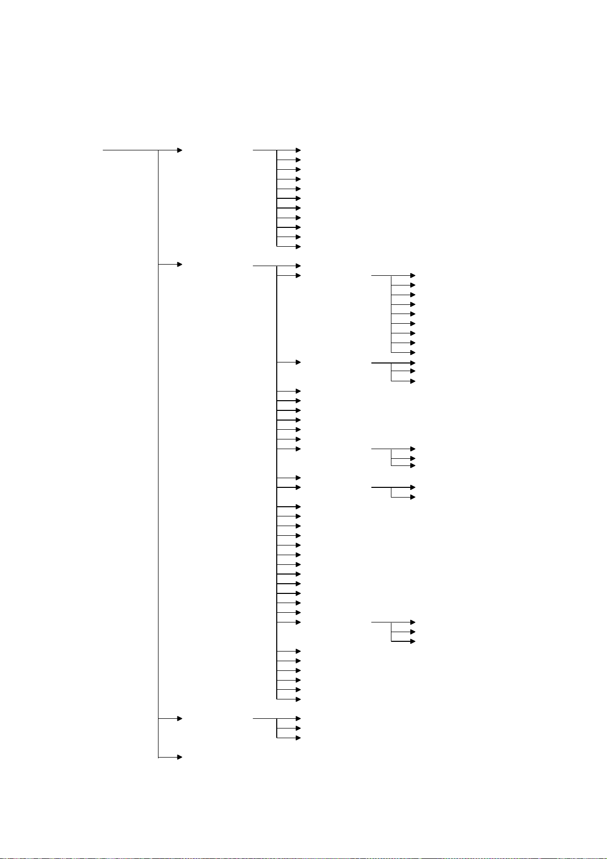
SERVICE PROGRAM MODE 1 October, 1999
4.2.2 SERVICE PROGRAM MODE MENU TREE
The following diagram shows the service mode menu tree.
SERVICE MODE
Service Menu 1
(Controller Service
Mode)
Service Menu 2
(Engine Service Mode)
BitSw#1 Set
BitSw#2 Set
BitSw#3 Set
BitSw#4 Set
NVRAM Clear 1
NVRAM Clear 2
NVRAM Clear 3
Couter Clear
Diag Error
Vender Maker
Service Print
A: Prn EngMainte
B: Service regist
C: Regist Sag
D: Fusing Times
E: Fusing Period
F: Fusing heat
G: LD Power
H: Developer bias
I: Developer data
J: Transfer set Tray
K: Developer init
L: Separate volt The front side
M: Tailing cntrl
N: Tailing papers
O: Toner supply
P: T sensor set
Q: Memory all clr
R: Free run
S: Input check
T: Output check
U: Fusing err clr
V: Test Pattern
W: EngFirm ver up
X: LoopBack test
Y: ROM version Engine Firm
Z: Engine S/N
1: Disp Eng ver
2: A3/11x17 Count
3: Change PCM Mes
4: FuserCount clr
5: PCU Count clr
S-Scan Reg Bypass
S-Scan Reg Bypass
S-Scan Reg Dplx
M-Scan Reg Tray1
M-Scan Reg Tray2
M-Scan Reg Tray3
M-Scan Reg Tray4
M-Scan Reg Bypss
M-Scan Reg Dplx
Tray1
Other Trays
Duplex
Bypass Tray
Duplex
The back side
Duplex Firm
Finisher Firm
Service Menu 3
(Service Tool)
End 4
HDD Test
HDD format
NIB read/write
G038M510.WMF
4-4
Page 91

1 October, 1999 PRINTER CONTROLLER SERVICE MODE
4.3 PRINTER CONTROLLER SERVICE MODE
Service Mode Table (Service Menu 1)
Title Description
A BitSw#1 Set
B BitSw#2 Set
C BitSw#3 Set
D BitSw#4 Set
E NVRAM Clear 1
F NVRAM Clear 2 Initializes the NVRAM on the controller.
G NVRAM Clear 3 Initializes the NVRAM on the NIB.
H Counter Clear Initializes all counters to zero.
I Diag Error Displays diagnostics error codes on the LCD.
J Vender Maker Select s t he vender name.
K Service Print Prints the service summary sheet.
Adjusts bit switch settings.
Note: Currently, the bit switches are not being used.
Initializes the controller NVRAM except bit switches,
NIB settings, and log data.
4.3.1 BIT SWITCH PROGRAMMING
1. Enter the SP mode and select “1.Service Menu1.”
2. Select A, B, C, or D for the desired bit switch, then press [Enter].
3. Press [Enter] in the “Bit Switch Set” menu.
4. Adjust the bit switch using the following keys.
•
[▲] [▼]: Move to the next bit.
•
[Escape]: Exit without saving changes.
•
[Enter]: Exit and save changes.
5. Press [Enter] to save changes and exit.
BIT SWITCHES
NOTE:
Currently the bit switches are not being used.
Tables
Service
4-5
Page 92

PRINTER CONTROLLER SERVICE MODE 1 October, 1999
4.3.2 NVRAM RESET
ø
CAUTION
Print the service summary report, controller configuration page, and NIB
configuration page before resetting the NVRAM(s).
DIAG. ERROR LOG AND PAPER TRAY SETTINGS RESET
This initializes the following settings in the controller NVRAM.
•
Controller diagnostics error log
•
Paper type settings for trays
•
Paper size setting for the by-pass tray
1. Enter the SP mode, and select “1. Service Menu”.
2. Select “E. NVRAM Clear 1”, then press [Enter].
3. Ensure that you have printed the service summary report, then press [Enter].
4. Press [Enter] to execute. Or press [Escape] to exit.
CONTROLLER NVRAM RESET
This initializes all the data in the controller NVRAM, except the NIB settings.
1. Enter the SP mode, and select “1. Service Menu”.
2. Select “F. NVRAM Clear 2”, then press [Enter].
3. Ensure that you have printed the service summary report and controller
configuration page, then press [Enter].
4. Press [Enter] to execute. Or press [Escape] to exit.
NIB NVRAM RESET
This initializes all the data in the NIB NVRAM.
1. Enter the SP mode, and select “1. Service Menu”.
2. Select “G. NVRAM Clear 3”, then press [Enter].
3. Ensure that you have printed the NIB configuration page, then press [Enter].
4. Press [Enter] to execute. Or press [Escape] to exit.
4-6
Page 93

1 October, 1999 PRINTER CONTROLLER SERVICE MODE
COUNTER RESET
This initializes all the print counters in the controller NVRAM. Refer to the service
summary report for the counters in the controller NVRAM.
1. Enter the Printer SP mode, and select “1. Service Menu”.
2. Select “H. Counter Clear”, then press [Enter].
3. Press [Enter] to reset all the print counters.
4. Press [Enter] to execute. Or press [Escape] to exit.
NOTE:
The total counter will not be cleared because the total counter data is
stored in the engine board.
4.3.3 POWER-ON DIAGNOSTICS ERROR DISPLAY
This displays the latest 8 error codes that were found during the power-on self-test.
Refer to chapter 7 (Troubleshooting) for details of the error codes.
1. Enter the SP mode, and select “1. Service Menu”.
2. Select “I. Diag Error”, then press [Enter].
3. Check the error codes on the LCD.
[▼] [▲]: Move to the previous/next code.
4. Press [Escape] to exit.
4.3.4 VENDER MAKER
This enables to select the vender name for the printer.
1. Enter the SP mode, and select “1. Service Menu”.
2. Select “K. Vender Maker”, then press [Enter].
1. Select the vender name using [▼] [▲].
2. Enter the digit using [▼] [▲].
3. Press [Enter] to execute. Or press [Escape] to exit.
4.3.5 SERVICE SUMMAR Y
This prints a summary of all the controller settings.
Tables
Service
1. Enter the Printer SP mode, and select “1. Service Menu”.
2. Select “L. Service Print”, then press [Enter].
3. Press [Enter] again to print the report.
4-7
Page 94

PRINTER CONTROLLER SERVICE MODE 1 October, 1999
Model Number / System Version / Unit Number
Lists the machine’s Plug&Play name, controller firmware version, and the controller
part number.
Program List
Lists the firmware module version.
Bit Switch
List the current bit switch settings.
NOTE:
Currently the bit switches are not being used.
Counter
List all the counters in the controller.
NOTE:
The total counter data is not stored in the printer controller.
Exception Information
List CPU exception error information. Designer use only.
System Logging / System Logging 2
Lists internal log data. Designer use only.
Option
Lists all the installed optional components.
4-8
Page 95

1 October, 1999 PRINTER ENGINE SERVICE MODE
4.4 PRINTER ENGINE SERVICE MODE
4.4.1 SERVICE MODE MENU
Service Mode (Service Menu 2)
Title Description
A Prn Eng Mainte Prints the engine information
B Service reg ist Man/sub scan registration 1-001/002
C Regist sag Paper feed timing 1-003
D Fusing times Fusing soft start adjustment 1-107
E Fusing period Fusing soft start settings 1-108
F Fusing heat Fusing temperature adjustment 1-105/106
G LD power LD power adjustment 2-103
H Developer bias Development bias adjustment 2-201
I Developer data Development data display 2-220
J Transfer set Transfer current adjustment 2-301
K Developer init Developer initial ization 2-801
L Separate volt Separation voltage adjustment 2-901
M Tailing cntrl Tailing correction (shift value) 2-906-1
N Tailing papers Tailing correction (interval) 2-906-2
O Toner supply Toner supply mode 2- 921
P T sensor set Standard Vt adjustment 2-926
Q Memory all clr Memory all clear 5-801
R Free run Free run mode 5-802
S Input check Input check mode 5-803
T Output check Output check mode 5-804
U Fusing err clr SC code reset 5-810
V Test Pattern Test pattern print 5-902
W EngFirm ver up Engine board firmware update 5-932
X LoopBack test Loop-back test (not used) 5-990
Y ROM version Displays the ROM number 7-801
Z Engine S/N Ser ial number programming 5- 811
1 Disp Eng ver Displays the engine version 9-999-9
2 A3/11x17 Count A3/DLT double count selection 5-104
3 Change PCM Mes Maintenance replacement warning 9-999-8
4 FuserCount clr Fusing counter clear
5 PCU Count clr PCU counter clear
Notes
(SP Mode)
Tables
Service
4-9
Page 96

PRINTER ENGINE SERVICE MODE 1 October, 1999
4.4.2 SERVICE MODE TABLES
Menu Level
Level 1 Level 2 Description
Prints the
engine
maintenance
information
A:
Prn Eng
Mainte
---
Function Settings
The following items are
printed.
·
Engine serial number
·
Firmware version
(Engine/Duplex
unit/Finisher)
·
Maintenance Counter
(Total counter/PCU
counter/Motor counter)
·
Engine settings
·
(Main/sub scan registration
for each trays, density
setting)
·
ID Sensor Error
·
Remaining amount of paper
·
Engine error logging
(last 10 error)
B:
Service
regist
S-Scan
Reg Tray
S-Scan
Reg
Bypss
S-Scan
Reg Dplx
Leading Edge
Registration
(Paper Trays)
Leading Edge
Registration
(Bypass feed)
Leading Edge
Registration
(Duplex)
Adjusts the printing leading
edge registration using the test
pattern.
Use the
or decrease.
s/t
keys to increase
-9.0 to +9.0
0.1
mm/step
0.0 mm
-12.5 to
+12.5
0.1
mm/step
0.0 mm
4-10
Page 97

1 October, 1999 PRINTER ENGINE SERVICE MODE
Menu Level
Level 1 Level 2 Description
M-Scan
Reg
Tray1
M-Scan
Reg
Tray2
Side-to-Side
Registration
(Paper Tray 1)
Side-to-Side
Registration
(Paper Tray 2)
Side-to-Side
Registration
(Paper Tray 3:
optional PFU
tray 1 or
optional LCT)
Side-to-Side
Registration
(Paper Tray 4:
optional PFU
B:
Service
regist
M-Scan
Reg
Tray3
M-Scan
Reg
Tray4
tray 2)
M-Scan
Reg
Bypss
Side-to-Side
Registration
(Feed from
Bypass Tray)
Side-to-Side
M-Scan
Reg Dplx
Registration
(Feed from
Duplex unit)
Paper Feed
Tray1
Timing
(Tray 1)
Paper Feed
C:
Regist
sag
Other
Trays
Timing
(2nd, 3rd, 4th
Paper Feed
and By-pass
Feed)
Paper Feed
Duplex
Timing
(Duplex)
Fusing Soft
Start
D:
Adjustment
Fusing
times
E:
Fusing
Fusing Soft
Start Setting
period
Function Settings
Adjusts the printing side-toside registration from paper
tray 1 using the test pattern.
Use the
s/t
keys to increase
or decrease.
Adjusts the printing side-toside registration from the
duplex unit using the test
pattern.
Adjusts the paper feed clutch
timing at registration. The
paper feed clutch timing
determines the amount of
paper buckle at registration. (A
larger setting leads to more
buckling.)
Adjusts the number of zerocross cycles of the fusing lamp
ac supply needed for the
fusing lamp power to reach
100%. Use a higher number if
the customer complains about
sudden power dropouts.
Selects whether the fusing
temperature control cycle is 1
or 3 seconds.
-9.0 to +9.0
0.1
mm/step
0.0 mm
-9.0 to +9.0
0.1
mm/step
0.0 mm
0 to 10
1 mm/step
5 mm
0 to 10
1 mm/step
6 mm
0: 3 times
1: 10 times
2: 20 times
0: 1 sec
1: 3 sec
Tables
Service
4-11
Page 98

PRINTER ENGINE SERVICE MODE 1 October, 1999
Menu Level
Level 1 Level 2 Description
Fusing
F:
Fusing
Temperature
Adjustment
heat
G:
LD power
LD Power
Adjustment
Development
H:
Developer
Bias
Adjustment
bias
I:
Developer
Developer
Data Display
data
Transfer
Tray
Current
(Trays)
J:
Transfer
set
Bypass
Tray
Transfer
Current
(Bypass Tray)
Transfer
Duplex
Current
(Duplex)
K:
Developer
Developer
Initialization
init
The front
side
L:
Separate
volt
Separation
voltage
adjustment
The back
side
Function Settings
Adjusts the fusing temperature
for printing.
First, the current fusing
temperature is displayed. Use
the
keys to scroll to the
▲/▼
temperature adjustment menu.
Adjusts the LD power.
Important: Do not change
the value.
Adjusts the development bias
during printing.
This can be adjusted as a
temporary measure if faint
printouts appear due to an
aging drum.
Displays the Vt, Vsp, Vsg,
Vdsp, Vtref, and Pspwm
values.
Adjusts the current applied to
the transfer roller during
printing from paper trays.
Adjusts the current applied to
the transfer roller during
printing from the by-pass tray.
Adjusts the current applied to
the transfer roller during
printing from the duplex unit.
Performs the developer
initialization. The machine
mixes the developer for 45 s
and displays the results.
Adjusts the voltage applied to
the separation plate at the
leading edge of the paper on
the front side.
Important: If the printouts
have pawl marks, increase this
voltage.
Adjusts the voltage applied to
the separation plate, at the
leading edge of the paper on
the rear side.
100 to 190
1°C/step
180°C
0 to 255
1 /step
129
-700 to -500
10 V/step
-600V
0: –2 µA
1: 0 µµµµA
2: +2 µA
3: +4 µA
-1200 to 4000
100 V/step
-1800 V
-1200 to 4000
100 V/step
-2100 V
4-12
Page 99

1 October, 1999 PRINTER ENGINE SERVICE MODE
Menu Level
Level 1 Level 2 Description
Tailing
Correction
(Shift Value)
M:
Tailing
cntrl
N:
Tailing
papers
Tailing
Correction
(Interval)
Toner Supply
Mode
O:
Toner
supply
Standard Vt Adjusts Vts (Vt for a new
P:
T sensor
set
Function Settings
Shifts the image across the
page at the interval specified
by the following SP mode (N:
Tailing papers).
When making many copies of
an original that contains
vertical lines (such as a table),
separation may not work
correctly, then a tailing image
will occur (ghosts of the
vertical lines will continue past
the bottom of the table). This
SP prevents this problem.
Changes the interval for the
image shift specified by the
previous SP mode (M: Tailing
cntrl).
Selects the toner supply mode.
Important:
Normally, only use “P+T
Control” setting. Change to
“T Control” temporarily if the
TD sensor is defective. Do not
use other settings; these are
for designer’s use only.
PCU). The TD sensor output is
adjusted to this value during
the TD sensor initial setting
process.
This SP is not effective when
“T Control” of the previous SP
mode (O: Toner supply) is
selected.
Important: Do not change
this value.
0.0 to 5.0
0.1
mm/step
0.0 mm
1 to 10
1 page/step
1 page
P+T
Control
Fixed 1
Fixed 2
T Control
0.00 to 5.00
0.01 V/step
2.30 V
Tables
Service
4-13
Page 100

PRINTER ENGINE SERVICE MODE 1 October, 1999
Menu Level
Level 1 Level 2 Description
Memory All
Clear
Q:
Memory
all clr
Free Run Perf orms a free run of the
R:
Free run
S:
Input Check Displays signals received from
Input
check
Output Check Turns on electrical
T:
Output
check
SC Code
U:
Reset
Fusing err
clr
V:
Test
Test Pattern
Print
Pattern
Engine Board
W:
EngFirm
Firmware
Update
ver up
X:
Loop-back test Internal loop-back test.
LoopBack
test
Function Settings
Resets all software counters
and returns all modes and
adjustments to the default
settings.
However, the following items
are not reset.
• Total counter
• PCU counter
• Fusing counter
• Engine serial number
Important: Turn the main
switch off/on after the reset.
This mode should be used
only when the EEPROM on
the engine board is replaced.
machine.
Press [Enter] to start.
Press [Enter] to stop.
Please note that the machine
will not stop immediately after
the [Enter] key is pressed.
sensors and switches.
See the “Input Check” section
for details.
components individually for
test purposes.
See the “Output Check”
section for details.
Resets the service call (fusing
error) conditions.
After performing this SP mode,
turn the main switch off and
on.
Prints a test pattern. This
machine could print only the
grid test pattern.
Downloads the system
program from an IC flash
memory card to the flash
memory on the engine board.
Refer to the “Program
Download” section for details.
Designer use only.
4-14
 Loading...