

Page 1

Russian Printer-2
SERVICE MANUAL
September 29, 2000
Subject to change
Page 2

I
IMPORTANT SAFETY NOTICES
PREVENTION OF PHYSICAL INJURY
1. Before disassembling or assembling parts of the copier and peripherals,
make sure that the printer power cord is unplugged.
2. The wall outlet should be near the printer and easily accessible.
3. Note that some components of the printer and the paper tray unit are
supplied with electrical voltage even if the main power switch is turned off.
4. If any adjustment or operation check has to be made with exterior covers off
or open while the main switch is turned on, keep hands away from electrified
or mechanically driven components.
5. The inside and the metal parts of the fusing unit become extremely hot while
the printer is operating. Be careful to avoid touching those components with
your bare hands.
HEALTH SAFETY CONDITIONS
1. Toner and developer are non-toxic, but if you get either of them in your eyes
by accident, it may cause temporary eye discomfort. Try to remove with eye
drops or flush with water as first aid. If unsuccessful, get medical attention.
OBSERVANCE OF ELECTRICAL SAFETY STANDARDS
1. The printer and its peripherals must be installed and maintained by a
customer service representative who has completed the training course on
those models.
2. The NVRAM on the system control board has a lithium battery which can
explode if replaced incorrectly. Replace the NVRAM only with an identical
one. The manufacturer recommends replacing the entire NVRAM. Do not
recharge or burn this battery. Used NVRAM must be handled in accordance
with local regulations.
Page 3
SAFETY AND ECOLOGICAL NOTES FOR DISPOSAL
1. Do not incinerate toner bottles or used toner. Toner dust may ignite
suddenly when exposed to an open flame.
2. Dispose of used toner, developer, and organic photoconductors in
accordance with local regulations. (These are non-toxic supplies.)
3. Dispose of replaced parts in accordance with local regulations.
4. When keeping used lithium batteries in order to dispose of them later, do not
put more than 100 batteries per sealed box. Storing larger numbers or not
sealing them apart may lead to chemical reactions and heat build-up.
LASER SAFETY
The Center for Devices and Radiological Health (CDRH) prohibits the repair of
laser-based optical units in the field. The optical housing unit can only be repaired
in a factory or at a location with the requisite equipment. The laser subsystem is
replaceable in the field by a qualified Customer Engineer. The laser chassis is not
repairable in the field. Customer engineers are therefore directed to return all
chassis and laser subsystems to the factory or service depot when replacement of
the optical subsystem is required.
!
WARNING
Use of controls, or adjustment, or performance of procedures other than
those specified in this manual may result in hazardous radiation exposure.
!
WARNING
WARNING: Turn off the main switch before atte mpting any of the
procedures in the Laser Unit section. Laser beams can seriously damage
your eyes.
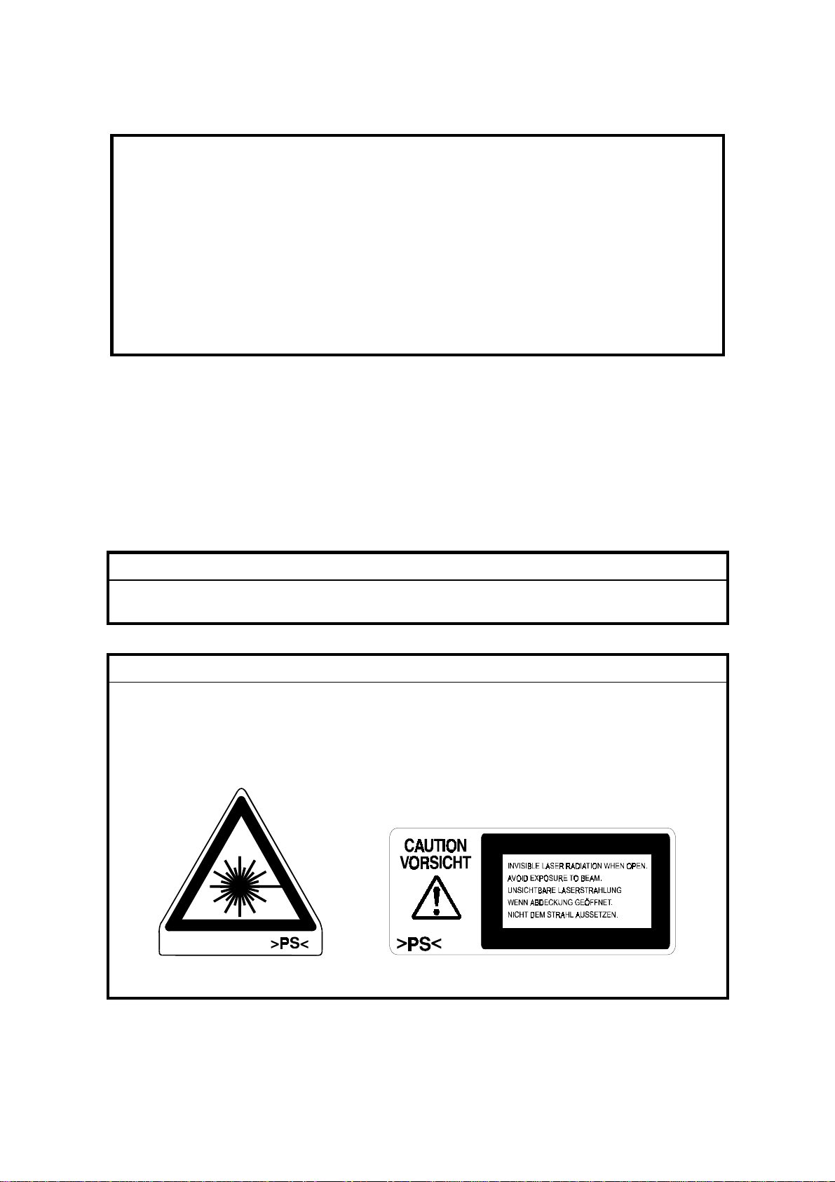
CAUTION MARKING:
Page 4

Trademarks
Microsoft®, Windows®, and MS-DOS® are registered trademarks of Microsoft
Corporation in the United States and /or other countries.
PostScript® is a registered trademark of Adobe Systems, Incorporated.
PCL® is a registered trademark of Hewlett-Packard Company.
Ethernet® is a registered trademark of Xerox Corporation.
PowerPC® is a registered trademark of International Business Machines
Corporation.
Other product names used herein are for identification purposes only and may be
trademarks of their respective companies. We disclaim any and all rights involved
with those marks.
Page 5

TABLE OF CONTENTS
1. OVERALL MACHINE INFORMATION....................................... 1-1
1.1 SPECIFICATIONS.....................................................................................1-1
1.1.1 GENERAL SPECIFICATIONS..........................................................1-1
1.1.2 SUPPORTED PAPER SIZES...........................................................1-2
1.2 SOFTWARE ACCESSORIES ...................................................................1-3
1.2.1 PRINTER DRIVERS.........................................................................1-3
1.2.2 UTILITY SOFTWARE.......................................................................1-3
1.2.3 SERVICE TOOLS.............................................................................1-3
1.3 MACHINE CONFIGURATION...................................................................1-4
1.3.1 SYSTEM COMPONENTS ................................................................1-4
1.4 ELECTRICAL COMPONENT DESCRIPTIONS ........................................1-6
1.5 BOARD STRUCTURE...............................................................................1-8
1.5.1 OVERVIEW ......................................................................................1-8
2. DETAILED SECTION DESCRIPTIONS ...................................... 2-1
2.1 DIFFERENT POINTS FROM BASE MODEL (G038) ................................2-1
2.1.1 OVERVIEW ......................................................................................2-1
2.1.2 PAPER FEED SECTION..................................................................2-2
2.1.3 LASER EXPOSURE SECTION........................................................2-2
2.1.4 DEVELOPMENT SECTION..............................................................2-2
2.1.5 ENGINE CONTROLLER BOARD.....................................................2-2
2.1.6 CONTROLLER BOARD ...................................................................2-3
3. INSTALLA TION .......................................................................... 3-1
3.1 INSTALLING THE MACHINE ....................................................................3-1
3.2 INSTALLING OPTIONAL UNITS...............................................................3-2
3.2.1 1,000-SHEET FINISHER..................................................................3-2
Installation Procedure ...........................................................................3-2
4. SERVICE TABLES...................................................................... 4-1
4.1 PRINTER CONTROLLER SERVICE MODE.............................................4-1
4.2 PRINTER ENGINE SERVICE MODE........................................................4-1
4.3 CONTROLLER FIRMWARE UPDATE......................................................4-2
4.3.1 FIRMWARE DOWNLOAD................................................................4-2
5. PREVENTIVE MAINTENANCE................................................... 5-1
6. REPLACEMENT AND ADJUSTMENT........................................ 6-1
6.1 LASER UNIT .............................................................................................6-1
6.1.1 CAUTION DECAL LOCATIONS.......................................................6-1
6.1.2 LASER UNIT ....................................................................................6-2
7. TROUBLESHOOTING................................................................ 7-1
i
Page 6

OPTIONS
500-SHEET FINISHER (G302)
1. REPLACEMENT AND ADJUSTMENT..................................G302-1
1.1 EXTERIOR ......................................................................................... G302-1
1.2 ENTRANCE UPPER GUIDE / PAPER EXIT UNIT............................. G302-4
1.3 ENTRANCE LOWER GUIDE .............................................................G302-5
1.4 PAPER EXIT UNIT GEAR / PADDLE ROLLER SOLENOID............. G302-5
1.5 STAPLER UNIT.................................................................................. G302-6
1.6 JOGGER TRAY UNIT ........................................................................ G302-6
1.7 PAPER EXIT SENSOR FEELER .......................................................G302-7
1.8 MAIN MOTOR .................................................................................... G302-7
1.9 JOGGER MOTOR.............................................................................. G302-8
1.10 CONTROL BOARD .......................................................................... G302-8
1.11 SHIFT TRAY UNIT ........................................................................... G302-9
2. DETAILED DESCRIPTIONS...............................................G302-10
2.1 OVERALL MACHINE INFORMATION ............................................. G302-10
2.1.1 COMPONENT LAYOUT.......................................................... G302-10
Mechanical component layout .....................................................G302-10
Drive layout.................................................................................. G302-11
2.1.2 ELECTRICAL COMPONENT DESCRIPTIONS ...................... G302-12
2.2 DETAILED SECTION DESCRIPTIONS ........................................... G302-14
2.2.1 SHIFT TRAY MECHANISM..................................................... G302-14
Stack height detection..................................................................G302-14
Shift tray up/down mechanism..................................................... G302-15
2.2.2 PAPER FEED.......................................................................... G302-16
Overview...................................................................................... G302-16
Straight feed out mode.................................................................G302-16
Shifting mode............................................................................... G302-17
Staple mode................................................................................. G302-19
2.2.3 JAM CONDITIONS.................................................................. G302-20
2.2.4 ERROR DETECTION.............................................................. G302-20
3. SPECIFICATIONS...............................................................G302-21
PAPER TRAY UNIT (A860): Common with Russian-P
1. OVERALL MACHINE INFORMAT ION..................................A860-1
1.1 SPECIFICATIONS.............................................................................. A860-1
1.2 MECHANICAL COMPONENT LAYOUT ............................................ A860-2
1.3 ELECTRICAL COMPONENT LAYOUT.............................................. A860-3
1.4 ELECTRICAL COMPONENT DESCRIPTION.................................... A860-4
1.5 DRIVE LAYOUT ................................................................................. A860-5
ii
Page 7

2. DETAILED DESCRIPTIONS.................................................A860-6
2.1 PAPER FEED AND SEPARATION MECHANISM ............................. A860-6
2.2 PAPER LIFT MECHANISM................................................................ A860-7
2.3 PAPER END DETECTION................................................................. A860-9
2.4 PAPER HEIGHT DETECTION ......................................................... A860-10
2.5 PAPER SIZE DETECTION............................................................... A860-12
2.6 SIDE AND END FENCES ................................................................ A860-13
Side Fences................................................................................. A860-13
End Fence ................................................................................... A860-13
3. REPLACEMENT AND ADJUSTMENT................................A860-14
3.1 FEED ROLLER REPLACEMENT..................................................... A860-14
3.2 TRAY MAIN BOARD REPLACEMENT ............................................ A860-15
3.3 TRAY MOTOR REPLACEMENT...................................................... A860-15
3.4 RELAY CLUTCH REPLACEMENT .................................................. A860-16
3.5 UPPER PAPER FEED CLUTCH REPLACEMENT .......................... A860-17
3.6 LOWER PAPER FEED CLUTCH REPLACEMENT ......................... A860-18
3.7 LIFT MOTOR REPLACEMENT........................................................ A860-19
3.8 PAPER END SENSOR REPLACEMENT......................................... A860-20
3.9 VERTICAL TRANSPORT SENSOR REPLACEMENT ..................... A860-20
3.10 PAPER SIZE SWITCH REPLACEMENT ....................................... A860-21
LCT (A862): Common with Russian-P
1. OVERALL MACHINE INFORMAT ION..................................A862-1
1.1 SPECIFICATIONS.............................................................................. A862-1
1.2 MECHANICAL COMPONENT LAYOUT ............................................ A862-2
1.3 ELECTRICAL COMPONENT LAYOUT.............................................. A862-3
1.4 ELECTRICAL COMPONENT DESCRIPTIONS ................................. A862-4
2. DETAILED SECTION DESCRIPTIONS ................................A862-5
2.1 PAPER FEED..................................................................................... A862-5
2.2 REVERSE ROLLER AND PICK-UP ROLLER RELEASE .................. A862-6
2.3 TRAY LIFT ......................................................................................... A862-7
2.4 NEAR END/END DETECTION........................................................... A862-8
2.5 RIGHT TRAY SIDE FENCE ............................................................... A862-9
2.6 LEFT TRAY REAR FENCE................................................................ A862-9
2.7 RIGHT TRAY PAPER END DETECTION ........................................ A862-10
3. REPLACEMENT AND ADJUSTMENT................................A862-11
3.1 DETACHING THE TRAY FROM THE MAINFRAME........................ A862-11
3.2 REAR FENCE HP SENSOR ............................................................ A862-11
3.3 CHANGING THE TRAY PAPER SIZE ............................................. A862-12
3.4 LEFT TRAY PAPER END SENSOR ................................................ A862-12
3.5 TRAY LIFT MOTOR ......................................................................... A862-13
3.6 TRAY MOTOR.................................................................................. A862-14
iii
Page 8

3.7 PAPER FEED CLUTCH AND RELAY CLUTCH............................... A862-15
3.8 PAPER FEED UNIT ......................................................................... A862-16
3.9 UPPER LIMIT, RIGHT TRAY PAPER END, AND
RELAY SENSORS ........................................................................... A862-17
3.10 REAR FENCE MOTOR .................................................................. A862-18
3.11 PICK-UP/PAPER FEED/REVERSE ROLLERS.............................. A862-19
BY-PASS UNIT (A899): Common with Russian-P
1 OVERALL MACHINE INFORMATION...................................A899-1
1.1 SPECIFICATIONS.............................................................................. A899-1
1.2 MECHANICAL COMPONENT LAYOUT ............................................ A899-1
1.3 ELECTRICAL COMPONENT LAYOUT.............................................. A899-2
1.4 ELECTRICAL COMPONENT DESCRIPTION.................................... A899-2
2 DETAILED DESCRIPTIONS..................................................A899-3
2.1 BASIC OPERATION........................................................................... A899-3
2.2 PAPER SIZE DETECTION................................................................. A899-4
3 REPLACEMENT AND ADJUSTMENT...................................A899-5
3.1 PAPER FEED ROLLER/FRICTION PAD/PAPER END SENSOR...... A899-5
3.2 PAPER SIZE SENSOR BOARD......................................................... A899-6
3.3 PAPER FEED CLUTCH ..................................................................... A899-7
INTERCHANGE UNIT (G531): Common with Russian-P
1. OVERALL MACHINE INFORMATION..................................G531-1
1.1 SPECIFICATIONS..............................................................................G531-1
1.2 MECHANICAL COMPONENT LAYOUT ............................................G531-2
1.3 DRIVE LAYOUT ................................................................................. G531-3
2. DETAILED DESCRIPTION ................................................... G531-4
2.1 JUNCTION GATE MECHANISM........................................................ G531-4
To the Exit Tray or Bridge Unit (for the Upper Tray on top of
the Bridge Unit, or the Finisher) ..................................................... G531-4
To the 1-bin Tray............................................................................G531-4
To the Duplex Unit ......................................................................... G531-4
3. REPLACEMENT AND ADJUSTMENT..................................G531-5
3.1 EXIT SENSOR REPLACEMENT........................................................G531-5
iv
Page 9

DUPLEX UNIT (G582) : The contents of manual are the same as
G529 manual.
1. OVERALL MACHINE INFORMATION..................................G529-1
1.1 SPECIFICATIONS..............................................................................G529-1
1.2 MECHANICAL COMPONENT LAYOUT ............................................G529-2
1.3 ELECTRICAL COMPONENT LAYOUT.............................................. G529-3
1.4 ELECTRICAL COMPONENT DESCRIPTION.................................... G529-4
1.5 DRIVE LAYOUT ................................................................................. G529-5
2. DETAILED DESCRIPTIONS.................................................G529-6
2.1 BASIC OPERATION...........................................................................G529-6
Larger than A4 lengthwise/LT Lengthwise..................................... G529-6
Up to A4 Lengthwise/LT lengthwise............................................... G529-7
2.2 FEED IN AND EXIT MECHANISM ..................................................... G529-8
When Paper is Fed Into Duplex Unit:............................................. G529-8
Inversion and Exit: ......................................................................... G529-8
3. REPLACEMENT AND ADJUSTMENT..................................G529-9
3.1 COVER REMOVAL ............................................................................ G529-9
3.2 ENTRANCE SENSOR REPLACEMENT.......................................... G529-10
3.3 EXIT SENSOR REPLACEMENT...................................................... G529-11
BRIDGE UNIT (G583): The contents of manual are the same as
A897 manual
1. OVERALL MACHINE INFORMAT ION..................................A897-1
1.1 SPECIFICATIONS.............................................................................. A897-1
1.2 MECHANICAL COMPONENT LAYOUT ............................................ A897-2
1.3 ELECTRICAL COMPONENT LAYOUT.............................................. A897-3
1.4 ELECTRICAL COMPONENT DESCRIPTION.................................... A897-4
1.5 DRIVE LAYOUT ................................................................................. A897-5
2. DETAILED DESCRIPTION ...................................................A897-6
2.1 JUNCTION GATE MECHANISM........................................................ A897-6
3. REPLACEMENT AND ADJUSTMENT..................................A897-7
3.1 BRIDGE UNIT DRIVE MOTOR REPLACEMENT .............................. A897-7
3.2 TRAY EXIT SENSOR REPLACEMENT ............................................. A897-8
3.3 RELAY SENSOR REPLACEMENT.................................................... A897-8
v
Page 10

FINISHER (A681): Common with Russian-P
1. OVERALL MACHINE INFORMAT ION..................................A681-1
1.1 SPECIFICATIONS.............................................................................. A681-1
1.2 MECHANICAL COMPONENT LAYOUT ............................................ A681-2
1.3 ELECTRICAL COMPONENT LAYOUT.............................................. A681-3
1.4 ELECTRICAL COMPONENT DESCRIPTIONS ................................. A681-4
1.5 DRIVE LAYOUT ................................................................................. A681-6
2. DETAILED DESCRIPTIONS.................................................A681-7
2.1 JUNCTION GATE MECHANISM........................................................ A681-7
Staple Mode................................................................................... A681-7
No staple Mode.............................................................................. A681-7
2.2 JOGGER UNIT PAPER POSITIONING MECHANISM....................... A681-8
2.3 EXIT GUIDE PLATE OPEN/CLOSE MECHANISM............................ A681-9
2.4 STAPLER ......................................................................................... A681-10
2.5 FEED OUT MECHANISM ................................................................ A681-11
2.6 SHIFT TRAY UP/DOWN MECHANISM ........................................... A681-12
2.7 SHIFT TRAY SIDE-TO-SIDE MECHANISM..................................... A681-13
2.8 JAM CONDITIONS........................................................................... A681-14
2.9 TIMING CHARTS ............................................................................. A681-15
2.9.1 NO STAPLE MODE (A4 SIDEWAYS, 3 SHEETS/2SETS)...... A681-15
2.9.2 STAPLE MODE (A4 SIDEWAYS, 2 SHEETS/2 SETS)........... A681-16
3. SERVICE TABLE................................................................A681-17
3.1 DIP SWITCH TABLE........................................................................ A681-17
3.2 TEST POINTS.................................................................................. A681-17
3.3 FUSES ............................................................................................. A681-17
4. REPLACEMENT AND ADJUSTMENT................................A681-18
4.1 COVER REMOVAL .......................................................................... A681-18
Front Door.................................................................................... A681-18
Front Cover.................................................................................. A681-18
Rear Cover .................................................................................. A681-18
Upper Cover ................................................................................ A681-18
Lower Left Cover ......................................................................... A681-19
Front Shift Tray Cover.................................................................. A681-19
Rear Shift Tray Cover .................................................................. A681-19
Shift Tray ..................................................................................... A681-19
4.2 ENTRANCE SENSOR REPLACEMENT.......................................... A681-20
4.3 EXIT SENSOR REPLACEMENT...................................................... A681-21
4.4 STACK HEIGHT SENSOR REPLACEMENT ................................... A681-22
4.5 POSITIONING ROLLER REPLACEMENT....................................... A681-23
4.6 STAPLER REPLACEMENT ............................................................. A681-24
vi
Page 11

MAILBOX (G518): Common with Russian-P
1. OVERALL MACHINE INFORMATION..................................G518-1
1.1 SPECIFICATIONS..............................................................................G518-1
1.2 COMPONENT LAYOUT..................................................................... G518-2
1.2.1 MECHANICAL COMPONENT LAYOUT.................................... G518-2
1.2.2 DRIVE LAYOUT ........................................................................ G518-2
1.3 ELECTRICAL COMPONENT DESCRIPTIONS ................................. G518-3
2. DETAILED DESCRIPTIONS.................................................G518-5
2.1 BASIC OPERATION...........................................................................G518-5
2.2 PAPER OVERFLOW DETECTION .................................................... G518-6
2.2.1 OVERVIEW ............................................................................... G518-6
2.2.2 DETECTION TIMING ................................................................ G518-6
2.3 PAPER MISFEED DETECTION TIMING ........................................... G518-7
3. REPLACEMENT AND ADJUSTMENT..................................G518-9
3.1 EXTERIOR COVER REMOVAL ......................................................... G518-9
3.2 TRAY OVERFLOW AND VERTICAL TRANSPORT SENSOR
REPLACEMENT .............................................................................. G518-10
3.3 MAIN MOTOR REPLACEMENT ...................................................... G518-11
vii
Page 12

29 September, 2000 SPECIFICATIONS
1. OVERALL MACHINE INFORMATION
1.1 SPECIFICATIONS
1.1.1 GENERAL SPECIFICATIONS
Printing Speed: Maximum 32 pages per minute (A4/LT LEF)
(25 pages: duplex printing)
Printer Language: PCL 6 / PCL 5e
PostScript 3
Resolution: Max. 600 dpi (PCL 6/PCL5e/PS3)
Resident Fonts: PCL:
35 Intellifonts
10 True Type fonts
1 Bitmap font
PS3:
136 fonts (24 Type 2 fonts, 112 Type 14 fonts)
Host Interface: Bi-directional IEEE1284 parallel x 1 (Standard)
Ethernet (100 Base-TX/10 Base-T for TCP/IP, IPX/SPX,
NetBEUI, Apple Talk)
Printing Paper Size: Maximum: A3/11" x 17"
Minimum:
1st paper Tray: A5 SEF
2nd paper Tray: A6 SEF
By-pass: A6/ 90 x 148 mm SEF
Overall
Information
(Refer to section 1.1.2, "Supported Paper Size".)
Printing Paper
Weight:
Print Paper
Capacity:
1st paper tray: 60 to 105 g/m
2nd paper tray: 60 to 157 g/m
By-pass Tray: 60 to 200 g/m
1st and 2nd paper tray: 500 sheets x 2
Optional paper tray unit:
2
(16 to 28 lb.)
2
(16 to 42 lb.)
2
(16 to 110 Index)
500 sheets x 2
Optional LCT
1000 sheets x 2
Optional by-pass tray:
100 sheets
Output Paper
Capacity:
Standard output tray: 500 sheets
Optional 1000-finisher: 1,000 sheets
Optional 500-finisher: 500 sheets
Optional 4-bin mailbox: 500 sheets total
First Print Speed: 5 seconds or less (A4/LT LEF, 1st tray)
Warm-up Time Less than 45 seconds
1-1
Page 13

SPECIFICATIONS 29 September, 2000
Memory:
Standard 32 MB, up to 160 MB with optional DIMM.
Power Source: 120 V, 60 Hz: More than 10 A (for North America)
220 V - 240 V, 50/60 Hz: More than 6.0 A (for Europe)
Power Consumption:
120V 230V
Maximum
(Full Option)
Printing 620W or less 620W or less
Energy Saver
(Mode 1)
980W or less 980W or less
25 W or less 25 W or less
Noise Emission:
Mainframe Only Full System
Sound Power Lev el
Printing 65 dB or less 71 dB or less
Stand-by 40 dB or less 40 dB or less
NOTE: The above measurements were made in accordance with ISO 9296 at
the operator position.
Dimensions (W x D x H): 550 x 548 x 516 mm
Weight:
Approximately 40 kg
1.1.2 SUPPORTED PAPER SIZES
No differences from base model (G038).
Refer to the Field Service Manual for G308.
1-2
Page 14

29 September, 2000 SOFTWARE ACCESSORIES
1.2 SOFTWARE ACCESSORIES
The printer drivers and utility software are provided on one CD-ROM. An auto-run
installer allows you to select which components to install. The service tools are not
provided on the CD-ROM.
1.2.1 PRINTER DRIVERS
Printer Language Windows 95/98 Windows 2000 Windows NT4.0 Macintosh
PCL 6 Yes Yes Yes No
PCL 5e Yes Yes Yes No
PS3 Yes Yes Yes Yes
NOTE: 1) The printer drivers for Windows NT 4.0 are only for the Intel x86
platform. There is no Windows NT 4.0 printer driver for PowerPC, Alpha,
or MIPS platforms.
2) The PS3 drivers are all genuine AdobePS drivers. A PPD file for each
operating system is provided with the driver.
3) The PS3 drivers for Macintosh support Mac OS 7.1 or later versions.
Overall
Information
1.2.2 UTILITY SOFTWARE
Software Description
Agfa Font Manager
(Win 95/98, 2000, NT4)
Printer Manager for Admin
(Win 95/98, 2000, NT4)
Printer Manager for Client
(Win95/98, 2000, NT4)
Port Navi
(Win95/98, 2000, NT4)
Multi-Direct Print
(Win95/98, 2000, NT4)
Acrobat Reader Document reader for PDF format
A font management utility with screen fonts for the printer.
A printer management utility for network administrators. NIB
setup utilities are also available.
A printer management utility for client users.
A peer to peer print utility over a TCP/IP network. This provides
parallel printing and recovery printing function.
A utility for peer-to-peer printing over a NetBEUI or TCP/IP
network.
1.2.3 SERVICE TOOLS
Software Description
NBTFTP NIB firmware update utility for use on a NetBEUI network.
This utility is not on the Driver and Utilities CD-ROM; it is issued
separately as a service tool
1-3
Page 15

MACHINE CONFIGURATION 29 September, 2000
1.3 MACHINE CONFIGURATION
1.3.1 SYSTEM COMPONENTS
[H]
[G]
[I]
[J]
[A]
[B]
[C]
[D]
[F]
1-4
[E]
G062V502.WMF
Page 16

29 September, 2000 MACHINE CONFIGURATION
Item
Main Unit G062 I User
Option
Paper Tray Unit - 2
trays
LCT A862
By-pass Tray A899
Interchange Unit G531 B User Common with Russian-P
Duplex Unit G582 C User
4-bin Mailbox G518 A
Bridge Unit G583 J User New model
500-sheet Finisher G302 H User New model
1000-sheet
Finisher
Internal Option
HDD G690 User Common with Stinger-
Memory 32MB G578 User
Memory 64MB G579 User
Memory 128MB G580 User
Others
Maintenance Kit G719
Machine
Code
A860
A681 G Service
No.
F
E
D
Installable
by
User
(Note 1)
User
(Note 1)
User Common with Russian-
(Note 2, 3)
User
(Note 2)
(Note 4)
Common with Stinger-
C/Russian-C/P with
modified motor.
Common with Russian-
C/P with modified tray
motor.
C/P
New model
Common with Russian-P
with modified motor and
driver board.
Common with RussianC/P/NAD
C/Russian-C/P
Remarks
Overall
Information
NOTE: 1) Only one of these options can be installed on the machine.
2) Requires the installation of the Interchange unit.
3) Requires the installation of the memory option.
4) The Bridge unit must be installed together with the 1000 sheet Finisher.
Either the LCT or Paper Tray Unit (2 trays) must also be installed.
1-5
Page 17

ELECTRICAL COMPONENT DESCRIPTIONS 29 September, 2000
1.4 ELECTRICAL COMPONENT DESCRIPTIONS
Refer to the electrical component layout on the reverse side of the point-to-point
diagram for component location.
A polygonal mirror motor fan (M7) was added.
Symbol Name Function
Motors
M1 Polygonal Mirror Turns the polygonal mirror.
M2 Main Motor Drives the main unit components.
M3 Exhaust Fan Removes heat from around the fusing unit.
M4 Upper Paper Lift Raises the bottom plate in the 1st paper tray.
M5 Lower Paper Lift Raises the bottom plate in the 2nd paper tray.
M6 Toner Supply
M7
Magnetic Clutches
MC1 Upper Paper Feed Starts paper feed from the 1st paper tray.
MC2 Lower Paper Feed Starts paper feed from the 2nd paper tray.
MC3 Upper Paper Transport Drives the upper transport rollers.
MC4 Lower Paper Transport Drives the lower transport rollers.
MC5 Registration Drives the registration rollers.
Switches
SW1 Main Switch
SW2 Right Upper Cover Detects whether right upper cover is open or not.
SW3 Right Cover
SW4 Right Lower Cover Detects whether right lower cover is open or not.
SW5 Upper Paper Size
SW6 Lower Paper Size
SW7 Special Paper
SW8 New PCU Detect Detects when a new PCU is installed.
SW9 Front Cover Safety
Sensors
S1 Toner Density (TD)
S2 1st Paper End
S3 1st Paper End
S4 Image Density (ID)
S5 Paper Overflow Detects paper overflow condition.
S6 Paper Exit Detects misfeeds.
S7 Upper Relay Detects misfeeds.
Polygonal Mirror Motor
Fan
Rotates the toner bottle to supply toner to the
development unit.
Removes heat from around the optical unit
Provides power to the machine. If this is off, there is
no power supplied to the machine.
Cuts the +5VLD and +24V dc power line and
detects whether the right cover is open or not.
Determines what size of paper is in the upper
paper tray.
Determines what size of paper is in the Lower
paper tray.
Determines the special paper is in the lower paper
tray.
Cuts the +5VLD and +24V dc power line and
detects whether the front cover is open or not.
Detects the amount of toner inside the
development unit.
Informs the CPU when the 1st paper tray runs out
of paper.
Informs the CPU when the 2nd paper tray runs out
of paper.
Detects the density of various patterns and the
reflectivity of the drum for process control.
1-6
Page 18

29 September, 2000 ELECTRICAL COMPONENT DESCRIPTIONS
Symbol Name Function
S8 Lower Relay Detects misfeeds.
S9 Registration
S10 1st Paper Lift
S11 2nd Paper Lift
Detects misfeeds and controls registration clutch
off-on timing.
Detects when the paper in the 1st paper tray is at
the feed height.
Detects when the paper in the 2nd paper tray is at
the feed height.
S12 1st Paper Height - 1 Detects the amount of paper in the 1st paper tray.
S13 1st Paper Height - 2 Detects the amount of paper in the 1st paper tray.
S14 2nd Paper Height - 1 Detects the amount of paper in the 2nd paper tray.
S150 2nd Paper Height - 2 Detects the amount of paper in the 2nd paper tray.
PCBs
PCB1 Engine Board Controls all printer engine functions.
PCB2 Printer Controller Board Controls the printer functions
PCB3 Network Interface Board Network interface board
PCB4 PSU (Power Supply Unit)
Provides dc power to the system and ac power to
the fusing lamp and heaters.
PCB5 LDD (Laser Diode Driver) Controls the laser diode.
PCB6 Operation Panel Controls the operation panel.
PCB7 High Voltage Supply
Supplies high voltage to the drum charge roller,
development roller, and transfer roller.
PCB8 Memory (Option) Expands memory capacity.
Lamps
L1 Fusing Lamp Heats the hot roller.
L2 Quenching Lamp
Neutralizes any charge remaining on the drum
surface after cleaning.
Others
TF1 Fusing Thermofuse
Opens the fusing lamp circuit if the fusing unit
overheats.
TH1 Fusing Thermistor Detects the temperature of the hot roller.
LSD 1
Laser Synchronization
Detector
Detects the laser beam at the start of the main
scan.
Overall
Information
1-7
Page 19

BOARD STRUCTURE 29 September, 2000
1.5 BOARD STRUCTURE
1.5.1 OVERVIEW
The PS module is contained in the Printer Controller Board.
1-8
G062V501.WMF
Page 20

29 September, 2000 DIFFERENT POINTS FROM BASE MODEL (G038)
2. DETAILED SECTION DESCRIPTIONS
2.1 DIFFERENT POINTS FROM BASE MODEL (G038)
2.1.1 OVERVIEW
The following points are different from the base model (G038)
1. Printing Speed
G062 Base Model (G038)
Printing Speed
(25 ppm duplex printing)
To obtain the above higher printing speed, the following sections were changed
from the base model G038.
1) Paper feed
2) Laser exposure
3) Development (Quenching)
32 ppm
27 ppm
(22 ppm duplex printing)
Detailed
Descriptions
4) Engine controller
5) Printer controller
2. Controller features
The following features were added.
1) Locked print
2) Sequential stack
2-1
Page 21

DIFFERENT POINTS FROM BASE MODEL (G038) 29 September, 2000
2.1.2 PAPER FEED SECTION
The followings differ from the base model (G038) in the paper feed section to get
higher printing speed.
1. Registration roller
The diameter of the gears were changed.
2. Registration pressure roller and pressure springs
The diameter of the roller and pressure force of springs were changed.
3. Relay rollers
Diameter of upper and lower relay roller is changed.
4. The number of flywheels was changed from 3 to 2 in order to stabilize the
rotation of the main motor.
2.1.3 LASER EXPOSURE SECTION
The following optical unit items differ from the base model(G038).
1. Polygonal Mirror Motor
An increase in the speed of the polygonal mirror motor enables an increase in
the printing speed.
G062 Base Model (G038)
Mirror motor revolution
speed
38,000 rpm 31,000 rpm
2. Polygonal Mirror Motor Fan
A polygonal mirror motor fan was added to remove heat from around the
Optical unit.
2.1.4 DEVELOPMENT SECTION
The quenching lamp was changed to increase the amount of light.
2.1.5 ENGINE CONTROLLER BOARD
1. The fusing temperature in energy saver mode was changed.
Energy saver mode G062 Base Model (G038)
Level 1
Level 2 Off Off
140 °C 60 °C
2. The hardware and firmware were changed to increase the printing speed.
2-2
Page 22

29 September, 2000 DIFFERENT POINTS FROM BASE MODEL (G038)
2.1.6 CONTROLLER BOARD
The following items differ from the base model:
1. A PS DIMM was included in the printer controller board.
2. CPU and standard memory size were changed for higher performance.
G062 Base Model (G038)
CPU
Standard Memory
RM5261 250MHz Vr.4310 167MHz
32 MB 16 MB
3. New controller features
Locked print
This function protects users' confidentiality for printouts using a shared printer
when anyone wishes to print confidential documents. With this function,
documents will not print out unless the user enters a valid password, which
was entered in the Printer Driver when sending the print job(s), at the printer
controller panel. This function is only applicable when the optional HDD is
attached.
Capacity
Max. Storing pages
Max. Job storing
Max. Overflow job record
Max. Storing capacity (HDD)
2000 pages*
30 jobs*
20 jobs
2GBMB
Detailed
Descriptions
*: These figures are for both the sample and locked print functions.
Sequential stack
This function, with optional mailbox, enables the user to continue printing by
automatically changing output trays when the current output tray becomes full.
To enable this function, select "Sequential Stack" mode from the operation
panel.
The output tray will automatically be chosen as follows.
(Case 1: Finisher is attached)
Finisher Tray -> Mailbox Tray 1 -> Mailbox Tray 2 -> Mailbox Tray 3 ->
Mailbox Tray 4
* Standard Tray (on the bridge unit) will not be used as output tray.
(Case 2: Finisher is not attached)
Standard Tray -> Mailbox Tray 1 -> Mailbox Tray 2 -> Mailbox Tray 3 ->
Mailbox Tray 4
2-3
Page 23

DIFFERENT POINTS FROM BASE MODEL (G038) 29 September, 2000
Other conditions and remarks are as follows.
1) The tray will automatically change after the full stack detection sensor is
activated for each tray.
2) When Mailbox Tray 4 is full, the "Remove Paper All Tray" message appears
on the LCD.
3) When all of the paper is removed from all of the trays (cancelled full stack
detection), printing will restart from the Finisher Tray (Case 1) or the
Standard Tray (Case 2).
4) When "Collation" is selected, SHIFT/SORT will be enabled on the Finisher
Tray, but rotate collation will be disabled for the Mailbox Trays. (Case 1)
5) When "Collation" is selected, rotate collation will be enabled. (Case 2)
6) When "Staple" is selected, it will be enabled on the Finisher Tray.
7) When “Sequential Stack” is selected during continuous multiple print jobs,
the tray will not be change between 2 different jobs. It will continue to output
paper to the current tray until the tray becomes full. Then, it will switch to
another tray.
8) If any tray is out of order, that particular tray will be skipped and if there are
no trays to change to, the machine will indicate "Remove Paper All Tray", as
in step 2.
2-4
Page 24

29 September, 2000 INSTALLING THE MACHINE
3. INSTALLATION
3.1 INSTALLING THE MACHINE
Refer to the Setup Guide for information about the installation environment and
instructions on how to install and set up this machine. Installation procedures for
the following items are described.
• Paper Tray (2 trays)
• LCT
• By-pass Tray Unit
• Interchange Unit
• Duplex Unit
• 4-bin Mailbox Unit
• Bridge Unit
• 500-Sheet Finisher
• Memory (SDRAM DIMM)
• HDD Unit
InstallationInstallation
If the customer has a service contract with a meter click system and counter
indication is required, set up the counter with an SP mode as follows:
1. Enter the Service mode.
2. Set 1 at the bit1 of “C. BitSw #3 set” in Service Menu1.
3. Exit Service mode
4. Confirm the counter is indicated on operation panel by pressing [Menu] and
[Enter] keys.
3-1
Page 25

INSTALLING OPTIONAL UNITS 29 September, 2000
3.2 INSTALLING OPTIONAL UNITS
!
CAUTION
Before installing this option, do the following:
1. Print out all data in the printer buffer.
2. Turn off the switch and disconnect the power cord.
3.2.1 1,000-SHEET FINISHER
NOTE: The following options must be installed before installing this finisher:
• Bridge Unit (G583)
• Paper Tray Unit (G532) or LCT (G539)
Installation Procedure
1. Unpack the finisher and remove the tapes.
A681I503.WMF
2. Install screw [A] loosely.
3. Hang the front stand [B] on the screw
that was installed in step 2.
4. Secure the front stand (3 screws,
including screw [A]).
5. Install the rear stand [C] (2 screws).
A681I504.WMF
[A]
[C]
[B]
A681I101.WMF
3-2
Page 26

29 September, 2000 INSTALLING OPTIONAL UNITS
6. Pull out the stapler unit [D].
7. Draw out the locking lever [E] (1 screw).
8. Align the finisher on the stands, and lock it in
place by pushing the locking lever.
9. Secure the locking lever (1 screw) and push
the stapler unit into the finisher.
10. Secure the finisher (1 screw from
step 2).
11. Adjust the securing knobs [F] under
the front and rear stand until the
finisher is perpendicular to the floor.
[G]
12. Install the shift tray [G] (1 snap ring).
NOTE: Make sure that the three pegs
[H] fit into the slots [I]
properly.
[H]
13. Connect the finisher cable [J] to the
optional bridge unit.
14. Turn on the main switch and check
[I]
the finisher operation.
[D]
[E]
A681I502.WMF
[J]
InstallationInstallation
A681I103.WMF
[F]
End of procedure
3-3
Page 27

29 September, 2000 PRINTER CONTROLLER SERVICE MODE
4. SERVICE TABLES
4.1 PRINTER CONTROLLER SERVICE MODE
The following Bit Switches were added to the base model G038.
Title Description Function / Note
C BitSw #3 Set
Bit 1 : Counter indication
0: Disable (default)
1: Enable
Bit 2 : Job uniting
0: Disable (default)
1: Enable
Bit 3 : HP GL/2 Emulation
0: Normal (default)
1: Enhancing thin lines
Bit 4 : DAZEL compatibility
0: Enable (default)
1: Disable
Bit 5 : Not used
Bit 6 : Not used
Bit 7 : Not used
Bit 8 : Border pattern printing
0: Disable (default)
1: Enable
The customer can view the
Charge Counter on the LCD
panel using the “Menu”
function.
Uniting jobs if PC sends the
next job before printer
completes the current job.
(see note)
If thin lines can not be
reproduced with CAD
application, set this bit “1”.
If malfunction occurs on the
printer because of job
command, disabling this
switch.
The border pattern is printed
on the Configuration sheet for
leading edge/side-to-side
registration adjustment.
Tables
Service
NOTE: When enabling this function, the “Jog log” does not show the actual job,
and job canceling is applied to whole combined jobs.
4.2 PRINTER ENGINE SERVICE MODE
Only the title of the following service menu differs from the base model G038.
Menu Level
Level 1 Level 2 Description
3:
Notify PM
Alarm
Maintenance
replacement
warning and
Select enabling / disabling PM
alert and printing stop after 5K
printing from the alert.
4-1
Function Settings
0.Alert only
1.Stop printing
2.No message
Page 28

CONTROLLER FIRMWARE UPDATE 29 September, 2000
4.3 CONTROLLER FIRMWARE UPDATE
4.3.1 FIRMWARE DOWNLOAD
The PS module is contained in the controller. The following two types of firmware
can be individually downloaded through the IC card connector on the controller.
- Controller firmware including PS module
- NIB firmware
The procedure is the same as base model G038.
4-2
Page 29

29 September, 2000
5. PREVENTIVE MAINTENANCE
No differences from the base model G038.
Refer to the Field Service Manual for G038.
Preventive
Maintenance
5-1
Page 30

29 September, 2000 LASER UNIT
6. REPL ACEMENT AND ADJUSTMENT
6.1 LASER UNIT
!
WARNING
Turn off the main power switch and unplug the machine before attempting
any of the procedures in this section. Laser beams can seriously damage
your eyes.
6.1.1 CAUTION DECAL LOCATIONS
The CAUTION decal is located in the laser section as shown below.
G062R500.WMF
G062R501.WMF
Adjustment
Replacement
6-1
Page 31

LASER UNIT 29 September, 2000
6.1.2 LASER UNIT
[B]
[C]
[A]
G062R161.WMF
[D]
[F]
[E]
G062R162.WMF
G062R508.WMF
!
WARNING
Turn off the main switch and unplug the machine before attempting any of
the procedures in this section. Laser beams can seriously damage your
eyes.
1. Remove the optional finisher and/or bridge unit, if these units have been
installed.
2. Remove the front cover [A] (2 pins).
3. Remove the right front cover [B] (1 screw).
4. Swing up the toner bottle lever. Then, remove the inner cover [C] (5 screws).
5. Remove the paper exit tray [D] (1 hook [E]).
6. Remove the polygon mirror motor fan together with holder [F]. (1 connector, 2
screws)
6-2
Page 32

29 September, 2000
7. TROUBLESHOOTING
No differences from the base model G038.
Refer to the Field Service Manual for G038.
7-1
Trouble-
shooting
Page 33

Polygonal Mirror
M7
-2
CN131-1
24 V
CN105
Paper Tray
Paper
Lift
Sensor
Lift Motor
High
Voltage
-3
-4
Feed Back-B [Analog]
-5
-6
s
PWM-C [ 5]
Feed Back-C [Analog]
s
PWM-T-I [ 5]
-7
Supply
PCB 7
-8
s
PWM-T-V [ 5]
Feed Back-T-I [Analog]
-9
-10
Feed Back-T-V [Analog]
-11
s
PWM-D [ 5]
-12
-13
+24V
Feed Back-D [Analog]
+5V
-14
GND
Paper
Exit Sensor
S6
-2
-1
CN2-3
-2
-3
CN324-1
t
GND
Paper Exit [ 5]
CN3-3
-4
+5V
Paper
-2
-5
GND
Overflow Sensor
S5
-1
-6
t
Paper Overflow [ 5]
CN4-2
-7
+5V
Right Upper
Cover Sensor
SW2
-1
-8
s
GND
Cover Open [ 5]
CN304-A1
t
Note 1
4th Feed Clutch [ 24]
M2
-4
CN105-5
s
s
Motor Up [ 24]
Motor Down [ 24]
-A2
-A3
-A4
t
t
Relay Clutch [ 24]
3rd Feed Clutch [ 24]
S1
-2
CN105-3
+5V
s
Paper Lift [ 5]
-A5
-A6
s
s
s
Paper Height-B [ 5]
Paper Height-A [ 5]
Paper Tray Unit Set [ 5]
-1
CN101-1
GND
-A7
-A8
s
Bank-Hight [ 5]
[24/0] A
t
4th Paper Size [ 5]
Motor Fan
RSVFAN
1st Paper
Lift Sensor
S10
-6
-7
CN309-5
s
GND
1st Paper Lift Sensor [ 5]
+5V
-1
1st Paper
M4
s
Motor-up [ 24]
Lift Motor
-2
2nd Paper
2n Paper
Lift Sensor
Lift Motor
S11
M5
-8
-9
-3
-4
-10
+5V
s
GND
s
s
Motor-up [ 24]
Motor-down [ 24]
2nd Paper Lift Sensor [ 5]
-2
CN1-1
-2
CN221-1
s
s
Set [ 5]
Motor-down [ 24]
TD Sensor
S1
-3
-3
GND
TD Sensor [Analog]
-4
-4
CN203-2
+5V
GND
New PCU
Detect SW
SW8
-1
Exhaust Fan
M3
-2
CN130-1
t
s
+24V
Fan Lock [ 5]
New PCU [ 5]
-3
CN205-1
t
Exhaust Fan [ 24]
Toner Supply
Motor
M6
t
Supply Motor [ 24]
-2
-3
+24 V
Quenching
Lamp
L2
-4
CN306-1
t
+24 V
Quenching Lamp [ 24]
1st Paper
End Sensor
S2
-2
s
GND
1st Paper End [ 5]
1st Paper
Feed Clutch
Upper Relay
Clutch
2nd Paper
End Sensor
Lower
-2
CN307-1
GND
t
Upper Relay Clutch [ 24]
Relay Sensor
Right Lower
Cover SW
2nd Paper
Feed Clutch
Lower
1st Paper
Relay Clutch
1st Paper
Height-1 Sensor
S3
S8
SW4
MC2
-3
-4
-5
-6
-7
-8
-10
GND
+24
+5V
s
s
GND
Door Open [ 5]
Lower Relay [ 5]
+5V
s
2nd Paper End [ 5]
S12
MC4
-2
-3
-4
-13
t
Lower Relay Clutch [ 24]
CN308-1
s
GND
1st Paper Height-1 [ 5]
+5V
-5
GND
-11
-12
+24V
t
2nd Paper Feed [ 24]
Height-2 Sensor
S13
-6
+5V
s
1st Paper Height-2 [ 5]
-7
2nd Paper
-8
GND
Height-1 Sensor
S14
-9
+5V
s
2nd Paper Height-1 [ 5]
-10
2nd Paper
GND
Height-2 Sensor
S15
-11
s
2nd Paper Height-2 [ 5]
1st Paper
Size SW
2nd Paper
Size SW
Special
Registration
Paper SW
Sensor
Registration Clutch
SW5
SW6
-2
-3
-4
-5
-6
-7
-8
-9
-12
CN305-1
+5V
t
t
t
GND
1st Paper Size SW 4 [ 5]
1st Paper Size SW 3 [ 5]
1st Paper Size SW 2 [ 5]
-11
-10
t
t
t
t
t
GND
1st Paper Size SW 1 [ 5]
2nd paper Size SW 2 [ 5]
2nd paper Size SW 1 [ 5]
2nd Paper Size SW 4 [ 5]
2nd Paper Size SW 3 [ 5]
SW7
-12
GND
CN216-8
s
+24 V
Special Paper [ 5]
MC5
S9
-9
-5
-6
-7
+5V
t
GND
t
Registration [ 5]
Registratioin Clutch [ 24]
Right Cover
ID Sensor
S4
SW3
Fusing Unit
X1
X3
X5
X4
-4
-10
GND
Feed-back ID [Analog]
-11
s
Right Cover SW [ 5]
X2
-2
-3
CN228-1
t
GND
Fusing Set [5]
Thermistor [Analog]
-4
GND
-5
t
New Fusing Detect [ 5]
-1
-2
-3
+5V
s
GND
PWM-ID [ 5]
-2
-3
CN201-1
s
t
MM-ST [ 5]
MM-DR [ 5]
Main
Motor
M2
-4
-5
-6
-7
-8
-9
-2
-10
CN223-1
+5V
s
t
MM-BK [ 5]
MM-RDY [ 5]
GND
GND
GND
+24V
+24V
t
s
Trigger [ 5]
PWM-B [ 5]
Upper Relay
Sensor
S7
MC1
MC3
-3
-4
-5
-6
-7
-8
-9
-10
+5V
+5V
s
GND
+24V
t
+24V
Upper Relay [ 5]
1st Paper Feed Clutch [ 24]
Engine Baord (PCB 1)
t
+24V
GND
-3
-5
CN242-1
[5]ON
-6
t
[ 5] Ready
t
GND
+24V
+5V
-2
CN134-1
+24V
+5V
-2
-3
CN209-1
+5V LD
+24V
-4
CN226-1
[ 5] Clock
-7
+24V
-2
-3
GND
GND
-4
-5
+5V
s
t
[ 5] Zero Cross
[ 24] Lamp Trigger
-2
CN225-1
t
[ 24] Relay Trigger
GND
-4
-5
CN225-3
+24V
t
t
[ 5]Width3
[ 5]Width4
-2
-3
CN236-1
GND
-4
t
[ 5]Width1
t
t
t
-8
+24V
-9
[ 24] Feed Clutch
GND
-10
t
[ 5] Set
-11
CN101 (30P)
CN233
CN234
[ 5]Width2
GND
[ 5] Paper End
-5
-6
-7
-2
-A9
GND
t
3rd Paper Size [ 5]
Paper
-3
[24/0] A
-A10
t
4th Relay Sensor [ 5]
M1
-4
-A11
Feed
[24/0] B
t
3rd Relay Sensor [ 5]
Motor
-5
GND
-A12
s
4th Paper Lift Sensor [ 5]
-6
CN102-9
[24/0] B
-A13
-A14
s
3rd Paper Lift Senso [ 5]r
Paper
End
-8
+5V
s
Paper End [ 5]
-A15
s
s
4th Paper End Sensor [ 5]
3rd Paper End Sensor [ 5]
Paper
Sensor
S2
-7
-6
-5
+5V
GND
-B2
-B3
CN304-B1
GND
GND
Height-1
Sensor
S3
-4
-3
s
GND
Paper Height 1 [ 5]
-B4
-B5
GND
+24V
Paper
-2
+5V
-B6
+24V
Height-2
S4
s
Paper Height 2 [ 5]
+24V
Paper
Sensor
-2
-3
-1
CN103-1
s
s
GND
Size 1 [ 5]
Size 2 [ 5]
-B7
-B8
-B9
-B10
+5V
s
GND
Bank-MLD [ 5]
CN231 CN232
Size
SW2
GND
+5V
Switch
-4
s
Size 3 [ 5]
-B11
t
Bank-MON [ 5]
-5
-B12
Unit (A861)
Install
Detect
SW1
-6
-7
+5V
s
t
Size 4 [ 5]
Unit Set [ 5]
-B13
-B14
-B15
s
s
s
s
4th Lift Motor-Up [ 5]
3rd Lift Motor-Up [ 5]
4th Lift Motor-Down [ 5]
3rd Lift Motor-Down [ 5]
Thermofuse (TF1)
Fusing Lamp (L1)
TH1
Thermistor
AC SW
Main
Switch
(SW1)
(230V Machine only)
AC
LDDR
Coil
s
t
[]
CN220
(PCB 5)
Detector
Synchronization
CN282-1
CN281-4
CN289-1
Signal Table
AC Line
DC Line
Pulse
Signal Direction
Active High
Active Low
Voltage
T280
T281
X2
X4
t
Detect [ 5]
Analog
-2
-3
CN221-1
LSD1
-2
X1
X3
X5
-3
-2
-1
-2
GND
M1
Motor
Polygon
CN287-1
PSU
(PCB 4)
+24V
+24V
GND
GND
+5V
Zero Cross [ 5]
t
Lamp ON [ 24]
t
Relay Trigger [ 24]
GND
GND
-2
CN288-1
P
W
+24V
-3
Q
+24V
-4
R
t
GND
+24V
EEPROM
Clutch
Name
+5V
+5V
+5V
ARKD0
AKRD2
ARKD4
ARKD6
ARFGT
ARLGT
WRSYNC
TXD2
GND
GND
GND
GND
Name
/OE
/OPRES
/WEB3
/ACK
/OPCS
/XINT
LDIR
RSV
D31
D30
D29
D28
D27
D26
D25
D24
D23
D22
D21
D20
Name
GND
D0
D1
D2
D3
D4
D5
D6
D7
+5V
RSV
A2
A3
A4
A5
A6
A7
A8
A12
A14
D8
D9
D10
D11
Optional
By-pass Tray
Pin No.
Name
16
+5V
17
+5V
18
+5V
19
ARKD1
20
ARKD3
21
ARKD5
22
ARKD7
23
ARLSNC
24
ARCLK
25
FSYNC
26
RXD2
27
GND
28
GND
29
GND
30
GND
Pin No.
Name
21
22
23
24
25
26
27
28
29
30
31
32
33
34
35
36
37
38
39
40
Name
Pin No.
D12
25
D13
26
D14
27
DA9
28
A13
29
+5V
30
A10
31
A11
32
A15
33
/ROCS1
34
D15
35
A16
36
D16
37
D17
38
GND
39
A20
40
A22
41
A23
42
A21
43
/ROCS2
44
A17
45
A18
46
/WEB3
47
A19
48
D19
D18
D17
D16
NC
NC
NC
NC
NC
NC
NC
NC
NC
NC
NC
NC
NC
NC
NC
NC
(CN509)
Pin No.
Pin No.
1
1
2
2
3
3
4
4
5
5
6
6
7
7
8
8
9
9
10
10
11
11
12
12
13
13
14
14
15
15
16
16
17
17
18
18
Pin No.
41
42
43
44
45
46
47
38
39
40
41
42
43
44
45
46
47
48
49
50
Pin No.
49
50
51
52
53
54
55
56
57
58
59
60
61
62
63
64
65
66
67
68
69
70
71
72
Name
/CTSTB-CT
CNTRD1
CNTRD2
CNTRD3
CNTRD4
CNTRD5
CNTRD6
CNTRD7
CNTRD8
/CTACK-CT
CTBUSY-CT
PE-CT
SELECT-CT
/AFD-CT
NC
GND
GND
PLH-CT
Name
A17
NC
A16
NC
A15
NC
A14
NC
A13
+5V
A12
+5V
A11
+5V
A10
+5V
A9
RSV
A8
GND
Name
D18
D19
D20
D21
D22
D23
/OE
D24
D25
D26
D28
D27
+5V
D29
D30
D31
RSV
RSV
RSV
RSV
RSV
RSV
RSV
GND
CN504
Pin No.
19
20
21
22
23
24
25
26
27
28
29
30
31
32
33
34
35
36
Pin No.
61
62
63
64
65
66
67
68
69
70
71
72
73
74
75
76
77
78
79
80
Name
GND
GND
GND
GND
GND
GND
GND
GND
GND
GND
GND
GND
/INIT-CT
/FAULT-CT
GND
NC
NC
/SLCIN-CT
Name
A7
GND
A6
GND
A5
GND
A4
GND
A3
GND
A2
GND
/BE3
GND
/BE2
GND
NC
GND
NC
GND
(CN105)
Pin No.
1
2
3
4
5
6
7
8
9
10
11
12
13
14
15
16
Name
5V
5V
GND
GND
BD
REFCLK
LDDCLK
LDDDI
LDDDO
/DEVRST2
LDDAXD
LDDWXR
LDOFF
./LDERR
PSO
/PDO0
Optional
Bridge
Unit
(See A897
point to point
diagram.)
-2
-3
CN712-1
Q
W
R
P
Pin No.
17
18
19
20
21
22
23
24
25
26
27
28
29
30
31
32
-4
/PDO1
/PDO2
/PLGATE
/PLSYNC
/PCLK
/PFGATE
/LDSYNC
/PDE0
/PDE1
/PDE2
DATATHRU
Name
GND
PSE
GND
GND
5VS
MC1
S1
S2
Feed
Paper
End
Width
Paper
Paper
+5V
E
CN510-1
Sensor
Controller Board (PCB 2)
(CN504)
Pin No.
1
2
3
4
5
6
7
8
9
10
11
12
13
14
15
(CN506, 507)
Pin No.
1
2
3
4
5
6
7
8
9
10
11
12
13
14
15
16
17
18
19
20
(CN502)
Pin No.
-2
1
-3
2
-4
3
-5
4
-6
5
-7
6
-8
7
-9
8
-10
9
-11
10
-12
11
-13
12
-14
13
-15
14
-16
15
-17
16
-18
17
-19
18
-20
19
20
21
22
23
24
SW9
Right/Front
Cover Safety SW
-2
CN285
-1
-2
-3
-4
-5
CN284-5
-4
-3
-2
-1
NVRAM
LED 4
LED 3
LED 2
LED 1
Key 1
Key 2
Key 3
Key 4
Key 5
Key 6
Key 7
Key 8
DB 7
DB 6
DB 5
DB 4
Operation Panel (PCB 6)
RESET
GND
Optional Duplex Unit (G529) Optional Interchange Unit (G531)
CN8-12
s
GND
[ 5] Cover Open
-2
-3
CN150-1
SW1
Transport
Cover SW
+5V
-4
-11
-10
-9
-8
-7
-6
-5
-4
-3
-2
-1
s
GND
[ 5] Tray 4 Overflow
-5
S9
Sensor
Tray 4 Overflow
[ 5]IN1
t
GND
GND
+24V
+24V
Not Used
[ 5] Regist Sensor
t
[5]Set
t
[0-5] RXD
[0-5] TXD
GND
+5V
s
+5V
GND
[ 5] Tray 4 Paper
+5V
-6
-7
-8
-9
-10
S1
Sensor
Tray 4 Paper
s
GND
[ 5] Tray 3 Overflow
-11
-12
S8
Sensor
Tray 3 Overflow
+5V
GND
CN160-1
Tray 3 Paper
s
[ 5] Tray 3 paper
+5V
-2
-3
S2
Sensor
CN6-1
s
[ 5] Tray 2 Overflow
GND
-4
-5
-6
S7
Sensor
Tray 2Overflow
+5V
GND
-2
S1
Exit
+5V
GND
CN170-1
Tray 2 Paper
[ 5] Exit Sensort
-3
Sensor
s
[ 5] Tray 2 Paper
-2
S4
Sensor
Transport
Motor
Inverter
Motor
Inverter
Gate
Solenoid
(CN233)
Pin No.
10
11
(CN231)
Pin No.
10
11
12
M2
M1
SOL1
Optional
Finisher
(See A681
point to point
diagram.)
/ST_SET
1
/RYU_MRK
2
RYU_SOL
3
/RYU_M
4
RYU_FAN
5
/RYU_SET
6
RYU_ROP
7
RYU_MOP
8
/RYU_FULL
9
/RYU_RLYS
/RYU_EXTTS
Name
1
CLOCK
2
LATCH
3
OUTDATA
4
INDATA
5
SLOAD
6
SEN31
7
SEN32
8
ON31
9
ON32
Name
SET
GND
5V
CN503-1
CN504-1
CN505-1
(CN234)
Pin No.
-2
-3
-4
-5
-6
-2
-3
-4
-5
-6
-2
1
2
3
4
5
6
7
8
(CN232)
Pin No.
1
2
3
4
5
6
7
8
9
10
11
12
GND
[24/0] A1
[24/0] /A1
GND
[24/0] B1
[24/0] /B1
GND
[24/0] A2
[24/0] /A2
GND
[24/0] B2
[24/0] /B2
GND
Entrance [ 5]
[24]
s
Gate
Clutch
Open [ 5]
Name
FIN_TXD
FIN_RXD
+5V
+5V
GND
GND
/RY_TRG
+24V
Name
GND
RXD
TXD
DPXSET
REG SNS
JCT ON22
JCT ON21
24V
24V
GND
GND
(PCB1)
GND
t
+5V
GND
Exit [ 5]
t
+5V
GND
s
5V
Main Board
CN501-12
CN502-1
-11
-10
-9
-8
-7
-6
-5
-4
-3
-2
-1
-2
Entrance
S1
-3
Sensor
-6
Exit
-7
S2
Sensor
-8
-4
Unit Open
SW1
-5
Sw
G062 Point to Point Circuit Diagram
CN1 CN1
t
t
[ 24] Exit Solenoid
+24V
-2
CN3-1
Duplex
Solenoid
s
GND
[ 5] Transport
-7
-8
-9
S3
Sensor
Vertical Transport
[ 24] Duplex Solenoid
-2
SOL1
Junction
Solenoid
+5V
GND
-11
-10
Tray 1 Paper
t
GND
s
[ 5] Tray 1 Paper
+5V
-12
S5
Sensor
[ 5] Unit Set
+24V
-1
CN140-2
SOL1
Turn Gate
Solenoid 1
t
[ 24] Sol 1
+24V
CN130-2
SOL2
Turn Gate
SLOAD
INDATA
OUTDATA
-2
-3
CN7-1
-9
-8
CN100-10
t
[ 24] Sol 2
+24V
-1
CN120-2
SOL3
Turn Gate
Solenoid 2
-4
-7
Latch
t
[ 24] Sol 3
-1
Solenoid 3
-5
-6
Optional 4-bin Mailbox (G518)
Clock
-6
-5
Set
GND
-7
-8
-4
-3
+24V
-5
CN110-6
+24V
CN4-1
SOL2
Exit
Junction
s
+5V
GND
[ 5] Tray 1 Overflow
+5V
-3
-4
-5
-6
S6
Sensor
Tray 1 Overflow
Note1
The signal names of CN304 on the engine baord
are for the optional tray unit.
The signal names for the optional LCT are
described in the LCT point to point diagram.
+24V
-9
-2
[24/0] B
GND
-4
+5V
-10
-1
[24/0] B
[24/0] A
[24/0] A
+24V
-3
-2
-1
M1
Mian Motor
Page 34

PRINTER (G062) ELECTRICAL COMPONENT LAYOUT
40
37
36
35
34 33
48
47
46
45
44
1
22
21
20
19
18
17
23
2
16
3
4
5
6
39
38
7
8
9
10
11
12
13
15
14
49
Symbol Name Index No. P to P
Motors
M1 Polygonal Mirror 1 B3
M2 Main Motor 25 G2
M3 Exhaust Fan 43 B1
M4 1st Paper Lift 37 B1
24
25
26
27
28
29
30
31
32
41
+
42
+
43
M5 2nd Paper Lift 35 B1
M6 Toner Supply 24 B1
M7 Polygonal Mirror Motor Fan 49 A1
Magnetic Clutches
MC1 1st Paper Feed 28 C1
MC2 2nd Paper Feed 31 D1
MC3 Upper Relay 29 C1
MC4 Lower Relay 30 D1
MC5 Registration 27 E1
Switches
SW1 Main Switch 39 A5
SW2 Right Upper Cover 21 H1
SW3 Right Cover 10 F1
SW4 Right Lower Cover 12 D1
SW5 1st Paper Size 18 E1
SW6 2nd Paper Size 17 E1
SW7 Special Paper 16 E1
SW8 New PCU Detect 8 B1
SW9 Front Cover Safety 40 B3
Sensors
S1 Toner Density (TD) 7 B1
S2 1st Paper End 19 C1
S3 2nd Paper End 15 C1
S4 Image Density (ID) 9 S4
S5 Paper Overflow 23 H1
S6 Paper Exit 22 H1
S7 Upper Relay 13 C1
S8 Lower Relay 14 C1
S9 Registration 11 E1
S10 1st Paper Lift 38 A1
S11 2nd Paper Lift 36 B1
S12 1st Paper Height - 1 26 D1
S13 1st Paper Height - 2 34 D1
S14 2nd Paper Height - 1 32 D1
S15 2nd Paper Height - 2 33 D1
PCBs
PCB1 Engine Board 47 F2
PCB2 Printer Controller Board 46 D4
PCB3 Network Interface Board 44 --PCB4 PSU (Power Supply Unit) 42 B5
PCB5 LDD (Laser Diode Driver) 3 A3
PCB6 Operation Panel 41 C7
PCB7 High Voltage Supply 48 G1
PCB8 Memory (Option) 45 ---
Lamps
L1 Fusing Lamp 6 A5
L2 Quenching Lamp 20 C1
Others
TF1 Fusing Thermofuse 5 A5
TH1 Fusing Thermistor 4 A5
LSD 1
Laser Synchronization
Detector
2A4
 Loading...