

Page 1
G056/G058/G073/G074
RICOH GROUP COMPANIES
SERVICE MANUAL
001048MIU
Page 2

Page 3

®
®
G056/G058/G073/G074
SERVICE MANUAL
RICOH GROUP COMPANIES
Page 4

Page 5

G056/G058/G073/G074
SERVICE MANUAL
001048MIU
Page 6

Page 7

It is the reader's responsibility when discussing the information contained within this
document to maintain a level of confidentiality that is in the best interest of Ricoh
Corporation and its member companies.
NO PART OF THIS DOCUMENT MAY BE REPRODUCED IN ANY
FASHION AND DISTRIBUTED WITHOUT THE PRIOR
PERMISSION OF RICOH CORPORATION.
All product names, domain names or product illustrations, including desktop images,
used in this document are trademarks, registered trademarks or the property of their
respective companies.
They are used throughout this book in an informational or editorial fashion only and for
the benefit of such companies. No such use, or the use of any trade name, or web
site is intended to convey endorsement or other affiliation with Ricoh products.
2002 RICOH Corporation. All rights reserved.
Page 8

Page 9

WARNING
The Service Manual contains information
regarding service techniques, procedures,
processes and spare parts of office equipment
distributed by Ricoh Corporation. Users of this
manual should be either service trained or
certified by successfully completing a Ricoh
Technical Training Program.
Untrained and uncertified users utilizing
information contained in this service manual to
repair or modify Ricoh equipment risk personal
injury, damage to property or loss of warranty
protection.
RICOH CORPORATION
Page 10

Page 11
LEGEND
PRODUCT CODE
GESTETNER LANIER RICOH SAVIN
G056 P7026 Aficio
G058 P7026n Aficio
G073 P7126n Ricoh
AP2610N
G074 P7126 Ricoh
AP2610
COMPANY
AP2600
AP2600N
AP2610N MLP26n
AP2610 MLP26
DOCUMENTATION HISTORY
SLP26
SLP26n
REV. NO. DATE COMMENTS
* 12/2000 Original Printing
1 3/2002 G073/G074 Addition
Page 12

Page 13

IMPORTANT SAFETY NOTICES
I
PREVENTION OF PHYSICAL INJURY
1. Before disassembling or assembling parts of the copier and peripherals,
make sure that the printer power cord is unplugged.
2. The wall outlet should be near the printer and easily accessible.
3. Note that some components of the printer and the paper tray unit are
supplied with electrical voltage even if the main power switch is turned off.
4. If any adjustment or operation check needs to be made with exterior covers
off or open while the main switch is turned on, keep hands away from
electrified or mechanically driven components.
5. The inside and the metal parts of the fusing unit become extremely hot while
the printer is operating. Be careful to avoid touching those components with
your bare hands.
HEALTH SAFETY CONDITIONS
Toner and developer are non-toxic, but if you get either of them in your eyes it
may cause temporary eye discomfort. Try to remove with eye drops or flush with
water as first aid. If unsuccessful, get medical attention.
OBSERVANCE OF ELECTRICAL SAFETY STANDARDS
The printer and its peripherals must be installed and maintained by a customer
service representative who has completed the training course on those models.
Page 14
SAFETY AND ECOLOGICAL NOTES FOR DISPOSAL
1. Do not incinerate toner bottles or used toner. Toner dust may ignite
suddenly when exposed to an open flame.
2. Dispose of used toner, developer, and organic photoconductors in
accordance with local regulations. (These are non-toxic supplies.)
3. Dispose of replaced parts in accordance with local regulations.
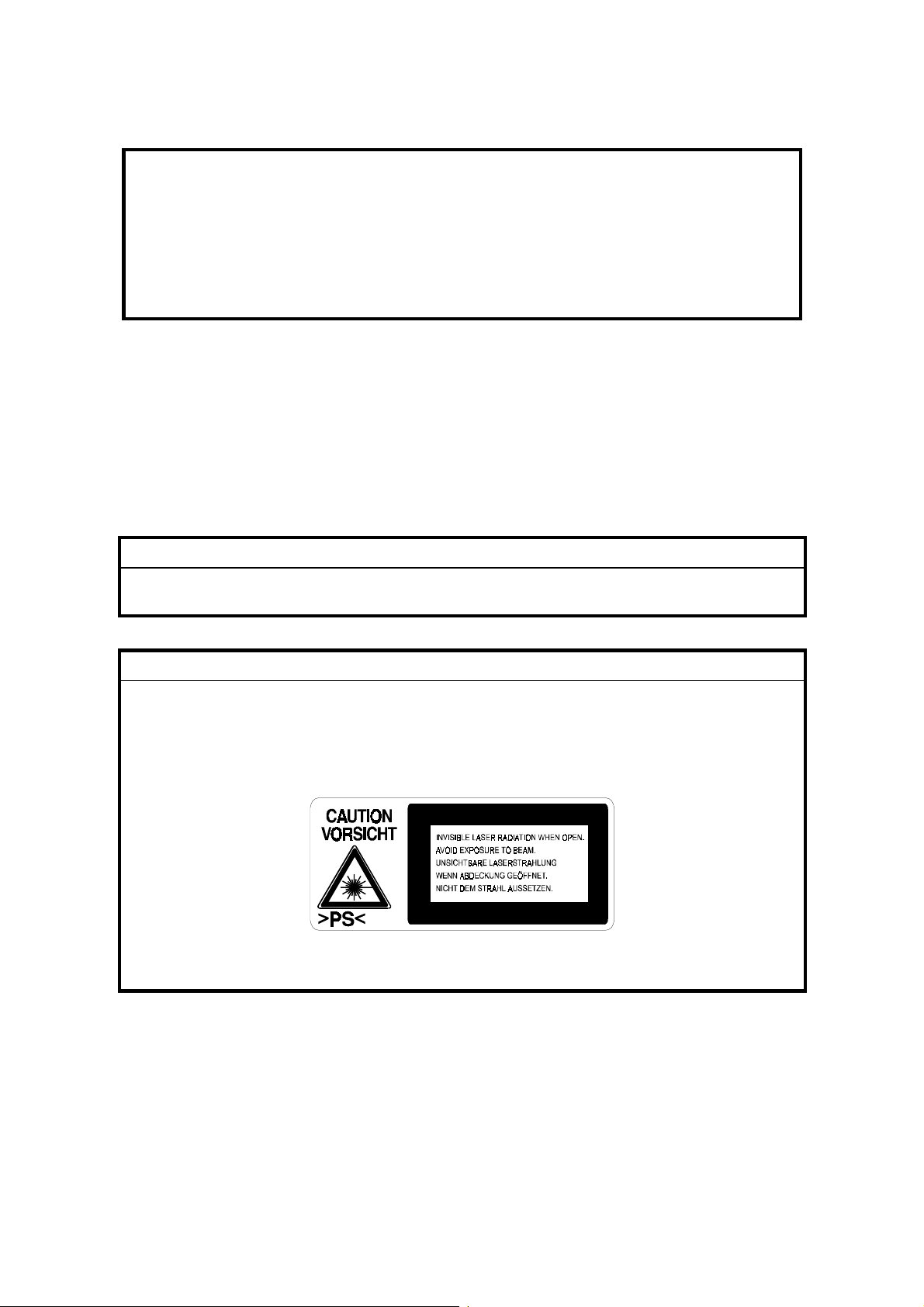
LASER SAFETY
The Center for Devices and Radiological Health (CDRH) prohibits the repair of
laser-based optical units in the field. The optical housing unit can only be repaired
in a factory or at a location with the requisite equipment. The laser subsystem is
replaceable in the field by a qualified Customer Engineer. The laser chassis is not
repairable in the field. Customer engineers are therefore directed to return all
chassis and laser subsystems to the factory or service depot when replacement of
the optical subsystem is required.
!
WARNING
Use of controls, or adjustment, or performance of procedures other than
those specified in this manual may result in hazardous radiation exposure.
!
WARNING
WARNING: Turn off the main switch before attempting any of the
procedures in the Laser Unit section. Laser beams can seriously damage
your eyes.
CAUTION MARKING:
G058R500.WMF
Page 15

Trademarks
Microsoft®, Windows®, and MS-DOS® are registered trademarks of Microsoft
Corporation in the United States and other countries.
PostScript® is a registered trademark of Adobe Systems, Incorporated.
PCL® is a registered trademark of Hewlett-Packard Company.
Ethernet® is a registered trademark of Xerox Corporation.
PowerPC® is a registered trademark of International Business Machines
Corporation.
Other product names used herein are for identification purposes only and may be
trademarks of their respective companies. We disclaim any and all rights involved
with those marks.
Page 16

Page 17

G056/G058
TABLE OF CONTENTS
INSTALLATION
1. INSTALLATION .......................................................................... 1-1
1.1 INSTALLATION REQUIREMENTS ...........................................................1-1
1.1.1 ENVIRONMENT ...............................................................................1-1
1.1.2 MACHINE LEVEL.............................................................................1-1
1.1.3 MACHINE SPACE REQUIREMENT.................................................1-1
1.1.4 POWER REQUIREMENTS ..............................................................1-2
1.2 MACHINE INSTALLATION .......................................................................1-2
1.3 OPTIONAL UNIT INSTALLATION.............................................................1-2
PREVENTIVE MAINTENANCE
2. PREVENTIVE MAINTENANCE................................................... 2-1
2.1 USER MAINTENANCE .............................................................................2-1
2.2 SERVICE MAINTENANCE........................................................................2-2
REPLACEMENT AND ADJUSTMENT
3. REPLACEMENT AND ADJUSTMENT........................................ 3-1
3.1 SPECIAL TOOLS ......................................................................................3-1
3.2 EXTERIOR COVERS ................................................................................3-2
3.3 LASER UNIT .............................................................................................3-3
3.3.1 CAUTION DECAL LOCATIONS.......................................................3-3
3.3.2 POLYGON MIRROR MOTOR ..........................................................3-4
3.3.3 LASER SYNCHRONIZATION DETECTOR......................................3-4
3.3.4 LASER UNIT ....................................................................................3-5
3.3.5 LASER DIODE UNIT ........................................................................3-7
Laser beam pitch adjustment................................................................3-8
3.4 TRANSFER ROLLER................................................................................3-9
3.5 TONER END SENSOR .............................................................................3-9
3.6 FUSING...................................................................................................3-10
3.6.1 FUSING UNIT.................................................................................3-10
3.6.2 HOT ROLLER AND FUSING LAMP...............................................3-11
3.6.3 THERMISTOR AND THERMOSTAT..............................................3-13
3.7 PAPER FEED..........................................................................................3-14
3.7.1 FEED ROLLER...............................................................................3-14
3.7.2 FRICTION PAD ..............................................................................3-14
3.8 BY-PASS TRAY ......................................................................................3-15
3.8.1 BY-PASS TRAY UNIT AND BY-PASS FEED ROLLER .................3-15
3.9 PRINTER CONTROLLER BOARD..........................................................3-16
3.10 ENGINE BOARD...................................................................................3-16
SM i G056/G058/G073/G074
Page 18

3.11 MAIN MOTOR .......................................................................................3-17
3.12 SOLENOIDS AND CLUTCHES.............................................................3-17
3.13 POWER SUPPLY UNIT AND HIGH VOLTAGE SUPPLY BOARD .......3-18
3.14 IMAGE ADJUSTMENT..........................................................................3-19
3.14.1 REGISTRATION ADJUSTMENT..................................................3-19
3.14.2 PARALLELOGRAM IMAGE ADJUSTMENT ................................3-19
TROUBLESHOOTING
4. TROUBLESHOOTING ................................................................ 4-1
4.1 SERVICE CALL CONDITIONS .................................................................4-1
4.1.1 SUMMARY .......................................................................................4-1
4.1.2 SC CODE DESCRIPTIONS .............................................................4-2
4.2 CONTROLLER ERROR ............................................................................4-4
4.3 ELECTRICAL COMPONENT DEFECTS ..................................................4-6
4.3.1 SENSORS ........................................................................................4-6
4.3.2 SWITCHES.......................................................................................4-6
4.4 BLOWN FUSE CONDITIONS ...................................................................4-7
4.5 LEDS .........................................................................................................4-7
SERVICE TABLES
5. SERVICE TABLES...................................................................... 5-1
5.1 SERVICE PROGRAM MODE....................................................................5-1
5.1.1 ENABLING AND DISABLING SERVICE PROGRAM MODE...........5-1
Entering the Service Mode....................................................................5-1
Accessing the Required Program .........................................................5-1
Inputting a Value or Setting for a Service Program...............................5-2
Exiting Service Mode ............................................................................5-2
5.2 PRINTER CONTROLLER SERVICE MODE.............................................5-3
5.2.1 SERVICE MODE MENU (‘1. SERVICE MENU’)..............................5-3
5.2.2 BIT SWITCH PROGRAMMING ........................................................5-3
5.3 PRINTER ENGINE SERVICE MODE........................................................5-4
5.3.1 SERVICE MODE TABLE (‘2. ENGINE MAINTE’)............................5-4
Memory Clear .......................................................................................5-8
5.3.2 INPUT CHECK TABLE...................................................................5-10
Table 1: Paper Size Switch (Main Unit) ..............................................5-11
Table 2: Paper Size Switch (optional paper tray)................................5-12
Table 3: Paper Height Sensor (standard cassette).............................5-12
Table 4: Paper Height Sensor (optional paper tray)............................5-12
5.3.3 OUTPUT CHECK TABLE...............................................................5-13
5.4 FIRMWARE UPDATE PROCEDURE......................................................5-14
5.4.1 CONTROLLER/NIB/ENGINE FIRMWARE UPDATE......................5-14
5.4.2 ERROR RECOVERY......................................................................5-15
Controller ............................................................................................5-15
NIB/Engine Board ...............................................................................5-15
G056/G058/G073/G074 ii SM
Page 19

Rev. 12/2002
5.5 POWER-ON SELF TEST ........................................................................5-16
5.6 OTHER TESTS .......................................................................................5-16
5.7 USER PROGRAM MODE ....................................................................... 5-17
5.8 DIP SWITCHES.......................................................................................5-18
Controller Board.................................................................................. 5-18
Engine Board ......................................................................................5-18
5.9 FIRMWARE HISTORY ............................................................................5-19
5.9.1 G056/G058 ENGINE FIRMWARE MODIFICATION HISTORY ......5-19
5.9.2 G056/G058 NIB FIRMWARE MODIFICATION HISTORY..............5-20
5.9.3 G056/G058 CONTROLLER FIRMWARE HISTORY ......................5-23
DETAILED DESCRIPTIONS
6. DETAILED SECTION DESCRIPTIONS ....................................... 6-1
6.1 OVERVIEW ...............................................................................................6-1
6.1.1 MECHANICAL COMPONENT LAYOUT...........................................6-1
6.1.2 PAPER PATH...................................................................................6-2
6.2 BOARD STRUCTURE............................................................................... 6-3
6.2.1 OVERVIEW ......................................................................................6-3
6.2.2 DESCRIPTIONS............................................................................... 6-4
6.2.3 CONTROLLER BOARD ...................................................................6-5
6.3 PRINTING PROCESS...............................................................................6-6
6.3.1 OVERVIEW ......................................................................................6-6
6.3.2 LASER EXPOSURE .........................................................................6-7
Overview...............................................................................................6-7
Automatic Power Control (APC) ...........................................................6-8
LD Safety Mechanisms .........................................................................6-9
6.3.3 CARTRIDGE OVERVIEW .............................................................. 6-10
6.3.4 DRUM CHARGE.............................................................................6-10
6.3.5 DEVELOPMENT.............................................................................6-11
Overview.............................................................................................6-11
Toner Supply ......................................................................................6-11
Development Unit ...............................................................................6-11
Toner Density Control .........................................................................6-12
Development Bias...............................................................................6-12
Toner End Detection ...........................................................................6-13
6.3.6 IMAGE TRANSFER AND PAPER SEPARATION ..........................6-14
Overview.............................................................................................6-14
Transfer Roller Cleaning .....................................................................6-14
6.3.7 CLEANING ..................................................................................... 6-15
6.3.8 QUENCHING..................................................................................6-15
6.3.9 ID CHIP ..........................................................................................6-16
6.4 PAPER FEED..........................................................................................6-17
6.4.1 OVERVIEW .................................................................................... 6-17
Paper Tray ..........................................................................................6-17
By-pass Tray.......................................................................................6-17
6.4.2 PAPER TRAY.................................................................................6-18
Tray Extension....................................................................................6-18
SM iii G056/G058/G073/G074
Page 20

Paper Lift ............................................................................................6-18
Paper Feed and Registration..............................................................6-19
Paper Size Detection ..........................................................................6-20
Paper End/Paper Near-end Detection ................................................6-20
6.4.3 BY-PASS TRAY..............................................................................6-21
6.5 IMAGE FUSING AND PAPER EXIT........................................................6-22
6.5.1 OVERVIEW ....................................................................................6-22
6.5.2 FUSING DRIVE ..............................................................................6-22
6.5.3 FUSING ENTRANCE GUIDE SHIFT..............................................6-23
6.5.4 PRESSURE ROLLER.....................................................................6-23
6.5.5 NEW FUSING UNIT DETECTION..................................................6-24
6.5.6 FUSING TEMPERATURE CONTROL............................................6-25
6.5.7 PAPER EXIT ..................................................................................6-26
6.5.8 ENERGY SAVER MODE................................................................6-27
Entering Energy Saver Mode..............................................................6-27
Leaving Energy Saver Mode...............................................................6-27
6.6 CONTROLLER FUNCTIONS ..................................................................6-28
6.6.1 METER-CHARGE MODE...............................................................6-28
Meter-charge Counter Display ............................................................6-28
PM Warning Display ...........................................................................6-28
6.6.2 SAMPLE PRINT .............................................................................6-28
6.6.3 LOCKED PRINT .............................................................................6-29
6.6.4 PAPER SOURCE SELECTION......................................................6-29
Tray Priority (Auto Tray Select)...........................................................6-29
Tray Lock............................................................................................6-29
Manual Tray Select.............................................................................6-29
6.6.5 AUTO CONTINUE..........................................................................6-30
Auto Tray Select .................................................................................6-30
Manual Tray Select.............................................................................6-30
6.6.6 PAPER OUTPUT TRAY .................................................................6-31
Output Tray Selected..........................................................................6-31
Auto Tray Switching............................................................................6-31
6.7 NIB ..........................................................................................................6-32
6.7.1 BLOCK DIAGRAM..........................................................................6-32
6.7.2 LED INDICATORS..........................................................................6-32
6.8 IEEE1394 INTERFACE...........................................................................6-33
6.8.1 SPECIFICATIONS..........................................................................6-33
Hardware Specification.......................................................................6-33
System Requirements.........................................................................6-33
6.8.2 IEEE1394 .......................................................................................6-33
6.8.3 BLOCK DIAGRAM..........................................................................6-34
6.8.4 PIN ASSIGNMENT.........................................................................6-34
6.8.5 REMARKS ABOUT THIS INTERFACE KIT....................................6-35
6.8.6 TROUBLESHOOTING NOTES ......................................................6-35
G056/G058/G073/G074 iv SM
Page 21

SPECIFICATIONS
7. SPECIFICATIONS....................................................................... 7-1
7.1. GENERAL SPECIFICATIONS..................................................................7-1
7.1.1 SUPPORTED PAPER SIZES...........................................................7-3
7.2. SOFTWARE ACCESSORIES ..................................................................7-4
7.2.1 PRINTER DRIVERS.........................................................................7-4
7.2.2 UTILITY SOFTWARE.......................................................................7-4
7.3. MACHINE CONFIGURATION..................................................................7-5
7.3.1 SYSTEM COMPONENTS ................................................................7-5
7.4. OPTIONAL EQUIPMENT.........................................................................7-6
7.4.1 PAPER TRAY UNIT..........................................................................7-6
7.4.2 ENVELOPE FEEDER.......................................................................7-6
7.4.3 DUPLEX UNIT..................................................................................7-6
7.4.4 FOUR-BIN MAILBOX .......................................................................7-7
7.4.5 ONE-BIN SHIFT TRAY.....................................................................7-7
PAPER TRAY UNIT G555/ENVELOPE FEEDER G556
1. REPLACEMENT AND ADJUSTMENT........................................ 8-1
1.1 PAPER FEED UNIT ..................................................................................8-1
1.2 PAPER FEED ROLLER ............................................................................8-2
1.3 FRICTION PAD .........................................................................................8-2
2. DETAILED DESCRIPTIONS ....................................................... 8-3
2.1 OVERALL MACHINE INFORMATION ......................................................8-3
2.1.1 MECHANICAL COMPONENT LAYOUT...........................................8-3
2.1.2 ELECTRICAL COMPONENT LAYOUT............................................8-3
2.2 DETAILED SECTION DESCRIPTIONS ....................................................8-4
2.2.1 PAPER FEED AND SEPARATION ..................................................8-4
2.2.2 PAPER LIFT.....................................................................................8-5
2.2.3 PAPER END DETECTION ...............................................................8-5
2.2.4 PAPER HEIGHT DETECTION .........................................................8-6
2.2.5 PAPER SIZE DETECTION...............................................................8-7
3. ENVELOPE FEEDER.................................................................. 8-8
3.1 OVERALL MACHINE INFORMATION ......................................................8-8
3.1.1 MECHANICAL COMPONENT LAYOUT...........................................8-8
DUPLEX UNIT G552
1. REPLACEMENT AND ADJUSTMENT........................................ 9-1
1.1 EXTERIOR COVERS ................................................................................9-1
1.2 DUPLEX BOARD AND SENSORS ...........................................................9-2
SM v G056/G058/G073/G074
Page 22

2. DETAILED DESCRIPTION ......................................................... 9-3
2.1 OVERALL MACHINE INFORMATION ......................................................9-3
2.1.1 MECHANICAL COMPONENT LAYOUT...........................................9-3
2.1.2 DRIVE LAYOUT ...............................................................................9-4
2.1.3 ELECTRICAL COMPONENT LAYOUT............................................9-4
2.2 DETAILED SECTION DESCRIPTIONS ....................................................9-5
2.2.1 BASIC OPERATION.........................................................................9-5
Longer than A4 LEF/LT LEF.................................................................9-5
Length up to A4 LEF/LT LEF ................................................................9-6
2.2.2 FEED IN AND EXIT MECHANISM ...................................................9-7
Feeding paper into the duplex unit:.......................................................9-7
Inversion and exit:.................................................................................9-7
FOUR-BIN MAILBOX G553
1. REPLACEMENT AND ADJUSTMENT...................................... 10-1
1.1 EXTERIOR COVERS ..............................................................................10-1
1.2 OVERFLOW AND VERTICAL TRANSPORT SENSORS .......................10-2
1.3 MAIN MOTOR .........................................................................................10-3
2. DETAILED DESCRIPTIONS ..................................................... 10-5
2.1 OVERALL MACHINE INFORMATION ....................................................10-5
2.1.1 MECHANICAL COMPONENT LAYOUT.........................................10-5
2.1.2 DRIVE LAYOUT .............................................................................10-6
2.1.3 ELECTRICAL COMPONENT LAYOUT..........................................10-7
2.2 DETAILED SECTION DESCRIPTIONS ..................................................10-8
2.2.1 BASIC OPERATION.......................................................................10-8
ONE-BIN SHIFT TRAY G554
1. REPLACEMENT AND ADJUSTMENT...................................... 11-1
1.1 EXTERIOR COVERS ..............................................................................11-1
1.2 SHIFT TIMING AND TRAY PAPER SENSORS......................................11-2
1.3 COVER AND OVERFLOW SENSORS ...................................................11-2
1.4 MAIN MOTOR .........................................................................................11-3
2. DETAILED DESCRIPTIONS ..................................................... 11-5
2.1 OVERALL MACHINE INFORMATION ....................................................11-5
2.1.1 MECHANICAL COMPONENT LAYOUT.........................................11-5
2.1.2 DRIVE LAYOUT .............................................................................11-5
2.1.3 ELECTRICAL COMPONENT LAYOUT..........................................11-6
2.2 DETAILED SECTION DESCRIPTIONS ..................................................11-7
2.2.1 BASIC OPERATION.......................................................................11-7
2.2.2 SORT MODE OPERATION............................................................11-7
G056/G058/G073/G074 vi SM
Page 23

SWAPBOX
AND SWAPFTL
INSTALLATION MANUAL
1. INTRODUCTION ...................................................................... 12-1
1.1 PRECAUTIONS........................................................................................12-1
1.1.1 SWAPBOX AND SOFTWARE ........................................................12-1
1.1.2 SOFTWARE LICENSE AGREEMENT ...........................................12-1
1.2 SYSTEM REQUIREMENTS ....................................................................12-1
1.3 ITEMS TO PREPARE BEFORE INSTALLATION ...................................12-1
1.4 WINDOWS 95 VERSION CONFIRMATION ............................................12-2
2. SWAPBOX INSTALLATION ..................................................... 12-4
2.2 DRIVER INSTALLATION ........................................................................12-4
3. SOFTWARE (SWAPFTL) INSTALLATION ............................... 12-5
3.1 SWAPFTL SOFTWARE INSTALLATION ................................................12-5
3.2 VERIFICATION ...................................................................................... 12-5
3.2.1 SOFTWARE VERSION ..................................................................12-5
3.2.2 FLASH MEMORY CARD AUTOMATIC DETECTION ....................12-6
4. TROUBLESHOOTING ............................................................... 12-7
4.1 SWAPBOX RESOURCE CONFLICT ......................................................12-7
4.11 IRQ AND I/O ADDRESS ..................................................................12-7
4.1.2 MEMORY ADDRESS ......................................................................12-7
4.2 FAILED TO OPEN PCCARD ERRORS ...................................................12-8
4.2.1 TIMELAG TO LOADING DRIVER ...................................................12-8
4.2.3 RESOURCE CONFLICT .................................................................12-8
4.3 INVALID DYNAMIC LINK CALL FROM SWAPENUM ERROR...............12-9
4.4 SWAPFTL PROBLEM WITH NOTEBOOK COMPUTERS.......................12-9
4.4.1 WINDOWS AND PC CARD DRIVER VERSION .............................12-9
4.4.2 SYSTEM SUMMERY.......................................................................12-9
4.5 COMPLETE UNINSTALL .......................................................................12-10
SWAPFTL
BINARY UTILITY OPERATION MANUAL
1. OVERVIEW ................................................................................ 13-1
2. OPERATION .............................................................................. 13-2
2.1 PROGRAMMING A FLASH MEMORY CARD..........................................13-2
2.1.1 GETTING A SOURCE FILE ............................................................13-2
2.1.2 PROGRAMMING A CARD WITH THE SOURCE............................13-2
2.2 DOWNLOADING TO A MACHINE ...........................................................13-4
2.3 SAVING DATA TO A FILE .......................................................................13-4
3. FUNCTIONS............................................................................... 13-5
3.1 FILE MENU ..............................................................................................13-5
3.1.1 FILE – OPEN...................................................................................13-5
SM vii G056/G058/G073/G074
Page 24

3.1.2 FILE – CLOSE.................................................................................13-5
3.1.3 FILE – SAVE ...................................................................................13-5
3.14 FILE – SAVE AS...............................................................................13-6
3.2 VIEW MENU.............................................................................................13-6
3.2.1 VIEW – TOOLBAR ..........................................................................13-6
3.2.2 VIEW – STATUS BAR.....................................................................13-6
3.3 IMAGE MENU ..........................................................................................13-7
3.3.1 IMAGE – ERASE.............................................................................13-7
3.3.2 IMAGE – READ ...............................................................................13-8
3.3.3 IMAGE – WRITE .............................................................................13-9
3.3.4 IMAGE – VERIFICATION..............................................................13-10
3.4 HELP MUNU ..........................................................................................13-11
3.4.1 HELP – ABOUT SWAPUTI............................................................13-11
G056/G058/G073/G074 viii SM
Page 25

Rev. 12/2002
G073/G074
TABLE OF CONTENTS
INSTALLATION
1. INSTALLATION............................................................................ 1-1
1.1 OPTIONAL UNIT INSTALLATION.............................................................1-1
PREVENTIVE MAINTENANCE
2. PREVENTIVE MAINTENANCE.................................................... 2-1
2.1 USER/SERVICE MAINTENANCE.............................................................2-1
REPLACEMENT AND ADJUSTMENT
3. REPLACEMENT AND ADJUSTMENT ........................................ 3-1
3.1 DIFFERENCES FROM THE MODEL K-P1 ...............................................3-1
TROUBLESHOOTING
4. TROUBLESHOOTING ................................................................. 4-1
4.1 SERVICE CALL CONDITIONS .................................................................4-1
4.1.1 SUMMARY .......................................................................................4-1
4.1.2 CONTROLLER SC CODE DESCRIPTIONS ....................................4-2
4.2 JAM LOCATIONS......................................................................................4-6
4.3 FIRMWARE HISTORY ..............................................................................4-7
4.3.1 PRINTER ENGINE FIRMWARE HISTORY......................................4-7
4.3.2 PRINTER CONTROLLER FIRMWARE HISTORY ...........................4-8
SERVICE TABLES
5. SP MODE TABLES ...................................................................... 5-1
5.1 PRINTER CONTROLLER SERVICE MODE .............................................5-1
5.1.1 SERVICE MODE MENU (“1. SERVICE MENU”) .........................5-1
5.1.2 BIT SWITCH PROGRAMMING ........................................................5-2
5.2 PRINTER ENGINE SERVICE MODE........................................................5-3
5.2.1 SERVICE MODE TABLE (“2. ENGINE MAINTE”) .......................5-3
5.2.2 INPUT / OUTPUT CHECK TABLE ...................................................5-8
5.3 USER PROGRAM MODE .........................................................................5-9
SM i G056/G058/G073/G074
Page 26

DETAILED DESCRIPTIONS
6. DETAILED SECTION DESCRIPTIONS ...................................... 6-1
6.1 CONTROLLER BOARD ............................................................................6-1
6.2 USB ...........................................................................................................6-2
6.2.1 SPECIFICATIONS............................................................................6-2
6.2.2 USB 1.1/2.0 ......................................................................................6-2
6.2.3 USB CONNECTORS........................................................................6-3
6.2.4 PIN ASSIGNMENT...........................................................................6-3
6.2.5 REMARKS........................................................................................6-4
Related SP Mode..................................................................................6-4
6.3 IEEE802.11B (WIRELESS LAN) ...............................................................6-5
6.3.1 SPECIFICATIONS............................................................................6-5
6.3.2 BLOCK DIAGRAM............................................................................6-5
6.3.3 TRANSMISSION MODE...................................................................6-6
Ad hoc Mode.........................................................................................6-6
Infrastructure Mode...............................................................................6-6
6.3.4 SECURITY FEATURES ...................................................................6-7
Using the SSID in Ad hoc mode............................................................6-7
6.3.5 TROUBLESHOOTING NOTES ........................................................6-8
Communication Status..........................................................................6-8
Channel Settings...................................................................................6-8
Troubleshooting Steps..........................................................................6-9
6.4 NEW FEATURES ....................................................................................6-10
6.4.1 IP OVER 1394 ................................................................................6-10
6.4.2 JOB SPOOLING.............................................................................6-11
Description..........................................................................................6-11
Related SP Modes..............................................................................6-11
SPECIFICATIONS
7. SPECIFICATIONS
1. GENERAL SPECIFICATIONS.....................................................................7-1
1.1 SUPPORTED PAPER SIZES..............................................................7-3
2. SOFTWARE ACCESSORIES .....................................................................7-4
2.1 PRINTER DRIVERS ............................................................................7-4
2.2 UTILITY SOFTWARE..........................................................................7-4
3. MACHINE CONFIGURATION ......................................................................7-5
3.1 SYSTEM COMPONENTS ...................................................................7-5
3.2 INTERNAL OPTIONS..........................................................................7-6
4. OPTIONAL EQUIPMENT .............................................................................7-7
G056/G058/G073/G074 ii SM
Page 27
INSTALLATION B056/B058
DUPLEX UNIT G552
INSTALLATION G073/G074
PREVENTIVE MAINTENANCE B056/B058
FOUR-BIN MAILBOX G553
PREVENTIVE MAINTENANCE
G073/G074
REPLACEMENT AND ADJUSTMENT B056/B058
ONE-BIN SHIFT TRAY G554
REPLACEMENT AND ADJUSTMENT
G073/G074T
TROUBLESHOOTING B056/B058
SWAPBOX
TM
AND SWAPFTL
TROUBLESHOOTING G073/G074
TM
INSTALLATION MANUAL
TAB
POSITION 1
TAB
POSITION 2
TAB
POSITION 3
TAB
POSITION 4
SERVICE TABLES B056/B058
SWAPFTLTM BINARY UTILITY OPERATION MANUAL
SERVICE TABLES G073/G074
DETAILED DESCRIPTIONS B056/B058
DETAILED DESCRIPTIONS G073/G074
SPECIFICATIONS B056/B058
SPECIFICATIONS G073/G074
PAPER TRAY G555/ENVELOPE FEEDER G556
TAB
POSITION 5
TAB
POSITION 6
TAB
POSITION 7
TAB
POSITION 8
Page 28

Page 29

INSTALLATION
Page 30

Page 31

INSTALLATION REQUIREMENTS
1. INSTALLATION
1.1 INSTALLATION REQUIREMENTS
1.1.1 ENVIRONMENT
1. Temperature Range: 10 °C to 32 °C (50 °F to 89.6 °F)
2. Humidity Range: 15 % to 80 % RH
3. Ambient Illumination: Less than 2,000 lux (do not expose to direct sunlight).
4. Ventilation: 3 times/hr/person
5. Avoid areas which are exposed to sudden temperature changes. This includes:
1) Areas directly exposed to cool air from an air conditioner.
2) Areas directly exposed to heat from a heater.
6. Do not place the machine in an area where it will be exposed to corrosive
gases.
7. Do not install the machine at any location over 2,500 m (8,125 ft.) above sea
level.
8. Place the machine on a strong and level base. (Inclination on any side should
be no more than 5 mm.)
9. Do not place the machine where it may be subjected to strong vibrations.
Installation
1.1.2 MACHINE LEVEL
Front to back: Within 5 mm (0.2”) of level
Right to left: Within 5 mm (0.2”) of level
1.1.3 MACHINE SPACE REQUIREMENT
Place the machine near the power source, providing clearance as shown.
A: Over 10 cm (4”)
B: Over 10 cm (4”)
C: Over 100 cm (40”)
D: Over 10 cm (4”)
A
B
D
C
G056I500.WMF
SM 1-1 G056/G058
Page 32

MACHINE INSTALLATION
1.1.4 POWER REQUIREMENTS
!
CAUTION
1. Make sure the plug is firmly inserted in the outlet.
2. Avoid multi-wiring.
3. Be sure to ground the machine.
1. Input voltage level: 120 V, 60 Hz: More than 10 A
220 V ~ 240 V, 50 Hz/60 Hz: More than 6 A
2. Permissible voltage fluctuation: ±10 %
3. Do not set anything on the power cord.
1.2 MACHINE INSTALLATION
Refer to the Operating Instructions for details.
1.3 OPTIONAL UNIT INSTALLATION
The following options are available for this machine. Refer to the Operating
Instructions for how to install these options.
• Paper Tray Unit
• 4-bin Mailbox
• 1-bin Shift Tray
• Duplex Unit
• Envelope Feeder
• NIB (G056 only) - the NIB is a standard component for the G058
• Hard disk
• IEEE1394 (G056/G058 - to install in the G058, the NIB must be removed first)
• 64-MB DIMM
G056/G058 1-2 SM
Page 33

PREVENTIVE MAINTENANCE
Page 34

Page 35

USER MAINTENANCE
2. PREVENTIVE MAINTENANCE
2.1 USER MAINTENANCE
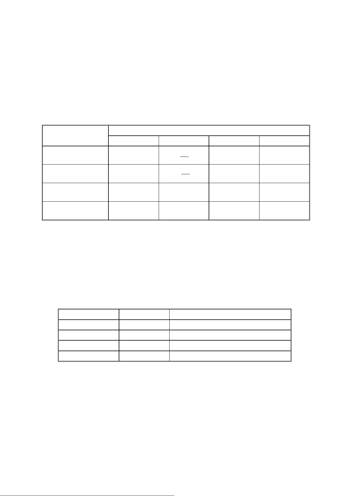
All PM items can be done by the customer, using the maintenance kit. The
maintenance kit contains the items listed below.
Meter-charge mode must be set to 'disabled' (controller service mode).
Cross-reference: Section 5.3 Engine service mode
When the PM counter reaches 90K, "Replace Maintenance Kit" is displayed. After
the user replaces the fusing unit in the maintenance kit, the machine automatically
resets the PM counter.
Item Quantity Remarks
Fusing unit 1
Transfer roller 1
Paper feed roller for the standard tray 1
Paper feed rollers for the optional
PFU
Friction pad - standard tray 1
Friction pads - optional trays 2 Optional paper tray unit
2
Optional paper tray unit
Preventive
Maintenance
SM 2-1 G056/G058
Page 36

SERVICE MAINTENANCE
2.2 SERVICE MAINTENANCE
The following tables list the PM items when the PM is done by service.
NOTE: 1) You must switch on meter-charge mode in printer engine service mode
to disable the user's PM warning.
2) After replacing the fusing unit, make sure to reset the PM counter using
the printer engine service mode “PM Counter Reset”.
Symbol key: C: Clean, R: Replace, L: Lubricate, I: Inspect
Main unit
Item 90K EM Remarks
Paper Feed
Paper Feed Roller R C Clean with water
Friction Pad R C Clean with water
Registration Mylar C C Clean with water
Around the Drum
Transfer Roller R
Fusing Unit and Paper Exit
Hot Roller R
Pressure Roller R
Hot Roller Strippers R
Fusing Thermistor R C Clean with alcohol if necessary.
Bushing - Fusing Roller R
Bushing - Fusing Pressure R
Fusing Entrance and Exit Guide
Plates
C
Clean with water or alcohol
Paper Tray Unit
90K EM NOTE
Paper Feed Roller R C Clean with water
Friction Pad R C Dry cloth
Bottom Plate Pad C C Clean with water
Four-bin Mailbox
90K EM NOTE
Exit Rollers C Clean with water
Driven Rollers C Clean with water
Trays C Clean with water
One-bin Shift Tray
90K EM NOTE
Exit Rollers C Clean with water
Driven Rollers C Clean with water
Transport Rollers C Clean with water
Paper Tray C Clean with water
Tray Paper Sensor C Clean with water
G056/G058 2-2 SM
Page 37

REPLACEMENT AND ADJUSTMENT
Page 38

Page 39

SPECIAL TOOLS
3. REPLACEMENT AND ADJUSTMENT
!
CAUTION
Turn off the main power switch and unplug the machine before attempting
any of the procedures in this section.
NOTE: This manual uses the following symbols.
☛ : See or Refer to ! : Screws " : Connector
3.1 SPECIAL TOOLS
Part Number Description
A0069104 Scanner Positioning Pin (4 pcs/set) 3.3 1
A2309352 Flash Memory Card - 4MB 5.4 1
G0219350 Loop-back connector - parallel 5.5 1
Described
Section
Q’ty
Replacement
and
Adjustment
SM 3-1 G056/G058
Page 40

EXTERIOR COVERS
3.2 EXTERIOR COVERS
[A]
[D]
[B]
[C]
[E]
G058R701.WMF
G058R201.WMF
[H]
[F]
[G]
G058R703.WMF
G058R702.WMF
To remove the left or right cover, separate the machine from the optional paper
tray unit first.
Open the front cover.
[A]: Remove paper tray
[B]: Operation panel (2 hooks, " x1)
[C]: Upper exit cover
[D]: Open the exit guide plate.
[E]: Upper cover (! x4)
[F]: By-pass tray unit (2 hooks)
[G]: Front cover (3 hooks, " x1)
[H]: Left cover (! x2)
[I]: Right cover (3 hooks)
G056/G058 3-2 SM
Page 41

LASER UNIT
3.3 LASER UNIT
!
WARNING
Turn off the main power switch and unplug the machine before attempting
any of the procedures in this section. Laser beams can seriously damage
your eyes.
3.3.1 CAUTION DECAL LOCATIONS
The caution decal is located in the laser section as shown below.
Replacement
and
Adjustment
G058R500.WMF
G058R202.WMF
SM 3-3 G056/G058
Page 42

LASER UNIT
3.3.2 POLYGON MIRROR MOTOR
!
WARNING
Turn off the main switch and unplug the machine before attempting any of
the procedures in this section. Laser beams can seriously damage your
eyes.
Operation panel (☛ 3.2 Exterior
Covers)
[A]
Upper cover (☛ 3.2 Exterior Covers)
[A]: Polygon mirror cover (! x2)
[B]: Polygon mirror motor
(! x4, " x1)
NOTE: Do not touch the surface of the
mirror with bare hands.
3.3.3 LASER SYNCHRONIZATION DETECTOR
Operation panel (☛ 3.2 Exterior Covers)
[B]
G058R204.WMF
Upper cover (☛ 3.2 Exterior Covers)
[A]: Laser synchronization detector (" x1)
[A]
G058R206.WMF
G056/G058 3-4 SM
Page 43

3.3.4 LASER UNIT
[A]
G058R730.WMF
LASER UNIT
[D]
Replacement
and
Adjustment
[C]
Operation panel (☛ 3.2 Exterior Covers)
Upper cover (☛ 3.2 Exterior Covers)
Left cover (☛ 3.2 Exterior Covers)
[A]: 230V machine only: Sheet (! x1)
[B]: Thermistor (! x1)
[C]: Clip
[D]: Laser unit (! x4, 1 flat cable, " x2)
[B]
G058R203.WMF
SM 3-5 G056/G058
Page 44

LASER UNIT
When reinstalling the laser unit
Use the scanner positioning pin (P/N: A0069104) to reinstall the unit.
[E]
G058R208.WMF
[E]: Set the positioning pins as shown above. Then secure the laser unit.
G056/G058 3-6 SM
Page 45

Rev. 08/2001
3.3.5 LASER DIODE UNIT
⇒
[F]
[D]
[C]
[A]
[B]
LASER UNIT
Replacement
and
Adjustment
[E]
G058R209.WMF
Laser Unit (☛ 3.3.4 Laser Unit)
[A]: Spring
[B]: LD unit holders
[C]: Loosen the screw
[D]: Nut
[E]: LD Unit
NOTE: 1) Do not remove the screws that secure the LD board.
2) Do not touch any variable resistors on the LD board.
When installing the LD Unit:
Tighten the screw [C] until the unpainted portion of the screw [F] is not visible.
After installing the LD unit, check the test pattern for the final adjustment (see
Laser beam pitch adjustment the following procedure).
SM 3-7 G056/G058
Page 46

LASER UNIT
Laser beam pitch adjustment
1. Print out the following test patterns – cross-stitch pattern and grid pattern.
2. Check these test patterns. If the laser beam pitch is not correct, the images are
as follows.
• Cross-stitch pattern: Vertical black strips seem to appear.
• Grid pattern: The density of the diagonal lines is light or the lines have
disappeared.
3. Adjust the LD unit holder position: Tighten or loosen the screw [C] (see the
previous page) until the printout appears as follows.
• Cross-stitch pattern: The thin lines are of uniform thickness (no striping
effect should appear on the printout).
• Grid pattern: The diagonal lines appear clearly and are of normal density.
Feed direction
G056R502.WMF
Adjustment not complete Adjustment complete
G056/G058 3-8 SM
Page 47

3.4 TRANSFER ROLLER
Cartridge
[A]: Transfer roller
NOTE: Do not touch the transfer
roller surface.
TRANSFER ROLLER
3.5 TONER END SENSOR
Cartridge
[A]: Toner end sensor (4 hooks, " x1)
[A]
G058R401.WMF
Replacement
and
Adjustment
[A]
SM 3-9 G056/G058
G058R301.WMF
Page 48

FUSING
3.6 FUSING
3.6.1 FUSING UNIT
!
CAUTION
Allow time for the unit to cool before doing the following procedure.
[A]
[A]: Exit cover
[B]: Fusing unit (lift hooks [C])
G058R501.WMF
[C]
[C]
[B]
G058R502.WMF
G056/G058 3-10 SM
Page 49

3.6.2 HOT ROLLER AND FUSING LAMP
[A]
[B]
FUSING
[D]
Fusing unit (☛ 3.6.1 Fusing Unit)
[A]: Right cover (! x2)
[B]: Upper fusing unit assembly (! x4)
[C]: Left cover (! x1)
[D]: Lamp holders (! x1 each)
G058R508.WMF
[D]
[C]
G058R507.WMF
Replacement
and
Adjustment
SM 3-11 G056/G058
Page 50

FUSING
[E]
G058R506.WMF
[H]
[G]
G058R505.WMF
[E]: Fusing lamp (! x2)
NOTE: The shorter cable must be at the hot roller gear side.
[F]: Guide plate (3 hooks)
[G]: Hot roller strippers (1 spring each)
[H]: Hot roller (2 C-rings, 1 gear, 2 bushings).
NOTE: Before installing the new hot roller, peel off 3 cm (1 inch) from both
ends of the protective sheet on the new roller.
Remove protective sheet.
[F]
G058R510.WMF
G056/G058 3-12 SM
Page 51

3.6.3 THERMISTOR AND THERMOSTAT
[A]
[B]
[E]
[C]
[D]
G058R503.WMF
FUSING
Replacement
and
Adjustment
Hot roller (☛ 3.6.2 Hot Roller and Fusing Lamp)
[A]: Wire cover (! x1)
[B]: Grounding plate (! x1, 1 wire)
[C]: Fusing unit connector (! x3, " x1))
[D]: Thermistor (! x1)
[E]: Thermostat (! x1)
SM 3-13 G056/G058
Page 52

PAPER FEED
3.7 PAPER FEED
3.7.1 FEED ROLLER
Paper Tray
[A]: Paper feed roller
3.7.2 FRICTION PAD
Paper Tray
[A]: Friction pad (2 hooks, 1 spring)
[A]
[A]
G058R107.WMF
G058R404.WMF
G056/G058 3-14 SM
Page 53

BY-PASS TRAY
3.8 BY-PASS TRAY
3.8.1 BY-PASS TRAY UNIT AND BY-PASS FEED ROLLER
[A]
[B]
G058R102.WMF
[C]
By-pass tray unit (☛ 3.2 Exterior Covers)
Front cover (☛ 3.2 Exterior Covers)
Cartridge
[A]: Paper guide (! x2)
[B]: Actuator
[C]: Gear (1 hook)
[D]: By-pass feed roller
When reinstalling the paper guide:
1) Set the paper guide on the bushing.
2) Install the left part of the actuator in the machine.
3) Install the right part of the actuator on the paper guide.
4) Install the paper guide.
5) Make sure that the actuator moves smoothly.
[D]
G058R103.WMF
Replacement
and
Adjustment
SM 3-15 G056/G058
Page 54

PRINTER CONTROLLER BOARD
3.9 PRINTER CONTROLLER BOARD
[A]: Printer controller board (! x2)
NOTE: Remove the NVRAM [B] from the old
printer controller board and put it on
the new board.
[A]
3.10 ENGINE BOARD
[B]
[C]
[A]
[D]
G058R710.WMF
G058R712.WMF
[B]
Left cover (☛ 3.2 Exterior Covers)
Printer controller board (☛ 3.9 Printer Controller Board)
[A]: Bracket (! x6, 1 grounding wire)
NOTE: The sheet is used for 230V machine only.
[B]: Clip
[C]: Engine board (! x5, all connectors)
NOTE: Remove the NVRAM [D] from the old engine board and put it on the
new board.
G056/G058 3-16 SM
Page 55

3.11 MAIN MOTOR
Left cover (☛ 3.2 Exterior Covers)
[A]: Main motor (! x4, " x1)
3.12 SOLENOIDS AND CLUTCHES
[A]
MAIN MOTOR
G058R711.WMF
Replacement
and
Adjustment
[F]
[C]
[D]
[E]
[A]
Left cover (☛ 3.2 Exterior Covers)
[A]: By-pass feed solenoid (! x1, " x1)
[B]: Gear (1 hook)
[C]: Stopper (! x1)
[D]: Relay clutch (1 hook, " x1)
[E]: Paper feed clutch (1 hook, " x1)
Main motor (☛ 3.11 Main Motor)
[F]: Registration clutch (# x1, " x1)
[B]
G058R714.WMF
SM 3-17 G056/G058
Page 56

POWER SUPPLY UNIT AND HIGH VOLTAGE SUPPLY BOARD
3.13 POWER SUPPLY UNIT AND HIGH VOLTAGE SUPPLY
BOARD
[A]
G058R707.WMF
[D]
[C]
[E]
G058R709.WMF
Left cover (☛ 3.2 Exterior Covers)
Fusing unit (☛ 3.6.1 Fusing Unit)
[A]: PSU cover (! x2)
[B]: PSU assembly (! x9, all connectors)
[C]: High voltage supply board (! x4)
[D]: 230V machine only: Choke coil (! x2, " x1)
[E]: Power supply unit (! x5)
[B]
G058R708.WMF
G056/G058 3-18 SM
Page 57

IMAGE ADJUSTMENT
3.14 IMAGE ADJUSTMENT
3.14.1 REGISTRATION ADJUSTMENT
The registration is adjusted using the user mode; “Maintenance-RegistrationAdjustment”
3.14.2 PARALLELOGRAM IMAGE ADJUSTMENT
NOTE: Use the scanner positioning pin (P/N: A0069104) for the adjustment.
Do the following procedure if a parallelogram is printed while adjusting the printing
registration using a trimming pattern.
Replacement
and
Adjustment
(a) (b)
G058R210.WMF
G056R500.WMF
1. Remove the upper cover (☛ 3.2 Exterior Covers)
2. Set a positioning pin to one of the hole (The above illustration explains when
the image (a) is printed out).
3. Loosen four screws and move the laser unit.
4. Tighten the laser unit.
5. Print the trimming area pattern to check the image. If it is still the same, repeat
step 3 to 5.
SM 3-19 G056/G058
Page 58

Page 59

TROUBLESHOOTING
Page 60

Page 61

SERVICE CALL CONDITIONS
4. TROUBLESHOOTING
4.1 SERVICE CALL CONDITIONS
4.1.1 SUMMARY
There are 2 levels of service call conditions.
Level Definition Reset Procedure
To prevent the machine from being
A
B
damaged, the SC can only be reset by a
service representative.
The machine cannot be operated at all.
The SC can be reset by turning the
operation switch off and on, if the SC was
caused by a sensor error.
NOTE: 1) If the problem concerns electrical circuit boards, first disconnect then
reconnect the connectors before replacing the PCBs.
2) If the problem concerns a motor lock, first check the mechanical load
before replacing motors or sensors.
Enter engine service mode
(Fusing Error Clear) and press
“#”.
Turn the main power switch off
and on.
Trouble-
shooting
SM 4-1 G056/G058
Page 62

SERVICE CALL CONDITIONS
4.1.2 SC CODE DESCRIPTIONS
Code No. Symptom Possible Cause
Charge roller current leak302 B
A charge roller current leak signal is
detected.
Polygon motor error320 B
The polygon motor does not reach its
operating speed within 10 seconds
after the polygon motor on signal, or
the lock signal is not detected for
more than a certain time during
operation.
• Cartridge (charge roller) defective
• High voltage supply board
defective
• Poor cartridge connection
• Polygon motor
• Polygon motor cable
1st laser synchronization error322 B
The laser synchronization detector
cannot detect the laser
synchronization signal for more than
5 consecutive 100 ms intervals.
LD drive current exceeded323 B
The LD driver detects this error for
more than 500 ms.
2nd laser synchronization error326 B
st
The 1
LD1 is already on, but the
laser synchronization detector cannot
detect the laser synchronization
signal from the 2
nd
LD for more than 5
consecutive 100 ms intervals.
Development bias leak391 B
A development bias leak signal is
detected.
Main motor lock500 B
A main motor lock signal is not
detected for more than 700 ms after
the main motor starts to rotate, or the
lock signal is not detected for more
than a certain time during rotation
after the last signal.
• Laser synchronization detector
board out of position
• Laser synchronization detector
board or cable defective
• Laser synchronization mirror out of
position
• LD unit defective
• Engine board defective
• LD unit defective
• Laser synchronization detector
board out of position
• LD unit defective
• Engine board defective
• High voltage supply board
defective
• Poor cartridge connection
• Main motor defective
• Too much load on the drive
mechanism
541 A
Unstable fusing temperature
During warm-up, the fusing
temperature rises by less than 20 °C
during 11 seconds.
The fusing temperature detected by
• Thermistor defective
• Fusing lamp open
• Fusing thermostat open
• Power supply board defective
• Poor connection of the fusing unit
the thermistor was 0 °C 5 seconds
after the fusing relay was turned on.
G056/G058 4-2 SM
Page 63

SERVICE CALL CONDITIONS
Code No. Symptom Possible Cause
Fusing temperature warm-up error542 A
The fusing temperature does not
reach more than 80 °C 17.5 seconds
after the main switch is turned on.
• Thermistor defective
• Fusing lamp open
• Fusing thermostat open
• Power supply board defective
• Poor connection of the fusing unit
543 A
Fusing overheat error
A fusing temperature of over 245 °C
• Fusing thermistor defective
• Power supply board defective
is detected for 1 second by the fusing
thermistor.
A fusing temperature of over 235 °C
is detected for 1 second after the
fusing lamp has been turned off.
Fusing lamp stays on545 A
The fusing lamp stays on more than
12 seconds after the main motor has
• Fusing thermistor defective
• Power supply board defective
• Poor connection of the fusing unit
been turned off.
546 A
Unstable fusing temperature
During standby, within 500 ms, the
fusing temperature goes below 60 °C
• Fusing thermistor defective
• Power supply board defective
• Poor connection of the fusing unit
twice or over 60 °C three times.
Within 1 minute, a 60 °C increase or
decrease in fusing temperature is
detected during five different onesecond intervals.
Zero cross signal malfunction547 B
Zero cross signals are not detected
• Power supply board defective
• Poor mains power supply condition
within 5 seconds.
Communication error - duplex unit610 B
The engine board cannot
communicate with the duplex unit.
• Poor connection between engine
board and duplex unit
• Engine board defective
• Duplex control board defective
Communication error - GAVD650 B
• The engine board detects an
unknown device on the I
2
C I/F
• Engine board defective
bus (internal bus on the engine
control board).
• The engine board detects an I
2
C
I/F bus error.
Communication error - FCI651 B
• The engine board detects an
unknown device on the I
2
C I/F
• Engine board defective
bus (internal bus on the engine
control board).
• The engine board detects an I
2
C
I/F bus error.
Shift tray motor error726 B
Tray shift did not finish within a
certain time after the shift motor
• Shift motor defective
• Shift tray: Left shift sensor or right
shift sensor defective
turned on.
Trouble-
shooting
SM 4-3 G056/G058
Page 64

CONTROLLER ERROR
4.2 CONTROLLER ERROR
The following table describes the controller error codes. These codes are displayed
at power-on, or after the power-on self-test, if an error occurs.
Please refer to section 5.3 for details of the power-on self-test.
Code Description Required Action
640 Engine to controller communication
error.
641 Engine to controller communication
error (no answer).
800 Video data error
820 Controller CPU error
821 CPU and ASIC timer error
822 HDD timeout error
823 NIB self test error
824 NVRAM error
827 SDRAM error
828 Flash ROM error
829 Optional RAM error
835 Parallel interface error
836 Font ROM error
837 Optional font ROM error
838 Clock generator error
850 NIB interface error
851 IEEE1394 interface error
• Check the connection between the
controller and the engine board.
• Replace the engine board if the error is
consistent.
• Replace the controller if the error is
consistent.
• Check the connection between the
controller and the engine board.
• Replace the engine board if the error is
consistent.
• Check the connection between the
controller and the engine board.
• Replace the engine board if the error is
consistent.
• Replace the controller if the error is
consistent.
• Turn off the machine and turn it back on.
• Replace the controller if the error is
consistent.
• Check the connection between the HDD
and the controller
• Replace the HDD if the error is consistent.
• Turn off the machine and turn it back on.
• Check the connection between the NIB
and the controller.
• Replace the NIB if the error is frequent.
• Replace the NVRAM if the error is
consistent.
• Replace the controller if the error is
consistent.
• Replace the controller if the error is
consistent.
• Check the connection of the optional
memory.
• Replace the optional memory if the error
is consistent.
• Replace the controller if the error is
consistent.
• Not used for this model.
• Not used for this model.
• Replace the controller if the error is
consistent.
• Replace the controller if the error is
consistent.
• Replace the controller if the error is
consistent.
G056/G058 4-4 SM
Page 65

CONTROLLER ERROR
Code Description Required Action
860 HDD start-up error
• Turn off the machine and turn it back on.
• Check the connection between the HDD
and the controller.
• Replace the HDD if the error is consistent.
862 HDD damaged cluster error
• Replace the HDD if the error is consistent.
863 HDD data unable to read
864 HDD data access error
865 HDD access error
900 Controller counter error
• Replace the NVRAM if the error is
consistent.
999 Software update error
• Try downloading the controller software
again.
Trouble-
shooting
SM 4-5 G056/G058
Page 66

ELECTRICAL COMPONENT DEFECTS
4.3 ELECTRICAL COMPONENT DEFECTS
4.3.1 SENSORS
Component CN Condition Symptom
Open
Paper Exit 6-B2
Shorted
Paper Overflow 6-B5
Registration 16-A2
1st Paper End 16-A5
1st Paper Height 16-A8
Toner End 16-A12
Open
Shorted The paper overflow message is displayed.
Open
Shorted
Open
Shorted
Open
Shorted
High Toner near-end (toner end) is not detected.
Low The add toner message is displayed.
NOTE: The CN numbers describe the connector number on the engine board.
The Paper Jam indicator will light whenever
a print is made.
The Paper Jam indicator lights even if there
is no paper.
The paper overflow message is not
displayed even when a paper overflow
condition exists.
The Paper Jam indicator will light whenever
a print is made.
The Paper Jam indicator lights even if there
is no paper.
The Paper End indicator lights even if paper
is placed in the 1st paper tray.
The Paper End indicator does not light even
if there is no paper in the 1st paper tray.
Misfeed is indicated when paper supply
runs out.
The machine cannot determine the paper
near-end condition properly.
4.3.2 SWITCHES
Component CN Condition Symptom
272-1,3
Main
Front Cover
Safety
Rear Cover
Safety
(PSU 120V)
270-1,2
(PSU 230V)
9-1
9-3
5-3
NOTE: The CN numbers describe the connector number on the engine board
(except for the main switch).
G056/G058 4-6 SM
Open The machine does not turn on.
The machine does not turn off.
Shorted
Open
Shorted
Open
Shorted
The Front Cover Open message is not
displayed even if the front cover is opened.
The Front Cover Open message is
displayed even if the front cover is closed.
The Rear Cover Open message is not
displayed even if the rear cover or paper
exit cover is opened.
The Rear Cover Open message is
displayed even if the rear cover or paper
exit cover is closed.
Page 67

4.4 BLOWN FUSE CONDITIONS
BLOWN FUSE CONDITIONS
Fuse
Power Supply Board
FU1 15 A/125 V ---- No power
FU2 6.3 A/250 V 3.15 A/250 V No power
FU3 5 A/125 V 5 A/250V No power
FU4 5 A/125 V 5 A/250V
115 V 220 - 240 V
Rating
Symptom when turning on the main
switch
No power
(LEDs flash once)
4.5 LEDS
No LEDs are used for this model (except for the NIB - refer to section 6.7).
Trouble-
shooting
SM 4-7 G056/G058
Page 68

FIRMWARE HISTORY
4.6 FIRMWARE HISTORY
4.6.1 G056/G058 FIRMWARE MODIFICATION HISTORY
G056/G058 FIRMWARE MODIFICATION HISTORY
DESCRIPTION OF MODIFICATION
• First Mass Production of Machine
• Firmware modified to make corrections for
the German language.
• Does not exist in the field
• Does not exist in the field
1. Firmware modified to improve print quality
when image data is printed using the PCL6
driver.
NOTE: This occurs only in the following
condition.
• When printing image data
• When using the PCL6 driver
2. New feature added in the user mode.
“Curl Prevention” mode is added in the user
mode. (Curl Prevention: User mode/
Maintenance). Please note that the function
of this mode is the same as the “Curl Control”
in the printer engine service mode. It lowers
the fusing temperature to prevent paper from
curling. Advise customer to use this mode
when paper jam occurs during duplex rear
side printing.
NOTE: When this mode is switched on, the
“Curl Control” in the service mode is
also switched on.
PART
NUMBER
G0565920 B
G0565920 C
G0565920 D
G0565920 E
G0565920 F
SERIAL
NUMBER
st Mass
1
Production
November 2000
production
N/A 1.03
N/A 1.04
December 2000
production
Rev. 05/2000
FIRMWARE
VERSION
1.01
1.02
1.05
Symptom:
In PCL printing, if data exists over the bottom
edge of the printable area, the machine
freezes, displaying "Processing" and
operation will no longer be possible.
Condition:
Printer driver is not being used
Print data exists on the bottom edge of the
printable area (at 4.2mm)
Action:
Update the controller firmware.
G056/G058 4-8 SM
Page 69

Rev. 08/2001
G056/G058 FIRMWARE MODIFICATION HISTORY
DESCRIPTION OF MODIFICATION
Corrects the following:
⇒
• In rare cases with graphic images, a dark
band(s) appears or part of the image
becomes black on prints.
Corrects the following:
• Modified so the machine can be used
with Axis print servers.
• Modified to correct Polish and
Portuguese langauage errors.
PART
NUMBER
G0565920 G
G0565920 J
FIRMWARE HISTORY
SERIAL
NUMBER
Does not exist in
the field
February 2001
production
FIRMWARE
VERSION
1.06
1.08
Trouble-
shooting
SM 4-9 G056/G058
Page 70

Page 71

SERVICE TABLES
Page 72

Page 73

SERVICE PROGRAM MODE
5. SERVICE TABLES
5.1 SERVICE PROGRAM MODE
!
CAUTION
Before accessing the service menu, do the following:
Confirm that there is no print data in the printer buffer (the Data In LED
must not be lit or blinking).
If there is some data in the buffer, wait until all data has been printed.
5.1.1 ENABLING AND DISABLING SERVICE PROGRAM MODE
Entering the Service Mode
There are two ways to enter the service mode.
Method 1:
Turn the machine on while pressing the “On
Line” key and “Escape” key together until “1. Service
Menu1” appears on the display.
On Line
Menu
NOTE: If you switch the machine off, any jobs stored
on the hard disk using the sample print and
Job Reset
Escape
protected print features will be deleted.
Check first with the user tools to see if there are
Form Feed
#
Enter
any jobs stored with these features
(Menu key - Sample Print, or Protected Print).
Method 2:
Press the “Up/Down arrow” keys together for
about 5 seconds, then press the “Enter” key.
“1. Service Menu1” appears on the display.
Power Error Data In
G058D520.WMF
NOTE: The machine automatically goes off line when you enter the service mode.
Accessing the Required Program
Use the “Up/Down arrow” keys to scroll through the menu listing.
1. Service Menu: Controller service modes
2. Engine Mainte: Engine service modes
3: End: Exit service mode
Tables
Service
To select an item, press the “Enter” key. Then the sub-menu will appear.
Scroll through the sub menu items using the “Up/Down arrow” keys.
To go back to a higher level, press the “Escape” key.
SM 5-1 G056/G058
Page 74

SERVICE PROGRAM MODE
Inputting a Value or Setting for a Service Program
Enter the required program mode as explained above. The setting appearing on
the display is the current setting.
Select the required setting using the “Up/Down arrow” keys, then press the “Enter”
key. The previous value remains if the “Enter” key is not pressed.
Exiting Service Mode
Select “3. End” from the service mode main menu, then press the “Enter” key.
NOTE: To make the settings effective, turn the main switch off and on after exiting
service mode.
G056/G058 5-2 SM
Page 75

PRINTER CONTROLLER SERVICE MODE
Rev. 04/2003
5.2 PRINTER CONTROLLER SERVICE MODE
5.9.1 SERVICE MODE MENU (‘1. SERVICE MENU’)
Service
Mode
BitSw#1 Set Bit switch
Clear Setting Initializes the
Service Print Controller
Disp Version Display
Description Function
Adjusts bit switch settings.
settings
system settings
summary print
controller
Note: Currently the bit switches are not being used.
Initializes settings in the “System” menu of the user mode.
Prints the service summary sheet (a summary of all the
controller settings).
Displays the version of the controller firmware.
5.9.2 BIT SWITCH PROGRAMMING
NOTE: Currently, the bit switches are not being used.
1. Enter the SP mode, select “Service Menu”, then press
[Enter] twice.
2. Select #1, #2, #3, or #4 for the desired bit switch, then
press [Enter].
• [V] [W]: Move to the next switch.
Service Menu
BitSW
BitSW
<BitSW#1>
3. Adjust the bit switch using the following keys.
• [V] [W]: Move to the next bit.
• [Escape]: Exit without saving changes.
• [Enter]: Exit and save changes.
NOTE: The left digit on the display is bit 7 and the right digit is bit 0.
4. Press [Enter] to save changes and exit.
⇒
Bit Switch 01 - Not used (do not change any of these settings)
Bit Switch 02
No Description Function
Not used Do not change the setting.
0-3
Treatment of the last page
when printing a job with an
odd number of pages using
the duplex unit
4
0: (default): Last page not
fed through the duplex unit
1: Last page fed through the
duplex unit
Not used Do not change the setting.
5-7
Bit Switch 03 - Not used (do not change any of these settings)
Bit Switch 04 - Not used (do not change any of these settings)
0: The last page is not fed through the duplex unit, so the
last page faces the opposite way from other pages in the
job.
1: The last page is fed through the duplex unit, so the last
page faces the same way as other pages of the job.
Set this switch to “1” when the customer wishes the last
page to be facing the same way as the other pages.
Sw#1 00000000
Bit0 _
Tables
Service
SM 5-3 G056/G058
Page 76

PRINTER ENGINE SERVICE MODE
5.3 PRINTER ENGINE SERVICE MODE
5.3.1 SERVICE MODE TABLE (‘2. ENGINE MAINTE’)
Service
Mode
Regist sag Paper feed
Fusing
Control
Fusing
Temp
Fusing
T Dis
OHP
Clutch Rt
Fusing
Start
Curl
Control
Charge
Rol Bias
Mainscan
mag
Subscan
mag
Developer
Bias
Toner End
Count
Description Function Setting
timing
Fusing power
control
Fusing
temperature
adjustment
Fusing
temperature
display
Bypass paper
feed roller
rotation for
transparencies
Initial fusing
setting
Low temperature
fusing
Charge roller
voltage
adjustment
Main scan
magnification
adjustment
Sub scan
magnification
adjustment
Development
Bias Adjustment
Number of prints
after toner nearend is detected
Adjusts the paper feed clutch timing at
registration. The paper feed clutch
timing determines the amount of paper
buckle at registration. (A larger setting
leads to more buckling.)
Selects whether the fusing power
control is on/off or phase control.
Use “Phase” control if the room lights
flicker when the fusing lamp starts.
Adjusts the fusing temperature for
printing.
Normally, do not change the setting.
Displays the fusing temperature.
Selects the number of rotations for the
bypass tray feed roller when the paper
type is set to “Transparencies.”
This is to avoid jams when
transparencies are being used.
Roller turn: Warms up the fusing unit for
20 s at power on or when the machine
warms up from the energy saver mode.
Normal: There is no 20 s warm-up
period
Select ‘roller turn’ to avoid poor fusing in
a low temperature environment.
Lowers the fusing temperature (to
150°C) to prevent thin paper from
curling. Use this mode only when a
paper jam occurs during duplex rear
side printing.
Adjusts the charge roller voltage.
Normally, do not change the setting.
Adjusts the main scan magnification. -0.5 to +0.5
Adjusts the sub scan magnification. -0.5 to +0.5
Adjusts the development bias for
printing.
Normally, do not change the setting.
Adjusts the number of prints the
machine can print after it detects toner
near-end.
-8.0 to +8.0
2 mm/step
0 mm
Normal
(US)
Phase
(Europe/Asia)
100 to 200
10°C/step
170°C
1 (1 rotation)
2 (2 rotations)
Normal
Roller turn
Normal
Curl control
1000 to 2000
10 V/step
1650V
0.1 %/step
0 %
0.1 %/step
0 %
-800 to -200
10 V/step
-700V
50 to 200
50 sheets/step
200 sheets
G056/G058 5-4 SM
Page 77

PRINTER ENGINE SERVICE MODE
Service
Mode
Transfer
curr
Test
Pattern
Thermistor
adj
Toner end
clear
Waste
Toner Cnt
Effective
info
Cartridge
lmt
Waste Lim
Stop
Description Function Setting
Transfer current
correction
Adjusts the correction current applied to
the transfer roller.
0: –2 µA
1: 0 µµµµA
2: +2 µA
3: +4 µA
Test pattern
selection
Use this to select and print a test
pattern. This machine has the following
No pattern
patterns.
• No specified
• Checkered flag
• Cross-stitch
• 1-dot argyle
• 2-dot argyle
• 2-dot trim
• 1-dot grid
• 2-dot grid
Reset this to 0 after printing the test
pattern.
Thermistor
adjustment
Charge roller voltage and transfer
current automatic adjustment.
On
Off
The machine automatically adjusts
these parameters in response to the
temperature within the machine.
Normally, do not change the setting.
Toner end clear
(engine)
Clears the toner end counter in the
engine board.
Note: This mode is not used in this
machine.
Waste toner
count display
Cartridge ID chip
features that are
used
Displays the waste toner counter in the
engine board.
Selects which of the cartridge ID chip
functions are enabled.
• Not used: All items are not used
• All used: All items are used
• Normal Mode: Cartridge
detection/type
• Cartridge: Cartridge detection only
Number of prints
for a single
cartridge
Adjusts the number of prints the
machine can make after a new cartridge
is detected.
Do not use a higher value than 30 k.
15k prints
20k prints
25k prints
30k prints
35k prints
40k prints
Action when
toner end is
detected
Determines whether the machine stops
printing after the cartridge counter
reaches the above limit.
Yes
(Stop printing)
No
(Do not stop)
Tables
Service
SM 5-5 G056/G058
Page 78

PRINTER ENGINE SERVICE MODE
Service
Mode
Toner end
sensor
Description Function Setting
Toner near-end
threshold
Threshold adjustment for the toner end
sensor.
Normally, do not change the setting.
Important: Turn the main switch off/on
after changing this setting.
Cartridge
info
A3/11x17
Count
Toner cartridge
information
A3/DLT double
count
Displays toner cartridge information.
Specifies whether the counter is
doubled for A3/11" x 17" paper.
If “Yes” is selected, the total counter
counts up twice when A3/11" x 17"
paper is used.
Memory
clr
Memory clear
Resets software counters and returns modes and settings
to their defaults.
• Memory all clear: Clears all data
• Eng: Clears the printer engine settings (See Note 1 for
a list of the settings erased)
• SCS: Clears system settings (See Note 2 for a list of
the settings erased)
• PRT: Clears user mode system settings (See Note 3
for a list of the settings erased)
• NCS: Clears the items listed in the “Host Interface”
section of the Configuration page.
Free run Free run The machine performs a free run.
Press [Enter] to start.
Press [Enter] to stop.
Please note that the machine will not
stop immediately after the [Enter] key is
pressed.
Input
check
Input check
mode
Displays signals received from sensors
and switches.
See the “Input Check” section for
details.
Output
check
Output check
mode
Turns on electrical components
individually for test purposes.
See the “Output Check” section for
details.
Fusing err
clr
SC code reset Resets a service call condition (for
fusing unit errors).
After using this SP mode, turn the main
switch off and on.
Serial
number
Service
TEL
Serial number
programming
Service station
number
programming
Use to input the machine serial number.
(This is normally done at the factory.)
Program the service station number.
The number is printed on the metercharge counter report when the metercharge mode is turned on.
HDD Init
Prog
Initializes the
HDD
--- Designers’ use only
Initializes the hard disk. Use this only if
there is a hard disk error.
Checksum
200 to 1000
100 ms/step
200 ms
Yes
(double count)
No
(single count)
G056/G058 5-6 SM
Page 79

PRINTER ENGINE SERVICE MODE
Service
Mode
Test Print
Description Function Setting
Engine test
pattern print
Plug/Play Plug & Play
name selection
Meter
charge
Service
Report
Operation
time
Total
count C
Disp ROM
ver
Meter-charge
mode
Prints engine
summary
Total engine
rotation cycle
Controller total
counter display
ROM version
display
Prints the test pattern that was selected
in the “Test Pattern” mode.
Select the plug & play name.
Enable or disable meter-charge mode.
Important: Turn the main switch off/on
after changing this setting.
Meter charge mode enabled:
• ‘Replace Maintenance Kit’ is not
displayed on the operation panel
when the PM counter runs out (the
technician replaces the
maintenance kit items)
• The meter charge counter is shown
immediately after the Menu key is
pressed.
• The technician must reset the PM
counter after replacing the fusing
unit.
Meter charge mode disabled:
• ‘Replace Maintenance Kit’ is
displayed on the operation panel
when the PM counter runs out (the
user replaces the maintenance kit
items)
• The meter charge counter is not
shown when the Menu key is
pressed.
• The PM counter resets automatically
after the user replaces the fusing
unit.
Prints the engine summary sheet.
Displays the total number of engine
rotation cycles made so far.
Note: One cycle is calculated as 3.7 s
of drum rotation. However, this counter
also includes idle rotations.
This counter is not reset at PM.
Displays the controller total counter.
This counter is used for meter charge,
and it appears when the user presses
the Menu key (if meter charge mode is
enabled).
It does not count up when certain items,
such as service reports, are printed (see
section 6.6.1. for a complete list of
conditions).
Displays the firmware version (system,
engine, and duplex).
Yes
(Enabled)
No
(Disabled)
Tables
Service
SM 5-7 G056/G058
Page 80

PRINTER ENGINE SERVICE MODE
Service
Mode
PM
Counter
PM
Counter
reset
Diag result Diagnostic result
Assert Info --- Designers’ use only
Usercode
clr
Total
counter
Description Function Setting
PM counter
display
Resets the PM
counter
display
User code clear Clears all the user code data from the
Engine total
counter display
Displays the PM counter. This is not a
page counter. It estimates the page
count using the engine rotation cycle
count. It counts up one page when the
engine has made the average number
of rotations that is required for one page
of a three-page job.
Resets the PM counter.
Important: If a technician replaces the
PM items, reset this counter after
replacing these items.
Displays the controller self-diagnostic
result.
See sections 5.5 and 5.6 for details.
controller board memory.
Displays the engine total counter. It
counts up for all prints, including service
reports.
Memory Clear
The following tables list the items that are cleared.
Note 1: Eng (Engine settings)
Setting Name User or Service Mode
Sub scan registration
Main scan registration
Image Density User/Maintenance/
Regist sag
Fusing control
Fusing temp
OHP Clutch Rt
Fusing start
Curl control
Charge Rol Bias
Main scan mag
Subs can mag
Developer bias
Toner end count
Transfer curr
Thermistor adj
Effective info
Catridge lmt
Waste Lim Stop
Toner end sensor
Meter charge
User/Maintenance/Registration
Service/Printer engine
G056/G058 5-8 SM
Page 81

Note 2: SCS (Clears system settings)
Setting Name User or Service Mode
Language User/
Paper Type
Tray Paper Type
Manually programmed
paper size
Tray Lock
Energy saver timer User/System/
A3/11x17 Count
Service TEL
User code counter ---
User/Paper Input/
Service/Printer engine
Note 3: PRT (Clears system settings)
Setting Name User or Service Mode
Tray Priority User/Paper Input
Misfeed Recovery
Print Error Report
Auto Continue
Memory Overflow
Output Tray
Job Separation
Memory usage
User/System
PRINTER ENGINE SERVICE MODE
Tables
Service
SM 5-9 G056/G058
Page 82

PRINTER ENGINE SERVICE MODE
5.3.2 INPUT CHECK TABLE
Number Description
1 Front cover safety switch Closed
2 Main motor lock Off On
3 Polygon motor lock Off On
4 Not used
5 Upper rear cover (duplex cover) Closed
6 Duplex unit installed Not installed Installed
7 Fusing unit installed Not installed Installed
8 New fusing unit detection Used fusing unit New fusing unit
9-10 Not used
11 Paper overflow sensor Paper not detected Paper detected
12-15 Not used
16 Registration sensor Paper not detected Paper detected
17 Paper exit sensor Paper not detected Paper detected
18
19
20
21 Bypass feed paper sensor Paper detected Paper not detected
22 Paper end sensor - standard cassette Paper detected Paper not detected
23 Paper size sensor - standard cassette See table 1
24 Paper height sensor - standard cassette See table 3
25 Not used
26
27-28 Not used
29
30
31
32
33
34
35 Not used
36
37-40 Not used
41
Duplex transport sensor
(optional duplex unit)
Duplex entrance sensor
(optional duplex unit)
Duplex exit sensor
(optional duplex unit)
Paper end sensor - optional paper tray
upper cassette
Paper end sensor - optional paper tray
lower cassette
Paper size sensor - optional paper tray
lower cassette
Paper height sensor - optional paper
tray lower cassette
Upper paper transport sensor
(optional paper feed unit)
Lower paper transport sensor
(optional paper feed unit)
Paper size sensor - optional paper tray
upper cassette
Paper height sensor - optional paper
tray upper cassette
Paper output tray cover sensor
Paper not detected Paper detected
Paper not detected Paper detected
Paper not detected Paper detected
Paper not detected Paper detected
Paper not detected Paper detected
00 01
Paper detected Paper not detected
Paper detected Paper not detected
See table 2
See table 4
See table 2
See table 4
Closed
Reading
Opened
(Pushed)
Opened
(Pushed)
Opened
(Interrupted)
G056/G058 5-10 SM
Page 83

PRINTER ENGINE SERVICE MODE
Number Description
00 01
Reading
42 Shift tray paper transport sensor Paper not detected Paper detected
43
44
45
46
47
48
49
50
51
52
53
54
Shift tray at right
(optional 1-bin shift tray)
Shift tray at left
(optional 1-bin shift tray)
Paper sensor - 1st bin
(optional 4-bin mailbox)
Paper overflow sensor - 1st bin
(optional 4-bin mailbox)
Paper sensor - 2nd bin
(optional 4-bin mailbox)
Paper overflow sensor - 2nd bin
(optional 4-bin mailbox)
Paper sensor - 3rd bin
(optional 4-bin mailbox)
Paper overflow sensor – 3 rd bin
(optional 4-bin mailbox)
Paper sensor - 4th bin
(optional 4-bin mailbox)
Paper overflow sensor – 4th bin
(optional 4-bin mailbox)
Upper paper transport sensor - Mailbox
(optional 4-bin mailbox)
Lower paper transport sensor - Mailbox
(optional 4-bin mailbox)
Off
Off
Paper not detected Paper detected
Paper not detected Paper detected
Paper not detected Paper detected
Paper not detected Paper detected
Paper not detected Paper detected
Paper not detected Paper detected
Paper not detected Paper detected
Paper not detected Paper detected
Paper not detected Paper detected
Paper not detected Paper detected
On
(Interrupted)
On
(Interrupted)
55-75 Not used
Table 1: Paper Size Switch (Main Unit)
Number SW 1 SW 2 SW 3
0 0 0 --- --0 0 1 LG SEF A4 LEF
0108
23
0 1 1 11" x 8
1 0 0 * (Asterisk) * (Asterisk)
1 0 1 A4 LEF 8
1108
1 1 1 11" x 17" A3
US model Europe/Asia
1/2
1/2
1: Pushed
Switch No. 1 2 3
G056M500.WMF
Paper Size
1/2
1/2
" x 11"
" x 13" 11" x 8
1/2
"A4 SEF
" x 11" A5 LEF
Tables
Service
"
SM 5-11 G056/G058
Page 84

PRINTER ENGINE SERVICE MODE
Table 2: Paper Size Switch (optional paper tray)
Paper Size
Number SW 1 SW 2 SW 3 SW 4
000 ---
30, 34
0
0001* (Asterisk)
0010 --0011 A4 LEF
0100 --0101 LG SEF
0110 --0111 A4 SEF
1000 --100111" x 8
1010 --10118
1100 --1101 11" x 17"
1110 --1111 A3
US/
Europe/Asia
1/2
" x 11"
1/2
"
1: Pushed ---: Cassette not detected
Table 3: Paper Height Sensor (standard cassette)
Number SP Value Paper Amount
24, 31
00H More than 20%
01H Less than 20%
Table 4: Paper Height Sensor (optional paper tray)
Number SP Value Paper Amount
00H Less than 10%
36
01H More than 90%
02H 10 - 50%
03H 50 - 90%
G056/G058 5-12 SM
Page 85

5.3.3 OUTPUT CHECK TABLE
Number Description
1 Main motor (forward)
2 Paper transport clutch
3 Registration clutch
4 Not used
5 Paper feed clutch (standard cassette)
6 Bypass feed solenoid
7-10 Not used
11 Fan motor (high speed)
12 Fan motor (low speed)
13 Fusing relay
14-21 Not used
22 Polygon motor on
23 Polygon motor on and LD on
24-25 Not used
26 Upper paper feed clutch (optional paper tray unit)
27 Upper paper feed motor (optional paper tray unit)
28 Lower paper feed clutch (optional paper tray unit)
29 Lower paper feed motor (optional paper tray unit)
30 Not used
31 Paper exit motor (1-bin shift tray, 4-bin mailbox)
32 Paper exit junction gate solenoid
33 1-bin shift tray - right
34 1-bin shift tray - left
35 Mailbox turn gate solenoid 2 (optional 4-bin mailbox)
36 Mailbox turn gate solenoid 3 (optional 4-bin mailbox)
37 Mailbox turn gate solenoid 4 (optional 4-bin mailbox)
38-40 Not used
41 Duplex inverter motor (forward: optional duplex unit)
42 Duplex inverter motor (reverse: optional duplex unit)
43 Duplex transport motor (Optional duplex unit)
44 Inverter gate solenoid (Optional duplex unit)
45-50 Not used
PRINTER ENGINE SERVICE MODE
Tables
Service
SM 5-13 G056/G058
Page 86

FIRMWARE UPDATE PROCEDURE
5.4 FIRMWARE UPDATE PROCEDURE
5.4.1 CONTROLLER/NIB/ENGINE FIRMWARE UPDATE
This procedure is for upgrading the firmware of the machine.
!
⇒
[C]
CAUTION
Do not turn off the machine while
downloading the firmware.
Rev. 08/2001
[A]
NOTE:
When you see the machine from the
back, the “A” side of the card must
face the right as shown.
[B]
G058R713.WMF
1. Prepare 2 IC cards with the controller firmware.
2. Turn off the main switch.
3. Remove the IC card slot cover [A] on the rear side of the machine as shown.
4. Insert the IC card-1 [B] into slot [C] and turn on the main
switch. “Onboard Sys. 1/2” is displayed.
5. Press “# Enter.”
Note: Make sure that ∗ is displayed.
6. Scroll with the [!] ["] key and select “Update.”
Press “# Enter” to start downloading.
The “On Line” LED starts blinking and the machine starts
to download the program.
(Notice that the ∗ mark disappears as the program is
downloaded.)
7. When updating card-1 is finished, “Update 1/2 task done”
is displayed.
Onboard Sys. 1/2
Onboard Sys. 1/2
∗
Updating
∗∗∗∗∗∗∗∗∗∗∗∗∗∗∗∗∗
Update 1/2 task done
Update
8. Turn off the main switch and replace the card with IC card-
2. Turn on the main switch, then downloading will
automatically start.
9. When updating card-2 is finished, “Update done” is
displayed. Then, remove the card, turn on the main switch
and print the configuration sheet. Check that controller
firmware is successfully updated.
G056/G058 5-14 SM
Updating
∗∗∗∗∗∗∗∗∗∗∗∗∗∗∗∗∗
Update done
Page 87

FIRMWARE UPDATE PROCEDURE
5.4.2 ERROR RECOVERY
Controller
If an error occurs during updating the controller firmware, use the following
procedure. This procedure will force the controller to boot from the IC card.
1. Prepare two FlashROM cards with the required controller firmware version.
2. Turn off the machine and remove the controller.
3. Change the DIP switch 2 - No. 1 setting to “ON”.
Engine Board
Bit 4 3 2 1 OFF
ON
G056T500.WMF
Parallel I/F
NIB
CN1
Controller Board
SW2
4. Put back the controller and insert the first card into the FlashROM card slot on
the controller.
NOTE: When you see the machine from the back, the “A” side of the card must
face the right.
5. Turn on the machine. The machine automatically starts to download the
software.
Tables
Service
6. When downloading is finished, “Update done” is displayed.
7. Turn off the machine, remove the first card, and insert the second card.
8. Repeat steps 5 and 6.
9. Turn off the machine, remove the first card, and reset the DIP switch 2 - No.1
setting to “OFF”. Then, put back the controller.
NOTE: The default settings of the DIP switches are all ‘OFF’.
10. Turn on the machine, and print the service summary report.
NIB/Engine Board
If a download attempt failed, try downloading the new firmware again using the
procedure described in section 5.4.1.
SM 5-15 G056/G058
Page 88

POWER-ON SELF TEST
5.5 POWER-ON SELF TEST
This self diagnostic test requires a loop-back connector (P/N: G0219350).
1. Turn off the machine and attach the loop-back connector to the parallel
interface.
2. Turn on the machine while pressing the “On Line” key and “# Enter” key
together.
3. The machine prints the diagnostic report automatically.
• Refer to section 5.3.1 for how to check the error codes (Engine service mode
– Diag result)
• Refer to section 4.2 for details about the error codes.
5.6 OTHER TESTS
The controller tests the following devices at power-on. If an error is detected, an
error code is stored in the controller board.
• CPU, ASIC and clock
• Flash ROM
• Resident and optional SDRAM
• Parallel interface
• NIB
• IEEE1394 interface (if installed)
• NVRAM
• Optional HDD (if installed)
• Refer to section 5.3.1 for how to check the error codes (Engine service mode -
Diag result)
• Refer to section 4.2 for details about the error codes.
G056/G058 5-16 SM
Page 89

USER PROGRAM MODE
Rev. 12/2002
5.7 USER PROGRAM MODE
Press the “Menu” button and use the “Up/Down arrow” keys to scroll through the
menu listing.
To go back to a higher level, press the “Escape” key.
After changing the settings, press the “On Line” key.
The user menu list can be printed using “Menu List” in the “List/Test Print” user
mode.
⇒
User Mode Tree
User Mode
Counter (Meter-charge mode must be "On")
Sample Print (optional HDD required)
Locked Print (optional HDD required)
Paper Input
List/Test Print
Maintenance
System
Host Interface
PCL Menu
Language
By-Pass Size
Tray Paper Size
Paper Type
Tray Locking
Tray Priority
Image Density
Registrationn
Curl Prevention
HDD Format (optional HDD required)
Menu Protect
Paper Size Error
Misfeed Recovery
Print Error Report
Auto Continue
Memory Overflow
Duplex (optional duplex unit required)
Output Tray (only installed trays are displayed)
Job Separation (1-bin shift tray required)
Energy Saver
Memory Usage
Unit of Measure
Edge Smoothing
Resolution
Toner Saving
I/O Buffer
I/O Timeout
Network Setup (NIB required)
Orientation
Form Lines
Font Source
Font Number
Point Size
Font Pitch
Symbol Set
G056M501.WMF
Tables
Service
SM 5-17 G056/G058
Page 90

DIP SWITCHES
5.8 DIP SWITCHES
Controller Board
DIP switch 2 (Bit 1) on the controller is used for error recovery after a firmware
updating procedure failed.
NOTE: The default settings of the DIP switches are all ‘OFF’.
Parallel I/F
CN1
Controller Board
NIB
SW2
Engine Board
Bit 4 3 2 1 OFF
ON
G056T500.WMF
Engine Board
DIP switch 1 on the engine board is for factory use only. Do not change the setting.
G056/G058 5-18 SM
Page 91

FIRMWARE HISTORY
Rev. 12/2002
5.9 FIRMWARE HISTORY
5.9.1 G056/G058 PRINTER ENGINE FIRMWARE MODIFICATION
HISTORY
G056/G058 PRINT ENGINE FIRMWARE MODIFICATION HISTORY
⇒
DESCRIPTION OF MODIFICATION
• Beginning of mass production
Firmware modified to correct the following.
• The engine process timing is changed to
further ensure that waste toner tank
overflow does not occur when the
machine is used under low duty.
Firmware modified to correct the following.
• The machine was showing SC 546 when
the symptom was SC 541.
• Duplex backside (leading edge)
registration adjustment was applied only
to by-pass feeding. Firmware modified so
that the adjustment is applied to all paper
sources.
Firmware modified to correct the following.
• No changes from previous version (only
carryover items for Japanese domestic
version).
Firmware modified to correct the following.
• When printing on postcard under lower
temperature condition (lower than 15°C),
charge and development settings have
been adjusted to prevent from poor image
output. In addition, in order for postcard
printing to make the above adjustment
process time, paper transport process has
also been adjusted to make wider interval
than normal size paper.
FIRMWARE
LEVEL
G0525172 D First Production 1.07
G0525172 E November 2000
G0525172 F December 2000
G0525172 H February 2001
G0525172 J June 2001
SERIAL
NUMBER
production
production
production
production
FIRMWARE
VERSION
1.08
1.09
1.11
1.12
Tables
Service
SM 5-19 G056/G058
Page 92

5,9 ENGINE FIRMWARE HISTORY
Rev.08/2001
⇒
5.9.2 G056/G058 NIB FIRMWARE MODIFICATION HISTORY
G056/G058 NIB FIRMWARE MODIFICATION HISTORY
DESCRIPTION OF MODIFICATION
• Beginning of mass production
Firmware modified to correct the following.
1. The NIB did not retrieve infinite lease
period setting in the NetWare 5 DHCP
server.
2. NIB buffer overflow when Remote Printer
Mode was selected.
3. The Web Status Monitor did not have the
correct link to IPP Authentication and
Password Change pages.
4. Localized wordings appeared after the
NIB reset were modified.
• Change in Specific at ion : No ne.
Firmware modified to correct the following.
1. LPR printing through Mac OS X server
was not possible. (Note that Mac OS X
server is not officially supported.)
2. The Web Status Monitor had a spelling
mistake. (“decomes” ! “becomes”)
3. The last page of a print job from Dazel
system (TCP port 9100) was not ejected
immediately.
4. Disconnecting the Ethernet cable
sometimes did not result in a timeout
error.
5. TCP/IP setup page in the Web Status
Monitor did not check some invalid IP
address and subnet mask settings.
6. DHCP lease period became 0 (zero)
when Solaris 2.6 was used as a DHCP
server.
7. A user name longer than 8 characters
caused garbage character display in the
“prnlog” result. This does not have any
adverse influence on print results.
8. Protocol Up/Down settings were
sometimes not activated after a change
was made.
FIRMWARE
LEVEL
G0585910 A
G0585910 B
G0585910 C
SERIAL
NUMBER
First Production 1.46
December 2000
production
January 2000
production
FIRMWARE
VERSION
1.47
1.48
Change in Specification :
The NIB logs Timeout error in IPP printing in
“syslog”.
G056/G058 5-20 SM
Page 93

Rev. 05/2002
5,9 ENGINE FIRMWARE HISTORY
5.9.2 G056/G058 NIB FIRMWARE MODIFICATION HISTORY
G056/G058 NIB FIRMWARE MODIFICATION HISTORY
DESCRIPTION OF MODIFICATION FIRMWARE
Firmware modified to correct the following.
1. After a job is canceled from a Unix
terminal, the NIB cannot print any print
jobs sent from the network.
2. Bi-directional communication over TCP
port 9100 is not possible.
3. The NIB stopped LPR printing after user
“root” deleted all the spooled jobs.
4. The NIB stopped LPR printing following
an input timeout.
5. A PS error report (“io error”) is
sometimes printed out during data
communication with the NIB when using
AppleTalk from a Mac terminal.
Change in Specification:
The word “Emulation” was changed to
“Printer Language” in the listed information
info
displayed by the
Firmware modified to correct the following.
⇒
1. When 80000000(H) or higher is
registered in the Manager IPX Address
2 in the Web Status Monitor, the setting
registered is changed to an unspecified
one.
2. The NIB stops printing if several print
jobs are continuously sent to the NIB via
the IPP port (SmartNetMonitor for
Client), and a print job sent via the
standard IPP port may be canceled.
3. The USTATUS data may sometimes be
lost, depending on the timing of when it
is sent during bi-directional
communication over TCP/IP port 9100.
4. IP address 0.0.0.0 can be set by the
ifconfig command.
5. The spelling of the mess age for savin g
data at logoff was corrected from
“datas” to “data”.
command.
LEVEL
G0585910 D
G0585910 E
SERIAL
NUMBER
February 2000
production
April 2000
production
FIRMWARE
VERSION
1.49
1.51
Tables
Service
Change in Specification:
The length of the ID display for the prnlog
command (telnet, rsh, and ftp) was changed
from 2 digits to 10 digits.
SM 5-21 G056/G058
Page 94

ENGINE FIRMWARE HISTORY
Rev. 12/2002
G056/G058 NIB FIRMWARE MODIFICATION HISTORY
DESCRIPTION OF MODIFICATION FIRMWARE
Firmware modified to correct the following:
1. The spelling of the display for Job
Interrupt in prnlog was change from
“Cancelled” to “Canceled” to conform to
Ricoh MIB (standards).
Added the error message “Can not write
NVRAM information”. This message appears
if an error occurs when saving the printer
status data to the NVRAM
Firmware modified to corrects the following:
1. When using Signature level 2 on the
NetWare Server, the printer does not
connect to the NetWare Server.
2. When printing out using a CICS
application from an IBM mainframe (e.g.
AS/390), the printer is only able to output
one job due to the lpd protocol that is
unique to CICS.
3. When 50 or more lpq/lprm commands
(w/arguments) are executed from the
time the printer is turned on, the lpd
process at the printer side is interrupted
and the job is not printed out.
Firmware modified to corrects the following:
⇒
1. SNMP vulnerability
SNMP security vulnerabilities reported
by CERT on Feb.12, 2002 have been
confirmed and fixed through the
PROTOS c06-snmpv1 test suite.
-CERT:
http://www.cert.org/advisories/CA-2002-
03.html
-PROTOS c06-snmpv1 test Suite:
http://www.ee.oulu.fi/research/ouspg/prot
os/testing/c06/snmpv1/
2. Cannot connect to Novell NDS (GFPR
No. RC02010007). The nearest NetWare
Server informs the NIB of the alternate
NetWare Server address, where the
NDS replica is stored, however the NIB
is unable to interpret the message.
3. Firmware corrected so that the LCD
displays “Printer is not ready” when the
printer is not yet in Ready status, e.g.
when the cover is open.
SERIAL
LEVEL
G0585910 F June 2000
NUMBER
production
FIRMWARE
VERSION
1.53
.
G0585910 G September 2001
production
G0585910 H For Service
Parts only
1.54
1.56
G056/G058 5-22 SM
Page 95

FIRMWARE HISTORY
Rev. 12/2002
5.9.3 G056/G058 CONTROLLER FIRMWARE MODIFICATION
HISTORY
G056/G058 CONTROLLER FIRMWARE MODIFICATION HISTORY
DESCRIPTION OF MODIFICATION
• First Mass Production of Machine
• Firmware modified to make corrections for
the German language.
• Does not exist in the field
• Does not exist in the field
1. Firmware modified to improve print quality
when image data is printed using the PCL6
driver.
NOTE: This occurs only in the following
condition.
• When printing image data
• When using the PCL6 driver
2. New feature added in the user mode.
“Curl Prevention” mode is added in the user
mode. (Curl Prevention: User mode/
Maintenance). Please note that the function
of this mode is the same as the “Curl Control”
in the printer engine service mode. It lowers
the fusing temperature to prevent paper from
curling. Advise customer to use this mode
when paper jam occurs during duplex rear
side printing.
NOTE: When this mode is switched on, the
“Curl Control” in the service mode is
also switched on.
Symptom:
In PCL printing, if data exists over the bottom
edge of the printable area, the machine
freezes, displaying "Processing" and
operation will no longer be possible.
Condition:
Printer driver is not being used
Print data exists on the bottom edge of the
printable area (at 4.2mm)
Action:
Update the controller firmware.
PART
NUMBER
G0565920 B 1
G0565920 C November 2000
G0565920 D N/A 1.03
G0565920 E N/A 1.04
G0565920 F December 2000
SERIAL
NUMBER
st Mass
Production
production
production
FIRMWARE
VERSION
1.01
1.02
1.05
Tables
Service
SM 5-23 G056/G058
Page 96

FIRMWARE HISTORY
Rev12/2002
G056/G058 CONTROLLER FIRMWARE MODIFICATION HISTORY
DESCRIPTION OF MODIFICATION
Corrects the following:
• In rare cases with graphic images, a dark
band(s) appears or part of the image
becomes black on prints.
Corrects the following:
• Modified so the machine can be used
with Axis print servers.
• Modified to correct Polish and
Portuguese langauage errors.
⇒
New feature added to User Mode:
User mode: Paper size error detection On/Off
The machine ignores paper size errors and
continues printing.
To enable this feature:
Press “Enter”, “Escape”, then “Menu” to enter
the user mode.
Use the “Up/Down arrow” keys to scroll
through the menu listing.
“Paper size errors” (Ppr. Size Errors) appears
under the “Maintenance” category.
User Mode
Counter (Meter-charge mode must be "On")
Sample Print (optional HDD required)
Locked Print (optional HDD required)
Paper Input
List/Test Print
Maintenance
PART
NUMBER
G0565920 G Does not exist in
G0565920 J February 2001
G0565921 A August 2001
Image Density
Registration
HDD Format (optional HDD required)
Menu Protect
Paper Size Error
SERIAL
NUMBER
the field
production
production
FIRMWARE
VERSION
1.06
1.08
1.11
System
Note: “Menu Protect” and “Paper Size Error”
appear on the display only when the “Enter”
then “Escape” keys are pressed prior to
pressing the “Menu” key.
Change in specification:
• New feature added so that the controller
can detect the individual codes in the
data headers of a print job sent with both
PCL and PS codes, thereby allowing the
machine to switch between the PDLs
(PCL/PS) accordingly.
G056/G058 5-24 SM
G0565921 C December 2001
production
1.13
Page 97

FIRMWARE HISTORY
G056/G058 CONTROLLER FIRMWARE MODIFICATION HISTORY
DESCRIPTION OF MODIFICATION
Corrects the following:
• While downloading PS fonts to a machine
with the HDD option installed, the correct
PS serial number cannot be output.
Corrects the following:
• When printing in duplex, the last odd
page is printed onto the reverse side of
the last sheet (machine will now feed all
sheets through the duplex unit to ensure
the last image appears on the front side).
With this version onward, please set
controller Bit SW2 bit 4 to “1” (On).
PART
NUMBER
G0565921 D February 2002
G0565921 E March 2002
SERIAL
NUMBER
production
production
FIRMWARE
VERSION
1.14
1.15
• Change in Specification:
Added Euro Symbol Sets PC858, Latin 9,
and Roman 9 for display of the Euro
currency symbol.
Tables
Service
SM 5-25 G056/G058
Page 98

Page 99

DETAILED DESCRIPTIONS
Page 100

 Loading...