

Page 1

echnical Bulletin
T
PAGE: 1/3
Model:
Subject:
From:
Model K-P1
Printer Controller Firmware History
Technical Services Dept., GTS Division
Classification:
Troubleshooting
Mechanical
Paper path
Other ( )
Part information
Electrical
Transmit/receive
Date:
18-Jan-01
Prepared by:
No.:
K. Misugi
Action required
Service manual revision
Retrofit information
Printer controller firmware history for the Kir-P1 (G058/G056 model).
Part Number Version Production
G0565920F 1.05 December ’00 production
G0565920E 1.04 Does not exist in the field
G0565920D 1.03 Does not exist in the field
G0565920C 1.02 November ’00 production
G0565920B 1.01 1st mass production
Note: The above firmware is being used in USA, Europe, and Asia models.
RG058001
Please refer to the next page for descriptions of the changes.
Page 2
echnical Bulletin
T
PAGE: 2/3
Model:
Model K-P1
Date:
18-Jan-01
Descriptions of the changes
Descriptions Version
1. Firmware modified to improve print quality when image data is printed using
the PCL6 driver.
Note: This occurs only in the following condition.
- When printing image data
- When using the PCL6 driver
2. New feature added in the user mode.
“Curl Prevention” mode is added in the user mode.
(Curl Prevention: User mode/ Maintenance)
Please note that the function of this mode is the same as “Curl Control” in the
printer engine service mode.
It lowers the fusing temperature to prevent paper from curling. Advise
customers to use this mode when paper jams occur during duplex rear side
printing.
Note: When this mode is switched on, “Curl Control” in the service mode is
also switched on.
Firmware modified to correct the following problem.
No.:
RG058001
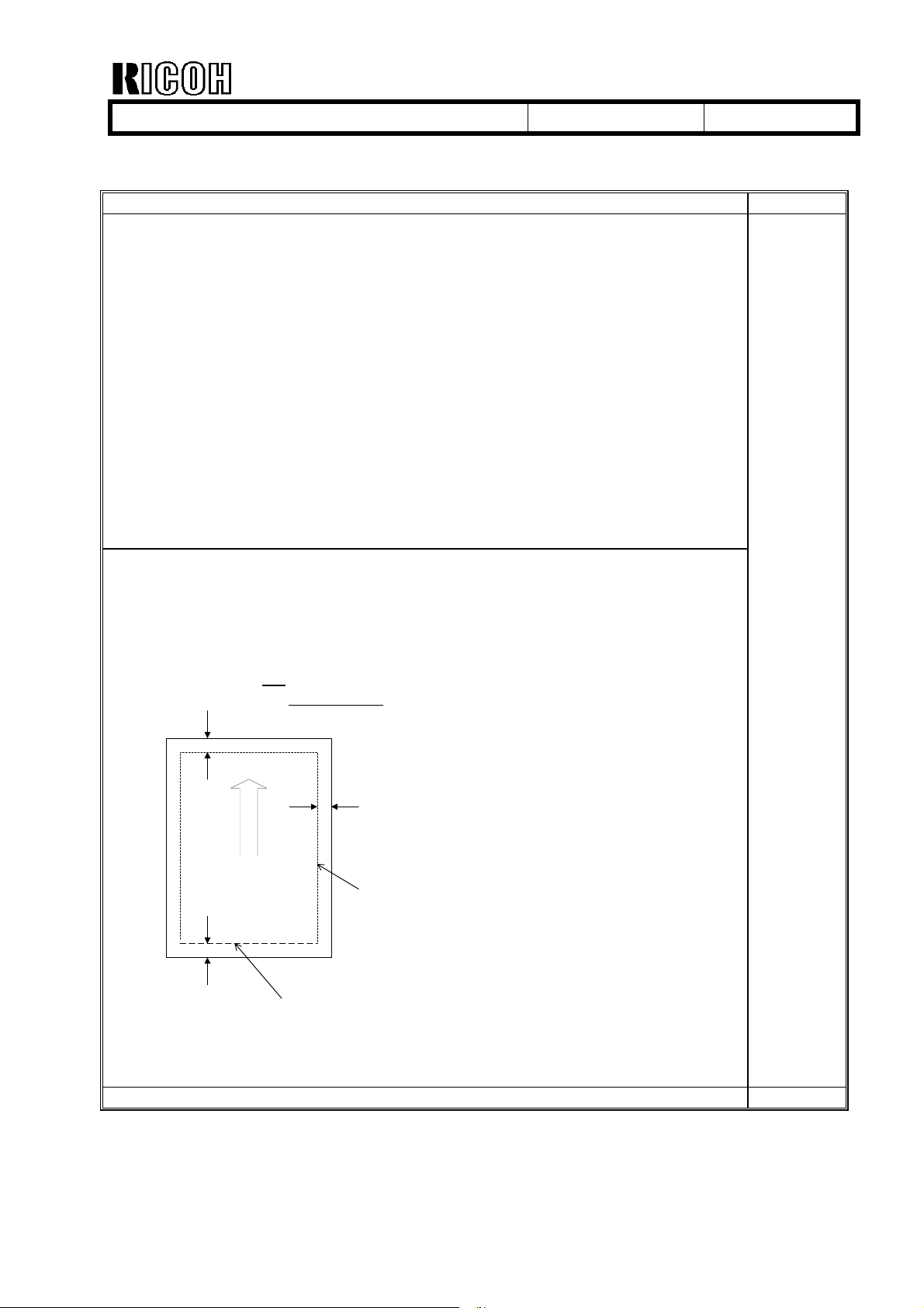
Symptom:
During PCL printing, if data extends over the bottom edge of the printable area, the
machine freezes, displaying "Processing" and operation will no longer be possible.
Condition:
The printer driver is not being used
Print data exists on the bottom edge of the printable area (at 4.2 mm)
4.2
mm
4.2
mm
Printable area
4.2
mm
The problem occurs only if
data exists on the bottom
edge (4.2mm) of the printable
area .
Action:
Update the controller firmware.
1.05
Firmware modified to make corrections in the German wording. 1.02
Page 3
echnical Bulletin
T
PAGE: 3/3
Model:
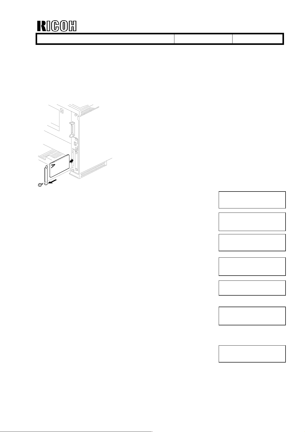
Firmware Updating Procedure
1. Prepare 2 IC cards with the controller firmware.
2. Turn off the main switch.
3. Remove the IC card slot cover on the rear side of the machine as shown.
Model K-P1
Date:
18-Jan-01
No.:
RG058001
4. Insert IC card 1 and turn on the main switch.
“Onboard Sys. 1/2” is displayed.
5. Press “# Enter.”
Note: Make sure that ∗ is displayed.
6. Scroll with the [▲] [▼] key and select “Update.”
Press “# Enter” to start downloading.
The “On Line” LED starts blinking and the machine starts to
download the program.
(Notice that the ∗ mark disappears as the program is
downloaded.)
7. When updating with card 1 is finished, “Update 1/2 task done”
is displayed.
8. Turn off the main switch and replace the card with IC card 2.
Turn on the main switch, then downloading will automatically
start.
Onboard Sys. 1/2
Onboard Sys. 1/2
∗
Update
Updating
∗∗∗∗∗∗∗∗∗∗∗∗∗∗∗∗∗
Update 1/2 task done
Updating
∗∗∗∗∗∗∗∗∗∗∗∗∗∗∗∗∗
9. When updating with card 2 is finished, “Update done” is
displayed.
Then, remove the card, turn on the main switch and print the
configuration sheet.
Check that controller firmware is successfully updated.
Update done
Page 4
echnical Bulletin
T
PAGE: 1/1
Model:
Subject:
From:
Model K-P1
Printer Engine Firmware History
Technical Services Dept., GTS Division
Classification:
Troubleshooting
Mechanical
Paper path
Other ( )
Part information
Electrical
Transmit/receive
Date:
03-Apr-01
Prepared by:
No.:
RG058002
K. Misugi
Action required
Service manual revision
Retrofit information
This RTB announces the printer engine firmware history for model K-P1 (Kir-P1:
G058/G056).
Part Number Version Production
G0525172H 1.11 February ’01
G0525172G 1.10 (does not exist in the field)
G0525172F 1.09 December ’00
G0525172E 1.08 November ’00
G0525172D 1.07 Beginning of mass production
Note: The above firmware is being used in USA, Europe, and Asia models.
Change Descriptions
Descriptions Version
No changes from previous version (only carryover items for Japanese domestic
version).
Firmware modified to correct the following:
•
The machine was showing SC 546 when the symptom was SC 541.
•
Duplex backside (leading edge) registration adjustment was applied only to bypass feeding. Firmware modified so that the adjustment is applied to all paper
sources.
The engine process timing is changed to further ensure that waste toner tank
overflow does not occur when the machine is used under low duty.
1.11
1.09
1.08
Page 5

echnical Bulletin
T
PAGE: 1/3
Model:
Subject:
From:
Model K-P1
Dirty Background on Printouts
Technical Services Dept., GTS Division
Classification:
Troubleshooting
Mechanical
Paper path
Part information
Electrical
Transmit/receive
Date:
09-Apr-01
Prepared by:
No.:
RG058003
K. Misugi
Action required
Service manual revision
Retrofit information
Other ( )
SYMPTOM
Dirty background may occur at installation, either on the right side or throughout the
printout. The following is an example of dirty background on the right side with A4/LT LEF:
Configuration Page
System Reference
xxxxx
xxxxx
Paper Input
xxxxx
xxxxx
System
xxxxx
xxxxx
PCL Menu
xxxxx
Paper Feed Directon
xxxxx
Host Interface
xxxxx
xxxxx
xxxxx
Page 6

echnical Bulletin
T
PAGE: 2/3
Model:
Model K-P1
Date:
09-Apr-01
No.:
RG058003
CAUSE
Dirty background on the right side:
The developer will shift to the left side if the cartridge is tilted as shown below when the
sealing tapes are being removed. This causes toner to be over-supplied on the right side
of the cartridge, which in turn causes the dirty background on the right side of the printout.
Developer accumulates on
left side of the cartridge.
1 2 3 4
1 2 3 4
When removing the tape, place the
machine on a level surface.
Dirty background throughout the page:
This may occur when the user turns on the main switch without removing the tape seals or
when the cartridge has been shaken after the seals are removed.
The position of the toner agitator is adjusted at the factory. When the main switch is turned
on, the main motor turns the agitator. Then, when the user actually removes the seals and
resets the cartridge in the machine, the agitator is no longer in the proper position, and this
causes dirty background on the printouts.
If the cartridge is shaken after the tape seals are removed, dirty background may occur as
the developer is not evenly distributed in the development unit.
Page 7

echnical Bulletin
T
PAGE: 3/3
Model:
Model K-P1
Date:
09-Apr-01
No.:
RG058003
SOLUTION
This symptom may only occur at installation. If it should occur, please advise customers to
print out 30 to 40 pages. In most cases, the symptom will gradually disappear.
In addition, as a preventative measure, please advise customers to be sure and do the
following:
• Remove the seals before turning on the main switch.
• Place the cartridge on a level surface when removing the seals.
• Once the seals have been removed, do not shake the cartridge.
Note: This only applies to cartridge installation and replacement.
From March 2001 production, the following changes were applied to alert customers to
these points.
• Strips of yellow tape have been added that will stick out of the machine, calling
attention to the user to remove the tape seals inside before turning on the main switch.
• A label and caution sheet have been added cautioning the user not to tilt the cartridge
when removing the seals.
Page 8

echnical Bulletin
T
PAGE: 1/2
Model:
Subject:
From:
Kir-P1
LD Unit Position Adjustment
Technical Services Dept., GTS Division
Classification:
Troubleshooting
Mechanical
Paper path
Other ( )
Part information
Electrical
Transmit/receive
Date:
20-Apr-01
Prepared by:
No.:
RG058004
S. Tomoe
Action required
Service manual revision
Retrofit information
The Service Manual procedure for the LD unit position adjustment has been changed from
the first machine of mass production. The new procedure is as follows:
Page 9

echnical Bulletin
T
PAGE: 2/2
Model:
Kir-P1
3.3.5 Laser Diode Unit
[F]
[D]
Date:
20-Apr-01
[C]
[A]
[B]
No.:
RG058004
[E]
Laser Unit (☛ 3.3.4 Laser Unit)
[A]: Spring
[B]: LD unit holders
[C]: Loosen the screw
[D]: Nut
[E]: LD Unit
NOTE: 1) Do not remove the screws that secure the LD board.
2) Do not touch any variable resistors on the LD board.
When installing the LD Unit:
Tighten the screw [C] until the unpainted portion of the screw [F] is not visible.
After installing the LD unit, check the test pattern for the final adjustment (see the following
procedure).
G058R209.WMF
Page 10

Reissued: 20-Apr-01
echnical Bulletin
T
PAGE: 1/2
Model:
Model K-P1
Date:
12-April-01
No.:
RG058001a
RTB Correction
The items in bold italics have been corrected or added.
Subject:
From:
Printer Controller Firmware History
Technical Services Dept., GTS Division
Classification:
Troubleshooting
Mechanical
Paper path
Other ( )
Part information
Electrical
Transmit/receive
Prepared by:
Action required
Service manual revision
Retrofit information
K. Misugi
This RTB informs the printer controller firmware history of the Kir-P1 (G058/G056 model).
Part Number Version Production
G0565920J 1.08 US market: February ’01 production
Europe/Asia: March ’01 production
G0565920G 1.06 US market: Does not exist in the field.
Europe/Asia: February ’01 production
G0565920F 1.05 December ’00 production
(G0565920E) (1.04) Does not exist in the field
(G0565920D) (1.03) Does not exist in the field
G0565920C 1.02 November ’00 production
G0565920B 1.01 1 st mass production
Note: The above firmware is being used in USA, Europe, and Asia models.
Descriptions of the changes (new ones only; for older ones see earlier RTBS)
Descriptions Version
1. Modified so the machine can be used with Axis print servers.
2. Modified to correct Polish and Portuguese wording errors.
Firmware modified to correct the following problem.
Symptom:
In rare cases with graphic images, dark band appears or part of image
becomes black on printouts.
1.08
1.06
Page 11

Reissued: 20-Apr-01
echnical Bulletin
T
PAGE: 2/2
Model:
Firmware Updating Procedure
1. Prepare 2 IC cards with the controller firmware.
2. Turn off the main switch.
3. Remove the IC card slot cover on the rear side of the machine as shown.
Model K-P1
Date:
12-April-01
No.:
RG058001a
4. Insert the IC card-1 and turn on the main switch.
“Onboard Sys. 1/2” is displayed.
5. Press “# Enter.”
Note: Make sure that ∗ is displayed.
6. Scroll with the [▲] [▼] key and select “Update.”
Press “# Enter” to start downloading.
The “On Line” LED starts blinking and the machine starts to
download the program.
(Notice that the ∗ mark disappears as the program is
downloaded.)
7. When updating card-1 is finished, “Update 1/2 task done” is
displayed.
8. Turn off the main switch and replace the card with IC card-2.
Turn on the main switch, then downloading will automatically
start.
Onboard Sys. 1/2
Onboard Sys. 1/2
∗
Update
Updating
∗∗∗∗∗∗∗∗∗∗∗∗∗∗∗∗∗
Update 1/2 task done
Updating
∗∗∗∗∗∗∗∗∗∗∗∗∗∗∗∗∗
9. When updating card-2 is finished, “Update done” is displayed.
Then, remove the card, turn on the main switch and print the
configuration sheet.
Check that controller firmware is successfully updated.
Update done
Page 12

echnical Bulletin
T
PAGE: 1/2
Model:
Subject:
From:
Model K-P1
NIB Firmware History
Technical Services Dept., GTS Division
Classification:
Troubleshooting
Mechanical
Paper path
Other ( )
Part information
Electrical
Transmit/receive
Date:
15-May-01
Prepared by:
No.:
K. Misugi
Action required
Service manual revision
Retrofit information
Printer NIB firmware history for the Kir-P1 (G058/G056 model).
Part Number Version Production
G0585910D 1.49 February ’00 production
G0585910C 1.48 January ’00 production
G0585910B 1.47 December ’00 production
G0585910A 1.46 First mass production
Note: The above firmware is being used in USA, Europe, and Asia models.
RG058005
Page 13

echnical Bulletin
T
PAGE: 2/2
Model:
Firmware modified to correct the following:
1. After a job is canceled from a Unix terminal, the NIB cannot print any print jobs
2. Bi-directional communication over TCP port 9100 is not possible.
3. The NIB stopped LPR printing after user “root” deleted all the spooled jobs.
4. The NIB stopped LPR printing following an input timeout.
5. A PS error report (“io error”) is sometimes printed out during data
Change in Specification:
The word “Emulation” was changed to “Printer Language” in the listed information
displayed by the info command.
Firmware modified to correct the following problem.
1. LPR printing through Mac OS X server was not possible. (Note that Mac OS X
2. The Web Status Monitor had a spelling mistake. (“decomes” ! “becomes”)
3. The last page of a print job from Dazel system (TCP port 9100) was not ejected
4. Disconnecting the Ethernet cable sometimes did not result in a timeout error.
5. TCP/IP setup page in the Web Status Monitor did not check some invalid IP
6. DHCP lease period became 0 (zero) when Solaris 2.6 was used as a DHCP
7. A user name longer than 8 characters caused garbage characters to display in
8. Protocol Up/Down settings were sometimes not activated after a change was
Model K-P1
Descriptions Version
sent from the network.
communication with the NIB when using AppleTalk from a Mac terminal.
server is not officially supported.)
immediately.
address and subnet mask settings.
server.
the “prnlog” result. This does not have any adverse influence on print results.
made.
Date:
15-May-01
No.:
RG058005
1.49
1.48
Change in Specification:
The NIB logs Timeout error in IPP printing in “syslog”.
Firmware modified to correct the following problem.
1. The NIB did not retrieve the infinite lease period setting from the NetWare 5
DHCP server.
2. NIB buffer overflow when Remote Printer Mode was selected.
3. The Web Status Monitor did not have the correct link to IPP Authentication and
Password Change pages.
4. Localized wordings appeared after the NIB reset was modified.
Change in Specification:
None
1.47
Page 14

echnical Bulletin
T
PAGE: 1/4
Model:
Subject:
From:
Model K-P1
New Model K-P1 China Version
Technical Services Dept., GTS Division
Classification:
Troubleshooting
Mechanical
Paper path
Other ( )
Part information
Electrical
Transmit/receive
Date:
19-Jun-01
Prepared by:
No.:
RG058006
K. Misugi
Action required
Service manual revision
Retrofit information
The new model K-P1 (Kir-P1) China model will be released in the line-up of the model KP1 (AP2600/AP2600N) series.
This technical bulletin is to inform the differences between the model K-P1 China version
and the Europe model. They are listed in order of sections that appear in the service
manual.
1. INSTALLATION
1.1.4 POWER REQUIREMENTS
Item Europe Model China Model
Input voltage level 220V ~ 240V, 50Hz/60Hz:
more than 6A
Note: What is mentioned in
the manual is wrong. It should
be 4.5A for the Europe model
also.
220V ~ 240V,
50Hz/60Hz: more than 4.5A
1.3 OPTIONAL UNIT INSTALLATION
Item Europe Model China Model
Envelope Feeder Avialable Not available
IEEE1394 Available Not available
6. DETAILED SECTION DESCRIPTIONS
6.8 IEEE1394 INTERFACE
Disregard descriptions on the IEEE1394 interface because it is not available for the China
model.
Page 15

echnical Bulletin
T
PAGE: 2/4
Model:
Model K-P1
SPECIFICATIONS
1. GENERAL SPECIFICATIONS
Item Europe Model China Model
Printer Languages:
RPCS
Host Interfaces:
IEEE1394
(G058: must remove NIB)
Power Source: 220V - 240V,
50/60 Hz: more than 6.0A
Note: What is mentioned in
the manual is wrong. It should
be 4.5A for the Europe model
also.
Avialable Not available
Optional for G056
Date:
19-Jun-01
No.:
Not available
220V - 240V,
50/60 Hz: more than 4.5A
RG058006
SUPPORTED PAPER SIZES
Europe Model
Paper Size (W x L)
8K 267 x 390 mm N/Y
16K SEF 195 x 267 mm N/Y
16K LEF 267 x 195 mm N/Y
China Model
Paper Size (W x L)
8K 267 x 390 mm Y#/Y
16K SEF 195 x 267 mm Y#/Y
16K LEF 267 x 195 mm Y#/Y
N/A: Option not available
Remarks for the above tables:
Y Supported. The paper size sensor detects the paper size.
#
Y
C
Y
N Not supported.
Supported. The user has to select the correct paper size for the tray.
Supported. The user has to enter the width and length of the paper.
Paper Trays
Main Unit/Option
Eur/Asia
#
#
#
Paper Trays
Main Unit/Option
China model
#
#
#
By-pass
Tray
#
Y
#
Y
#
Y
By-pass
Tray
#
Y
#
Y
#
Y
Env.
Feeder
NY
NY
NY
Env.
Feeder
N/A Y
N/A Y
N/A Y
Duplex
Duplex
Page 16

echnical Bulletin
T
PAGE: 3/4
Model:
Model K-P1
Date:
19-Jun-01
2. SOFTWARE ACCESSORIES
2.1 PRINTER DRIVERS
Item Europe Model China Model
Printer Languages:
RPCS
Avialable Not available
3. MACHINE CONFIGURATION
3.1 SYSTEM COMPONENTS
Item Europe Model China Model
Envelope Feeder (G556) Avialable Not available
IEEE1394 (G561) Avialable Not available
No.:
RG058006
4. OPTIONAL EQUIPMENT
4.2 ENVELOPE FEEDER
Not available for the China model.
Page 17

echnical Bulletin
T
PAGE: 4/4
Model:
Model K-P1
Date:
19-Jun-01
No.:
RG058006
PARTS CATALOG INFORMATION
Main Unit:
The following parts for the China model are different from the Europe/Asia model.
Index
3-27 --- G0588677 Setup Guide - China
3-30 G0531940 G0531970 Operation Panel Ass’y - China
11-18 GZ000003 GZ000004 Power Supply Cord - CHN
23-5 G0565712 G0565713 Controller Board
25-15 G0525211 G0525214 Power Supply Unit - 230V CHN
Envelope Feeder:
Europe/Asia
Model
China Model Description
The envelope feeder is not available for the China model.
Page 18

Reissued: 20-Jun-01
echnical Bulletin
T
PAGE: 1/4
Model:
Model K-P1
Date:
09-Apr-01
No.:
RG058003a
RTB Correction
This page has been added to the original bulletin.
Subject:
From:
Dirty Background on Printouts
Technical Services Dept., GTS Division
Classification:
Troubleshooting
Mechanical
Paper path
Other ( )
Part information
Electrical
Transmit/receive
Prepared by:
Action required
Service manual revision
Retrofit information
K. Misugi
The cartridge has been modified from June production so that dirty background will not
occur at installation even when the cartridge is tilted.
A green decal is added so the new cartridge can be distinguished from the old type.
The same decal is also placed on the supply cartridge, next to the bar-code label on the
box.
Green decal on the new cartridge.
1 2 3 4
This RTB is to remind you of the remarks for cartridge installation.
• Place the cartridge on a level surface when removing the sealing tapes on the
cartridge.
• Remove the sealing tapes on the cartridge before turning on the main switch.
• Once the seals have been removed, do not shake the cartridge.
Note: This only applies to cartridge installation and replacement.
Please refer to the original RTB, which was previously issued for the dirty background
problem at installation.
 Loading...