

Ricoh AFICIO CL5000 User Manual

Option Setup Guide
For safety, please read this manual carefully before you use this product and keep it handy
for future reference.

Introduction
To get maximum versatility from this machine all operators should carefully read and follow the instructions in this manual. Please keep this manual in a handy place near the machine.
Please read the Safety Information in Maintenance Guide 1 before using this machine. It contains important information related to USER SAFETY and PREVENTING EQUIPMENT PROBLEMS.
Important
Contents of this manual are subject to change without prior notice. In no event will the company be liable for direct, indirect, special, incidental, or consequential damages as a result of handling or operating the machine.
Caution:
Use of controls or adjustment or performance of procedures other than those specified in this manual
might result in hazardous radiation exposure.
Do not attempt any maintenance or troubleshooting other than that mentioned in this manual. This
printer contains a laser beam generator and direct exposure to laser beams can cause permanent eye
damage.
Notes:
Some illustrations in this manual might be slightly different from the machine.
Certain options might not be available in some countries. For details, please contact your local dealer.
Two kinds of size notation are employed in this manual. With this machine refer to the inch version.
For good print quality, the supplier recommends that you use genuine toner from the supplier.
The supplier shall not be responsible for any damage or expense that might result from the use of parts
other than genuine parts from the supplier with your office products.
Trademarks
Microsoft, Windows and Windows NT are registered trademarks of Microsoft Corporation in the United
States and/or other countries.
IPS-PRINT Printer Language Emulation Copyright© 1999-2000 Oak Technology, Inc., All rights reserved.
Other product names used herein are for identification purposes only and might be trademarks of their
respective companies. We disclaim any and all rights in those marks.
The proper names of the Windows operating systems are as follows:
®
•Microsoft
Windows® 95 operating system
•Microsoft® Windows® 98 operating system
•Microsoft® Windows® Millennium Edition (Windows Me)
®
•Microsoft
Windows ® 2000 Professional
•Microsoft® Windows ® 2000 Server
•Microsoft® Windows® XP Professional
®
•Microsoft
Windows® XP Home Edition
•Microsoft® Windows NT® Server operating system Version 4.0
•Microsoft® Windows NT® Workstation operating system Version 4.0

TABLE OF CONTENTS
How to Read This Manual .....................................................................................1
1. Options
Available Options...................................................................................................3
PAPER FEED UNIT Type 5000 ..............................................................................7
Interchange Unit Type 5000 ................................................................................11
Duplex Unit Type 5000.........................................................................................15
SR780 (500-sheet Finisher).................................................................................20
Using the Output Guide............................................................................................ 23
Mail Bin Type 5000 (4-bin Mailbox) ....................................................................24
Memory Unit Type C (SDRAM Module) ..............................................................28
Printer Hard Disk Type 5000 ............................................................................... 32
1394 Interface Unit Type 4510.............................................................................36
Connecting the cable to the 1394 Interface Unit ......................................................40
802.11b Interface Unit Type A.............................................................................41
IEEE 802.11b (Wireless LAN) Configuration ........................................................... 45
User Account Enhance Unit Type B...................................................................49
INDEX......................................................................................................... 53
i

ii

How to Read This Manual
R
R
Symbols
In this manual, the following symbols are used:
WARNING:
This symbol indicates a potentially hazardous situation which, if instructions
are not followed, could result in death or serious injury.
CAUTION:
This symbol indicates a potentially hazardous situation which, if instructions
are not followed, may result in minor or moderate injury or damage to property.
* The statements above are notes for your safety.
Important
If this instruction is not followed, paper might be misfed, or data might be lost.
Be sure to read this.
Preparation
This symbol indicates the prior knowledge or preparations required before operating.
Note
This symbol indicates precautions for operation, or actions to take after misoperation.
Limitation
This symbol indicates numerical limits, functions that cannot be used together,
or conditions in which a particular function cannot be used.
Reference
This symbol indicates a reference.
[]
Keys that appear on the machine's panel display.
Keys and buttons that appear on the computer's display.
{}
Keys built into the machine's control panel.
Keys on the computer's keyboard.
1

2
1. Options
R
Available Options
CAUTION:
• Before installing options, the machine should be turned off and unplugged
for at least an hour. Components inside the machine become very hot, and
can cause a burn if touched.
• Before moving the machine, unplug the power cable from the outlet. If the
cable is unplugged abruptly, it could become damaged. Damaged plugs or
cables can cause an electrical or fire hazard.
• When lifting the machine, use the grips on both sides. The machine could
break or cause an injury if dropped.
By installing options, you can improve the printer performance and have an expanded variety of features to use. For the specifications of each option, see the
Administrator Reference.
When installing multiple options on the printer, we recommend the following
order of installation.
Important
❒ Rating voltage of the connector for options: Max. DC 24 V.
❖❖❖❖ Flow of Option Installation
A
Attach the 500-sheet Paper Feed
Unit.
(PAPER FEED UNIT Type 5000)
T
B
Attach the Interchange Unit.
(Interchange Unit Type 5000)
T
C
Attach the Duplex Unit.
(Duplex Unit Type 5000)
T
Attach the Paper Feed Unit to the bottom of the printer.
You can attach up to two Paper Feed Units.
Attach to the top of the printer for using the Duplex Unit, 4bin Mailbox or 500-sheet Finisher.
Attach to the right of the printer after attaching the Interchange Unit.
D
Attach the 500-sheet Finisher.
(SR780)
T
Attach to the top of the printer after attaching the Interchange Unit.
If you choose to attach the 500-sheet Finisher, you cannot attach the 4-bin Mailbox.
3

Options
1
E
Attach the 4-bin Mailbox.
(Mail Bin Type 5000)
T
F
Install the SDRAM Module.
(Memory Unit Type C)
T
G
Install the Printer Hard Disk.
(Printer Hard Disk Type 5000)
T
H
Install the 1394 Interface Unit.
(1394 Interface Unit Type 4510)
T
I
Install the 802.11b Interface Unit
(802.11b Interface Unit Type A)
Attach to the top of the printer after attaching the Interchange Unit.
If you choose to attach the 4-bin Mailbox, you cannot attach
the 500-sheet Finisher.
Install the module to the SDRAM module slot on the controller board.
64MB, 128MB, and 256MB Memory Units are available.
Install the Printer Hard Disk to the controller board.
Install the 1394 Interface Unit to the 1394 I/F slot on the controller board.
If you choose to install the 1394 Interface Unit, you cannot
install the 802.11b Interface Unit or USB2.0 Interface Unit.
Install the 802.11b Interface Unit to the slot on the controller
board.
If you choose to install the 802.11b Interface Unit, you cannot install the 1394 Interface Unit or USB2.0 Interface Unit.
T
J
Install the User Account Enhance
Unit.
(User Account Enhance Unit
Type B)
Install the module to the User Account Enhance Unit slot on
the controller board.
Install options in the positions as shown in the illustration.
4

❖❖❖❖ Exterior
Available Options
12
1
3
4
5
1. SR780 (500-sheet Finisher)
Performs Job Separation and staples.
Outputs up to 500 sheets.
⇒ p.20 “SR780 (500-sheet Finisher)”
2. Mail Bin Type 5000 (4-bin Mail-
box)
Sorts printed documents from multiple users. Outputs up to 500 (125 × 4)
sheets.
⇒ p.24 “Mail Bin Type 5000 (4-bin
Mailbox)”
4. Duplex Unit Type 5000
Makes duplex prints.
⇒ p.15 “Duplex Unit Type 5000”
5. PAPER FEED UNIT Type 5000
Loads up to 500 sheets of paper. Up to
two units can be installed to the printer, and "Tray 2" appears on the panel
display for the first unit and "Tray 3"
appears on the panel display for the
second unit.
⇒ p.7 “PAPER FEED UNIT Type
5000”
3. Interchange Unit Type 5000
Sends paper to the Duplex Unit, 500sheet Finisher or 4-bin Mailbox.
⇒ p.11 “Interchange Unit Type 5000”
Important
❒ Attach the Interchange Unit before attaching the Duplex Unit, 500-sheet
Finisher or 4-bin Mailbox.
❒ You can attach either one of the 500-sheet Finisher or 4-bin Mailbox to the
printer.
ZESP001J
5

Options
❖❖❖❖ Interior
2
1
1
1. Printer Hard Disk Type 5000
Install Printer Hard Disk to the controller board.
⇒ p.32 “Printer Hard Disk Type 5000”
2. Memory Unit Type C (SDRAM
Module)
Install 64MB, 128MB, or 256MB RAM
into the slot on the controller board.
⇒ p.28 “ Memory Unit Type C
(SDRAM Module)”
3
4
5
ZESPK002N
3. 1394 Interface Unit Type 4510
⇒ p.36 “1394 Interface Unit Type
4510”
4. 802.11b Interface Unit Type A
⇒ p.41 “802.11b Interface Unit Type
A”
5. User Account Enhance Unit Type
B
⇒ p.49 “User Account Enhance Unit
Type B”
Important
❒ Remove USB2.0 Interface Board when you install 1394 Interface Unit or
802.11b Intaerface Unit.
❒ 1394 Interface Unit, 802.11b Interface Unit and USB2.0 Interface Board cannot
be installed in the printer at the same time.
6

PAPER FEED UNIT Type 5000
R
PAPER FEED UNIT Type 5000
Preparation
When installing multiple options,
install the Paper Feed Unit first.
Two people are needed to install
the Paper Feed Unit. Start the installation with two people.
Up to two Paper Feed Units can be
installed to the printer. When installing two units, connect the two
units by following the procedure
for connecting the unit and the
printer. Then, place the printer on
the connected two Paper Feed
Units.
CAUTION:
• When moving the machine,
each person should hold the
handles that are located on opposite sides, and then lift it slowly. Lifting it carelessly or
dropping it may cause an injury.
• When moving the Paper Feed
Unit, hold the handles that are
located on the top of the unit,
and then lift it slowly. Lifting it
carelessly or dropping it may
cause an injury.
Note
❒ The printer weighs approximately
60 kg (130 lb.).
Turn off the power switch, and
AAAA
then unplug the power cable.
Hold the Paper Feed Unit as
BBBB
shown in the illustration, and
then place it on a flat surface near
the place where the machines are
to be installed.
Note
❒ Be sure to work in a place with
enough space, so that you can
get in the back of the printer.
Remove the adhesive tapes.
CCCC
Open the tray of the Paper Feed
DDDD
Unit, and then remove the supplied parts and the packing materials.
1
ZESP900J
❒ The PAPER FEED UNIT weighs
approximately 15 kg (33 lb.).
❒ "Tray 2" appears on the panel dis-
play when only one unit is installed. "Tray 3" appears on the
panel display for the second unit
when two units are installed.
ZESP140J
7

Options
1
The packing materials are put in
two places as shown in the illustration.
Close the tray firmly.
EEEE
Check the contents.
FFFF
❖❖❖❖ Two metal fittings
ZESP602J
Pull out the holding handles from
GGGG
the sides of the printer.
Note
❒ Be sure to pull out the handles
all the way.
Lift the printer, adjust the front
HHHH
sides of the printer and the Paper
Feed Unit, and then lower the
printer slowly into place of the
Paper Feed Unit.
ZESP006J
❖❖❖❖ Two screws (for the front)
❖❖❖❖ Two screws (for the rear)
Important
❒ When installing two Paper Feed
Units, connect the two units by
following the procedure for
connecting the unit and the
printer. Then, place the printer
on the connected two Paper
Feed Units.
❒ When lifting the printer, hold
the handles of the printer with
two people.
ZESP144J
8
PAPER FEED UNIT Type 5000
Push in the holding handles that
IIII
you pulled out in step
Pull out Tray 1 (standard input
JJJJ
tray) slowly while lifting it up a
little.
Fasten the two screws (for the
KKKK
front) as shown in the illustration.
.
GGGG
ZESP008J
Close Tray 1 firmly.
LLLL
Place the two metal fittings on the
MMMM
back of the printer, and then fasten the screws (for the rear) over
them as shown in the illustration.
Use a coin to fasten them tightly.
Stick the label above the handle
NNNN
on the front of the Paper Feed
Unit.
1
ZESP010J
ZESP009J
Use a coin to fasten them tightly.
To connect two Paper Feed Units,
fasten the two screws (for the
front) as shown in the illustration.
ZESP910J
ZESP126J
Note
❒ After finishing installation, you
can check whether the Paper
Feed Unit is installed properly.
Print the configuration page
from the "List/Test Print"
menu. If it is installed properly,
you will see "Tray 2" or "Tray 3"
under the "Options" list.
9

1
Options
❒ If the Paper Feed Unit is not in-
stalled properly, reinstall from
step
properly even after reinstallation, contact your sales or service representative.
Reference
See "Using the Control Panel" in
the Administrator Reference for
printing the configuration page.
See "Loading Paper" in Maintenance Guide 2 for loading paper
in the Paper Feed Unit.
. If you cannot install it
A
10
Interchange Unit Type 5000
R
Interchange Unit Type 5000
Preparation
Install the Interchange Unit before
installing the Duplex Unit, 500sheet Finisher or 4-bin Mailbox.
CAUTION:
• The inside of the machine becomes very hot. Do not touch the
parts with a label indicating "v"
(means hot surface). Touching
"v" (means hot surface) could
result in a burn.
Turn off the power switch, and
AAAA
then unplug the power cable.
Remove the adhesive tapes.
BBBB
Open the Bypass Tray.
CCCC
Open the right cover of the print-
DDDD
er by pushing up the handle.
Stand on the right of the printer,
EEEE
and then remove the upper right
cover of the printer.
A Open the upper right cover.
1
ZESP155J
ZESP253J
Note
❒ Remove paper on the Bypass
Tray to prevent them from falling.
ZESP156J
B Press the cover to the right (AAAA),
and then lift the left edge (BBBB)
to remove it from the printer.
ZESP254J
11

Options
1
Note
❒ The removed cover will not
be used.
Stand on the right of the printer,
FFFF
and then remove the remaining of
the upper right cover.
A Remove the screw that is fas-
tening the upper right cover.
Note
❒ The removed screw will not
be used.
B Lift the right edge (AAAA), and
then push to the left (BBBB) to remove it.
Remove the top cover of the Inter-
GGGG
change Unit. First, pull up the
stopper (AAAA), and then lift the cover (BBBB).
Note
❒ You need the removed cover in
step
Stand on the right of the printer,
HHHH
and then install the Interchange
Unit.
A Hold the unit with both hands,
and then slide with the metal
part (AAAA) of the Interchange
Unit touching the metal part
(BBBB) of the printer.
.
J
ZESP901J
12
ZESP255J
ZESP903J
Note
❒ The removed cover will not
be used.
Interchange Unit Type 5000
Insert the unit by sliding it onto
the printer as shown in the illustration.
ZESP902J
B Open the right cover of the In-
terchange Unit.
D Fasten the two screws on the
Interchange Unit until they are
tight.
1
ZESP161J
E Close the right cover of the In-
terchange Unit.
ZESP159J
C Press the two projections on
the Interchange Unit so that
they securely fit into the holes
of the printer.
ZESP160J
Close the right cover of the print-
IIII
er.
Note
❒ Press "PUSH" to close the cover
firmly.
ZESP162J
ZESP179J
13
Options
1
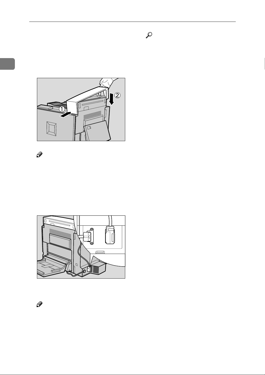
Set the top cover of the Inter-
JJJJ
change Unit that you removed in
step
side of the printer (AAAA), and then
push the other end until it clicks
into its place (BBBB).
❒ You do not have to set the top
. First, put it on the front
GGGG
Note
cover of the Interchange Unit at
this point if you install the 500sheet Finisher or the 4-bin Mailbox. Go to step
.
K
Reference
See "Using the Control Panel" in
the Administrator Reference for
printing the configuration page.
ZESP904J
Connect the Interchange Unit ca-
KKKK
ble to the back of the printer.
Close the Bypass Tray.
LLLL
Note
❒ If the Interchange Unit is not in-
stalled properly, reinstall from
step
properly even after reinstallation, contact your sales or service representative.
. If you cannot install it
A
ZESP257J
14
 Loading...