

Page 1

RICOH Technical
Bulletin
PAGE: 1/3
Model:
Subject:
From:
Classification:
While SP2-207-2 (Toner Bank Toner Supply) is performed at installation, the rotation of
the toner hopper gear (AB013748: Joint Gear -15Z) may cause an oversupply of toner
from the hopper to the development unit. This in turn causes relatively high image density
in copies/printouts made just following installation. To correct this, machines in massproduction have been modi fied as fol lows:
Bellini
Toner Hopper Gear Replcement at Installation
Technical Services Dept., GTS Division
Troubleshooting
Mechanical
Paper path
Other ( )
Part information
Electrical
Transmit/receive
Date:
15-Dec-99
Prepared by:
Action required
Service manual revision
Retrofit information
H.K.
No.:
RA294001
Temporary Solution
The toner hopper contains a red idler gear (A2943255: Idler Gear - 15Z). This gear
reduces the drive supplied to the toner hopper and prevents the oversupply of toner that
occurs in the initial period following installation .
The toner hopper gear for normal operation (White gear:AB013748: Joint Gear -15Z) and
a spare C-ring (07200060B: Retaining Ring - M6) have been packed in the accessory
plastic bag.
The procedure for the Toner Hopper Drive Gear Replacement (Joint Gear - 15Z) has been
packed in the accessory plastic bag. The procedure is also included on page 2/3 of this
bulletin.
Action required
Replace the red idler gear with the white gear after carrying out SP2-207-2 (Toner Bank
Toner Supply) by referring to the procedure for the Toner Hopper Drive Gear Replacement
(Joint Gear - 15Z) packed in the accessory plastic bag. The red idler gear is not
necessary after machine installation.
Permanent Solution
The permanent solution is basically the same as the temporary solution. To facilitate gear
replacement, the gear has been mounted with screw (09513006B: Philips Screw With Flat
Washer - M3x6) instead of a C-ring. The procedure is included on page 3/3 of this bulletin.
Regarding the cut-in serial numbers for this modification, we will issue an MB as soon as
they are available.
Action required
Same as “Action required” described above.
Page 2
RICOH Technical
Bulletin
PAGE: 2/3
Model:
The part number of the toner hopper unit will be changed from #A2943200 to a new part
number due to the above modification. If the toner hopper unit is replaced in the field,
replace the red idler gear in the new toner hopper with the white gear in the original toner
hopper unit.
The toner hopper unit part number will be therefore changed because of the gear
replacement and C-ring substitution. As the spare part of #A2943200 contains the white
gear, the old unit part can be replaced in the machines installed in the field. It is not
necessary to change the red gear to a white gear.
The following is the procedure packed in the accessory plastic bag as the temporary
solution. After step #35, remove the development unit and follow the instruction marked
with an asterisk (
Bellini
. Then, put back the development unit.
*
)
Date:
15-Dec-99
No.:
RA294001
Toner Hopper Drive Gear (Joint Gear 15Z) Replacement
Please add the gear replacement procedure (*) after step #35 (Toner Bank Toner Supply).
#35. Supply toner from the toner bank to the toner hopper as follows:
1) Select SP2-207-2 (Toner Bank Toner Suppl y)
2) Press the “Start key” on the LCD.
# *
#36. Change the paper size for all paper trays to suit the customer’s request.
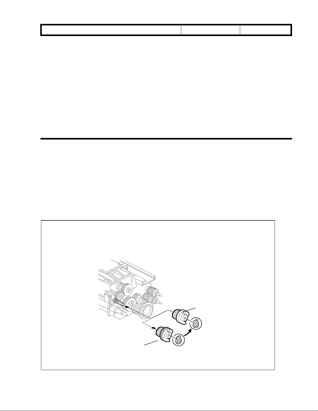
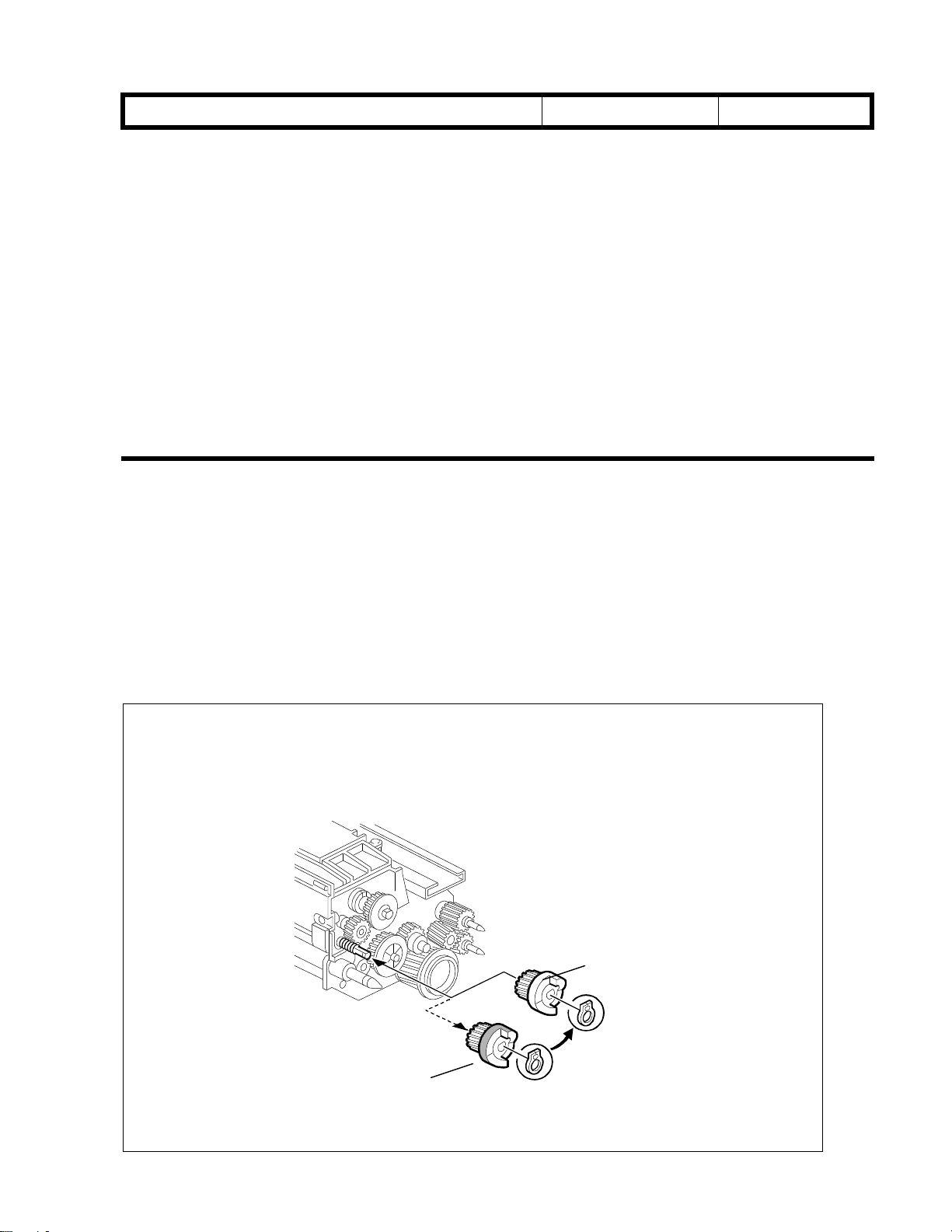
Remove the Joint Gear 15Z that has been marked red [A].
*
Replace it with the white gear [B] and a spare C-ring packed in the accessory
plastic bag.
B
A
Toner Hopper Unit Rear View
Page 3
RICOH Technical
Bulletin
PAGE: 3/3
Model:
The following is the procedure packed in the accessory plastic bag as the permanent
solution. After step #35, remove the development unit and follow the instruction marked
with an asterisk (
Bellini
. Then, put back the development unit.
*
)
Date:
15-Dec-99
No.:
RA294001
Toner Hopper Dr ive Gear (Joint Gear 15Z) Replacement
Please add the gear replacement procedure after step #35 (Toner Bank Toner Supply).
#35. Supply toner from the toner bank to the toner hopper as follows:
1) Select SP2-207-2 (Toner Bank Toner Suppl y)
2) Press the “Start key” on the LCD.
*:
#36. Change the paper size for all paper trays to suit the customer’s request.
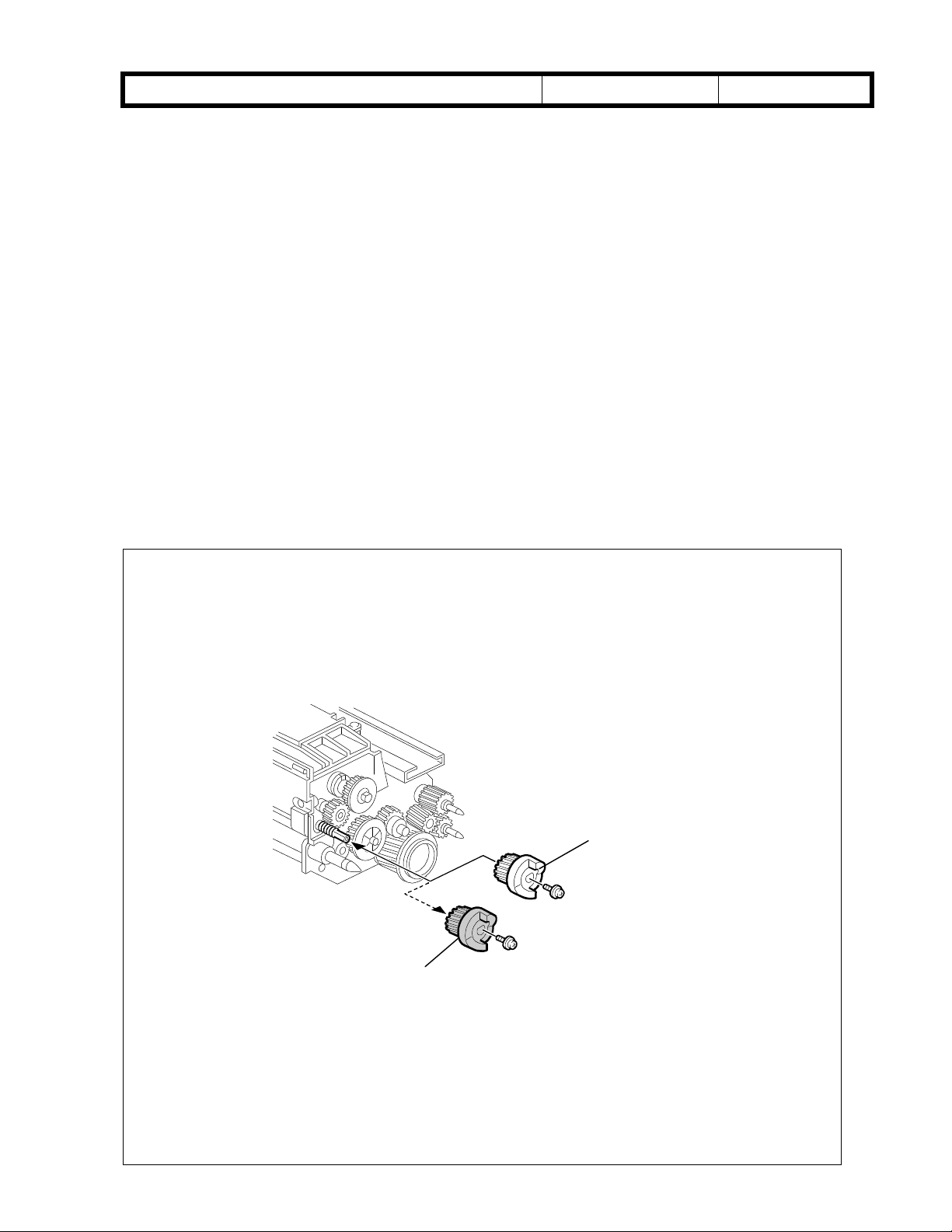
*
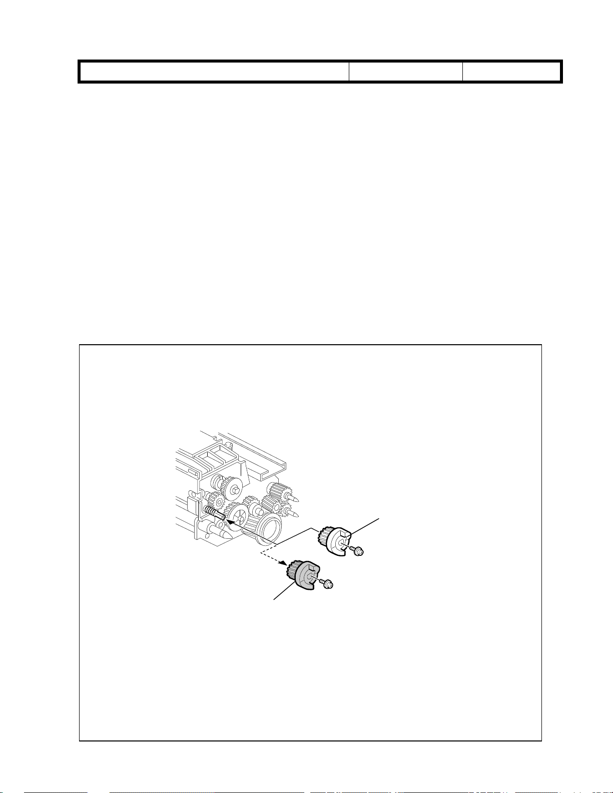
Remove the Joint Gear 15Z that has been marked red [A].
Replace it with the white gear [B] and a spare C-ring packed in the
accessory plastic bag.
B
A
Toner Hopper Unit Rear View
Page 4

RICOH Technical
Reissued: 03-Feb-00
Bulletin
PAGE: 1/5
Model:
RTB Correction
The following items in bold italics have been added.
Subject:
From:
Classification:
We have found that toner in the toner transport tube may be blocked due to vibrations during
machine transportation. Please note the following remarks and do the
machine is transported.
Bellini
Transportation Remarks
Technical Services Dept., GTS Division
Troubleshooting
Mechanical
Paper path
Other ( )
Part information
Electrical
Transmit/receive
Date:
15-Dec-99
Prepared by:
Action required
Service manual revision
Retrofit information
procedure when the
H.K.
No.:
RA294002a
3.9 TRANSPORTATION REMARKS
3.9.1 TONER TRANSPORT TUBE CLEANING
NOTE:
1) When transporting the machine, do the following operations. Otherwise, the
toner system may be blocked.
2) Be careful not to drop the toner.
3) If this procedure is not carried out, SC592 (Toner Bank Motor Error) or SC495
(Toner Bottle Unit Error) could be displayed and the toner transport tube and
screw should be replaced.
I. Procedure before transportation (Removing toner from the toner transport tube):
1. Close the toner bottle cap using SP5-804-62 (upper bottle) or -63 (lower bottle). Then
remove the toner bottles from the bank.
2. Remove the upper rear and lower rear covers.
3. Remove the upper left cover, lower left cover, upper right cover .
4. Remove the two screws [A] securing the toner supply cylinder.
5. Cover the end of the toner transport coil tube [B] with a plastic bag.
NOTE: See “Note for step 6”.
6. Energize the toner bank motor and toner supply coil clutch for 2 minutes using SP5804-61 and -64 to remove all of the toner in the supply tube.
7. Re-install all removed parts except for the toner bottles.
NOTE for step 6:
Take extra caution not to bend the
toner transport coil tube [B]. If it is
bent, this can cause the coil (screw)
inside to be overloaded, locked, or
damaged. SC592 will be displayed,
and the coil (screw) inside should
be replaced.
[B]
Page 5

RICOH Technical
Reissued: 03-Feb-00
Bulletin
PAGE: 2/5
Model:
NOTE: Make sure that three tubes are connected to the toner supply cylinder when
putting it back.
II. Procedure after transportation (loading toner into the toner transport tube):
1. Load the toner bottles into the toner bank.
2. Remove the upper right cover. Open the cylinder top cover and clean the inner surface
3. Energize the toner bank motor using SP5-804-61.
4. Energize the toner bottle motors for 5 to 6 seconds using SP5-804-59, -60.
5. Energize the toner supply coil clutch using SP5-804-64.
6. 50 to 60 seconds later, toner is supplied to the toner supply cylinder. Make sure that
7. Turn off the toner supply coil clutch and then the toner bank motor.
8. Return all removed parts.
Bellini
of the cylinder with a cloth to check the toner supply at step 6. Then, close the cylinder
top cover.
toner is properly supplied to the cylinder.
Date:
15-Dec-99
No.:
RA294002a
Note:
Do not energize the toner bottle motors for a long time, otherwise toner overflows in
the toner entrance tank.
Page 6
RICOH Technical
Reissued: 03-Feb-00
Bulletin
PAGE: 3/5
Model:
Upon reviewing the previous Toner Bank Unit Removal procedure in the Service Manual,
the above procedures on pp.1-2 have been added as step 1:
6.11.2 TONER BANK UNIT REMOVAL
1. Follow steps 1 to 6 of the procedure before transportation.
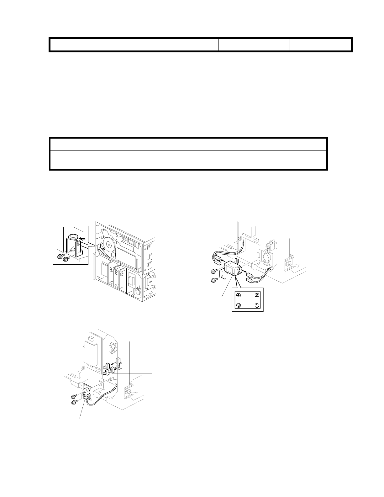
2. Turn off the main switch and unplug the power cord. Follow steps 1 and 2 of the waste
toner bottle removal procedure.
I
Make sure that the power cord is unplugged before removing the noise
filter in the next step.
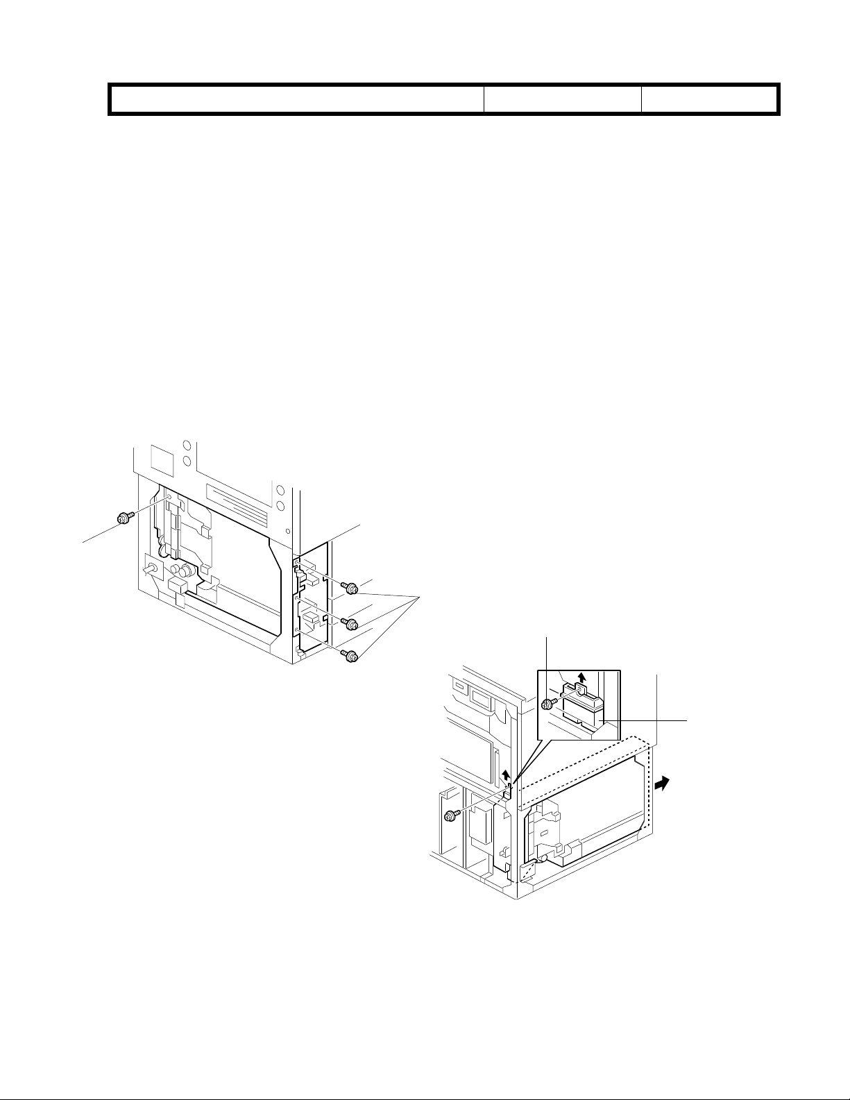
3 Remove the noise filter [C] (2 screws and 4 connectors; upper: Ã, Á white lower: Â,
4 Disconnect the three connectors [E] from the toner bank unit.
Bellini
CAUTION
yellow) and toner bank motor [D] (2 screws, 1 connector).
Date:
15-Dec-99
No.:
RA294002a
À
A294R903.WMF
[D]
A294R905.WMF
[C]
A294R904.WMF
[E]
Page 7
RICOH Technical
Reissued: 03-Feb-00
Bulletin
PAGE: 4/5
Model:
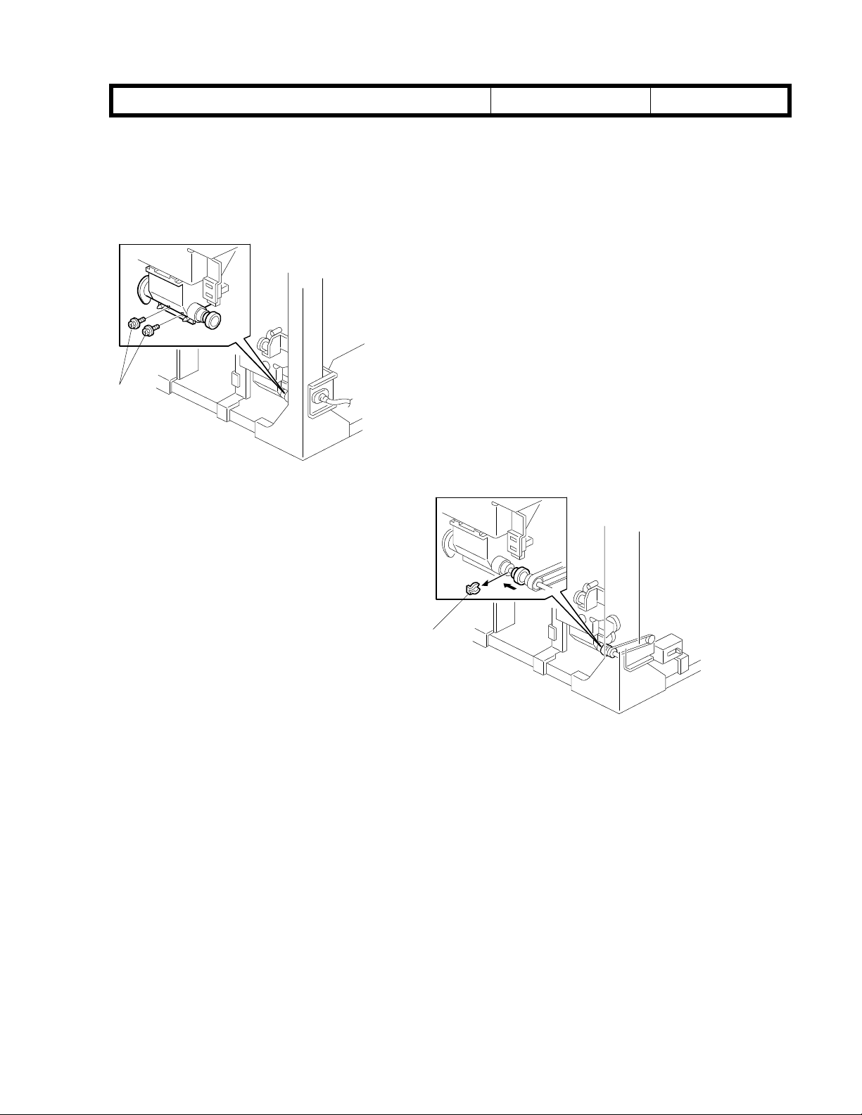
5 Remove the two screws [A] securing the toner transport coil tube.
6 While sliding the toner transport coil tube, remove the snap ring [B].
[A]
A294R907.WMF
Bellini
Date:
15-Dec-99
No.:
RA294002a
[B]
A294R906.WMF
Page 8
RICOH Technical
Reissued: 03-Feb-00
Bulletin
PAGE: 5/5
Model:
7 Remove the four screws [A] securing the toner bank unit.
8 Remove the screw [B] securing the toner recycling and collection cover [C].
9 While lifting the toner recycling and collection cover [C], pull out the toner bank unit.
10 Remove the plastic bag from the toner transport coil tube. Re-connect the toner supply
11 Perform Procedure II. described on pp.1-2 of this bulletin (“After Transportation”).
Bellini
NOTE:
NOTE:
cylinder to the toner transport coil tube (2 screws).
Try not to spill any toner from the toner bank.
When pullin g out the toner bank unit, toner may leak out of the junction
between the tube and toner bank. Place a cloth on the machine bottom plate
so that the plate does not become dirty.
Date:
15-Dec-99
No.:
RA294002a
[A]
[A]
[B]
A294R908.WMF
[C]
A294R909.WMF
Page 9
RICOH Technical
Bulletin
PAGE: 1/1
Model:
Subject:
From:
Classification:
Bellini
SC495 (After installation)
Technical Services Dept., GTS Division
Troubleshooting
Mechanical
Paper path
Other ( )
Date:
Prepared by:
Part information
Electrical
Transmit/receive
31-Dec-99
Action required
Service manual revision
Retrofit information
No.:
RA294003
J. Mochizuki
SYMPTOM
SC495 is displayed while making copies. This symptom occurs soon after the machine
installation is completed.
CAUSE
When SP220 7 is performed at installation, the toner supply from the toner bank stops
before enough toner is supplied to the toner hopper.
This is because the toner hopper sensor tends to misdetect the toner amount before the
toner inside the toner hopper is stabilized.
SOLUTION
If this symptom occurs in the field, turn the main switch off and on. When enough toner is
supplied to the toner hopper, this problem will not reo ccur.
For a permanent countermeasure, the firmware has been changed to change the SP2207
operation. The firmware version was changed from Ver. 7.1 to Ver. 7.8.1.
The new firmware will be used from the January 2000 production.
Before modification:
While performing SP2207 (Forced toner supply), toner supply from the toner bank stops 4
minutes after the toner hopper sensor detects the toner.
After modification:
Toner supply stops 6 minutes after starting SP2207.
The part numbers (suffix) have been changed as follows:
Old (Ver 7.1) New (Ver 7.8.1)
P/N for the firmware (NA) A2945610B A2945610C
P/N for the firmware (EU) A2945660B A2945660C
It is recommended to install the new software (ver 7.8.1) before starting toner initial setting
with SP2207.
Page 10
T
echnical
B
ulletin
PAGE: 1/3
Model:
Subject:
From:
Classification:
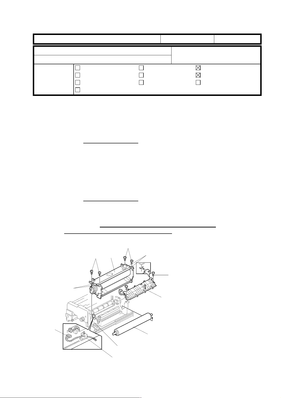
Note on reinstallation of the hot roller unit:
We have found that an audible resonance may occur inside the fusing unit while making
copies. To correct this, the method for reinstalling the hot rolle r unit has been changed.
Please correct the note on page 6-85 in the service manual as follows:
Old
5. Remove the four M5 pan head screws [B] and remove the hot roller unit [C].
New
Bellini
Noise from the fusing unit
Technical Services Dept., GTS Division
Troubleshooting
Mechanical
Paper path
Other ( )
NOTE: 1) When re -installing the hot roller unit, make sure that the flanges of
the ball bearings in the hot roller unit are set inside the fusing exit
side plate [D] and the gear in the hot roller unit is installed on the
rear side.
2) Secure the M5 pan head screws at the rear side first. Then, secure
the screws at the front side.
Part information
Electrical
Transmit/receive
Date:
31-Jan-00
Prepared by:
No.:
RA294004
H. K.
Action required
Service manual revision
Retrofit information
5. Remove the four M5 pan head screws [B] and remove the hot roller unit [C].
NOTE: 1) When re-installing the hot roller unit, make sure that the flanges of
the ball bearings in the hot roller unit are set inside the fusing exit side
plate [D] and the gear in the hot roller unit is installed on the rear side.
2) Secure the M5 pan head screws in the following order:
left-rear, right-front, right-rear, left-front.
[B]
[A]: Do not remove these screws.
[E]
[F]
[G]
[A]
[C][B]
[A]
[I]
A294R503.WMF
[D]
[H]
Page 11
T
echnical
B
ulletin
PAGE: 2/3
Model:
Bellini
Date:
31-Jan-00
No.:
RA294004
Noise (resonance) during copying
An audible resonance may occur during copying. To correct this, machines in production
have been modified as follow s:
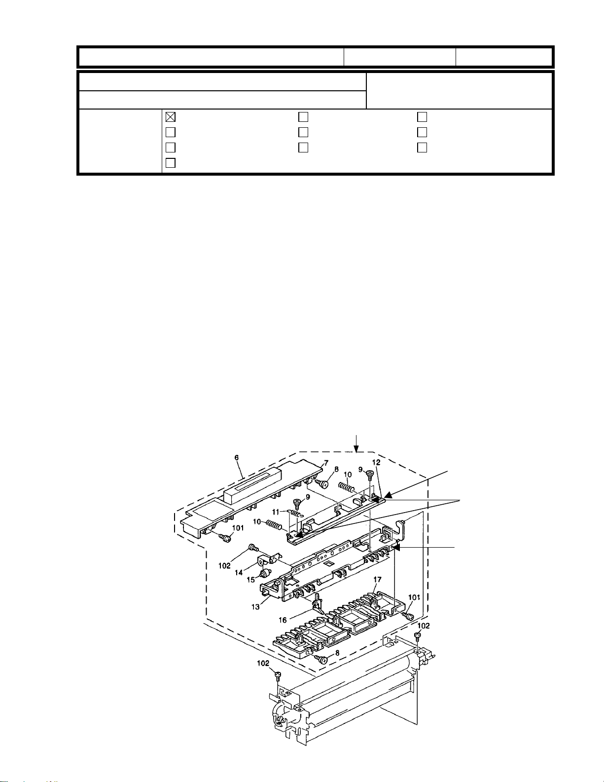
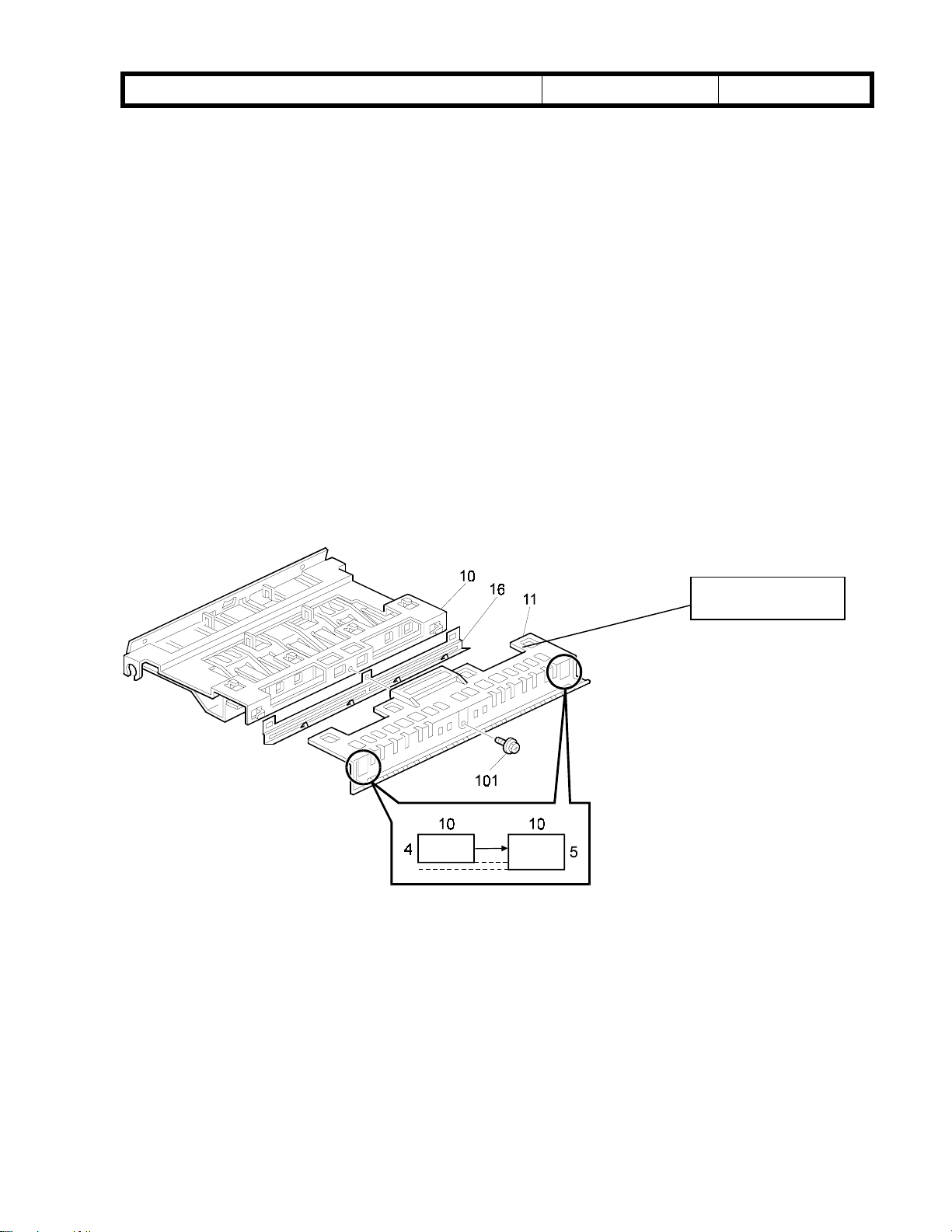
Temporary countermeasure applied from December 1999 production:
The screws for attaching the right lower fusing stay (#10:A2944059) and the rear fusing
plate (#15: A2944057) have been inserted from the front side. They were previously
inserted from the rear side.
Permanent countermeasure for machines in production:
The screw holes in the rear fusing plate have been changed from 4.1 ± 0.1 mm and
4.1 ± 0.1 x 6 mm to 4 mm. The screw holes in the right lower fusing stay have been
changed from 4 mm to 4.1 ± 0.1 mm and 4.1 ± 0.1 x 6 mm. Please note that for the
permanent countermeasure, the insertion direction of the screws for the right lower fusing
stay and rear fusing plate is unchanged (i.e. from the rear side).
The right lower fusing stay and rear fusing plate will be given new part numbers (see
below). The interchangeability between old and new parts is O/O as a set. Detailed parts
Page 12

T
echnical
B
ulletin
PAGE: 3/3
Model:
information will be announced in an MB when the cut-in serial numbers are available.
P/N change:
-Right lower fusing stay: P/N changed from A2944059 to A2944099.
-Rear fusing plate: P/N changed from A2944057 to A2944094.
Action in the field for machines produced before December 1999:
If this symptom occurs on machines with the following serial numbers, please insert the
screws from the front instead of the rear side. Refer to the temporary countermeasure on
the previous page.
A29414,24; L0659110XXX, A29426: 4B11190XXX, A29415,17,22,27; H369110XXX
Bellini
Date:
31-Jan-00
No.:
RA294004
Page 13
RICOH Technical
Bulletin
PAGE: 1/3
Model:
Subject:
From:
Bellini
Key Counter Extension Kit & Relay Key Counter
Harness
Technical Services Dept., GTS Division
Classification:
Troubleshooting
Mechanical
Paper path
Other ( )
Date:
Prepared by:
Part information
Electrical
Transmit/receive
03-Feb-00
Action required
Service manual revision
Retrofit information
No.:
RA294005
Hiroki Kobayashi
Part Number of the Key Counter Extension Kit
The part number for the extension cable is not listed in the parts catalogue or service
manual. This cable is required when installing the key counter together with the LCT, and
can be ordered as a spare part. For the installation procedure, please refer to page 3-27 of
the service manual.
The part number is as follows:
Old part
number
New part
Description Q’ty
number
A2949501 Key Counter Extension Kit
1
Key Counter Relay Harness - (Lanier Version Only)
Per Lanier's request, the Key Counter Relay Harness has been connected to the copier
key counter harness in production machines. This harness will allow the Lanier key
counter to be installed in the copier. Regarding the cut-in serial numbers, we will issue an
MB as soon as they are available.
#: New index in the parts catalog
Old part
number
A0965464 Key Counter Connector
New part
number
A2945496
A2945497
Description Q’ty Int Page Index Note
Key Counter Relay Harness
- Lanier
Key Counter Short
Connector - 4P
0 - 1
0 - 1
1 - 0
47 #27
47 #28
47 23
Page 14
RICOH Technical
Bulletin
PAGE: 2/3
Model:
Bellini
[A]
Date:
#28: Key Counter Short
Connector.
Ricoh: A0965464
Lanier: A2945497
#28: Key Counter Short Connector.
Lanier: A2945497
03-Feb-00
No.:
RA294005
A2945496
#27: Key Counter Relay Harness.
This part includes the short connector
(A2945497).
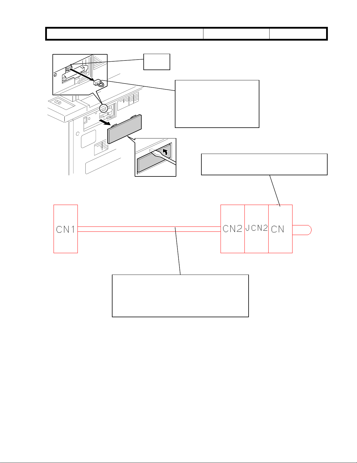
CN1 has been connected to connector [A] of the copier harness (A2945098: SICU
Connect Harness). The service manual procedure for key counter installation has not been
changed. Because the key counter relay harness reverses the orientation of the four
harness cables, it is not necessary to add additional key counter relay harnesses to the
LCT (even if the optional LCT is installed).
In addition, the service manual procedure for key counter installation with the LCT remains
unchanged. (Key counter extension kit <A2949501> on page 1/3 is required.)
Page 15

RICOH Technical
Bulletin
PAGE: 3/3
Model:
Note on attaching the new key counter relay harness in Lanier machines:
Do not install key counters for Ricoh copiers in Lanier copiers. This may damage the ICs
on the BICU board.
Do not connect the Ricoh short connector (A0965464: Key Counter Connector) to Lanier
copiers. This may also damage the ICs on the BICU board.
Bellini
Date:
03-Feb-00
No.:
RA294005
Page 16
T
echnical
B
ulletin
PAGE: 1/2
Model:
Subject:
From:
Bellini
Manual Correction
Technical Services Dept., GTS Division
Classification:
Troubleshooting
Mechanical
Paper path
Other ( )
Part information
Electrical
Transmit/receive
Date:
15-Feb-00
Prepared by:
J. Mochizuki
Action required
Service manual revision
Retrofit information
Please correct your Bellini service manuals as follows:
Location: Incorrect description: Correct description: Note:
Page 1-2
Toner Yield:
Page 1-8
Item 3
Page 1-8
55k copies 53k copies
3. Tray 3 (1,500-sheet
LCT)
4. Tray 2 (550-sheet) 4. Tray 2 (500-sheet)
3. Tray 3 (500-sheet)
No.:
RA294006
Item 4
Page 2-105
Last paragraph,
second sentence.
Page 3-11
Step 33-3
Page 3-11
Step 39 Note
Page 4-17
SP2-301-3
Page 4-37
SP4-903-84, 85
“Setting” Column
Page 4-38
SP4-904-5
400K 300K The yield of the oil
supply cleaning web is
300K.
Hold down the clear/stop
key
Perform SP6-009 (DF
Free Run)
If the user normally feeds
thicker paper from the
by-pass tray, use a
higher setting.
0 ∼ 5
1/step
2
Please delete this mode from the manual. This mode has been
Hold down the clear key
Perform SP6-008-3 (DF
Output Check)
If the user normally feeds
thicker paper, use a
higher setting.
0 ∼ 2
1/step
2
Using SP6-008-3
makes it easier to
remove dust.
removed from the first
production lot.
Page 4-42
SP5-038
“Setting” Column
0: No
1: Yes
The default setting was
missing.
Page 17
T
echnical
ulletin
B
PAGE: 2/2
Model:
Page 4-47
SP6-116
“Function”
Column
Page 7-31
Page 2-80
Bellini
Incorrect
Paper Size
Switch
00111 A3-L 11" x 17"-L
00011 8
10011 A4-L 8
01001 A4-S 8
00100 8
00010 — 8" x 10"-S
00001 A5-S 8" x 10"-L
10000 8 k-L (Taiwan version only) 8" x 13"-L
11000 16 k-L (Taiwan version only) 10" x 14"-L
11100 16 k-S (Taiwan version only) 11" x 15"-L
11110
Date:
Multiply
by this number to
determine the staple limit
number for thick paper
mode.
SC735: Finisher Exit
Guide Error
Paper size switch and paper size (see the tables
below)
the normal limit
A4/A3 Version LT/DLT Version
" x 13" 8
1/4
" x 13" 5
1/2
✻✻
Divide
by this number to
determine the staple limit
number for thick paper
mode.
SC736: Finisher Exit
Guide Error
the normal limit
Paper Size
15-Feb-00
1/2
1/2
1/2
1/2
" x 14"-L
" x 11"-L
" x 11"-S
" x 8
1/2
"-S
No.:
RA294006
Correct
Paper Size
Paper Size
Switch
01111
00111
10011 A4-L 8
01001 A4-S 8
00100 8
00010
00001 A5-S
10000 8 k-L (Taiwan version only)
11000 16 k-L (Taiwan version only)
11100 16 k-S (Taiwan version only)
11110
A4/A3 Version LT/DLT Version
A3-L 11" x 17"-L
8
" x 13" 8
1/4
" x 13" 5
1/2
A5-L
✻✻
" x 14"-L
1/2
" x 11"-L
1/2
" x 11"-S
1/2
" x 8
1/2
5
1/2
8" x 10
8" x 10"-L
8" x 13"-L
10" x 14"-L
" x 8
1/2
1/2
1/2
"-L
"-S
"-L
Page 18
RICOH Technical
Reissued: 16-Mar-00
Bulletin
PAGE: 1/
5
Model:
Bellini
Date:
15-Dec-99
No.:
RA294001a
RTB Correction
The items in bold italics have been corrected added.
Subject:
From:
Classification:
While SP2-207-2 (Toner Bank Toner Supply) is performed at installation, the rotation of
the toner hopper gear (AB013748: Joint Gear -15Z) may cause an oversupply of toner
from the hopper to the development unit. This in turn causes relatively high image density
in copies/printouts made just following installation. To correct this, machines in massproduction have been modi fied as fol lows:
Toner Hopper Gear Replcement at Installation
Technical Services Dept., GTS Division
Troubleshooting
Mechanical
Paper path
Other ( )
Part information
Electrical
Transmit/receive
Prepared by:
Action required
Service manual revision
Retrofit information
H.K.
Temporary Solution
The toner hopper contains red idler gear (A2943255: Idler Gear - 15Z). This gear reduces
the drive supplied to the toner hopper and prevents the oversupply of toner that occurs in
the initial period following installation.
The toner hopper gear for normal operation (White gear:AB013748: Joint Gear -15Z) and
a spare C-ring (07200060B: Retaining Ring - M6) have been packed in the accessory
plastic bag.
The procedure for the Toner Hopper Drive Gear Replacement (Joint Gear - 15Z) has been
packed in the accessory plastic bag. The procedure is also included on page 2/3 of this
bulletin.
Action required
Replace the red idler gear with the white gear after carrying out SP2-207-2 (Toner Bank
Toner Supply) by referring to the procedure for the Toner Hopper Drive Gear Replacement
(Joint Gear - 15Z) packed in the accessory plastic bag. The red idler gear is not necessary
after machine installation.
Permanent Solution
The permanent solution is basically the same as the temporary solution. To facilitate gear
replacement, the gear has been mounted with a screw (09513006B: Philips Screw With
Flat Washer - M3x6) instead of a C-ring. The procedure is included on page 3/3 of this
bulletin. Regarding the cut-in serial numbers for this modification, we will issue an MB as
soon as they are available.
Action required
Same as “Action required” described above.
Page 19
RICOH Technical
Reissued: 16-Mar-00
Bulletin
PAGE: 2/
5
Model:
The part number of the toner hopper unit will be changed from #A2943200 to a new part
number due to the above modificati o n.
field, perform SP2-207-2 using the red gear because the new toner hopper does not
contain any toner.
The toner hopper unit part number will therefore be changed because of the gear
replacement and C-ring substitution.
#A2943200 contains a white gear, this gear should be changed to the red gear when
installing A2943200 in machines already in the field. After performing SP2-207-2
with the red gear, it is necessary to reinstall the white gear.
The following is the procedure packed in the accessory plastic bag as the temporary
solution. After step #35, remove the development unit and follow the procedure labeled
(*)
Bellini
below.
When replacing the toner hopper unit in the
Please be aware that although the spare part
Then, put back the development unit.
Date:
15-Dec-99
No.:
RA294001a
Toner Hopper Drive Gear (Joint Gear 15Z) Replacement
Please add the gear replacement procedure (*) after step #35 (Toner Bank Toner Supply).
#35. Supply toner from the toner bank to the toner hopper as follows:
1) Select SP2-207-2(To ner Bank To ner Suppl y )
2) Press the “Start key” on the LCD.
# *
#36. Change the paper size for all paper trays to suit the customer’s request.
Remove the Joint Gear 15Z that has been marked red [A].
*
Replace it with the white gear [B] and a spare C-ring packed in the accessory
plastic bag.
B
A
Toner Hopper Unit Rear View
Page 20
RICOH Technical
Reissued: 16-Mar-00
Bulletin
PAGE: 3/
5
Model:
The following is the procedure packed in the accessory plastic bag as the permanent
solution. After step #35, remove the development unit and follow the instruction marked
with an asterisk (*). Then, put back the developme nt uni t.
Bellini
Date:
15-Dec-99
No.:
RA294001a
Toner Hopper Dr ive Gear (Joint Gear 15Z) Replacement
Please add the gear replacement procedure after step #35 (Toner Bank Toner Supply).
#35. Supply toner from the toner bank to the toner hopper as follows:
1) Select SP2-207-2 (Toner Bank Toner Supply)
2) Press the “Start” key on the LCD.
*:
#36. Change the paper size for all paper trays to suit the customer’s request.
*
Remove the Joint Gear 15Z that has been marked red [A].
Replace it with the white gear [B] packed in the accessory plastic bag.
B
A
Toner Hopper Unit Rear View
Page 21

RICOH Technical
Reissued: 16-Mar-00
Bulletin
PAGE: 4/
5
Model:
Please make note of the following necessary actions following each service activity
listed below:
Service activity Necessary action for
Developer replacement No further action is
Toner Hopper Unit
Replacement (empty toner
hopper installation).
Toner transport tube
cleaning (before and after
machine transportation).
Bellini
adding toner to the toner
hopper:
required. The white gear is
in the toner hopper unit.
* Refer to the procedures
described above in this
bulletin.
No further action is
required. The white gear is
in the toner hopper unit.
Date:
15-Dec-99
Remarks:
Toner can be supplied
from the toner hopper.
Toner is not in the toner
hopper. If the above action
is not carried out, SC495
will be displayed.
Toner is already inside the
development unit and
toner hopper.
No.:
RA294001a
Note for SP2-207-2
Occasionally, SP2-207-2 finishes within 2 seconds or so. If this happens, perform
SP2-207-2 again. Normally this mode will continue for about 5 minutes.
Reason
The mylar attached to the agitator in the toner hopper cleans the surface of the
toner hopper sensor. This is done so that the sensor will accurately detect the
amount of toner in the hopper. If the sensor detects toner in the hopper when SP2207-2 is initiated, the SP mode will not be carried out. This is to prevent toner from
being mistakenly supplied. However, when the mylar is rotated to clean the sensor
surface, the sensor may sometimes detect the mylar and judge that there is still
toner present. This may occur even if there is no toner in the hopper.
Page 22
RICOH Technical
Reissued: 16-Mar-00
Bulletin
PAGE: 5/
5
Model:
Bellini
Correction for service manual page 4-15
Please correct your service manual as follows:
Incorrect: 7 minutes
Correct : 5 minutes
2-207
Forced Toner Supply
1 Forced Toner
Supply
2 Toner Bank
Toner Setup
Forces toner supply for 7 seconds from
the toner bank through the toner hopper
to the development unit.
This mode finishes automatically after
the toner is supplied 7 times (1 s for
each time).
Turns on the main motor, development
motor, development bias, toner supply
motor and charge corona. Then turns on
the toner supply coil clutch to supply
toner to the toner hopper, but not to the
development unit. It takes about 5
minutes.
This mode should be used to fill the
toner transport path with toner after
cleaning the toner supply unit, or at
installation.
Date:
15-Dec-99
Start
Start
No.:
RA294001a
Page 23
RICOH Technical
g
g
Bulletin
PAGE: 1/2
Model:
Subject:
From:
Bellini
SP2506
Technical Services Dept., GTS Division
Classification:
Troubleshooting
Mechanical
Paper path
Other ( )
Date:
Prepared by:
Part information
Electrical
Transmit/receive
16-Mar-00
Action required
Service manual revision
Retrofit information
H.K.
No.:
RA294007
SYMPTOM
In the Japanese market, it has been reported that vertical black lines have a tendency to
appear in copy images after long continuous copy jobs (10 hours).
CAUSE
Toner is not completely removed by the cleaning blade due to paper dust that accumulates
on the cleaning blade after long continuous copying. During the continuous copying, the
drum motor does not stop and turn in reverse to clean the edge of the cleaning blade.
SOLUTION
On the production line (from March production: SICU&BCU version
The default settings of SP2506-1 and -2 will be changed from March production so that the
drum motor stops and turns in reverse every 30 minutes during continuous copying to
clean the blade edge.
Default setting: 2506-1 (changed from No to
minutes
).
Yes
), 2506-2 (changed from 15 to
Here is the revised SP Mode table:
2-506
Cleaning Interval – Multiple Copy
1On/Off
2 Interval
Selects whether multiple copy jobs are
stopped at re
purposes:
1. Stop and turn the drum motor in reverse
to clean the cleaning blade edge.
B
2. Make an ID sensor pattern to correct the
toner density control.
The interval is determined by SP2-506-2.
Use if the drum gets dirty or images get too
pale or too dark during long copy jobs.
Selects the interval at which m u lti copy jobs
B
are stopped for blade cleaning.
ular intervals for the followin
V.7.28.1)
30
1: No
2: Yes
1 ~ 100
1 minute/step
30 minutes
Page 24

RICOH Technical
Bulletin
PAGE: 2/2
Model:
Countermeasure in the field for machines produced up to February 2000:
Upgrade the SICU & BCU to V.7.28.1. Then, change the SP mode values as shown above
if the same symptom appears in the field.
Please note:
SP2-506-1 and –2
In order to activate the new default settings after you have installed the firmware, you must
enter the SP modes and manually change the settings to these new default values. After
this has been done, the machine will recognize these settings as the defaults.
If you change these two SP mode settings with versions older than 7.28.1, SC990 may
occur when printing out blank copies with the slip-sheet, cover sheet or chapter sheet
functions. Therefore, we recommend that you update the firmware to version V.7.28.1.
Continuous copy runs
Continuous copy runs are stopped for 5 or 6 seconds every 30 minutes to clean the edge
of the cleaning blade. However, the fusing unit maintains the ready temperature, as the
machine’s major internal mechanisms are not shut down during this interval.
Bellini
Date:
16-Mar-00
No.:
RA294007
Page 25
RICOH Technical
Bulletin
PAGE: 1/3
Model:
Subject:
From:
Bellini
Dog Ear
Technical Services Dept., GTS Division
Classification:
Troubleshooting
Mechanical
Paper path
Other ( )
Date:
Prepared by:
Part information
Electrical
Transmit/receive
21-Mar-00
Action required
Service manual revision
Retrofit information
H.K.
No.:
RA294008
Symptom 1:
Dog ear at the rear side of the leading edge.
Cause:
The Fusing Exit Guide is not properly set. There is a small gap at the Rear Magnet Catch.
In addition, the hot roller strippers are not in the proper position when the exit guide is
closed due to the mechanical load of the stripper sliding mechanism.
Solution:
Temporary Solution: From December production.
In order to minimize the sliding mechanical load, apply grease to the Stripper Release
Slider in the following places:
- The 2 shoulder screw holes on the Guide Plate
- The 5 projections on the surface of the Exit Guide Bracket
Fusing Exit Guide
x
x
x
x
x
Guide Plate
Screw Holes
Exit Guide
Bracket
X: Projection
Page 26
RICOH Technical
Bulletin
PAGE: 2/3
Model:
Type of grease: Grease Barrierta –JFE5 5/2 (P/N: A028 9300)
Permanent Solution: From March production.
In addition to applying grease to the stripper release slider, the shape of the Exit Guide
Plate has been modified to smooth the stripper sliding mechanism as an "improvement".
The part number is still the same.
Bellini
Date:
21-Mar-00
No.:
RA294008
Symptom 2:
Dog-ears have a tendency to occur when using curled paper.
Solution:
Temporary Solution:
To minimize this, the following modification has been applied to machines in mass
production:
The height of the holes has been changed from 4 x 10 mm to 5 x 10 mm, so the position of
the entrance guide has been raised by 1 mm on the production line.
Cut-in serial numbers
A294-14 L065003XXXX
A294-15 H3600200180
A294-17 H3600200220
A294-22 H3600200001
Entrance Guide
A294-24 L065003XXXX
A294-26 4B10200001
A294-27 H3600200051
Page 27

RICOH Technical
Bulletin
PAGE: 3/3
Model:
Permanent Solution: From March production
Refer to Bellini MB No. 4 for details.
Bellini
Date:
21-Mar-00
No.:
RA294008
Page 28

!"#$% T
echnical Bulletin
PAGE: 1/2
Model:
Subject:
From:
Bellini
Timing Belt Slipping Off
Technical Services Dept., GTS Division
Classification:
Troubleshooting
Mechanical
Paper path
Other ( )
Part information
Electrical
Transmit/receive
Date:
24-Apr-00
Prepared by:
H.K.
Action required
Service manual revision
Retrofit information
SYMPTOM
No paper feed from trays 2 and 3.
CAUSE
During rotation, the lower timing belt may tend to slip off the idler pulley.
SOLUTION
- Production line -
No.:
RA294009
A spacer (AA132212: Spacer – 8 x 22 x 1.5) will be added as a flange to prevent the belt
from slipping off the pulley. In addition, the orientation of the pulley (AB032716) will be
reversed.
This modification will be applied from May 2000 production.
- In the field -
If the problem occurs in the field, install the spacer as a flange and reverse the orientation
of the pulley.
Page 29
!"#$% T
echnical Bulletin
PAGE: 2/2
Model:
Bellini
[C]
[A]
[B]
[D]
Date:
24-Apr-00
[E]Reverse the pulley [D].
No.:
RA294009
A294R930.WMF
Spacer Installation for the Lower Timing Belt (2nd & 3rd Trays)
1. Turn off the main switch.
2. Remove the lower rear cover.
3. Remove the PSU (5 screws, all connectors) and IOB board (4 screws, all connectors).
See Boards and Other Items in the service manual.
4. Remove the tension spring [A].
5. Remove the screw [B].
6. Remove the lower timing belt [C].
7. Remove the pulley [D] (1 E-ring).
8. Attach the spacer [E].
9. Reverse the pulley [D] and attach it as shown (1 E-ring).
10. Put back all removed parts.
Page 30

!"#$% T
echnical Bulletin
PAGE: 1/3
Model:
Subject:
From:
Bellini
Toner bottle cap open/close mechanism faliure
Technical Services Dept., GTS Division
Classification:
Troubleshooting
Mechanical
Paper path
Other ( )
Part information
Electrical
Transmit/receive
Date:
01-May-00
Prepared by:
No.:
RA294010
H.K.
Action required
Service manual revision
Retrofit information
SYMPTOM
The open/close mechanism for the lower toner bottle cap does not work properly. In some
cases, the mechanism does not return the cap to the bottle, which causes the toner to spill
when the bottle is removed.
Note: This symptom occurs only with the lower toner bottle.
Occurrence conditions:
1. The lower toner bottle is not placed in the toner bank unit or the toner end
condition is detected for the lower toner bottle and:
2. The upper toner bottle is shaken several times before it is set.
CAUSE
If an operator shakes the bottle several times and then sets it in the machine, too much
toner will be supplied from the bottle. Normally, when the bottle cap is opened, about 30 to
40 g of toner is supplied. However, after the bottle has been shaken several times, this
amount can be up to 150 g.
In addition, if the upper bottle is installed first after having been shaken several times,
toner can get jammed in the lower bottle open/close mechanism, causing the mechanism
to lock.
SOLUTION
Production line (from April production: SICU&BCU version V.7.31.3)
-Software modification: If the upper toner bottle is set first, the machine LCD will instruct
the operator to install the lower toner bottle first.
-Decal: A caution decal [A] (A2941273) has been attached to the toner bank cover. Also,
step 3 of the existing toner bank decal [B] has been changed. This decal is attached to the
inner face of the toner bank cover.
The decal will read:
Do not shake toner bottle before setting.
Set lower toner bottle first.
Page 31

!"#$% T
echnical Bulletin
PAGE: 2/3
Model:
Bellini
Date:
01-May-00
No.:
RA294010
Countermeasure in the field for machines produced up to March 2000:
Update the SICU & BCU to V.7.31.3. Demonstrate to the customer the correct way to
install the toner bottles (according to the decal illustrations).
[A]
A2941273
CAUTION
DECAL - TONER
SUPPLY
2
1
1
2
Toner Bank Decal [B] (A2941272)
Page 32

!"#$% T
echnical Bulletin
PAGE: 3/3
Model:
NOTE:
Toner Bank Decal [B] (A2941272): The part number remains the same. The old decal has
never been supplied from SPC as a service part.
Bellini
Toner Bank Cover
Existing Toner Bank Decal [B] on the inner face
of the toner bank cover
Toner Bank Inner faceplate
Date:
01-May-00
No.:
RA294010
Page 33

!"#$% T
echnical Bulletin
PAGE: 1/7
Model:
Subject:
From:
Bellini
Used toner bottle full at an early stage
Technical Services Dept., GTS Division
Classification:
Troubleshooting
Mechanical
Paper path
Other ( )
Part information
Electrical
Transmit/receive
Date:
26-May-00
Prepared by:
No.:
RA294011
S. Hizen
Action required
Service manual revision
Retrofit information
SYMPTOM
Used toner bottle at an early stage.
Almost all of the toner that should be routed to the toner collection unit is sent to the used
toner bottle.
This is because the old-type toner collection pipe was installed in the following machines.
A294-17: H3691100001 to H3691100015 (15 machines)
A294-27: H3691100039 to H3691100053 (15 machines)
COUNTERMEASURE
Replace the toner collection pipe
Please refer to following toner collection unit removal and installation procedures.
Note: Before beginning the replacement procedure, please check whether the pipe in the
machine is the old type.
1. Toner Collection Unit Removal Procedure
Preparation:
1) Remove the upper rear cover.
2) Remove the drum inner cover and drum
stay. Slide the drum unit out 50 mm.
(Picture 1)
Picture 1
Page 34

!"#$% T
echnical Bulletin
PAGE: 2/7
Model:
Removing the Toner Collection Unit:
1) Remove the fly wheel (3 screws).
2) Remove the 4 BCU securing screws and
tilt out the BCU toward you.
(Picture 2)
3) Remove the BCU hinge brackets
(one on each side, one screw each).
The picture shows the right bracket
being removed.
(Picture 3)
Bellini
Date:
Picture 2
Picture 3
26-May-00
No.:
RA294011
4. Disconnect the three fusing unit
connectors and ground wire (1 screw).
These 3 harnesses run above the pipe.
(Picture 4)
Picture 4
Page 35

!"#$% T
echnical Bulletin
PAGE: 3/7
Model:
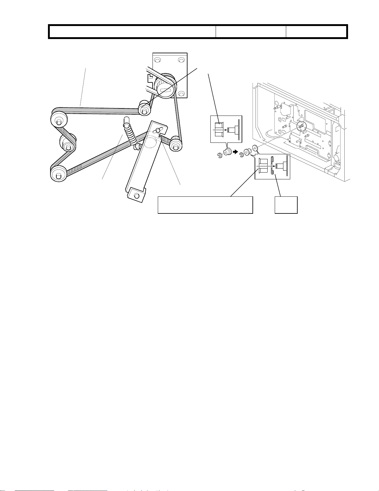
5. As shown in the picture to the right, remove the
support plate located near the main motor
(1 screw), loosen the 2 screws of the
tightener bracket and remove the tightener
tension spring.
Next, remove the three timing belts as shown
in the two pictures below.
(Pictures 5, 6)
Bellini
Date:
Picture 5
Picture 6
26-May-00
No.:
RA294011
6. Remove the exhaust fan duct, located to
the left of the main motor (no screws).
Note: It is easier to remove the duct
if you loosen the fan bracket securing screw
first. This screw is located to the left of the
duct.
(Picture 7)
Picture 7
Page 36

!"#$% T
echnical Bulletin
PAGE: 4/7
Model:
7. Remove the main motor (4 screws)
and remove the two connectors.
Note: Tilt the bottom face of the motor
toward you when removing it from
the machine.
(Picture 8)
8. Remove the 2 securing screws for the
collection case.
(Picture 9)
Bellini
Date:
Picture 8
Picture 9
26-May-00
No.:
RA294011
9. Remove the screw for the distribution case
(the only M4X10 screw).
(Picture 10)
Picture 10
Page 37

!"#$% T
echnical Bulletin
PAGE: 5/7
Model:
10. Slide the toner collection unit to the right,
disconnect the screw drive shaft from
the bushing and remove the unit.
(Picture 11)
11. The picture below is the toner collection
unit after it has been removed.
(Picture 12)
Bellini
Date:
Picture 11
Picture 12
26-May-00
No.:
RA294011
Page 38

!"#$% T
echnical Bulletin
PAGE: 6/7
Model:
Bellini
Date:
26-May-00
No.:
RA294011
2. Toner Collection Pipe Replacement Procedure
How to distinguish the old type from the current type:
The angles of the cut-outs are 60 degrees different.
1. Remove the two gears shown in the picture (2 e-rings).
2. Remove the 2 pipes from the distribution case.
3. Loosen the two screws of the collection case and remove the lower pipe only.
Note: Place a sheet of paper or newspaper underneath the case, as toner from the pipe
will tend to leak.
4. Replace the lower pipe with the current type.
Note: Make sure that the toner drop hole is facing downward. However, it does not need
to be completely vertical (90 degrees). In addition, make sure that the U-groove on
the left face of the pipe is properly lined up with the projection on the case.
5. Return all other parts to their original positions.
Note: Make sure that the toner drop hole is in a lower position.
(It would be hard to see the hole from the front when the hole is in the proper position)
NOTE: After installing the new pipe, please double check that the drop hole is facing
downward. You can check this by looking at the pipe from the front. If you can barely see
the hole, it is in the proper position.
Picture 13
Page 39

!"#$% T
echnical Bulletin
PAGE: 7/7
Model:
Bellini
Date:
26-May-00
No.:
RA294011
3. Toner Collection Unit Installation Procedure
Reinstall the parts in the reverse order in which they were removed (see the unit Removal
Procedure above).
Note: Please follow the procedure below when reinstalling the 3 Timing Belts (step 5):
1. Attach the support plate (see picture below).
2. Attach the belts.
3. Turn the belts several times in the motor rotation direction.
4. Tighten the 2 screws of the tightener bracket.
Picture 14
Page 40

echnical Bulletin
T
PAGE: 1/16
Model:
Subject:
From:
Bellini
105 CPM Version Information
Technical Services Dept., GTS Division
Classification:
Troubleshooting
Mechanical
Paper path
Other ( )
Part information
Electrical
Transmit/receive
Date:
26-May-00
Prepared by:
No.:
RA294012
H.K.
Action required
Service manual revision
Retrofit information
Introduction
To facilitate servicing the 105cpm (A295) model in the field, this RTB describes the
differences from the 85cpm (A294) model.
Major Parts
Fusing Lamps:
85 CPM AX430052 Fusing Lamp – 230V/530W
105 CPM AX430055 Fusing Lamp – 230V/630W
The wattage of the fusing lamps has been increased from 530 to 630W to improve fusing.
To distinguish these two lamps, the colors of the front harnesses [A] are as follows:
530W: Blue
630W: Red
The connectors for both the lamps have the same color. The following note for reassembly has not been changed:
[A]
Note on 6-87
At the front, connect the white fusing lamp connectors to the white connectors on the
cable. At the rear, connect the green fusing lamp connectors to the green connectors on
the cable.
Page 41

echnical Bulletin
T
PAGE: 2/16
Model:
Bellini
Date:
26-May-00
No.:
RA294012
Fusing Lamp Control:
The fusing temperature control for the 105cpm model is different from that of the 85cpm
model.
188°C (A4/LT width or less) (85cpm)
198°C (A4/LT width or less) (105cpm)
183°C (Larger than A4/LT width) (85cpm)
193°C (Larger than A4/LT width) (105cpm)
➀
: Main switch on
➁
: Process control data initialization
and idling begins.
➂
: Idling ends
➃
: Stand-by
➄
: Copying begins
155°C
177°C
173°C(85cpm)
178°C(105cpm)
➁➂ ➃➀➄
A294D627.WMF
The CPU turns on all three fusing lamps after the main switch is turned on, with a
one-second interval between each. This prevents the power from the AC line from
dropping too quickly.
When the fusing temperature reaches 155°C, the machine starts the process control data
initialization. However, this is not performed if the fusing temperature is already above
100°C at the time the main switch is turned on.
When the fusing temperature reaches 155°C, the copier starts fusing idling. However, the
idling is not performed if the fusing temperature is already above 100°C at the time the
main switch is turned on
When the temperature reaches 177°C, the warm-up period is completed and the “Ready”
indicator turns on. After this, the machine maintains a fusing temperature of 173°C (85
cpm model) and 178°°°°C (105cpm model).
In stand-by mode, one of the fusing lamps turns on intermittently in order to maintain ready
temperature. During the copy cycle, all three fusing lamps are used to maintain operating
temperature. The machine will turn the lamps on one at a time, with a one-second interval
between each.
Page 42

echnical Bulletin
T
PAGE: 3/16
Model:
The CPU changes the interval that the fusing lamp is on depending on the temperature
measured by the thermistor. This is to maintain the fusing temperature as close to the
target value as possible.
Even if one of the lamps fails during copying, the machine will continue to function.
However, if it detects a broken lamp just after being switched on, an SC error occurs and
copying is not possible.
The machine uses the fusing lamp on/off control mode to maintain the fusing temperature
as close to the target value as possible. Even if thick paper mode is selected, fusing
temperature control does not change.
SP1-902-2 Default setting (42 seconds: 85 cpm, 34 seconds: 105 cpm):
Page 2-105, second paragraph:
Every 42 seconds (85cpm) or 34 seconds (105cpm) during printing, the oil
supply/cleaning web motor turns for 0.8 seconds to move the oil supply and cleaning web
felt. This 42 or 34-second cycle starts when the first copy reaches the fusing exit sensor
and ends 2 seconds after the last copy has passed this sensor. Both the motor rotation
cycle and on-time are adjusted by SP1-902-2 / 3.
Bellini
Date:
26-May-00
No.:
RA294012
Hard Disk:
85 CPM A6915879 Hard Disk Drive
105 CPM A2955172 Hard Disk - Fireball Plus KX
For printing out with the 105 cpm model, it is necessary to use a hard disk with a faster
rotation speed in order to conform to the higher copy speed of the machine. The hard
disks used for both models are as follows:
Seek Time Rotation
Velocity
85cpm 9.5 ms 5400 rpm 4.3 GB
105cpm 8.5 ms 7200 rpm 6.8 GB
Capacity
Page 43

echnical Bulletin
T
PAGE: 4/16
Model:
Bellini
HDD Control (S/M 2-127):
UP Setting for
“Memory Allocation”
Copier Priority Copy Jobs: 0.82 GB
Copy Server Jobs:
3.08 GB (85 CPM)
5.00 GB (105 CPM)
Printer Jobs: 0.20 GB
Max. Memory for Document
Server
Copy Jobs: 1.23 GB
Copy Server Jobs:
2.57 GB (85 CPM)
5.00 GB (105 CPM)
Printer Jobs: 0.31 GB
HDD 1 (Front) HDD 2 (Rear)
Date:
26-May-00
Copy Jobs: 3.35 GB
Copy Server Jobs: Not used
Printer Jobs: 0.76 GB
Copy Jobs: 1.23 GB
Copy Server Jobs:
2.57 GB (85 CPM)
5.00 GB (105 CPM)
Printer Jobs: 0.31 GB
No.:
RA294012
Page 44

echnical Bulletin
T
PAGE: 5/16
Model:
Transfer Belt:
To achieve a higher copy speed than the 85cpm model, the transfer belt in the 105cpm
model is given a higher transfer current. With higher transfer current, black lines have a
greater tendency to appear in half-tone areas on the copy. To compensate for this, the
transfer belt used in the 105cpm model has a lower resistance.
To distinguish between the two transfer belt units, a seal is attached to the transfer belt
frame for the 105cpm model as shown. Note that the belt for the 105cpm model can also
be used for the 85cpm model.
Bellini
A229 3852 Transfer Belt85 CPM
A2943810 Transfer Belt Unit
A229 3899 Transfer Belt105 CPM
A2953810 Transfer Belt Unit
Date:
Seal
26-May-00
No.:
RA294012
Transfer Belt Frame
Page 45

echnical Bulletin
T
PAGE: 6/16
Model:
Bellini
Date:
26-May-00
No.:
RA294012
Specifications
The additional items added to the specifications of the 105cpm model are listed on page
7/16 of this bulletin.
SP Mode
The SP modes that have been revised or added for the 105cpm model are listed on page
11/16 of this bulletin. All information from Class 1 of the 85cpm model is also listed along
with these new additions/revisions.
Unique parts
An MB for information on the 105cpm model will be issued containing a list of the parts
that are unique to this model.
Input Voltage Level:
The input voltage for the 85cpm model listed on page 3-2 of the Service Manual is
incorrect. Please correct your manuals as follows:
North America:
240V, 60 Hz: More than 10A (85cpm)
240V, 60 Hz: More than 12A (105cpm)
Europe/Asia:
220 ~240V, 50/60 Hz: More than 10A (85cpm)
220 ~240V, 50/60 Hz: More than 12A (105cpm)
Finisher ROM interchangeability
Although the finisher itself is interchangeable between both the 85cpm and 105cpm
models, the EPROM firmware must be updated to version E or newer for fnishers
produced before April 2000. The cut-in serial numbers for April 2000 production are as
follows:
L0670040001 (B302-14)
H3800400001 (B302-17)
4B20400001 (B302-26)
Page 46

echnical Bulletin
T
PAGE: 7/16
Model:
Bellini
Date:
26-May-00
OVERALL MACHINE INFORMATION
SPECIFICATIONS
COPIER ENGINE
Configuration: Console
Copy Process: Dry electrostatic transfer system
Originals: Sheet/Book
Original Size: Maximum: A3/11" x 17"
Minimum: A5, 5
Original Alignment: Rear left corner
Paper Size/Weight:
Size: Mainframe, Tray 1 (Tandem Tray):
A4 sideways and LT sideways
Mainframe, Trays 2 and 3 (Universal Trays):
Europe/Asia:
N. America:
lengthwise
LCT, Trays 4 ~ 6:
A4 sideways, B5 sideways, LT sideways, A5,
HLT
Duplex Tray: A5/HLT (lengthwise or sideways)
1/2
"x 8
" (using ADF)
1/2
A5 - A3 lengthwise,
8-kai sideways, 16-kai
5
1/2
" x 8
" sideways - 11" x 17"
1/2
to A3/DLT. Tab paper cannot be used.
No.:
RA294012
Weight: Mainframe, Trays 1 to 3:
52 to 163 g/m
2
16 to 40 lbs Bond
50 to 60 lbs Cover
90 lbs Index (no Tab)
LCT, Trays 4 and 5:
52 to 216 g/m
2
16 to 40 lbs Bond
50 to 80 lbs Cover
90 to 110 lbs Index
LCT, Tray 6:
Same as Mainframe, Trays 1 to 3
Duplex Tray:
64 to 163 g/m
2
20 to 40 lbs Bond
50 to 60 lbs Cover
90 lbs Index (no Tab)
Page 47

echnical Bulletin
T
PAGE: 8/16
Model:
Bellini
Date:
26-May-00
Reproduction ratios: 7 reduction and 5 enlargement
Metric Version Inch Version
400%
200%
Enlargement
Full Size 100% 100%
Reduction
141%
122%
115%
93%
82%
75%
71%
65%
50%
25%
Zoom: 25 ~ 400%
Copy Speed: 85 cpm: Max. 85 cpm (A4/8
1/2
105 cpm: Max. 105 cpm (A4/8
No.:
400%
200%
155%
129%
121%
93%
85%
78%
73%
65%
50%
25%
" x 11" sideways)
" x 11" sideways)
1/2
RA294012
Resolution: Scanning: 600 dpi
Printing: 600 dpi
Gradation: 256 levels
Warm-up Time: Less than 360 s (from Off mode)
First Copy Time:
(1st Tray, A4 sideways)
Finisher upper tray: face down
85 cpm: Less than 5.4 s
105 cpm: Less than 4.9 s
Finisher upper tray: face up
85 cpm: Less than 4.1 s
105 cpm: Less than 3.8 s
Copier: face down
85 cpm: Less than 4.5 s
105 cpm: Less than 4.2 s
Copier: face up
85 cpm: Less than 3.2 s
105 cpm: Less than 2.9 s
Copy Number Input: Ten-key pad, 1 to 9999
Copy Paper Capacity: 1st Tray: 1,000 sheets (2,000 when used as a tandem
tray)
2nd/3rd Tray: 500 sheets each
4th/5th Tray (LCT): 1,000 sheets each
6th Tray (LCT): 2,550 sheets
Page 48

echnical Bulletin
T
PAGE: 9/16
Model:
Bellini
Date:
26-May-00
Memory Capacity: RAM: 48 MB x 2
HDD: 4.3 GB x 2 (85 CPM), 6.8 GB x2 (105 CPM)
Toner Replenishment: Cartridge exchange (1,450 g/cartridge)
Toner Yield: 53 k copies
(A4 sideways, 6% full black, 1 to 25 copying)
Power Source: North America: 240 V, 60 Hz, 20 A
Europe/Asia: 220 ~ 240 V, 50Hz/60 Hz, 16 A
Power Consumption:
N. America Version
Mainframe Only Full System *
Warm-up about 1.96 kW about 1.98 kW
Stand-by about 0.79 kW about 0.8 kW
Copying about 2.24 kW about 2.3 kW
Maximum less than 2.35 kW less than 2.38 kW
*1: Mainframe with Finisher, Large Capacity Tray
No.:
85 cpm
1
RA294012
Mainframe Only Full System *
Warm-up about 2.51 kW about 2.52 kW
Stand-by about 0.93 kW about 0.95 kW
Copying about 2.67 kW about 2.68 kW
Maximum less than 2.77 kW less than 2.84 kW
*1: Mainframe with Finisher, Large Capacity Tray
Mainframe Only Full System *
Warm-up about 1.89 kW about 1.9 kW
Stand-by about 0.75 kW about 0.77 kW
Copying about 2.14 kW about 2.18 kW
Maximum less than 2.24 kW less than 2.26 kW
*1: Mainframe with the finisher, large capacity tray
Mainframe Only Full System *
Warm-up about 2.38 kW about 2.39 kW
Stand-by about 0.89 kW about 0.9 kW
Copying about 2.52 kW about 2.54 kW
Maximum less than 2.64 kW less than 2.7 kW
*1: Mainframe with Finisher, Large Capacity Tray
105 cpm
1
Europe Version
85 cpm
1
105 cpm
1
Page 49

echnical Bulletin
T
PAGE: 10/16
Model:
Bellini
Date:
26-May-00
Noise Emission *1: 85 cpm
Mainframe Only Complete System *
Warm-up about 74 dB (A) 78 dB (A)
Stand-by about 59 dB (A) 58 dB (A)
Sound Pressure Level *
Mainframe Only Complete System *
During printing 59 dB (A) 68 dB (A)
*1: Actual values in accordance with ISO 7779 standards.
2
: Measured from the position of the bystander or operator during printing.
*
3
*
: Mainframe with all options installed.
Noise Emission *1: 105 cpm
Mainframe Only Complete System *
Warm-up 75 dB (A) 78 dB (A)
Stand-by 59 dB (A) 58 dB (A)
No.:
RA294012
Sound Power Level
3
3
Sound Power Level
3
2
Sound Pressure Level *
Mainframe Only Complete System *
During printing 61 dB (A) 67 dB (A)
*1: Actual values in accordance with ISO 7779 standards.
2
*
: Measured from the position of the bystander or operator during printing.
3
: Mainframe with all options installed.
*
Dimensions:
(W x D x H)
870 x 735 x 1,476 mm (34.3" x 28.9" x 58.1")
(without options)
Weight: 252 kg (without options)
Optional Equipment: Refer to Machine Configuration
2
3
Page 50

26 May 2000 PAGE:10 /16
SERVICE PROGRAM MODE TABLES
NOTE: 1) In the Function column, comments are in italics.
2) In the Settings column, the default value is in bold letters.
3) S and B in the right hand side of the mode number column means that
this mode is stored in the NVRAM on the SICU (S) or BCU (B). If you do
a RAM reset, all these SP modes will be reset to their factory settings.
1-002
Mode No.
(Class 1, 2 and 3)
Side-to-Side Registration
1Tray-1
2Tray-2
3Tray-3
4 Tray-4 (LCT)
5 Tray-5 (LCT)
6 Tray-6 (LCT)
Function Settings
Adjusts the printing side-to-side registration
from the 1st paper feed station using the
trimming area pattern (SP2-902-3, No.15).
B
Use the “
before entering the value.
See “Replacement and Adjustment – Copy
Image Adjustments” for details on SP1-002.
Adjusts the printing side-to-side registration
from the 2nd paper feed station using the
trimming area pattern (SP2-902-3, No.15).
B
Use the “
before entering the value.
The specification is 0
Adjusts the printing side-to-side registration
from the 3rd paper feed station using the
trimming area pattern (SP2-902-3, No.15).
B
Use the “
before entering the value.
The specification is 0
Adjusts the printing side-to-side registration
from the 4th paper feed station using the
trimming area pattern (SP2-902-3, No.15).
B
Use the “
before entering the value.
The specification is 0
Adjusts the printing side-to-side registration
from the 5th paper station using the
trimming area pattern (SP2-902-3, No.15).
B
Use the “
before entering the value.
The specification is 0
Adjusts the printing side-to-side registration
from the 6th paper station using the
trimming area pattern (SP2-902-3, No.15).
Use the “
before entering the value.
B
The specification is 0
•
” key to toggle between + and –
•
” key to toggle between + and –
±
2.0 mm.
•
” key to toggle between + and –
±
2.0 mm.
•
” key to toggle between + and –
±
2.0 mm.
•
” key to toggle between + and –
±
2.0 mm.
•
” key to toggle between + and –
±
2.0 mm.
+9 ~ –9
0.1 mm/step
–1.5 mm
+9 ~ –9
0.1 mm/step
–1.5 mm
+9 ~ –9
0.1 mm/step
–1.5 mm
+9 ~ –9
0.1 mm/step
–2.5 mm
+9 ~ –9
0.1 mm/step
–2.5 mm
+9 ~ –9
0.1 mm/step
–2.5 mm
Page 51

26 May 2000 PAGE:11 /16
1-002
1-003
1-105
Mode No.
(Class 1, 2 and 3)
Side-to-Side Registration
7 Duplex Tray
Paper Buckle Adjustment (Registration)
1 Copier Paper
Tray
LCT Tray
2
3 Duplex Tray B
Duplex Fence Adjustment1-008
Fusing Idling After Low Power Mode1-103
Fusing Temperature Adjustment
1Fusing
Temperature in
Waiting
Condition
2Fusing
Temperature
Lower Limit
Adjusts the printing side-to-side registration
from the duplex tray using the trimming
area pattern (SP2-902-3, No.15).
B
Use the “
before entering the value.
The specification is 0
Adjusts the relay clutch timing at
B
registration. The relay clutch timing
determines the amount of paper buckle at
B
registration. (A positive setting leads to
more buckling.)
Adjusts the distance between the front and
B
rear fences.
Selects whether fusing idling is done or not
B
when recovering from the low power mode.
Adjusts the fusing temperature for standby.
B
Adjusts the fusing temperature lower limit.
When the fusing unit falls below this
temperature, the machine stops copying.
Copying automatically restarts when the
B
fusing temperature recovers.
This SP mode is for designer’s use only.
Function Settings
•
” key to toggle between + and –
±
2.0 mm.
+9 ~ –9
0.1 mm/step
–3.0 mm
+9 ~ –9
1 mm/step
+4.0 mm
+4 ~ –4
0.5 mm/step
0 mm
0: Not done
1: Done
170 ~ 200
1°C/step
173°°°°C
(85 CPM)
178°°°°C
(105CPM)
157 ~ 167
1°C/step
163°°°°C
(85 CPM)
167°°°°C
(105 CPM)
1-902
3Fusing
Temperature
Correction
(<A4/LT)
4Fusing
Temperature
Correction
(A4/LT)
Web Motor Control
1Web
Consumption
2 Web Motor
Drive Interval
Specifies the amount to raise the fusing
temperature from standby mode to print on
B
A4/LT long edge or smaller width paper.
Specifies the amount to raise the fusing
temperature from standby mode to print on
B
paper of A4/LT long edge width.
Displays the percentage of the web
consumption in 1% steps (0% ~ 100%).
B
The value can be manually input using
number keys.
Change the interval of copy operation time
after which the web motor is driven
B
+0 ~ +20
1°C/step
+15°°°°C
+0 ~ +25
1°C/step
+10°°°°C
15 ~ 130
1 s/step
42 s
(85 CPM)
34 s
(105 CPM)
Page 52

26 May 2000 PAGE:12 /16
1-902
2-001
2-201
Mode No.
(Class 1, 2 and 3)
Web Motor Control
Web Motor
3
Drive Time
Web Near End
4
Setting
Changes the time that the web motor is
driven.
B
Changes the web consumption ratio at
which web near end is displayed.
B
About 40k A4 copies can be made after the
web consumption reaches 100%.
Charge Corona Bias Adjustment
1 Image Area
(Auto Process
Control OFF)
Adjusts the voltage applied to the grid plate
during copying when auto process control
is off.
Normally, there is no need to adjust this.
B
If there is an ID or TD sensor problem, the
machine goes into fixed toner supply mode.
After replacing the drum or charge corona
wire, change this value to the default.
2 ID Sensor
Pattern (Auto
Process Control
OFF)
Adjusts the voltage applied to the grid plate
when making the ID sensor pattern, when
auto process control is switched off.
B
Normally, there is no need to adjust this.
If the user wants high density copies, the
sensor pattern must be lighter, so this
voltage must be a higher negative voltage.
Image Area
3
(Auto Process
Control ON)
Adjusts the voltage applied to the grid plate
during copying when auto process control
is switched on.
B
This voltage changes every time auto
process control starts up (every time the
machine is switched on)
4 Grid Voltage for
Transparencies
(OHP)
Adjusts the voltage applied to the grid plate
when translucent mode is selected.
Use this if there is a copy quality problem
B
when making copies on transparencies.
Normally there is no need to adjust this.
See 2-001-1.
Total Corona
5
Current
6 Total Corona
Current (Photo
mode)
D
7V
(Auto Process
Control)
Adjusts the current applied to the charge
corona wire except for Photo mode.
B
Adjusts the current applied to the charge
corona wire for Photo mode.
B
Adjust the target V
Control Initial Setting.
B
Development Bias Adjustment
1 Image Area
Adjusts the development bias for copying.
This can be adjusted as a temporary
B
measure if faint copies appear due to an
aging drum.
Function Settings
0.1 ~ 3.0
0.1 s/step
0.8 s
0 ~ 100
1%/step
100%
–650 ~ –1,300
10 V/step
–1,000 V
–650 ~ –1,300
10 V/step
–800 V
–650 ~ –1,300
10 V/step
–1,000 V
–650 ~ –1,300
10 V/step
–1,070 V
–1,400 ~
–2,800
100 µA/step
–1,400 µµµµA
1,400 ~
–2,800
100 µA/step
–1,600 µµµµA
D
voltage for Process
–900 ~
–1,000
10 V/step
–970 V
–200 ~ –700
10 V/step
–530 V
Page 53

26 May 2000 PAGE:13 /16
2-201
2-209
2-301
2-301
Mode No.
(Class 1, 2 and 3)
Development Bias Adjustment
ID Sensor
2
Pattern
B
Transparencies
3
(OHP)
ID Sensor
4
Development
Potential
B
B
Toner Supply Rate
B
Transfer Current Adjustment
11st Copy Side
B
Transfer Current Adjustment
2 Thick Paper
B
Transparencies
3
(OHP)
B
4 Translucent
Sheet
B
5 2nd Copy
B
Function Settings
Adjusts the development bias for making
the ID sensor pattern for V
SP
measurement.
This should not be used in the field,
because it affects ID sensor pattern
density, which affects toner supply.
Adjusts the development bias for copying
onto transparencies.
Adjusts the development potential for
making the ID sensor pattern for V
SP
measurement.
Do not adjust.
Adjusts the toner supply rate from the
hopper.
Increasing this value reduces the toner
supply roller clutch on time. Use a lower
value if the user tends to make lots of
copies that have a high proportion of black.
Adjusts the current applied to the transfer
belt during copying on the 1st side of the
paper.
If the user uses thicker paper, the current
may have to be increased to ensure
sufficient transfer of toner.
Adjusts the current applied to the transfer
belt during copying on thick paper.
See above.
Adjusts the current applied to the transfer
belt during copying on transparencies.
See above. If the user normally feeds
thicker paper from the bypass tray, use a
higher setting.
Adjusts the current applied to the transfer
belt during copying on translucent sheet.
Adjusts the current applied to the transfer
belt during copying on the 2nd side of the
paper.
–200 ~ –700
10 V/step
–400 V
–200 ~ –700
10 V/step
–530 V
-180 ~ -380
1 V/step
-280 V
100 ~ 2,000
10 mg/s/step
800 mg/s
(85 CPM)
1,000 mg/s
(105 CPM)
15 ~ 200
1 µA/step
120 µµµµA
(85 CPM)
140 µµµµA
(105 CPM)
15 ~ 200
1 µA/step
120 µµµµA
(85 CPM)
140 µµµµA
(105 CPM)
15 ~ 200
1 µA/step
140 µµµµA
15 ~ 200
1 µA/step
120 µµµµA
(85 CPM)
140 µµµµA
(105 CPM)
15 ~ 200
1 µA/step
120 µµµµA
(85 CPM)
140 µµµµA
(105 CPM)
Page 54

21 June 2000 PAGE:14 /16
2-506
4-915
Mode No.
(Class 1, 2 and 3)
Transfer Current Adjustment2-301
6 Between Pages
Cleaning Interval – Multiple Copy
1On/Off
2 Interval
ID Sensor Pattern Interval – Multicopy2-969
CD-RW
1 CD-RW Model
Name Display
2 CD-RW F/W
Version Display
Border Erase Area Selection5-923
Adjusts the current applied to the transfer
belt between the pages.
B
Selects whether multiple copy jobs are
stopped at regular intervals for the following
purposes.
1. Stop and turn the drum motor in reverse
B
2. Make an ID sensor pattern to correct the
The interval depends on SP2-506-2.
Use if the drum gets dirty or images get too
pale or too dark during long jobs.
Selects the interval at which multi copy jobs
B
are stopped.
If this is enabled, an ID pattern is made
B
every minute if the machine is being used
during the first 20 minutes after process
control is done. This stabilizes image
density just after the machine has been
switched on. However, the printing
productivity will be decreased.
Displays the CD-R/RW model name and
firmware version.
Selects the standard for edge erase.
0: The margin is erased from the original
data.
1: The margin is erased from the data sent
Note that the output resulting from each of
the settings will be different when
reduction/enlargement is used.
Function Settings
15 ~ 200
1 µA/step
20 µµµµA
1: No
2: Yes
to clean the cleaning blade edge
toner density control.
1 ~ 100
1 minute/step
30 minutes
OFF
ON
0: Original
Standard
1: Copy
Standard
to the laser diode.
S
Page 55

26 May 2000 PAGE:15 /16
5-924
6-120
Mode No.
(Class 1, 2 and 3)
Margin Per Original
Margin Per
1
Original
Per Original
2
Priority
Staple Jogger Adjustment
1A3
2B4
3A4 L
4A4 S
5B5 L
6B5 S
7DLT L
8LG L
9LT L
10 LT S
11 Others
S
S
S Adjusts the staple jogger positions for each
Function Settings
Margin adjustment for each scanned
original can be adjusted when the settings
of the following SP modes.
This change was a result of special
requests from the Japanese domestic
market. The following remarks will be
added as machine limitations. As a general
rule, the settings should not be changed.
• Printing productivity for the 1st set of
originals will be decreased after the
margin is adjusted.
• The margin in Magazine Mode and in
Combine Mode cannot be adjusted in
this SP mode.
• After scanning an original in the sample
copy mode or after select setting key is
pressed when printing file using the
document server, the margin adjust key
can be changed. However, the key
changed will not affect any margin
adjustment.
• When different margins are selected for
the front original and rear original in
Designate or Chapter Mode (Duplex
copy), copying may not meet the
expectation.
• When the margin is changed in Tab
Sheet in Tab Mode, copying may not
meet the expectation.
paper size.
NO
YES
0: OFF
1: ON
+1.5 ~ –1.5
0.5mm/step
0 mm
Page 56

!"#$% T
echnical Bulletin
PAGE: 1/3
Model:
Subject:
From:
Bellini
Decal - Paper Set Direction
Technical Services Dept., GTS Division
Classification:
Troubleshooting
Mechanical
Paper path
Other ( )
Part information
Electrical
Transmit/receive
Date:
26-May-00
Prepared by:
No.:
RA294013
H.K.
Action required
Service manual revision
Retrofit information
The following decal has been added to the accessories for the mainframe copier and LCT
from May production.
New part
Description Q’ty Int Page Index Note
number
A2941307 Decal - Paper Set Direction 3 181 *43
A2941307 Decal - Paper Set Direction 3 37 *18
A294
copier
B303
LCT
*:New index
Face-up
Face-down
Decal - Paper Set Direction
The finisher stacking ability depends on the paper load orientation (face-up or face-down).
For some paper brands, face-up produces better stacking and for other brands, face down
is better. The above decal instructs customers on loading paper in order to prevent
unnecessary service calls. Therefore, please use this decal for operator training.
Page 57

!"#$% T
echnical Bulletin
PAGE: 2/3
Model:
1. Using the mainframe paper trays, make more than 10 copies of a given paper brand
2. Compare the curl of the two bunches of paper by placing them on a flat surface.
3. If the face-down bunch shows less curling, write in the brand name on the face-down
4. Repeat steps 1 to 3 for all the brands of paper normally used by the customer.
5. Repeat steps 1 to 4 for LCT paper feed.
6. Attach the two decals [A] to the copier paper feed tray and LCT as shown.
Note: Two decals can be attached to each copier feed tray. However, there is only room
for one decal on the LCT. Therefore, attach the LCT decal with more brand names onto
the LCT itself. Attach the other to one of the areas labeled [B] below, whichever the
customer prefers.
Bellini
face-up and face-down. Try to use paper which is normally used by the customers.
label (and vice-versa).
Note: With the LCT, the paper is not inverted as it is when fed from the copier trays.
Therefore, the same brand of paper should yield opposite results. Please confirm this
when testing with the LCT and write in the brand name on the appropriate label.
B
Date:
26-May-00
No.:
RA294013
Example:
Copier feed:
Brand A curls less when facing up.
Brand B curls less when facing down.
LCT feed:
Brand A curls less when facing down.
Brand B curls less when facing up.
A
Page 58

!"#$% T
echnical Bulletin
PAGE: 3/3
Model:
Copier feed:
Bellini
Date:
[A] Write down brand names.
[B] Write down brand names.
26-May-00
No.:
RA294013
-------------------------------------------------------------------------------------------------------------------
LCT feed:
[A] Write down brand names.
[B] Write down brand names.
Page 59

echnical Bulletin
T
PAGE: 1/3
Model:
Subject:
From:
Bellini
Finisher ROM Histroy
Technical Services Dept., GTS Division
Classification:
Troubleshooting
Mechanical
Paper path
Other ( )
Part information
Electrical
Transmit/receive
Date:
30-May-00
Prepared by:
No.:
RA294014
H.K.
Action required
Service manual revision
Retrofit information
The history of the EPROM (B3025103) on the Finisher Main Control Board and cut-in
production month are as follows:
B3025103B (Check sum: FF9B4CBD H)
First release of finisher firmware.
From first production.
B3025103B to C (Check sum: FF9F43EE H)
SP6120 display title missing
The staple jogger positions for each paper size can be adjusted with SP6-120. This
modification becomes effective when the mainframe firmware is updated to version
7.23.2 (F) or later.
6-120
Staple Jogger Adjustment
1A3
2B4
3A4 L
4A4 S
5B5 L
6B5 S
7DLT L
8LG L
9LT L
10 LT S
11 Others
S
Adjusts the staple jogger positions for each
paper size.
+1.5 ~ –1.5
0.5mm/step
0 mm
From February Production
B3025103C to D (Check sum: FFA114DC H)
Correction of finisher malfunctions that occurred when the printer controller was installed
and used with a test machine:
• Door Open is indicated after staple job.
• After a staple job, the Staple Unit does not move to the staple supplying position in the
staple end condition.
• Stapled sheets of paper fed out incorrectly when the interrupt function is used during
printing.
Page 60

echnical Bulletin
T
PAGE: 2/3
Model:
Correction of finisher malfunctions that occurred when the finisher was connected to a
105-cpm test machine:
• Incorrect stapling, Incorrect jogging, R2 jam, R6 jam
From March production
B3025103D to E (Check sum: FFA063EA H)
Correction of finisher malfunctions that occurred when the finisher was connected to a
105-cpm test machine:
• Tab paper stack failure, exit paper jam in different paper length paper shift
Solution for a symptom that occurred when emptying the finisher copy tray :
Bellini
Date:
30-May-00
No.:
RA294014
Symptom
In a large copy job, the machine stops with 3000 sheets on the finisher tray. As the
operator removes the copies, the machine restarts immediately and the tray is still in the
down position. This causes the copies to fly out of the trays. The tray moves upwards to
the correct position if the Stop button is pushed.
Cause
Once the finisher detects that the tray is in the bottom position, it takes 1.5 seconds for the
finisher to send the signal to the mainframe to stop the copy job.
Solution
Software change: The finisher sends the stop signal to the mainframe at the same time it
detects that the tray is in the bottom position.
From April production
Page 61

echnical Bulletin
T
PAGE: 3/3
Model:
For your reference:
This is the solution for the following problem that was reported:
When the paper stack is removed when the tray is full, the stack height sensor feeler
drops. Then, 1.5 seconds later, the finisher raises the tray and the sends the "wait" signal
to the copier. The copier then immediately stops the paper flow exiting to the finisher.
When the tray is lifted to the top position, the finisher sends the "wait clear" signal to the
copier. Then, the copier restarts exiting the paper to the finisher.
If the copier does not receive the "wait" signal, it restarts exiting the paper immediately.
The following condition has also been reported.
When lower limit sensor 2 is activated while the paper is exiting to the finisher, the finisher
sends the "lower limit" signal to the copier. The finisher stops lowering the tray. At the
same time, the copier stops the paper from exiting. Here, copying is stopped by the tray
full condition, not by the "wait" signal. When the stack of paper is removed, the paper load
is lifted and the tray lifts up slightly because it is suddenly lighter. The lower limit sensor 2
may deactivate at this point. In this case, the finisher will not send the "wait" signal to the
copier. Therefore, the copier will restart exiting the paper to the finisher. If the paper
passes the stack height sensor within 1.5 seconds, the tray cannot be lifted. This caused
the copies to fly out of the trays.
Bellini
Date:
30-May-00
No.:
RA294014
Page 62

echnical Bulletin
T
PAGE: 1/1
Model:
Subject:
From:
Bellini
Installation Notes for Optional CD-R/RW
Technical Services Dept., GTS Division
Classification:
Troubleshooting
Mechanical
Paper path
Other ( )
Part information
Electrical
Transmit/receive
Date:
09-Jun-00
Prepared by:
No.:
RA294015
J. Mochizuki
Action required
Service manual revision
Retrofit information
The following is installation information for the optional CD-R/RW.
Installation
Please refer to page 3-30 of the Bellini Service Manual for the installation procedure. The
optional interface board is required when installing the CD-R-RW.
Note:
1. Remove the short connector installed on TB101 of the interface board.
2. In order to use the CD-R/RW, firmware version 7.31.3 (suffix J) or newer must be
installed in the copier.
Switch Settings
The switches on the rear face of the CD-R/RW should not be changed from the factory
settings.
Switch Setting
SCSI ID SW (Rotary SW) Keep the setting at “0”
Option SW (DIP SW) No. 5 should be ON.
Nos. 1 to 4 should be OFF.
Page 63

Reissued: 06-Jun-01
echnical Bulletin
T
PAGE: 1/1
Model:
Bellini
Date:
09-Jun-00
No.:
RA294016a
RTB Correction
The items in bold italics have been corrected or added.
Subject:
From:
SC Code Information (SC395,397,398 and 966)
Technical Services Dept., GTS Division
Classification:
Troubleshooting
Mechanical
Paper path
Other ( )
Part information
Electrical
Transmit/receive
Prepared by:
Action required
Service manual revision
Retrofit information
S. Orita
Please add the following SC codes to Section 7 of the Service Manual.
SC395: CD-R/RW Control CPU Error
Definition [C] (All copier functions can be used except for the Document Editor).
The CD-R/RW control CPU on the interface board generates an abnormal signal.
Possible Causes:
• Interface board defective
SC397: CD Access Error
Definition [C] (All copier functions can be used except for the Document Editor).
The CD-R/RW generates an abnormal signal during data transmission between the
copier HDD and the CD-R/RW.
Possible Causes:
• CD-R/RW defective
• CD-R/RW media defective
SC398: CD-R/RW Data Transmission Error
Definition [C] (All copier functions can be used except for the Document Editor).
Data transmission between the copier HDD and the CD-R/RW is not completed within
105 seconds.
Possible Causes:
• CD-R/RW defective
• CD-R/RW media defective
• SICU detective
SC966: Polygon Mirror Motor Ready Error
Definition [B]
The polygon mirror motor does not reach ready status within 15 seconds after the copy
paper is detected by the registration sensor.
Possible Causes:
• Polygon mirror motor defective
• Poor connection between polygon mirror motor drive board and SICU board
• Polygon mirror motor drive board defective
• SICU board defective
Page 64

echnical Bulletin
T
PAGE: 1/1
Model:
Subject:
From:
Bellini
Bellini Language Software Information
Technical Services Dept., GTS Division
Classification:
Troubleshooting
Mechanical
Paper path
Other ( )
Part information
Electrical
Transmit/receive
Date:
09-Jun-00
Prepared by:
No.:
RA294017
J. Mochizuki
Action required
Service manual revision
Retrofit information
Up to two languages can be stored in the Bellini SICU as 1st and 2nd languages.
The following languages are pre-installed at the factory for each model:
Machine Code 1st Language 2nd Language
A294-14 English - NA Spanish
A294-15 English - NA Spanish
A294-17 English - NA Spanish
A294-22 English - UK None
A294-24 English - UK None
A294-26 English - UK None
A294-27 English - UK None
Any two of the following 11 languages can be installed from the IC card.
Please refer to the service manual (page 4-81) for the procedure.
1. Japanese 7. Spanish
2. English – UK 8. Dutch
3. English – NA 9. Norwegian
4. French 10. Danish
5. Germany 11. Swedish
6. Italian
The part number of the language software is A2945125. The software is provided in the
same way as the SICU/BCU firmware.
Page 65

echnical Bulletin
T
PAGE: 1/9
Model:
Subject:
From:
Bellini
Enhancement Kit - Development Seal
Technical Services Dept., GTS Division
Classification:
Troubleshooting
Mechanical
Paper path
Other ( )
Part information
Electrical
Transmit/receive
Date:
09-Jun-00
Prepared by:
No.:
RA294018
H.K.
Action required
Service manual revision
Retrofit information
A2949901 (Enhancement Kit - Development Seal) has been prepared for the machines
produced before the following cut-in serial numbers.
A29414 L0650030001
A29415 H3600400632
A29417 H3600400001
A29422 H3600400536
A29424 L0650030041
A29426 4B10400001
A29427 H3600400584
This kit includes 9 pcs. of the development seal to ensure proper function of the
development unit. This RTB contains supplementary remarks for attaching the seals.
Please read these remarks over carefully when doing the procedure.
Page 66

echnical Bulletin
T
PAGE: 2/9
Model:
1. A2943160, A2943162 (step 6 on page 2/4)
Align the side edge of each seal with the edge of the side plate as shown, using the
outer edge of the plate as the reference point.
Bellini
Date:
09-Jun-00
No.:
RA294018
Seals
A2943162
A2943160
Figure 1
Page 67

echnical Bulletin
T
PAGE: 3/9
Model:
2. A2943166, A2943167 (step 7 on page 3/4)
Align the corner of each seal with the top of the development lower casing [B] on
both sides of the development unit (see [C] in the diagram). (The lower casing top
should be higher than the corner).
The attachment position (top margin) for the seals on the casing has been changed from 0
~ 1 to 0.5 ~1.5 mm.
The attachment position (outside of the plate edge) for the seals on the side plates has
been changed from 0 ~ 1 to 0.5 ~1.5 mm.
Note: If these two reference values (height, inside margin) are not followed when attaching
A2943160 and A2943162, developer can ride on the seals. This will lead to developer
leakage.
Bellini
B
Date:
09-Jun-00
No.:
RA294018
Sticking side position
[C]
Casing top
margin (height)
Figure 2
Page 68

echnical Bulletin
T
PAGE: 4/9
Model:
3. A2949505 (on page 4/4)
Stick the seal [B] (Seal - 5x203x3: A2949505).
Overlap the seal [B] with the seal already stuck on the toner hopper as shown.
Make sure there is no gap between the two seals.
Bellini
[B]
Date:
09-Jun-00
No.:
RA294018
4. Note for all seals to be attached
Although it is necessary to smooth the seals to prevent air pockets/gaps, do not repeatedly
rub the seals. This can cause them to break. Instead, smooth the area out by pressing the
seals down firmly.
Page 69

5/9
A2949901:ENHANCEMENT KIT - DEVELOPMENT SEAL
To improve the toner shield of the development unit, the following seals are
included in the Development Seal Enhancement Kit (P/N:A2949901).
A2943160: Front Development Roller Seal
A2943162: Rear Development Roller Seal
A2943166: Front Drum Seal
A2943167: Rear Drum Seal
A2949502: Seal - 5x400x3
A2949503: Sheet - 15x47
A2949504: Sheet - 15x58
A2949505: Seal - 5x203x3
1. Remove the development unit. Remove the toner hopper from the
development unit. Remove any developer present.
2. Clean the development unit to completely remove all toner and developer.
3. Remove the developer entrance seal [A] (2 screws, 2 hooks).
4. Remove all the old developer entrance seals [B] (2 each on front and
rear).
5. Clean the areas where the seals were attached with a dry cloth to
completely remove any toner.
A
B
Page 70

6. Attach the front and rear development roller seals [A] as shown (rear &
front: A2943162 & 3160) below.
• Align the edges of the seals with the side plates as shown.
• Insert the lower part of the seal [B] under the lower development casing.
• Attach this part to the development roller tightly so that there is no slack /
air pockets in the seals.
• Make sure that there is no slack / air pockets in the seals.
Note: If there is any oil or foreign material on the seals, clean them very
carefully with alcohol.
0 ~ 1 mm
Seal inside
of the side
plate
A: A2943162
6/9
0 ~ 1 mm
Seal inside of the
side plate
A: A2943160
B
B:
Seal inside of
the side plate
0 ~ 1 mm
0 ~ 1 mm
Seal inside of the side
plate
Page 71

7. Attach the front and rear drum seals [A] (Rear and Front: A2943167 &
A
3166) on top of the seals attached in step 6 above.
• Align the corner of the seals with the top of the lower development
casing [B] on the both sides of the development unit as shown [C].
(The lower casing top should be higher than the corner).
• To attach the seals, press the non-sponge area firmly so that there is no
slack / air pockets in the seals.
A:
2943167
C: The lower
casing top
should be
higher than
the corner.
0 ~ 1 mm
0 .5 ~ 1.5 mm
B
~ 0.5 mm
0
0.5 ~ 1.5 mm
Outside of the
plate edge
0 ~ 0.5 mm
0.5 ~ 1.5 mm
Outside of the plate edge
7/9
A:A2943166
B
C: The lower
casing top
should be
higher than
the corner.
0 ~ 1 mm
0 .5 ~ 1.5 mm
0 ~ 0.5 mm
0.5 ~ 1.5 mm
Outside of the
plate edge
Page 72

Attaching Seals (A2949502, 9505, 9503, and 9504) to the toner hopper
1. Clean the areas where the seals will be attached with a dry cloth.
2. Attach the seals & sheets as shown.
Attach the seal [A] (Seal - 5x400x3: A2949502).
A: A2949502
0 ~ 1 mm
Attach the seal [B] (Seal - 5x203x3: A2949505).
8/9
0 ~ 0.5 mm
Overlap 0 ~ 1 mm
0 ~ 0.5 mm
Overlap 0 ~ 1 mm
Attach the sheets (Sheets - 14x47: A2949503 [C], & Sheets - 15x58:
A2949504 [D])
C: A2949503
1 ~ 2 mm from
the sponge
leading edge
1~ 2 mm from
the sponge
leading edge
B: A2949505
D: A2949504
0 ~ 1 mm
Page 73

9/9
ADITINONAL SEAL ATTACHEMENT FOR A2949901:
ENHANCEMENT KIT - DEVELOPMENT SEAL
In addition to the 8 seals included in this kit, please attach
A2943165 (Seal - 325x15x3) as follows:
1. Remove the old seal from the development unit.
2. Clean the areas where the seals were attached with alcohol.
3. Attach the new seal [A] (A2943165: Seal - 325x15x3) to the development
unit.
-0.5 ~ +0.5 mm
0 ~ 5 mm
A
Page 74

echnical Bulletin
T
PAGE: 1/1
Model:
Subject:
From:
Bellini
Bellini PM Item Addition
Technical Services Dept., GTS Division
Classification:
Troubleshooting
Mechanical
Paper path
Other ( )
Part information
Electrical
Transmit/receive
Date:
14-Jun-00
Prepared by:
No.:
RA294019
J. Mochizuki
Action required
Service manual revision
Retrofit information
Based on the present results from the IFAP and production tests for the 105 cpm model,
we have determined that the following PM items should be added to improve copy quality
and reliability.
Description Activity Type Interval Note/Remarks
DEVELOPMENT UNIT
Development Roller I (Note 1) 390 k Clean with a dry cloth
Fusing
Lower Fusing Exit
I (Note 2) 300 k Clean with water or alcohol
Guide Plate
Hot Roller Stripper I (Note 3)
r
300 k
600 k
Clean with a dry cloth
DUPLEX
Duplex Transport
I (Note 4) 300 k Blower brush
Sensors (Note 4)
Duplex Inverter
I (Note 4) 300 k Blower brush
Sensor (Note 5)
Note
1. If toner sticks to the development roller, the bias voltage will increase in that area. This
may in turn cause dirty background on copies. Therefore, the development rollers
should be cleaned whenever the developer is replaced.
2. Paper jams may occur if toner sticks to the lower fusing exit guide. Therefore, the guide
should be cleaned at every PM visit.
3. If the hot roller stripper becomes dirty with toner or other particles, this may cause the
edge of the copy stack (paper trailing edge) to become dirty.
4. Paper dust on the duplex transport sensors and the duplex inverter sensor can cause
paper jams. Therefore, these sensors should be cleaned with a blower brush at every
PM visit.
Page 75

echnical Bulletin
T
PAGE: 1/11
Model:
Subject:
From:
Bellini
Firmware Modification History
Technical Services Dept., GTS Division
Classification:
Troubleshooting
Mechanical
Paper path
Other ( )
Part information
Electrical
Transmit/receive
Date:
19-Jun-00
Prepared by:
Action required
Service manual revision
Retrofit information
Firmware Modification History
Firmware Version: 6.3.1 A2945610A (NA) A2945660A (EU)
First release of the firmware
From first production
Firmware Version: 7.1 A2945610B (NA) A2945660B (EU)
From December 1999 production
Corrections (Ver.6.3.1 to 7.1)
No, Title Details of Errors and Modifications
1 SC990 Prevention
SC990 was occasionally indicated in the following
situations. This problem was caused by data transfer
failure from SICU to BCU:
H.K.
No.:
RA294020
!
During 2-sided to 2-sided copying
!
1-sided to 2-sided copying with A3 paper
!
When changing pages in SP mode
2 SC304 Prevention SC304 was misdetected while the charge corona
is off. After changing the firmware, SC conditions
related to the grid voltage are ignored while the
charge corona is off.
Firmware Version: 7.8.1: A2945610C (NA) A2945660C (EU)
From January 2000 production
Corrections (Ver. 7.1 to 7.8.1)
No, Title Details of Errors and Modifications
1 SC990 Prevention SC990 was displayed when 1000 stapling
operations were consecutively made in one job.
2. PM Counter
Description
Correction
1. Item No. 023 “Toner Shield Glass” has been
changed to “Toner Filter”.
2. Item No. 044 to 046 “Original Feed Counter”
has been changed to “Paper Feed Counter”.
3 Extra Counter Error The counters of items no. 044 to 046 (Extra
Counters) did not count up.
Page 76

echnical Bulletin
T
PAGE: 2/11
Model:
No, Title Details of Errors and Modifications
4 PM Alarm Interval
5 Dog Ear Curl
6 SC 495 Prevention When only one toner bottle is installed and a long
7 SC 495 Prevention
Firmware Version: 7.19: A2945610D (NA) A2945660D (EU)
From February 2000 production
Corrections (Ver. 7.8.1 to 7.19)
No, Title Details of Errors and Modifications
1 SP6113 Error The SP6113 setting is reset when the main switch
2. SC515 Prevention SC515 is displayed if the main switch is turned off
3 SP6119 description
Bellini
(SP5501)
Prevention
(at installation)
correction
The maximum value of the SP5501 setting has
been changed from 255(k) to 999(k).
To minimize dog ear curl when tab sheets are
used, inverter timing in tab mode has been
changed.
job is done using a high image density original,
the system toner end is not detected and SC495
is displayed.
Not enough toner was supplied to the toner
hopper when performing SP2207 at installation.
The toner supply time in SP2207 has been
extended.
is turned off and on if the value is changed to a –
ve value.
and on when the tandem rear fence is fully shifted
to the right.
This occurs because the machine thinks that the
end fence is between the Rear Fence Return
Position sensor and the Rear Fence HP Sensor,
even though it is at the right side of the Rear
Fence Return Position sensor.
To counter this, the rear fence is moved to the left
for 1 second if both sensors do not detect the
fence when the main switch is turned on.
The description was incorrect.
Incorrect: 0: Enabled 1: Disabled
Corrected: 0: Disabled 1. Enabled
Date:
19-Jun-00
No.:
RA294020
4 SMC Print Missing
Items
5 1st Tray Movement
Error
The following SP mode settings were not printed
out by SMC print mode:
SP5038
SP5212-3, 4
SP5967
After moving the tandem end fence using
SP5804, the 1st tray does not work until the main
switch is turned off and on.
Page 77

echnical Bulletin
T
PAGE: 3/11
Model:
New Functions
No, Title Details of Errors
1 SP6120 Jogger
2 Spanish Language Spanish has been released for the 2nd language
Firmware Version: 7.23.2: A2945604F/A2945264F (NA)
Note:
The part numbering system for the firmware has been changed. Beginning with version 7.23.2, the part
numbers for the SICU and BCU firmware will be written continuously as one part number. This is to
avoid any confusion with the internal handling of the firmware.
Bellini
Position Adjustment
To match various paper types, a function to adjust
jogger movement towards the paper has been
added.
To enable this adjustment, a modified finisher
ROM (B3025103C or later) is required. However,
at this moment, SP6120 was not displayed in SP
mode. Refer to Ver.7.23.2.
of the NA (-17) model.
1st Language: English (NA)
2nd Language: Spanish
A2945654F/A2945264F (EU)
Date:
19-Jun-00
No.:
RA294020
From March 2000 production
Corrections (Ver. 7.19 to 7.23.2)
No, Title Details of Errors and Modifications
1 SC990 Prevention After the setting of SP2506 is changed to “On”,
SC990 occurs in Cover/Slip Sheet Mode if a blank
sheet is fed when drum cleaning begins.
2 Image Density Drop
in Magazine Mode
3 SP6120 display title
missing
In Magazine Mode, image density drops in 1 out
of 10 sheets of the first set.
The title for SP6120 “Staple Jogger Adjustment” is
not displayed. This correction makes only SP6120
be displayed in the SP mode. SP6120 adjustment
becomes effective when the Finisher firmware is
updated to version C or later together with
updating mainframe firmware.
Page 78

echnical Bulletin
T
PAGE: 4/11
Model:
New Functions
No, Title Symptom
1 SP4915
2 CD-R/RW Function The optional CD-R/RW can be used from ver
Firmware Version: 7.28.1: A2945604G/A2945264G (NA)
From March 2000 production
Corrections (Ver. 7.23.2 to 7.28.1)
No, Title Details of Errors and Modifications
1 SP6-119 Display The displays for SP6-119 have been corrected as
2. New SP mode
3 System settings in
Bellini
SP2-969 for ID
pattern making
during copy
process
the user tools.
SP modes have been added that will display the CDR/RW model name and firmware version.
SP4915-1: CD-RW Model Name Display
SP4915-2: CD-RW F/W Version Display
7.23.2
A2945654G/A2945264G (EU)
follows:
Previous New
0: Enabled to Disabled
1: Disabled to Enabled .
Twenty ID patterns are made in a 1-minute
interval during a copy process just after the
process control is completed.
Thick paper and tab stock can be selected
independently for tray 4 or 5.
Previously, Index paper (Tab paper) means Thick
paper. This is the first step for the selecting plain
index paper. The plain index paper function does
not become effective with this modification. The
Tab Stock key and Thick Paper key are indicated
in the User Tools. Only selecting Tab stock key
does not make any plain index paper copy. The
selected tab stock function will return to the nonselected condition when the machine enters the
off condition (main switch or power switch off). If
you wish to select the past "Thick paper Tab copy
function”, select both Tab Stock and Thick paper
keys. The tab stock function for plain paper
becomes effective with firmware V7.31.3 or later.
Date:
19-Jun-00
No.:
RA294020
Page 79

echnical Bulletin
T
PAGE: 5/11
Model:
No, Title Details of Errors and Modifications
4 SP2-506 default
Firmware Version: 7.30.1: A2945604H/A2945264H (NA)
From Middle of March 2000 production
Corrections (Ver. 7.28.1 to 7.30.1)
No, Title Details of Errors and Modifications
1 SC990 in Platen +
2. SC990 in Platen +
3 Bug correction for
4 SP5823 An unnecessary SP mode (5-823) is displayed.
5 Suffix indication still
Bellini
settings change
Two sided to Two
sided + Chapter
modes
interrupt modeTwo
sided to Two sided
+ Chapter modes
printer option
old when the BICU
Firmware is
installed
The default settings of SP2-506 (Cleaning interval
– multiple copy) have been changed as follows:
SP2-506-1 (On/Off): from No to Yes
SP2-506-2 (Interval): from 15 min to 30 min
A2945654H/A2945264H (EU)
Corrects this mis-detection.
SC990 is displayed mistakenly after returning
from the interrupt and platen modes when "left
original" is indicated in the operation LCD. This is
a bug correction.
Bugs found in the printer option test in Ricoh’s
laboratory were corrected for the future launch.
The suffix indication was still old when pressing
the OK key just after the BICU firmware was
installed.
Date:
19-Jun-00
No.:
RA294020
Firmware Version: 7.31.3: A2945604J/A2945264J (NA)
A2945654J/A2945264J (EU)
From April 2000 production
Corrections (Ver. 7.30.1 to 7.31.3)
No, Title Details of Errors and Modifications
1 SC990 in 2 sheets
staple +
A5S,B5S,A4,HLTS,
and/or LTS feed
from 3rd, 4th, or,
6th feed tray
Corrects this mis-detection.
Page 80

echnical Bulletin
T
PAGE: 6/11
Model:
No, Title Details of Errors and Modifications
2. Changing the
3 Instructing the
4 System settings in
Bellini
parameters for the
Process Control,
drum charge and
development bias
operator to set the
lower toner bottle
first.
User Tools.
Background appears on the copies.
The parameters for Process Control need to be
improved to consistently prevent the appearance
of copy background.
The target VD value for the process control data
initialization has been changed from 900V to
970V. In addition, this value can be changed in
SP mode (SP2001-7). The value of the
development bias for the image area has been
changed from 550V to 530V.
In order to activate the new default settings after
you have installed the firmware, you must enter
the SP modes and manually change the settings
to the following new default values. After this has
been done, the machine will recognize these
settings as the defaults.
Development Bias Image area: SP2201-1 (550 to
530)
Development Bias Transparent Sheet: SP2201-3
(550 to 530)
Charge Corona Bias Grid Voltage for transparent
sheet: SP2001-4 (1000 to 1070)
The open/close mechanism for the lower toner
bottle cap does not work properly. In some cases,
the mechanism does not return the cap to the
bottle, which causes the toner to spill when the
bottle is removed. This symptom occurs only with
the lower toner bottle. If the upper toner bottle is
set first, the machine LCD will instruct the
operator to set the lower toner bottle first.
Thick paper and tab stock can be selected at the
same time for tray 4 or 5. Firmware version 7.28.1
did not include this function. The plain paper index
can be selected (punch function enable).
Index tab paper and thick paper can be selected
when the two keys are pressed.
Date:
19-Jun-00
No.:
RA294020
Page 81

echnical Bulletin
T
PAGE: 7/11
Model:
No, Title Details of Errors and Modifications
5 Margin adjustment
6 Increase tolerance
Bellini
per original can be
adjusted
by changing the
original margin
adjustment by the
user tool to that of
by SP mode
against registration
motor torque
Margin adjustment for each scanned original can
be adjusted when the settings of the following SP
modes, which have been added to the SP mode
with this release.
SP5924-1 (Margin Per Original, default :no)
SP5924-2 (Per Original Priority, default 0:off)
This change was a result of special requests from
the Japanese domestic market. The following
remarks will be added as machine limitations. As
a general rule, the settings should not be
changed.
• Printing productivity for the 1st set of originals
will be decreased after the margin is adjusted.
• The margin in Magazine Mode and in
Combine Mode cannot be adjusted in this SP
mode.
• After scanning an original in the sample copy
mode or after the select setting key is pressed
when printing file using the document server,
the margin adjust key can be changed.
However, the key change will not affect any
margin adjustment.
• When different margins are selected for the
front original and rear original in Designate or
Chapter Mode (Duplex copy), copying may not
meet the user’s expectation.
• When the margin is changed in Tab Sheet in
Tab Mode, copying may not meet the user’s
expectation.
A registration sensor jam (SP7-504-63) with
duplex tray feed has been reported from the
Japanese field. When the paper buckle
(adjustment: SP1-003-3) in the registration nip is
too high, Z fold jams may occur. The tolerance
against registration motor torque has been
improved by this firmware upgrade. After updating
the firmware, check the registration from the
duplex tray (SP1-001-2).
Date:
19-Jun-00
No.:
RA294020
Page 82

echnical Bulletin
T
PAGE: 8/11
Model:
No, Title Details of Errors and Modifications
7 Incorrect SC306
8 Default setting for
Bellini
detection
SP1-002
Mis-detection of SC306 (Charge corona wire
cleaner connector is not connected). This
condition can be detected by SC305 (Charge
corona wire cleaner error 1) after updating the
firmware. SC306 was detected by a malfunction in
the Japanese field. The wire cleaner stopped in
the middle of the charge corona unit. Thus, a
black line appeared on the copy. After opening
and closing the copier door or switching the main
switch off and on, the cleaner returned to the
home position. The symptom was not duplicated
when the technicians visited the machine site.
We have learned that the new settings of SP 1002 (side-to-side registration) are better. In order
to activate the new default settings after you have
installed the firmware, you must enter the SP
modes and manually change the settings to the
following new default values. After this has been
done, the machine will recognize these settings
as the defaults. If the side-to side registration is
within the specifications (2±1.5 mm), you do not
have to change the settings.
1st 2nd 3rd 4th
old0000000
New -1.5 -1.5 -1.5 -2.5 -2.5 -2.5 -3.0
Date:
(LC
T)
19-Jun-00
5th
(LC
T)
6th
(LC
T)
No.:
Dupl
ex
RA294020
Page 83

echnical Bulletin
T
PAGE: 9/11
Model:
No, Title Details of Errors and Modifications
9 Transparencies &
Bellini
Translucent Sheet
As a result of a request from the field, the terms
used to describe OHP and tracing paper in SP
Mode descriptions have been changed.
Specifically:
Old / New:
OHP: Transparencies
Tracing paper: Translucent sheet
Old Titles:
SP2001-4 "Grid Voltage for Transparent Sheet"
SP2201-3 "Transparent Sheet"
SP2301-3 "OHP Sheet"
SP2301-4 "Transparent Sheet" (translation error)
New Titles:
SP2001-4 "Grid Voltage for Transparencies"
SP2201-3 "Transparencies"
SP2301-3 "Transparencies"
SP2301-4 “Translucent Sheet"
Date:
19-Jun-00
No.:
RA294020
10 1st release for the
printer controller
NOTE:
The default settings for display languages are as follows:
European version: 1st:English (UK), 2nd: No selection
USA version: 1st: English (NA), 2nd: Spanish
Updating the language firmware overwrites the 1st and 2nd language areas. Also, updating the
SICU & BCU firmware overwrites the 1st and 2nd language areas with the default language. When
different languages from the default setting are selected, the language firmware should be reinstalled after the updating SICU & BCU firmware.
This is the 1st release for the mass production
machines of the printer controller. When the
printer controller unit is installed, it is necessary to
update the firmware. The language card must
also be updated to A2945125A (V7.31.3).
Page 84

echnical Bulletin
T
PAGE: 10/11
Model:
Bellini
Language Card Modification History
Date:
19-Jun-00
No.:
Firmware Version: 7.31.3: A2945125A
[Corrections] (Ver. 7.19 to 7.31.3)
4 languages (Italian, Norwegian, Danish, and Swedish) have been released.
Language SUM
1.Japanese C411
2.
English (UK)
3.
English (NA)
4.
French
5.
German
6.
Italian
7.
Spanish
8.
Dutch
9.
Norwegian
10.
Danish
11.
Swedish A997
105B
9D8A
D0B0
3765
A38F
83FB
9CA2
21F2
E2D4
No, Title Details of Errors
1 1st release for the
printer controller
This is the first release of the printer controller for
production machines. When the printer controller
unit is installed, it is necessary to update the
language.
2 Message correction
in French
The message displayed when changing the
language with the language select key has been
changed as follows:
Langage en cours de changememt. → Langage
en cours de changement.
3 Translation
correction in
German and
Translation correction of user ID in Document
Server Mode in German and French
Code → ID
French
RA294020
Page 85

echnical Bulletin
T
PAGE: 11/11
Model:
No, Title Details of Errors
4 Text corrections /
Bellini
additions - SP
Mode
•SP6119 Display Correction: "0:Enabled
1:Disabled"→"0:Disabled 1:Enabled"
•SP6120 Newly added: "Staple Jogger
Adjustment"
•SP4915 Newly added: "CD-RW"
•SP4915-1 Newly added "Model Name Display"
•SP4915-2 Newly added "F/W Version Display"
•SP2969 Newly added "ID Sensor Pattern
Interval-Multiple Copy"
•SP2001-4 Correction "Grid Voltage for
Transparent Sheet"→"Grid Voltage for
Transparencies"
•SP2201-3 Correction "Transparent
Sheet"→"Transparencies"
•SP2301-3 Correction "OHP
Sheet"→"Transparencies"
•SP2301-4 Correction "Transparent
Sheet"→"Translucent Sheet"
•SP2001-7 Newly added: Vd (Auto Process
Control)"
•SP5924 Newly added "Margin Per Original"
•SP5924-1 Newly added "Margin Per Original"
•SP5924-2 Newly added "Per Original Priority"
Date:
19-Jun-00
No.:
RA294020
Page 86

echnical Bulletin
T
PAGE: 1/1
Model:
Subject:
From:
Bellini
Finisher - Punch Waste Full Condition
Technical Services Dept., GTS Division
Classification:
Troubleshooting
Mechanical
Paper path
Other ( )
Part information
Electrical
Transmit/receive
Date:
26-Jun-00
Prepared by:
No.:
RA294021
H.K.
Action required
Service manual revision
Retrofit information
We have found an incorrect description of the punch waste full condition on page B302-18
in the finisher service manual. Please correct the service manual as follows:
PUNCH WASTE COLLECTION
[D]
[B]
[C]
[A]
B302D002.WMF
The punch waste is collected in the punch waste hopper [A], which is under the punch unit.
Incorrect
When the punch waste covers the hole [B] in the hopper, the punch waste hopper sensor
[C] turns on and a message will be displayed after the copy job finishes.
Correct
When the punch waste covers the hole [B] in the hopper, the punch waste hopper sensor
[C] turns on and a message will be displayed in the operation panel LCD. Then, the copy
job will be stopped. After emptying the punch waste and returning the punch waste hopper
[A] to the finisher, the copy job will be resumed.
Page 87

echnical Bulletin
T
PAGE: 1/4
Model:
Subject:
From:
Bellini
Finisher: Poor Front Cover Sheet Positioning
Technical Services Dept., GTS Division
Classification:
Troubleshooting
Mechanical
Paper path
Other ( )
Part information
Electrical
Transmit/receive
Date:
06-Jul-00
Prepared by:
No.:
RA294022
H.K.
Action required
Service manual revision
Retrofit information
SYMPTOM
When stapling more than 50-70 documents with front and rear cover sheets, the front
cover is not squared up before stapling. The alignment is within standard (2 to 30 sheets
stapled: 2 mm, 31 to 100 sheets stapled: 3 mm). However, some customers request a
better alignment.
CAUSE
1. The exact position where the jogger stops differs for each paper type. It is necessary to
adjust the staple jogger position for each type.
2. The trailing edge of paper with a large curl may not be aligned with the stack stopper in
the jogger unit.
SOLUTION
Solution 1 (Staple Jogger Span Adjustment)
SP6120 adjustment becomes effective when the finisher firmware is updated to version C
or later and the mainframe firmware is updated to version 7.23.2 (F) or later. If the
mainframe firmware is updated without the finisher firmware, SP6120 will be displayed in
SP Mode but will not be effective.
The staple jogger positions for each paper size can be adjusted with SP6-120 as shown.
6-120
From Finisher February Production
Staple Jogger Adjustment
1A3
2B4
3A4 L
4A4 S
5B5 L
6B5 S
7DLT L
8LG L
9LT L
10 LT S
11 Others
S Adjusts the staple jogger positions for each
paper size. The higher the setting, the
narrower the jogger span.
+1.5 ~ 0
0.5mm/step
0 mm
1. Increase the SP mode value by 1 step and make copies to check whether the symptom
is corrected.
2. If the symptom still appears, repeat step 1 (maximum value 1.5 mm).
Page 88

echnical Bulletin
T
PAGE: 2/4
Model:
Bellini
Date:
06-Jul-00
No.:
RA294022
Solution 2 (widening the positioning fences):
To improve the stacking ability of the jogger unit, the production machines have been
modified as follows: The modification has been applied to the April production. Regarding
the cut-in serial numbers, please refer to finisher MB No.003.
Old part
number
B3024511 B3024518 Front Positioning Fence
B3024521 B3024528 Middle Positioning Fence
B3024531 B3024537 Rear Positioning Fence
New part
number
Description Q’ty Int Page Index Note
1X/X
1X/X
1X/X
13 4
13 5
13 8
1
1
1
The widths of the positioning fences (front, middle and rear) have been increased as
shown below.
Note 1: When replacing either of the old fences in the field, install all three new parts as a
set.
Old Fences New Fences
28.6
17.5
28.6
19.5
(17.5)
Page 89

echnical Bulletin
T
PAGE: 3/4
Model:
Replacement procedure
Note: In addition to installing the new three fences, it is necessary to attach two Mylar
Guides (B3024517, Index 6) to the Front and Middle Positioning Fences.
1. Remove the two springs (index 2) hooked on the Slide Holder Shaft Bracket (B3024742:
Index 9).
2. Remove the securing screws for the front and rear shafts (B3024541: Front Shaft - Slide
Holder, Index 10 & B3014542: Rear Shaft - Slide Holder, Index 21).
3. Slide out the front and rear shafts from the Staple Unit Lower Stay (B3024741: Index
11).
4. Remove the old positioning fences (Index 4, 5, and 8).
5. Attach the two Mylar Guides (B3024517: Index 6) to the Front and Middle Positioning
Fences as shown in the illustration on the next page.
6. Install the new positioning fences (front, middle, and rear).
7. Return all removed parts.
Note: Make sure that the two springs are put back correctly.
Bellini
Date:
06-Jul-00
No.:
RA294022
5
Page 90

echnical Bulletin
T
PAGE: 4/4
Model:
Bellini
Date:
±0.3 mm±0.3 mm
06-Jul-00
No.:
RA294022
Page 91

echnical Bulletin
T
PAGE: 1/4
Model:
Subject:
From:
Bellini
Web Cleaning Roller
Technical Services Dept., GTS Division
Classification:
Troubleshooting
Mechanical
Paper path
Other ( )
Part information
Electrical
Transmit/receive
Date:
06-Jul-00
Prepared by:
No.:
RA294023
H.K.
Action required
Service manual revision
Retrofit information
Reports have been received from the Japanese field of toner sticking to the surface of the
hot roller, causing the hot roller to require replacement before the PM interval (600K).
Cause:
We have found that the diameter of some web cleaning rollers (AE040029) was slightly
narrower in the central area, but the degree of variation was within specification (±0.3mm).
Due to this decreased diameter, the fusing cleaning ability at the central area tends to
decrease. This can cause some toner to remain on the hot roller, resulting in black lines,
black dots in the background and/or offset images.
Solution:
Replace the web cleaning roller and cleaning pressure springs with new parts. Please note
that both of these parts should be replaced together as a set.
Old part
number
AA063850 AA063862 Cleaning Pressure Spring 2 X/X
AE040029 AE040033 Web Cleaning Roller 1 X/X
New part
number
Description Q’ty Int Note
X/O as a set
The web cleaning roller, which previously had a uniform diameter, has been modified so
that the diameter at the central area is slightly larger than the sides. Also, the tension of
the cleaning pressure spring has been increased from 4.2 N to 8 N.
Page 92

echnical Bulletin
T
PAGE: 2/4
Model:
Note:
To distinguish the new roller from the old one, the shaft of the new roller has temporarily
been marked black on the front face (refer to the illustration in the following procedure).
Later, instead of using the black mark, an extra groove will be added to the rear shaft of
the new web cleaning roller.
A2949900 (Enhancement Kit - Web Roller) has been prepared for the machines produced
before the following cut-in serial numbers. This kit contains the new web cleaning roller
and new springs.
Bellini
Date:
06-Jul-00
Extra groove in the
new web roller
No.:
RA294023
A294-14/L0650030010
A294-15/H3600400632
A294-17/H3600300480
A294-22/H3600400536
A294-24/L0650030041
A294-26/4B10400001
A294-27/H3600300131
The installation procedure for the new web cleaning roller and new springs is as follows:
Page 93

echnical Bulletin
T
PAGE: 3/4
Model:
Bellini
Date:
06-Jul-00
No.:
RA294023
A2949900:ENHANCEMENT KIT - WEB ROLLER
To improve the cleaning ability of the fusing web cleaning roller, here is the procedure for
installing the Web Roller Enhancement Kit (P/N:A2949900).
Web Cleaning Roller…………1 pcs
Cleaning Pressure Spring … 2 pcs
1. Open the left and right doors, and pull out the fusing and exit unit [A].
2. Remove the fusing unit inner cover [B].
3. Remove the oil supply and cleaning web unit [C] (1 screw).
[A]
[C]
[B]
A294R501.WMF
4. Place the oil supply and cleaning web unit on a stable, flat surface.
5. Slacken the web out to about 200 mm. Then, remove the web cleaning roller [D] (2
bushings, 2 springs [E]).
6. Install the new web cleaning roller and new springs.
D
E
E
G
F
NOTE: To distinguish the new roller from the old one, the shaft of the new roller has been
marked black on the front face [F].
Page 94

echnical Bulletin
T
PAGE: 4/4
Model:
6. Re-install all the parts.
NOTE:
1) When re-installing parts, make sure that the feeler lever [A] for the web end sensor is
2) If there are any buckles in the web between the web supply roll and web collecting roll,
Bellini
on the web as shown. Otherwise, after re-installing the parts and turning on the main
switch, web end (SC550) will be displayed. Make sure that the web is under the
bracket [B] ([G] on the previous page) as shown.
turn the web collecting roller gear clockwise (as seen from the front) until the buckles
are pulled straight.
A
Date:
06-Jul-00
No.:
RA294023
B
Page 95

echnical Bulletin
T
PAGE: 1/4
Model:
Subject:
From:
Bellini
LCT Tray Heater Kit
Technical Services Dept., GTS Division
Classification:
Troubleshooting
Mechanical
Paper path
Other ( )
Part information
Electrical
Transmit/receive
Date:
19-Jul-00
Prepared by:
No.:
RA294024
H.K.
Action required
Service manual revision
Retrofit information
Part Number of the Tray Heater Kit
The part number for the LCT Tray Heater Kit is not listed in the parts catalogue or service
manual. This kit can be ordered as a spare part.
The part number is as follows:
Old part
number
New part
Description Q’ty
number
A2949500 Tray Heater Kit - 230V 18W
1
This kit includes the following components:
Old part
number
New part
number
AX400053
Description Q’ty
Anti-Condensation Heater - 240V
18W
B3033841 Heater Cover
B3035324 Interface Harness
04514008B Philips Tapping Screw - M4x8
11050310 Harness Clamp - LWS-1S
11050292 Wire Saddle
2
1
1
6
2
1
Page 96

echnical Bulletin
T
PAGE: 2/4
Model:
Installation procedure for the Tray Heater Kit
1. Remove the LCT unit from the main copier and remove the LCT right cover.
2. Attach the two anti-condensation heaters [A and B] (2 screws each) to the LCT bottom
3. Attach the heater cover [C] (2 screws).
4. Attach the two cable clamps [D] to the LCT bottom plate as shown.
5. Lead the heater cables [E and F] through the cable clamps. Insert the connectors into
6. Connect the connectors [G and H] (interface cables) to the connectors that were just
Bellini
plate.
the connector bracket holes shown below.
inserted into the connector bracket holes (step 5).
G and H
D
Date:
19-Jul-00
E and F
No.:
RA294024
C
A and B
Page 97

echnical Bulletin
T
PAGE: 3/4
Model:
For steps 7-10, refer to the second illustration below.
Note: In accordance with safety standards, the connecting cable [A] must not be touching
the interface cable [B] when the optional LCT tray heaters are installed. Therefore, be sure
to perform steps 7-10 so that the cables remain separated.
7. Replace the wire saddle with the new one ([C] P/N: 11050292), which is included in the
8. Lead the connecting cable [A] as shown.
9. Connect the connector [D] of the interface cable to the mainframe interface.
10. Re-install all parts.
Bellini
optional tray heater kit.
[A]
Date:
[C]
19-Jul-00
No.:
RA294024
[D]
[B]
Page 98

echnical Bulletin
T
PAGE: 4/4
Model:
As mentioned on pg. 2-124 of the Service Manual, all anti-condensation heaters are
disconnected from the AC drive board before being shipped.
When the heater AC cable connector [A] is connected to the AC drive board, the transfer
anti-condensation (drum) heater will be turned on along with the other optional heaters
when the main switch is off.
Caution: Before plugging in the heater AC harness connector, be sure to turn off the
main switch and unplug the copier power cord.
Bellini
Date:
19-Jul-00
AC Drive Board
No.:
RA294024
Heater AC cable connector
Note: The heater AC cable connector is hung on the clamp under the AC drive board.
Page 99

Reissued: 17-Nov-00
echnical Bulletin
T
PAGE: 1/2
Model:
Bellini
Date:
19-Jul-00
No.:
RA294025a
RTB Correction
The items in bold italics have been corrected or added.
Subject:
From:
Toner bottle cap remains in the machine
Technical Services Dept., GTS Division
Classification:
Troubleshooting
Mechanical
Paper path
Other ( )
Part information
Electrical
Transmit/receive
Prepared by:
Action required
Service manual revision
Retrofit information
J. Mochizuki
SYMPTOM
The toner bottle cap remains in the toner chuck when the bottle is removed. This problem
can occur if a customer sets the upper toner bottle first at toner end and then removes the
bottle according to the displayed instructions. From the firmware version J, a message is
displayed instructing the user to set the lower toner bottle first at toner end.
CAUSE
Toner chuck layout.
The bottle cap can get caught by the toner chuck when the bottle is lifted upward and
removed.
SOLUTION
Temporary countermeasures:
1. Firmware version 7.44 (suffix L) displays the following caution message when the
machine reaches toner end. “Set or replace the lower toner bottle first”
2. A caution decal has been added to the inner cover of the toner bank.
This decal has been registered as a service part. The part number is A2949903.
Page 100

Reissued: 17-Nov-00
echnical Bulletin
T
PAGE: 2/2
Model:
This decal has been attached in production machines from the following cut-in serial
numbers:
A294-14From August ’00 production
A294-15H3600700244
A294-17H3600700347
A294-22H3600700063
A294-24From August ’00 production
A294-26From August ’00 production
A294-27H3600700157
A295-14L0660070001
A295-15H3700700042
A295-17H3700700056
A295-22H3700700001
A295-264A90700001
A295-27H3700700016
This decal will be removed when the permanent countermeasure mentioned below is
applied to the production machines. Until this permanent countermeasure is implemented,
please apply the two temporary countermeasures described above to your field units.
Bellini
Date:
19-Jul-00
No.:
RA294025a
Permanent countermeasure:
The layout of the toner chuck will be modified from September ’00 production. We will
issue an MB for details.
 Loading...