

Ricoh A 550, A 650 Part List

A229
PARTS CATALOG
RICOH GROUP COMPANIES
PN: RCPCA229

PARTS CATALOG
A229
®
®
RICOH GROUP COMPANIES


A229
PARTS CATALOG
PN:RCPCA229


LEGEND
PRODUCT CODE COMPANY
GESTETNER RICOH SAVIN
A229 (65 CPM) 3265 Aficio 650 9965DP
A229 (55 CPM) 3255 Aficio 550 9955DP
A698 Large Capacity Tray (RT37)
A697 Finisher (SR730)
A808 Copier Connector Kit (TYPE A)
A852 Printer Controller Unit (TYPE 650)
G909/G912 Mailbox Unit / Bridge Unit (CS360 / Bridge Unit Type 460)
DOCUMENTATION HISTORY
REV. NO. DATE COMMENT
* 8/98 Original Printing
1 3/99 A808 Additi on
2 4/99 A852 Additi on
3 4/99 G909/G912 Addition


A229 PARTS CATALOG
TABLE OF CONTENTS
A229 PARTS LOCATION AND LIST
Location of Unit....................................................................... 2
1. Exterior 1 (A229)................................................................. 14
2. Exterior 2 (A229)................................................................. 16
3. Operation Panel (A229) ...................................................... 18
4. DF Exterior (A229).............................................................. 20
5. Original Feed 1 (A229)........................................................ 22
6. Original Feed 2 (A229)........................................................ 24
7. Original Feed 3 (A229)........................................................ 26
8. Original Transport (A229) ................................................... 28
9. Original Exit 1 (A229).......................................................... 30
10. Original Exit 2 (A229).......................................................... 32
11. DF Drive Section 1 (A229).................................................. 34
12. DF Drive Section 2 (A229).................................................. 36
13. DF Frame Section (A229)................................................... 38
14. Optics Section 1 (A229)...................................................... 40
15. Optics Section 2 (A229)...................................................... 42
16. Optics Section 3 (A229)...................................................... 44
17. Optics Section 4 (A229)...................................................... 46
18. Laser Unit (A229)....................... .. .. .... .. .. .... .. .. .... .. .. .... .. .. .... . 48
19. By-pass Feed Unit (A229)................................................... 50
20. Tandem Tray 1 (A229)....................................................... 52
21. Tandem Tray 2 (A229)........................................................ 54
22. Universal Tray (A229)......................................................... 56
23. LCT Tray 1 (A229) .............................................................. 58
24. LCT Tray 2 (A229) .............................................................. 60
25. Paper Feed Unit 1 (A229)................................................... 62
26. Paper Feed Unit 2 (A229)................................................... 64
27. Paper Feed Unit 3 (A229)................................................... 66
28. Vertical Transport (A229) ...... .............. .............. .............. .... 68
29. Paper Registration 1 (A229).............................. .............. .... 70
30. Paper Registration 2 (A229).............................. .............. .... 72
31. Paper Registration 3 (A229).............................. .............. .... 74
32. Toner Bottle Holder (A229)........................... .. .. .. ................. 76
33. Toner Hopper Section (A229)............................................. . 78
34. Development Unit 1 (A229)....................... .. .. .. .. .... .. .. .. .. .. .. .. 80
35. Development Unit 2 (A229)....................... .. .. .. .. .... .. .. .. .. .. .. .. 82
36. PCU 1 (A229)...................... ................................................ 84
37. PCU 2 (A229)...................... ................................................ 86
38. PCU 3 (A229)...................... ................................................ 88
39. PCU 4 (A229)...................... ................................................ 90
40. Transfer Belt Unit 1 (A229).................................................. 92
41. Transfer Belt Unit 2 (A229).................................................. 94
42. Fusing Unit 1 (A229)................................... .. .. .. .... .. .. .. .. .. .. .. . 96
43. Fusing Unit 2 (A229)................................... .. .. .. .... .. .. .. .. .. .. .. . 98
44. Fusing Unit 3 (A229)....................................... .. .... .. .. .. .... .. .. .100
45. Paper Exit Unit 1 (A229) .......................... .............. ..............102
46. Paper Exit Unit 2 (A229) .......................... .............. ..............104
47. Paper Exit Unit 3 (A229) .......................... .............. ..............106
48. Inverter/Duplex Unit 1 (A229)................ .............. .............. ..108
49. Inverter/Duplex Unit 2 (A229)................ .............. .............. ..110
50. Inverter/Duplex Unit 3 (A229)................ .............. .............. ..112
51. Inverter/Duplex Unit 4 (A229)................ .............. .............. ..114
52. Inverter/Duplex Unit 5 (A229)................ .............. .............. ..116
53. Drive Section 1 (A229) .......... .............. .............. .............. ....118
54. Drive Section 2 (A229) .......... .............. .............. .............. ....120
55. Drive Section 3 (A229) .......... .............. .............. .............. ....122

Rev. 4/99
56. Drive Section 4 (A229)............................ .............. ..............124
57. Drive Section 5 (A229)............................ .............. ..............126
58. Electrical Section 1 (A229)...... .............. ............................ ..128
59. Electrical Section 2 (A229)...... .............. ............................ ..130
60. Electrical Section 3 (A229)...... .............. ............................ ..132
61. Frame Section 1 (A229)............................ .............. ............134
62. Frame Section 2 (A229)............................ .............. ............136
63. Frame Section 3 (A229)............................ .............. ............138
64. Option Exit Tray (A814)............... .. .... .. .. .. .. .. .. .. .. .. .. .. .. .. .... .. ..140
65. Key Counter unit (A674)...... .............. .............. .............. ......142
66. I/O Board (A229).................................................................144
67. SBICU Board (A229)....................... .... .. .. .. .. .. .... .. .. .. .. .... .. .. ..148
68. Decal And Document (A229) .... .............. .............. ..............156
69. Special Tools (A229)........................... .... .. .. .... .. .. .. .... .. .. .... ..160
A229 PARTS INDEX
Parts Index............................................................................... 2
LARGE CAPACITY TRAY A698 PARTS LOCATION AND LIST
1. Exterior (A698)..................................................................... 2
2. Tray Drive Section (A698).................................................... 4
3. Paper Feed Section 1 (A698)............................................... 6
4. Paper Feed Section 2 (A698)............................................... 8
5. Electrical Section (A698)...................................................... 10
6. Frame Section (A698).......................................................... 12
7. Decal And Document (A698) ............................................... 14
LARGE CAPACITY TRAY A698 PARTS INDEX
Parts Index............................................................................... 2
FINISHER A697 PARTS LOCATION AND LIST
LOCATION OF UNIT................................................................ 2
1. EXTERIOR (A697).......................... .................................... 6
2. STAPLE TRANSPORT 1 (A697) .................. .............. ........ 8
3. STAPLE TRANSPORT 2 (A697) .................. .............. ........ 10
4. STAPLE TRAY 1 (A697)........................ .......................... ... 12
5. STAPLE TRAY 2 (A697)........................ .......................... ... 14
6. STAPLER UNIT (A697) ...................................................... 16
7. TRANSPORT SECTION 1 (A697)............... .. .. .. .. ............... 18
8. TRANSPORT SECTION 2 (A697)............... .. .. .. .. ............... 20
9. PUNCH UNIT (A697).......................................................... 22
10. PAPER EXIT SECTION 1 (A697)....................................... 24
11. PAPER EXIT SECTION 2 (A697)....................................... 26
12. FRAME SECTION (A697) .................................................. 28
13. DRIVE SECTION (A697)..................... .. .. .. .. .. ..................... 30
14. ELECTRICAL SECTION (A697).... .............. .............. ......... 32
15. DECAL AND DOCUMENT (A697)......... .. .. .. ....................... 34
FINISHER A697 PARTS INDEX
PARTS INDEX.......................................................................... 2
PRINTER CONTROL UNIT A852 PARTS LOCATION AND LIST
1. PRINTER CONTROL (A852)....... ...................... .. .. .. ............. 2
2. PRINTER CONTROL BOARD (A852)..... .. ...................... ..... 4
3. ACCESSORIES (A852)................. .. .................... .. .. ............. 6
PRINTER CONTROL UNIT A852 PARTS INDEX
PARTS INDEX.......................................................................... 2
MAILBOX & BRIDGE UNIT G909/G912 PARTS LOCATION AND LIST
1. MAILBOX 1......................................................................... 2
2. MAILBOX 2......................................................................... 4
3. MAILBOX 3......................................................................... 6
4. MAILBOX 4......................................................................... 8
5. MAILBOX 5.........................................................................10
6. MAILBOX 6.........................................................................12
7. BRIDGE UNIT.....................................................................14
MAILBOX & BRIDGE UNIT G909/G912 PARTS INDEX
PARTS INDEX........................................................................ 2


A229
PARTS LOCATION AND LIST


This section instructs you as to the numbers and names of parts on this machine.


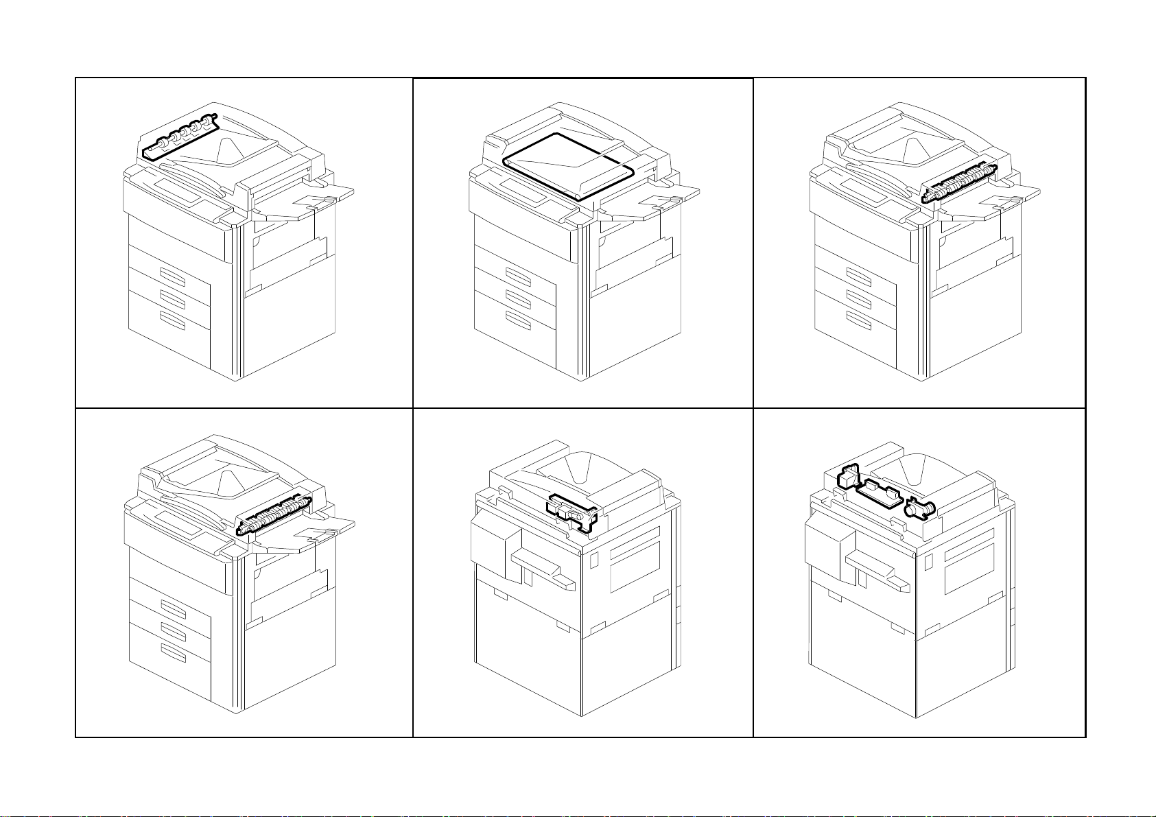
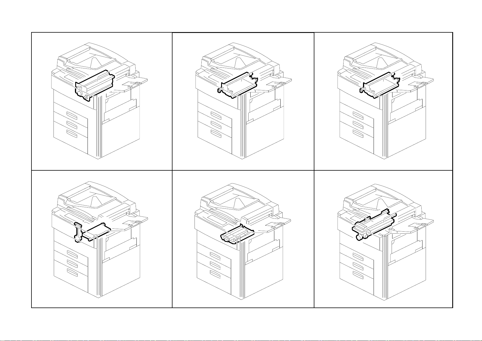
Location of Unit
1. Exterior 1 (A229)
See Page 15
4. DF Exterior (A229)
2. Exterior 2 (A229)
See Page 17
5. Original Feed 1 (A229)
3. Operation Panel (A229)
See Page 19
6. Original Feed 2 (A229)
See Page 21
A229 3 Parts Location and List
See Page 23
See Page 25
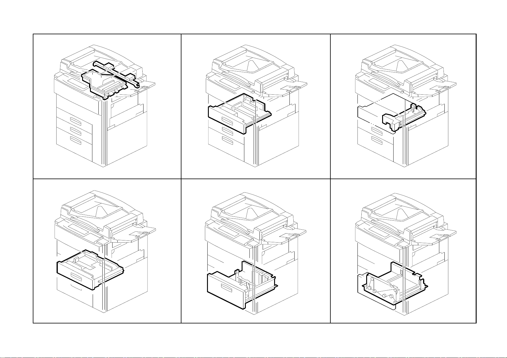
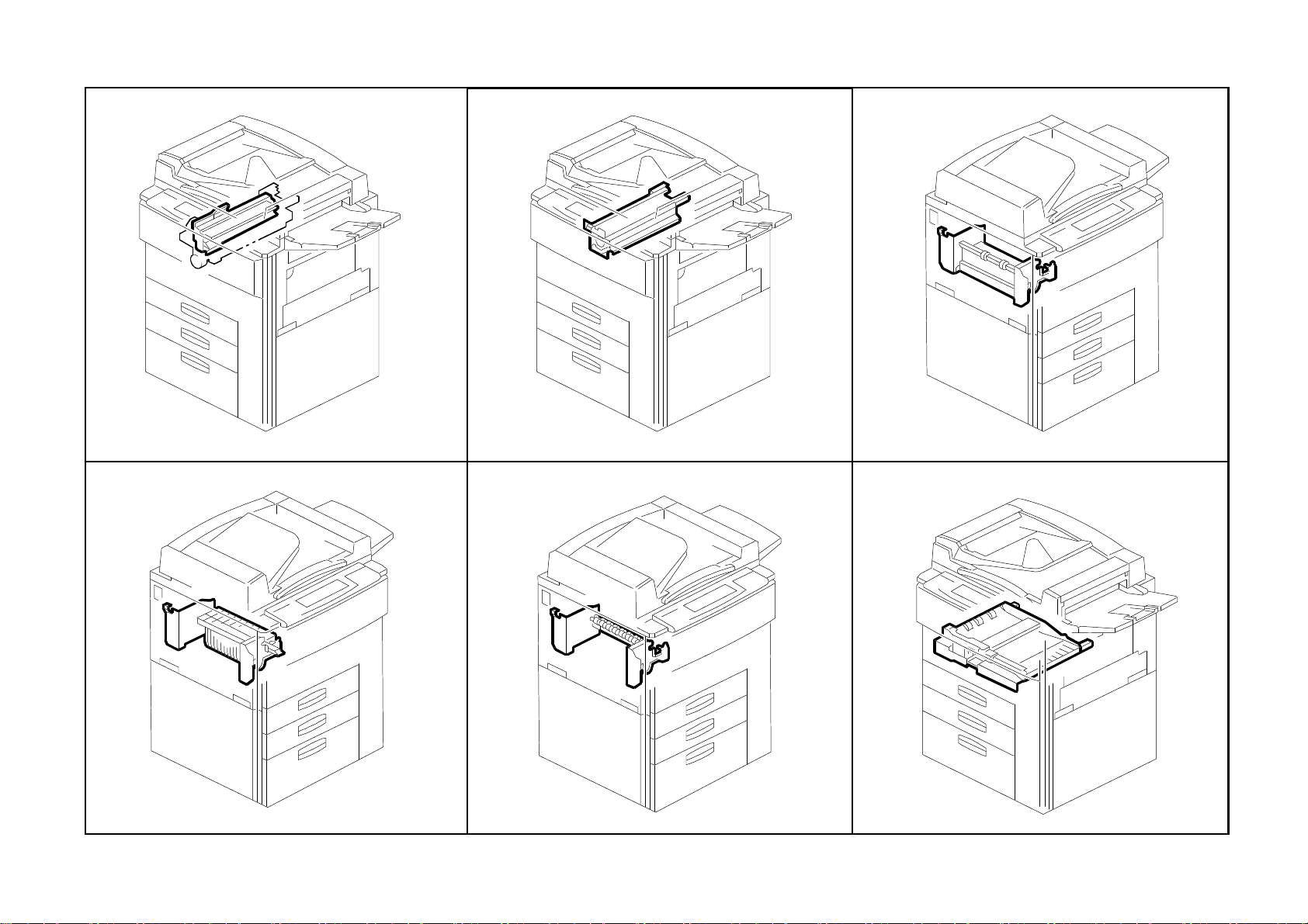
Location of Unit
7. Original Feed 3 (A229)
See Page 27
10. Original Exit 2 (A229)
8. Original Transport (A229)
See Page 29
11. DF Drive Section 1 (A229)
9. Original Exit 1 (A229)
See Page 31
12. DF Drive Section 2 (A229)
See Page 33
A229 4 Parts Location and List
See Page 35
See Page 37

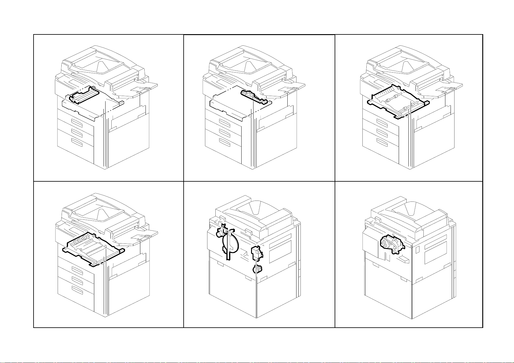
Location of Unit
13. DF Frame Section (A229)
See Page 39
16. Optics Section 3 (A229)
14. Optics Section 1 (A229)
See Page 41
17. Optics Section 4 (A229)
15. Optics Section 2 (A229)
See Page 43
18. Laser Unit (A229)
See Page 45
A229 5 Parts Location and List
See Page 47
See Page 49
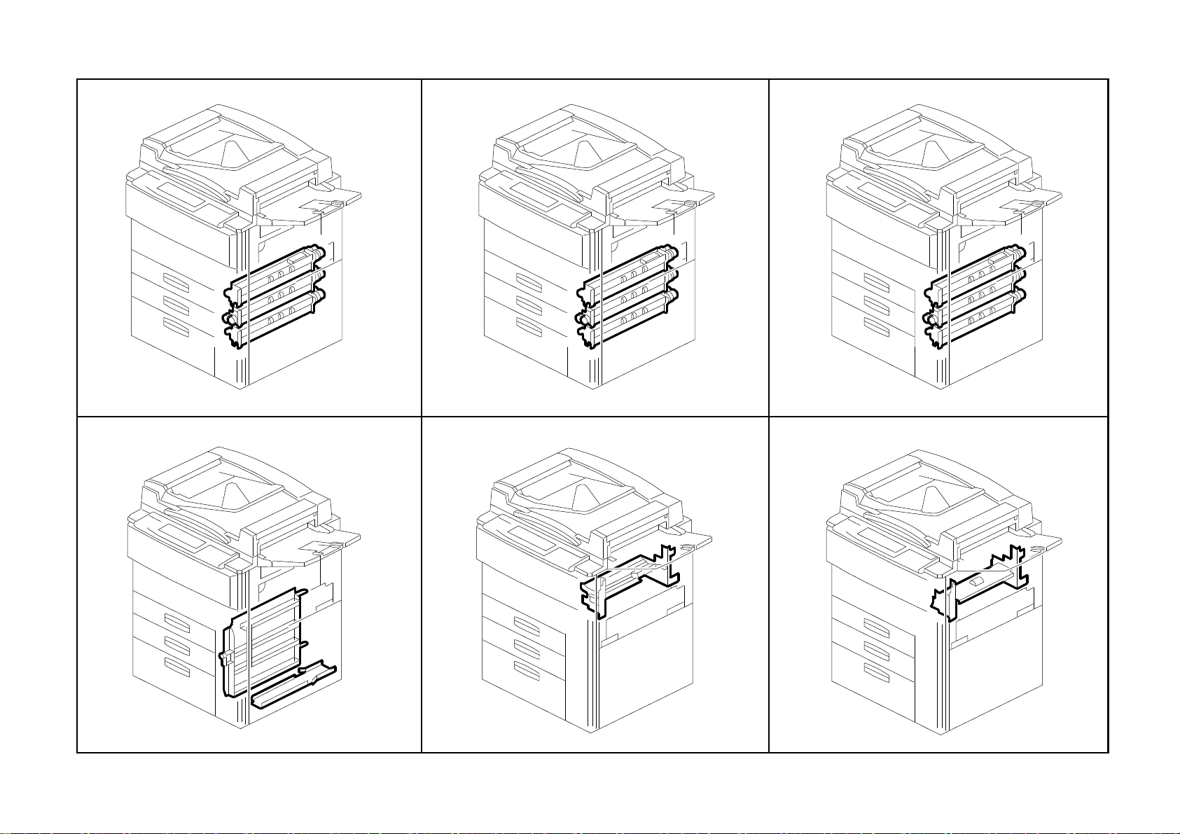
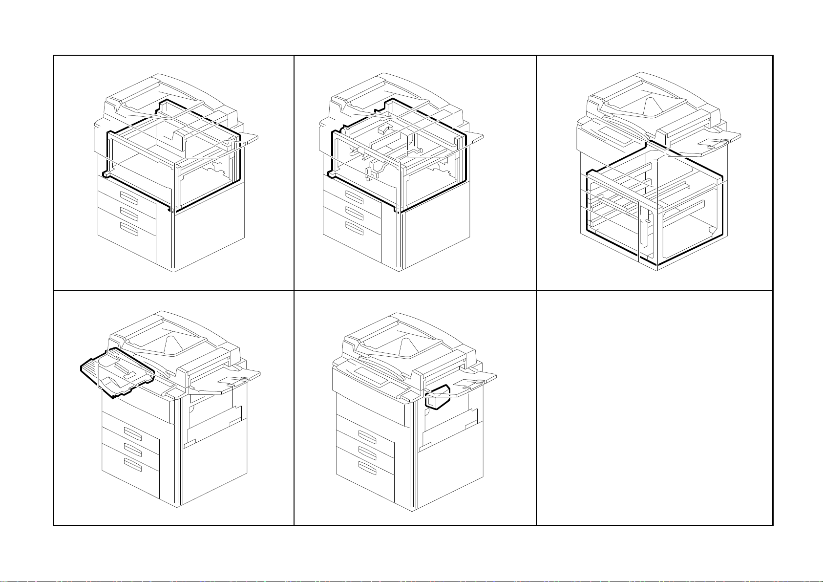
Location of Unit
19. By-pass Feed Unit (A229)
See Page 51
22. Universal Tray (A229)
20. Tandem Tray 1 (A229)
See Page 53
23. LCT Tray 1 (A229)
21. Tandem Tray 2 (A229)
See Page 55
24. LCT Tray 2 (A229)
See Page 57
A229 6 Parts Location and List
See Page 59
See Page 61
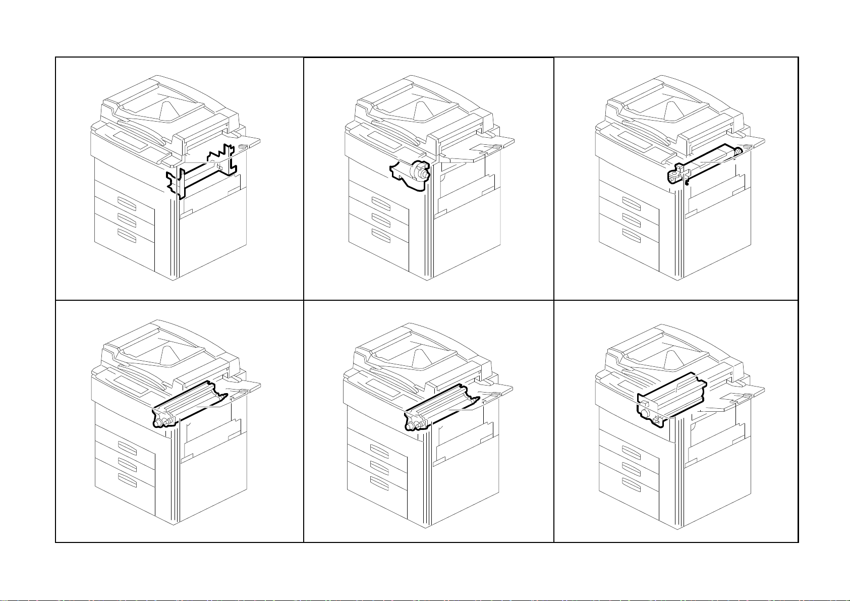
Location of Unit
25. Paper Feed Unit 1 (A229)
See Page 63
28. Vertical Transport (A229)
26. Paper Feed Unit 2 (A229)
See Page 65
29. Paper Registration 1 (A229)
27. Paper Feed Unit 3 (A229)
See Page 67
30. Paper Registration 2 (A229)
See Page 69
A229 7 Parts Location and List
See Page 71
See Page 73
Location of Unit
31. Paper Registration 3 (A229)
See Page 75
34. Development Unit 1 (A229)
32. Toner Bottle Holder (A229)
See Page 77
35. Development Unit 2 (A229)
33. Toner Hopper Section (A229)
See Page 79
36. PCU 1 (A229)
See Page 81
A229 8 Parts Location and List
See Page 83
See Page 85
Location of Unit
37. PCU 2 (A229)
See Page 87
40. Transfer Belt Unit 1 (A229)
38. PCU 3 (A229)
See Page 89
41. Transfer Belt Unit 2 (A229)
39. PCU 4 (A229)
See Page 91
42. Fusing Unit 1 (A229)
See Page 93
A229 9 Parts Location and List
See Page 95
See Page 97
Location of Unit
43. Fusing Unit 2 (A229)
See Page 99
46. Paper Exit Unit 2 (A229)
44. Fusing Unit 3 (A229)
See Page 101
47. Paper Exit Unit 3 (A229)
45. Paper Exit Unit 1 (A229)
See Page 103
48. Inverter/Duplex Unit 1 (A229)
See Page 105
A229 10 Parts Location and List
See Page 107
See Page 109
Location of Unit
49. Inverter/Duplex Unit 2 (A229)
See Page 111
52. Inverter/Duplex Unit 5 (A229)
50. Inverter/Duplex Unit 3 (A229)
See Page 113
53. Drive Section 1 (A229)
51. Inverter/Duplex Unit 4 (A229)
See Page 115
54. Drive Section 2 (A229)
See Page 117
A229 11 Parts Location and List
See Page 119
See Page 121

Location of Unit
55. Drive Section 3 (A229)
See Page 123
58. Electrical Section 1 (A229)
56. Drive Section 4 (A229)
See Page 125
59. Electrical Section 2 (A229)
57. Drive Section 5 (A229)
See Page 127
60. Electrical Section 3 (A229)
See Page 129
A229 12 Parts Location and List
See Page 131
See Page 133
Location of Unit
61. Frame Section 1 (A229)
See Page 135
64. Option Exit Tray (A814)
62. Frame Section 2 (A229)
See Page 137
65. Key Counter unit (A674)
63. Frame Section 3 (A229)
See Page 139
See Page 141
A229 13 Parts Location and List
See Page 143

1. Exterior 1 (A229)
Rev. 03/99
A229 14 Parts Location and List

1. Exterior 1 (A229)
Rev. 03/99
Index
No.
1 A229 1349 Decal - Toner Supply 1
2 A229 1350 Decal - Misfeed Removal 1
3 A229 1275 Guide Plate Lever 1
4 A229 1347 Fusing Unit Lever Feeler 1
5 A229 1342 Upper Hinge 1
6 AG07 0004 Magnetic Catch 1
7 A229 1257 Door Grip Ass’y 1
8 A229 1253 Front Door -A229 65cpm (RIC) 1
8 A229 1239 Front Door (NRG EU) 1
8 A229 1302 Front Door -A229 65cpm (SVN/GES NA) 1
8 A229 1283 Front Door -A229 55cpm (RIC) 1
9 A229 1355 Micro Switch Lever 1
10 A229 1259 Lower Hinge 1
11 A134 1383 Emblem (RIC) 1
11 A229 7016 Support Cover (INF) 1
12 A096 6184 Bank Inner Cover 1
13 AG05 0067 Knob - Transport Roller 1
14 AA00 0540 Decal - Misfeed Removal 1
15 A229 3298 Pawl Cover Sheet 1
16 A229 1320 Right Lower Inner Cover 1
17 A229 7010 Model Name Plate-GES 3265-A229 65cpm 1
17 A229 7011 Model Name Plate-NSA D465-A229 65cpm 1
17 A229 7012 Model Name Plate-REX 2865-A229 65cpm 1
17 A229 7013 Model Name Plate-SVN 9965DP-A229 65cpm 1
17 A229 7015 Model Name Plate-170X60 NRG-A229 65cpm 1
17 A229 7027 Model Name Plate-SVN 9955DP-A229 55cpm 1
17 A229 7014 Model Name Plate-GES 3255-A229 55cpm 1
18 A060 2512 Registration Roller Knob 2
19 A229 3290 Right Inner Cover 1
20 A229 1321 Safety Switch Inner Cover 1
Part No.
Description
Q’ty Per
Assembly
Index
No.
101 0450 4008B Tapping Screw - 4x8
102 0802 5124 Tapping Screw - M3x8
103 0434 0082W Tapping Screw - M4x8
104 0951 4006B Philips Screw With Washer - M4x6
105 0451 4008B Philips Tapping Screw - M4x8
106 0951 3006B Philips Screw With Flat Washer - M3x6
107 0450 3008B Tapping Screw - M3x8
Part No.
Description
Q’ty Per
Assembly
A229 15 Parts Location and List

2. Exterior 2 (A229)
A229 16 Parts Location and List

2. Exterior 2 (A229)
Index
No.
1 A229 1272 Left Upper Cover (230V) 1
1 A229 1271 Left Upper Cover (120V) 1
2 A229 1333 Connector Cap 1
3 A229 1361 Decal - Main Switch (230V) 1
3 A229 1360 Decal - Main Switch (120V) 1
4 A247 1299 Cap - 22 2
5 A229 1273 Rear Upper Cover 1
6 A229 1310 Upper Cover 1
7 AA14 3416 Stepped Screw - M4x3 2
8 A247 1318 Cap - 17 6
9 A229 1270 Lower Cover 2
10 AA15 2315 Tank Seal 1
11 AA03 2041 Toner Collection Bottle 1
12 A007 3751 Cap Large - Toner Collection Tank 1
13 AA00 0059 Caution Decal - English 1
14 A096 3711 Collection Tank Holder 1
15 A096 3712 Ratch 1
16 A229 1304 Large Capacity Tray Cover 1
17 A229 1332 Coupling Cap 1
18 A229 1260 Upper Right Cover 1
19 A229 1262 Optics Dust Filter 1
20 A229 1309 Rear Lower Cover 1
21 A229 1359 Shading Plate 1
22 A229 1327 Operation Panel Upper Cover 1
23 A229 1331 Key Counter Cap 1
24 A229 8521 Operating Instructions Holder - A5 1
25 A229 1311 Upper Right Cover 1
Part No.
Description
Q’ty Per
Assembly
Index
No.
101 0451 4008H Tapping Screw - 4x8
102 0450 3008B Tapping Screw - M3x8
Part No.
Description
Q’ty Per
Assembly
A229 17 Parts Location and List

3. Operation Panel (A229)
Rev. 07/99
A229 18 Parts Location and List
 Loading...