

Page 1

A229
PARTS CATALOG
RICOH GROUP COMPANIES
PN: RCPCA229
Page 2

PARTS CATALOG
A229
®
®
RICOH GROUP COMPANIES
Page 3

Page 4

A229
PARTS CATALOG
PN:RCPCA229
Page 5

Page 6

LEGEND
PRODUCT CODE COMPANY
GESTETNER RICOH SAVIN
A229 (65 CPM) 3265 Aficio 650 9965DP
A229 (55 CPM) 3255 Aficio 550 9955DP
A698 Large Capacity Tray (RT37)
A697 Finisher (SR730)
A808 Copier Connector Kit (TYPE A)
A852 Printer Controller Unit (TYPE 650)
G909/G912 Mailbox Unit / Bridge Unit (CS360 / Bridge Unit Type 460)
DOCUMENTATION HISTORY
REV. NO. DATE COMMENT
* 8/98 Original Printing
1 3/99 A808 Additi on
2 4/99 A852 Additi on
3 4/99 G909/G912 Addition
Page 7

Page 8

A229 PARTS CATALOG
TABLE OF CONTENTS
A229 PARTS LOCATION AND LIST
Location of Unit....................................................................... 2
1. Exterior 1 (A229)................................................................. 14
2. Exterior 2 (A229)................................................................. 16
3. Operation Panel (A229) ...................................................... 18
4. DF Exterior (A229).............................................................. 20
5. Original Feed 1 (A229)........................................................ 22
6. Original Feed 2 (A229)........................................................ 24
7. Original Feed 3 (A229)........................................................ 26
8. Original Transport (A229) ................................................... 28
9. Original Exit 1 (A229).......................................................... 30
10. Original Exit 2 (A229).......................................................... 32
11. DF Drive Section 1 (A229).................................................. 34
12. DF Drive Section 2 (A229).................................................. 36
13. DF Frame Section (A229)................................................... 38
14. Optics Section 1 (A229)...................................................... 40
15. Optics Section 2 (A229)...................................................... 42
16. Optics Section 3 (A229)...................................................... 44
17. Optics Section 4 (A229)...................................................... 46
18. Laser Unit (A229)....................... .. .. .... .. .. .... .. .. .... .. .. .... .. .. .... . 48
19. By-pass Feed Unit (A229)................................................... 50
20. Tandem Tray 1 (A229)....................................................... 52
21. Tandem Tray 2 (A229)........................................................ 54
22. Universal Tray (A229)......................................................... 56
23. LCT Tray 1 (A229) .............................................................. 58
24. LCT Tray 2 (A229) .............................................................. 60
25. Paper Feed Unit 1 (A229)................................................... 62
26. Paper Feed Unit 2 (A229)................................................... 64
27. Paper Feed Unit 3 (A229)................................................... 66
28. Vertical Transport (A229) ...... .............. .............. .............. .... 68
29. Paper Registration 1 (A229).............................. .............. .... 70
30. Paper Registration 2 (A229).............................. .............. .... 72
31. Paper Registration 3 (A229).............................. .............. .... 74
32. Toner Bottle Holder (A229)........................... .. .. .. ................. 76
33. Toner Hopper Section (A229)............................................. . 78
34. Development Unit 1 (A229)....................... .. .. .. .. .... .. .. .. .. .. .. .. 80
35. Development Unit 2 (A229)....................... .. .. .. .. .... .. .. .. .. .. .. .. 82
36. PCU 1 (A229)...................... ................................................ 84
37. PCU 2 (A229)...................... ................................................ 86
38. PCU 3 (A229)...................... ................................................ 88
39. PCU 4 (A229)...................... ................................................ 90
40. Transfer Belt Unit 1 (A229).................................................. 92
41. Transfer Belt Unit 2 (A229).................................................. 94
42. Fusing Unit 1 (A229)................................... .. .. .. .... .. .. .. .. .. .. .. . 96
43. Fusing Unit 2 (A229)................................... .. .. .. .... .. .. .. .. .. .. .. . 98
44. Fusing Unit 3 (A229)....................................... .. .... .. .. .. .... .. .. .100
45. Paper Exit Unit 1 (A229) .......................... .............. ..............102
46. Paper Exit Unit 2 (A229) .......................... .............. ..............104
47. Paper Exit Unit 3 (A229) .......................... .............. ..............106
48. Inverter/Duplex Unit 1 (A229)................ .............. .............. ..108
49. Inverter/Duplex Unit 2 (A229)................ .............. .............. ..110
50. Inverter/Duplex Unit 3 (A229)................ .............. .............. ..112
51. Inverter/Duplex Unit 4 (A229)................ .............. .............. ..114
52. Inverter/Duplex Unit 5 (A229)................ .............. .............. ..116
53. Drive Section 1 (A229) .......... .............. .............. .............. ....118
54. Drive Section 2 (A229) .......... .............. .............. .............. ....120
55. Drive Section 3 (A229) .......... .............. .............. .............. ....122
Page 9

Rev. 4/99
56. Drive Section 4 (A229)............................ .............. ..............124
57. Drive Section 5 (A229)............................ .............. ..............126
58. Electrical Section 1 (A229)...... .............. ............................ ..128
59. Electrical Section 2 (A229)...... .............. ............................ ..130
60. Electrical Section 3 (A229)...... .............. ............................ ..132
61. Frame Section 1 (A229)............................ .............. ............134
62. Frame Section 2 (A229)............................ .............. ............136
63. Frame Section 3 (A229)............................ .............. ............138
64. Option Exit Tray (A814)............... .. .... .. .. .. .. .. .. .. .. .. .. .. .. .. .... .. ..140
65. Key Counter unit (A674)...... .............. .............. .............. ......142
66. I/O Board (A229).................................................................144
67. SBICU Board (A229)....................... .... .. .. .. .. .. .... .. .. .. .. .... .. .. ..148
68. Decal And Document (A229) .... .............. .............. ..............156
69. Special Tools (A229)........................... .... .. .. .... .. .. .. .... .. .. .... ..160
A229 PARTS INDEX
Parts Index............................................................................... 2
LARGE CAPACITY TRAY A698 PARTS LOCATION AND LIST
1. Exterior (A698)..................................................................... 2
2. Tray Drive Section (A698).................................................... 4
3. Paper Feed Section 1 (A698)............................................... 6
4. Paper Feed Section 2 (A698)............................................... 8
5. Electrical Section (A698)...................................................... 10
6. Frame Section (A698).......................................................... 12
7. Decal And Document (A698) ............................................... 14
LARGE CAPACITY TRAY A698 PARTS INDEX
Parts Index............................................................................... 2
FINISHER A697 PARTS LOCATION AND LIST
LOCATION OF UNIT................................................................ 2
1. EXTERIOR (A697).......................... .................................... 6
2. STAPLE TRANSPORT 1 (A697) .................. .............. ........ 8
3. STAPLE TRANSPORT 2 (A697) .................. .............. ........ 10
4. STAPLE TRAY 1 (A697)........................ .......................... ... 12
5. STAPLE TRAY 2 (A697)........................ .......................... ... 14
6. STAPLER UNIT (A697) ...................................................... 16
7. TRANSPORT SECTION 1 (A697)............... .. .. .. .. ............... 18
8. TRANSPORT SECTION 2 (A697)............... .. .. .. .. ............... 20
9. PUNCH UNIT (A697).......................................................... 22
10. PAPER EXIT SECTION 1 (A697)....................................... 24
11. PAPER EXIT SECTION 2 (A697)....................................... 26
12. FRAME SECTION (A697) .................................................. 28
13. DRIVE SECTION (A697)..................... .. .. .. .. .. ..................... 30
14. ELECTRICAL SECTION (A697).... .............. .............. ......... 32
15. DECAL AND DOCUMENT (A697)......... .. .. .. ....................... 34
FINISHER A697 PARTS INDEX
PARTS INDEX.......................................................................... 2
PRINTER CONTROL UNIT A852 PARTS LOCATION AND LIST
1. PRINTER CONTROL (A852)....... ...................... .. .. .. ............. 2
2. PRINTER CONTROL BOARD (A852)..... .. ...................... ..... 4
3. ACCESSORIES (A852)................. .. .................... .. .. ............. 6
PRINTER CONTROL UNIT A852 PARTS INDEX
PARTS INDEX.......................................................................... 2
MAILBOX & BRIDGE UNIT G909/G912 PARTS LOCATION AND LIST
1. MAILBOX 1......................................................................... 2
2. MAILBOX 2......................................................................... 4
3. MAILBOX 3......................................................................... 6
4. MAILBOX 4......................................................................... 8
5. MAILBOX 5.........................................................................10
6. MAILBOX 6.........................................................................12
7. BRIDGE UNIT.....................................................................14
MAILBOX & BRIDGE UNIT G909/G912 PARTS INDEX
PARTS INDEX........................................................................ 2
Page 10

Page 11

A229
PARTS LOCATION AND LIST
Page 12

Page 13

This section instructs you as to the numbers and names of parts on this machine.
Page 14

Page 15

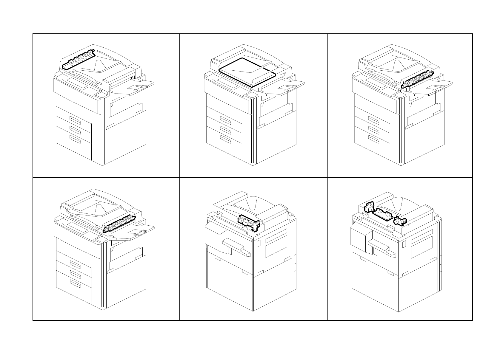
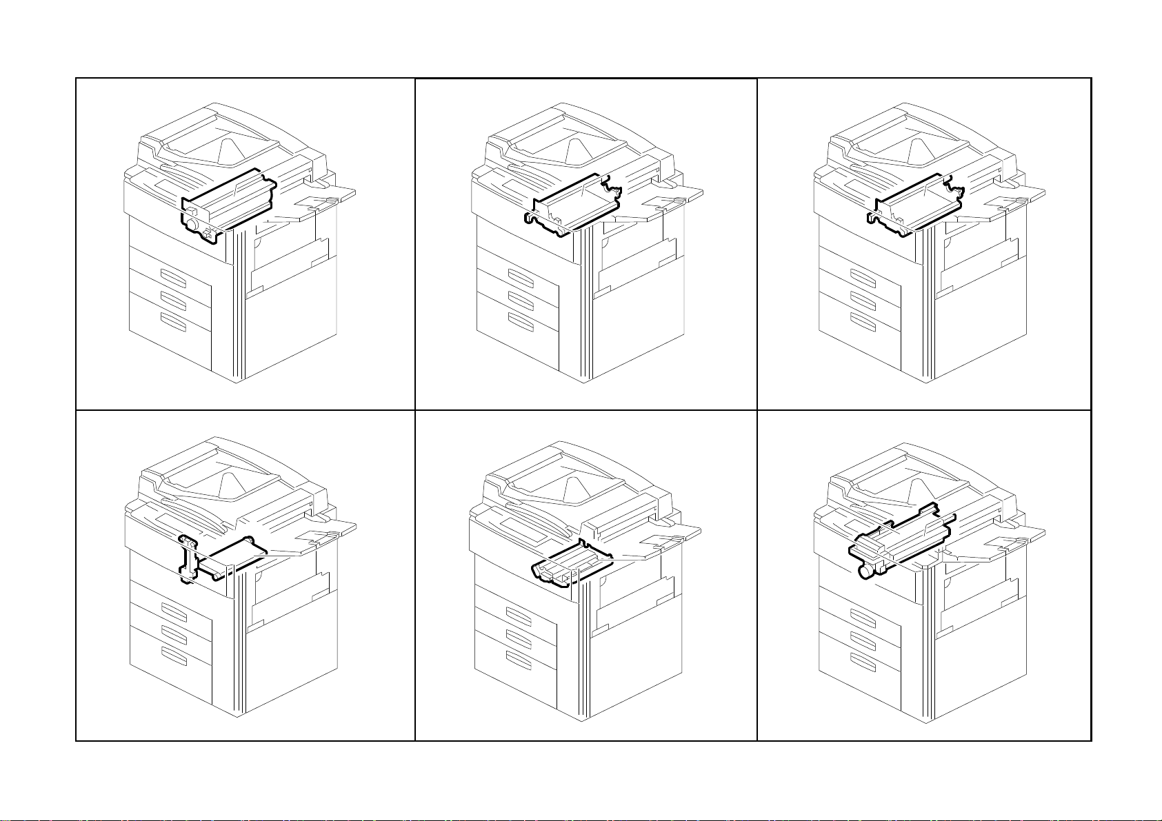
Location of Unit
1. Exterior 1 (A229)
See Page 15
4. DF Exterior (A229)
2. Exterior 2 (A229)
See Page 17
5. Original Feed 1 (A229)
3. Operation Panel (A229)
See Page 19
6. Original Feed 2 (A229)
See Page 21
A229 3 Parts Location and List
See Page 23
See Page 25
Page 16
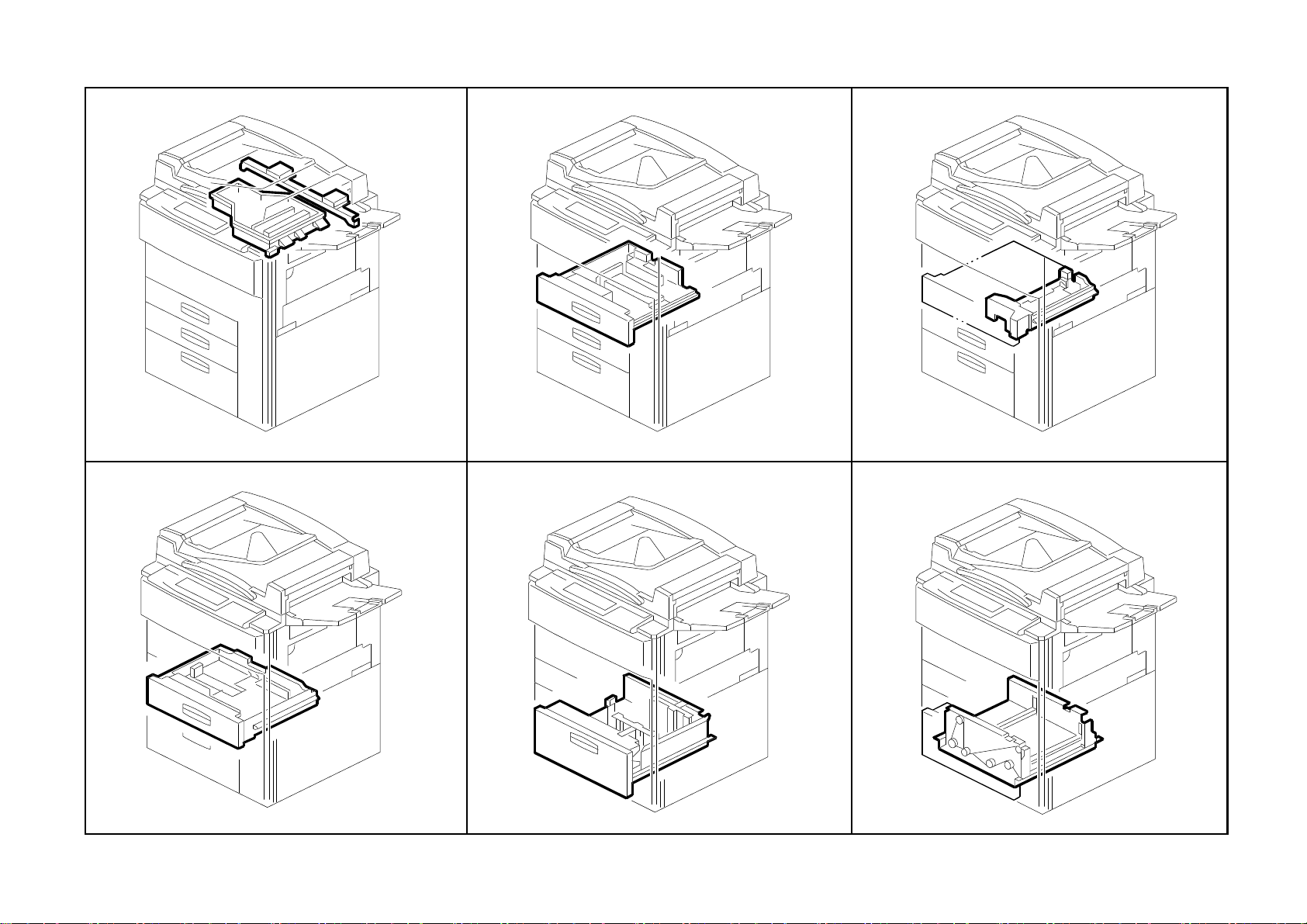
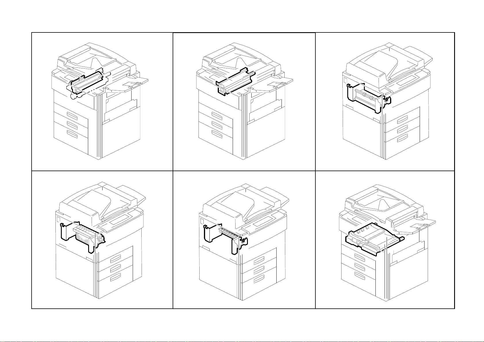
Location of Unit
7. Original Feed 3 (A229)
See Page 27
10. Original Exit 2 (A229)
8. Original Transport (A229)
See Page 29
11. DF Drive Section 1 (A229)
9. Original Exit 1 (A229)
See Page 31
12. DF Drive Section 2 (A229)
See Page 33
A229 4 Parts Location and List
See Page 35
See Page 37
Page 17

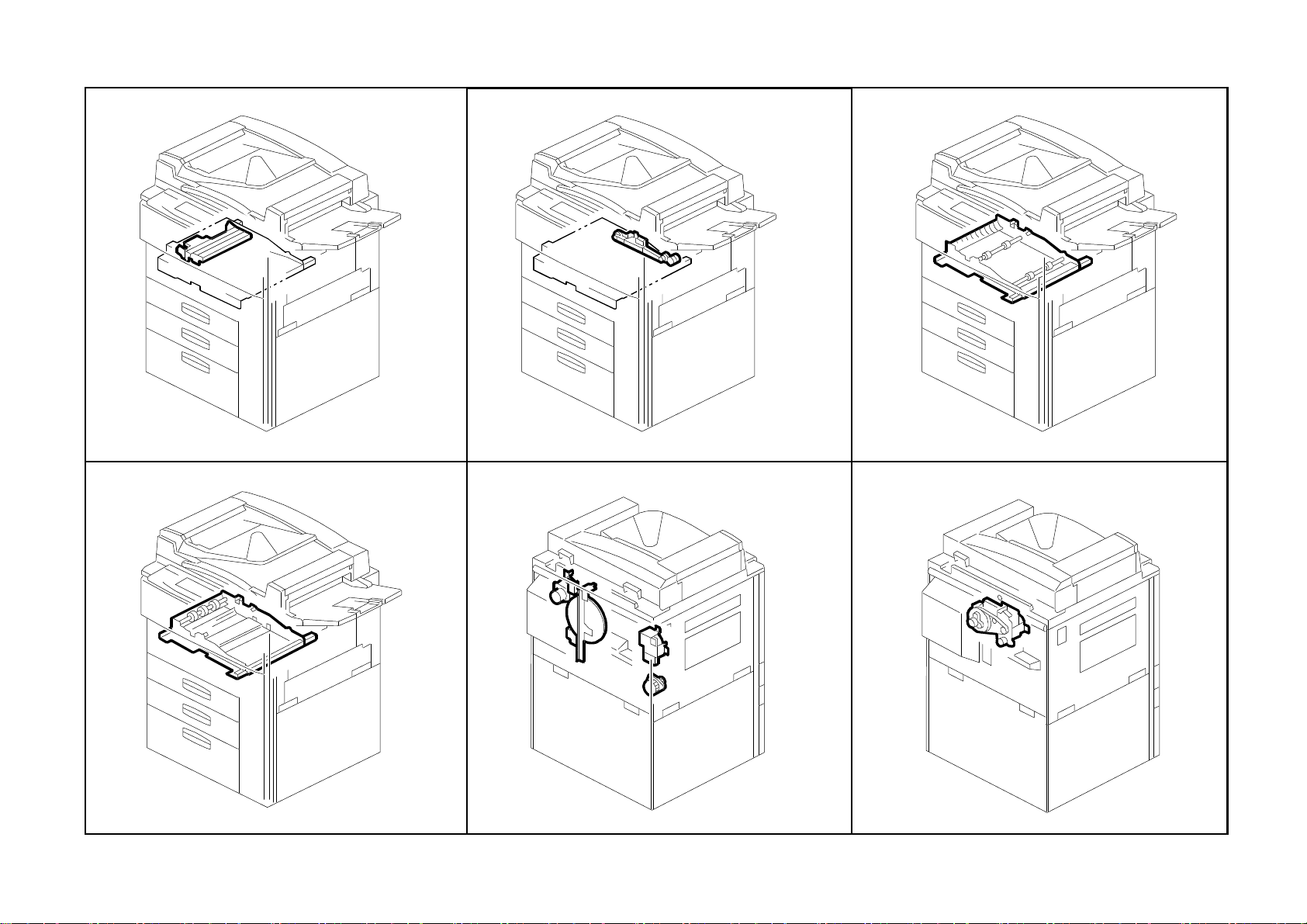
Location of Unit
13. DF Frame Section (A229)
See Page 39
16. Optics Section 3 (A229)
14. Optics Section 1 (A229)
See Page 41
17. Optics Section 4 (A229)
15. Optics Section 2 (A229)
See Page 43
18. Laser Unit (A229)
See Page 45
A229 5 Parts Location and List
See Page 47
See Page 49
Page 18
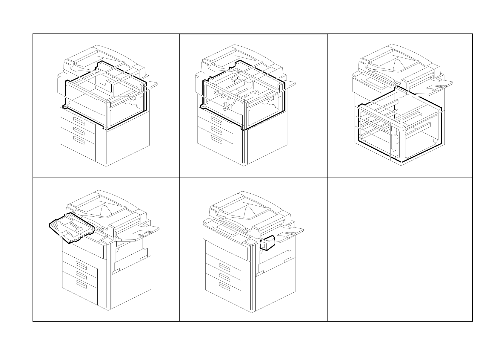
Location of Unit
19. By-pass Feed Unit (A229)
See Page 51
22. Universal Tray (A229)
20. Tandem Tray 1 (A229)
See Page 53
23. LCT Tray 1 (A229)
21. Tandem Tray 2 (A229)
See Page 55
24. LCT Tray 2 (A229)
See Page 57
A229 6 Parts Location and List
See Page 59
See Page 61
Page 19
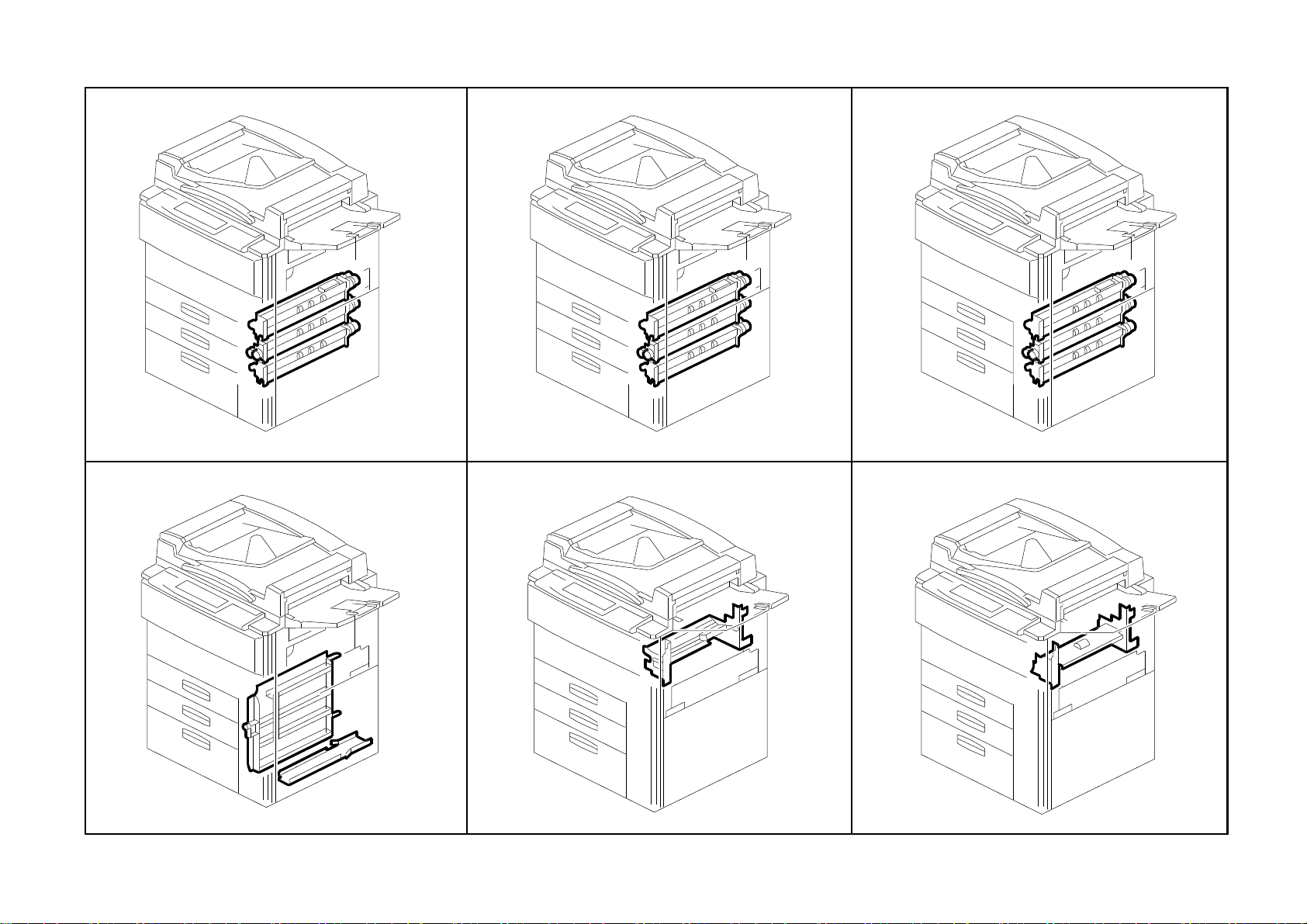
Location of Unit
25. Paper Feed Unit 1 (A229)
See Page 63
28. Vertical Transport (A229)
26. Paper Feed Unit 2 (A229)
See Page 65
29. Paper Registration 1 (A229)
27. Paper Feed Unit 3 (A229)
See Page 67
30. Paper Registration 2 (A229)
See Page 69
A229 7 Parts Location and List
See Page 71
See Page 73
Page 20
Location of Unit
31. Paper Registration 3 (A229)
See Page 75
34. Development Unit 1 (A229)
32. Toner Bottle Holder (A229)
See Page 77
35. Development Unit 2 (A229)
33. Toner Hopper Section (A229)
See Page 79
36. PCU 1 (A229)
See Page 81
A229 8 Parts Location and List
See Page 83
See Page 85
Page 21
Location of Unit
37. PCU 2 (A229)
See Page 87
40. Transfer Belt Unit 1 (A229)
38. PCU 3 (A229)
See Page 89
41. Transfer Belt Unit 2 (A229)
39. PCU 4 (A229)
See Page 91
42. Fusing Unit 1 (A229)
See Page 93
A229 9 Parts Location and List
See Page 95
See Page 97
Page 22
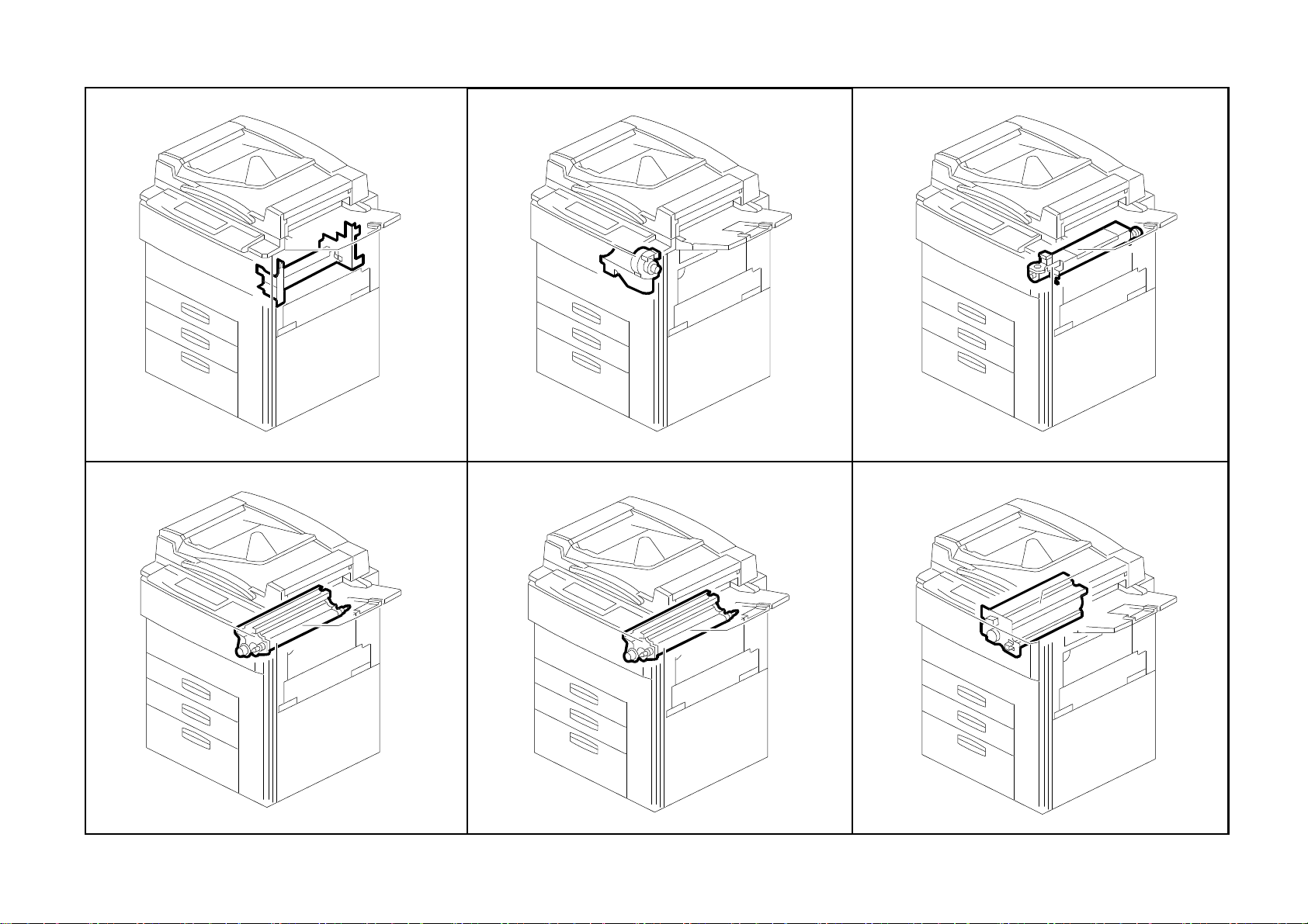
Location of Unit
43. Fusing Unit 2 (A229)
See Page 99
46. Paper Exit Unit 2 (A229)
44. Fusing Unit 3 (A229)
See Page 101
47. Paper Exit Unit 3 (A229)
45. Paper Exit Unit 1 (A229)
See Page 103
48. Inverter/Duplex Unit 1 (A229)
See Page 105
A229 10 Parts Location and List
See Page 107
See Page 109
Page 23
Location of Unit
49. Inverter/Duplex Unit 2 (A229)
See Page 111
52. Inverter/Duplex Unit 5 (A229)
50. Inverter/Duplex Unit 3 (A229)
See Page 113
53. Drive Section 1 (A229)
51. Inverter/Duplex Unit 4 (A229)
See Page 115
54. Drive Section 2 (A229)
See Page 117
A229 11 Parts Location and List
See Page 119
See Page 121
Page 24

Location of Unit
55. Drive Section 3 (A229)
See Page 123
58. Electrical Section 1 (A229)
56. Drive Section 4 (A229)
See Page 125
59. Electrical Section 2 (A229)
57. Drive Section 5 (A229)
See Page 127
60. Electrical Section 3 (A229)
See Page 129
A229 12 Parts Location and List
See Page 131
See Page 133
Page 25
Location of Unit
61. Frame Section 1 (A229)
See Page 135
64. Option Exit Tray (A814)
62. Frame Section 2 (A229)
See Page 137
65. Key Counter unit (A674)
63. Frame Section 3 (A229)
See Page 139
See Page 141
A229 13 Parts Location and List
See Page 143
Page 26

1. Exterior 1 (A229)
Rev. 03/99
A229 14 Parts Location and List
Page 27

1. Exterior 1 (A229)
Rev. 03/99
Index
No.
1 A229 1349 Decal - Toner Supply 1
2 A229 1350 Decal - Misfeed Removal 1
3 A229 1275 Guide Plate Lever 1
4 A229 1347 Fusing Unit Lever Feeler 1
5 A229 1342 Upper Hinge 1
6 AG07 0004 Magnetic Catch 1
7 A229 1257 Door Grip Ass’y 1
8 A229 1253 Front Door -A229 65cpm (RIC) 1
8 A229 1239 Front Door (NRG EU) 1
8 A229 1302 Front Door -A229 65cpm (SVN/GES NA) 1
8 A229 1283 Front Door -A229 55cpm (RIC) 1
9 A229 1355 Micro Switch Lever 1
10 A229 1259 Lower Hinge 1
11 A134 1383 Emblem (RIC) 1
11 A229 7016 Support Cover (INF) 1
12 A096 6184 Bank Inner Cover 1
13 AG05 0067 Knob - Transport Roller 1
14 AA00 0540 Decal - Misfeed Removal 1
15 A229 3298 Pawl Cover Sheet 1
16 A229 1320 Right Lower Inner Cover 1
17 A229 7010 Model Name Plate-GES 3265-A229 65cpm 1
17 A229 7011 Model Name Plate-NSA D465-A229 65cpm 1
17 A229 7012 Model Name Plate-REX 2865-A229 65cpm 1
17 A229 7013 Model Name Plate-SVN 9965DP-A229 65cpm 1
17 A229 7015 Model Name Plate-170X60 NRG-A229 65cpm 1
17 A229 7027 Model Name Plate-SVN 9955DP-A229 55cpm 1
17 A229 7014 Model Name Plate-GES 3255-A229 55cpm 1
18 A060 2512 Registration Roller Knob 2
19 A229 3290 Right Inner Cover 1
20 A229 1321 Safety Switch Inner Cover 1
Part No.
Description
Q’ty Per
Assembly
Index
No.
101 0450 4008B Tapping Screw - 4x8
102 0802 5124 Tapping Screw - M3x8
103 0434 0082W Tapping Screw - M4x8
104 0951 4006B Philips Screw With Washer - M4x6
105 0451 4008B Philips Tapping Screw - M4x8
106 0951 3006B Philips Screw With Flat Washer - M3x6
107 0450 3008B Tapping Screw - M3x8
Part No.
Description
Q’ty Per
Assembly
A229 15 Parts Location and List
Page 28

2. Exterior 2 (A229)
A229 16 Parts Location and List
Page 29

2. Exterior 2 (A229)
Index
No.
1 A229 1272 Left Upper Cover (230V) 1
1 A229 1271 Left Upper Cover (120V) 1
2 A229 1333 Connector Cap 1
3 A229 1361 Decal - Main Switch (230V) 1
3 A229 1360 Decal - Main Switch (120V) 1
4 A247 1299 Cap - 22 2
5 A229 1273 Rear Upper Cover 1
6 A229 1310 Upper Cover 1
7 AA14 3416 Stepped Screw - M4x3 2
8 A247 1318 Cap - 17 6
9 A229 1270 Lower Cover 2
10 AA15 2315 Tank Seal 1
11 AA03 2041 Toner Collection Bottle 1
12 A007 3751 Cap Large - Toner Collection Tank 1
13 AA00 0059 Caution Decal - English 1
14 A096 3711 Collection Tank Holder 1
15 A096 3712 Ratch 1
16 A229 1304 Large Capacity Tray Cover 1
17 A229 1332 Coupling Cap 1
18 A229 1260 Upper Right Cover 1
19 A229 1262 Optics Dust Filter 1
20 A229 1309 Rear Lower Cover 1
21 A229 1359 Shading Plate 1
22 A229 1327 Operation Panel Upper Cover 1
23 A229 1331 Key Counter Cap 1
24 A229 8521 Operating Instructions Holder - A5 1
25 A229 1311 Upper Right Cover 1
Part No.
Description
Q’ty Per
Assembly
Index
No.
101 0451 4008H Tapping Screw - 4x8
102 0450 3008B Tapping Screw - M3x8
Part No.
Description
Q’ty Per
Assembly
A229 17 Parts Location and List
Page 30

3. Operation Panel (A229)
Rev. 07/99
A229 18 Parts Location and List
Page 31

3. Operation Panel (A229)
Rev. 07/99
Index
No.
1 A229 1412 Operation Panel Ass’y (LT) 1
1 A229 1414 Operation Panel Ass’y (A4) 1
2 A229 1442 Operation Panel Case (A4) 1
2 A229 1441 Operation Panel Case (LT) 1
3 A229 1466 Guidance Sheet 1
4 A229 1461 Application Cap 1
5 A229 1465 LED Guide 1
6 A229 1459 Keytop - Power Source 1
7 A229 1457 Keytop - Check 1
8 A229 1456 Keytop - Interrupt 1
9 A229 1475 Keytop - Standby 1
10 A229 1455 Keytop - Program 1
11 A229 1451 Keytop - 10key 1
12 A229 1453 Keytop - Clear/Stop 1
13 A229 1452 Keytop - Start 1
14 AW01 0079 Optics Sensor 1
15 A229 1462 10key Board 1
16 A229 1468 10key Sheet 1
17 A229 1433 LCDC Cover 1
18 A229 5200 LCDC Board 1
19 A229 1432 LCDC Bracket 1
20 A229 5215 HVGA LCD 1
21 A229 1425 Touch Panel Ass’y 1
22 A229 1463 Application Board 1
23 A229 1467 Application Sheet 1
24 A229 1458 Keytop - Tool 1
25 A229 1460 Dial - Contrast 1
26 A153 6409 Decal - Keytop Cover (GES/NRG) 1
26 C225 2866 Decal - Keytop Cover (REX) 1
26 C225 2867 Decal - Keytop Cover (NASHUA) 1
27 A229 1472 Support Plate - Operation Panel 1
Part No.
Description
Q’ty Per
Assembly
Index
No.
101 0451 3006B Tapping Screw - M3x6
Part No.
Description
Q’ty Per
Assembly
A229 19 Parts Location and List
Page 32

4. DF Exterior (A229)
A229 20 Parts Location and List
Page 33

4. DF Exterior (A229)
Index
No.
1 A806 1821 Original Table 1
2 A610 6051 Decal - Document Set 1
3 A376 4911 Stepped Screw - Left Hinge 2
4 A806 1711 Front Cover 1
5 A806 1791 Original Table Cover 1
6 A806 1731 Rear Cover 1
7 A806 4341 Display Panel 1
8 5446 2824 Screw - Duplex Guide Plate 1
9 A548 1241 Driven Roller Ass’y 4
10 AA12 0032 Anti static Brush 1
11 A806 3266 Discharge Brush Bracket 1
12 A806 3261 Inner Back Cover Bracket 1
13 A806 3251 Exit Cover Bracket 1
14 A806 1781 Exit Cover 1
15 G012 1531 Magnet 2
16 A229 1393 Exit Tray Holder 1
17 A229 1395 Mylar - Large 2
18 A229 1394 Exit Tray 1
19 A666 2421 Sub - Shift Tray 1
20 A229 1396 Mylar - Small 1
Part No.
Description
Q’ty Per
Assembly
Index
No.
101 0451 3008B Tapping Screw - M3x8
102 0951 5010B Philips Screw With Washer - M5x10
103 0450 4012B Tapping Screw - M4x12
104 0451 4008H Tapping Screw - 4x8
Part No.
Description
Q’ty Per
Assembly
A229 21 Parts Location and List
Page 34

5. Original Feed 1 (A229)
A229 22 Parts Location and List
Page 35

5. Original Feed 1 (A229)
Index
No.
1 A806 1751 Feed Cover 1
2 A806 4311 Decal - Misfeed Removal 1
3 A806 1371 Magnet Catch - Paper Feed Cover 2
4 A806 4331 Decal - Original Size 1
5 A806 1361 Cover Bracket 1
6 A806 1181 Pressure Roller Bracket - Pull Out 2
7 A806 4222 Compression Spring 2
8 A680 1661 Bushing - 4mm 4
9 A806 1196 Driven Roller 1
10 A806 5710 Pull Out Sensor Harness 1
11 5446 2824 Screw - Duplex Guide Plate 1
12 A806 4211 Compression Spring 2
13 A806 1191 Pull Out Driven Roller 1
14 A806 1335 Original Table Guide Plate 1
15 AW01 0076 Photo sensor - PS-117D1 1
16 A806 1171 Turn Guide Plate 1
17 A806 1881 Side Fence 1
18 A376 4599 Side Fence Pad 1
19 A806 1351 Original Sensor Feeler 1
20 A806 1353 Feeler Stud 1
21 A680 4151 Side Fence Guide 1
22 5206 2686 Snap Ring 1
23 A806 1861 Original Table Base 1
24 5215 2621 Snap Ring - M6 1
25 A806 4321 Decal - Original Stack Height 1
26 A806 5730 Original Sensor Harness 1
27 AW02 0075 Photo interrupter 2
28 A806 1356 Original Sensor Bracket 1
29 A806 2281 Gear - Z47 1
30 5053 0447 Bushing - 6mm 1
31 A806 1346 Base Shaft 1
32 A806 1342 Base Lever 1
33 5053 0223 Bushing - 8mm 1
34 A806 1331 Original Table Stay 1
35 A806 5785 Grounding Harness 1
Part No.
Description
Q’ty Per
Assembly
Index
No.
36 A806 5780 Grounding Harness 1
101 0450 4008B Tapping Screw - 4x8
102 0451 3008B Tapping Screw - M3x8
103 0720 0030B Retaining Ring - M3
104 0450 3008B Tapping Screw - M3x8
105 1105 0199 Clamp
106 1105 0328 Harness Clamp - ES-0505
107 0632 0140G Parallel Pin
108 0720 0040B Retaining Ring - M4
109 0720 0060B Retaining Ring - M6
Part No.
Description
Q’ty Per
Assembly
A229 23 Parts Location and List
Page 36

6. Original Feed 2 (A229)
A229 24 Parts Location and List
Page 37

6. Original Feed 2 (A229)
Rev. 03/28/2000
Index
No.
1 A806 1152 Upper Guide Plate 1
2 A806 1151 Upper Guide Plate 1
3 A806 1286 Bushing 1
4 A806 1161 Entrance Guide Plate - Front 1
5 A806 1163 Guide Plate Cushion 4
6 A680 1621 Feed-in Unit Stopper 1
7 A628 1225 Bushing - 8mm 4
8 A806 1293 Feed Belt Drive Roller 1
9 A806 1292 Feed Belt Bracket 1
10 A806 61295 Feed Belt 1
11 A806 1294 Feed Belt Driven Roller 1
12 A806 1298 Transport Belt Roller Shaft 1
13 A806 64261 Spring - Belt Guide Roller 2
14 A806 1282 Separation Drive Shaft 1
15 A806 1162 Entrance Guide Plate - Inner 1
16 A806 1327 Release Lever 1
17 A806 1312 Pickup Roller Bracket 1
18 A806 2271 Gear - Z18 1
19 A806 2151 Timing Pulley - T19/Z23 S2M/M0.6 1
20 5447 2681 Snap Ring 3
21 5053 0447 Bushing - 6mm 2
22 A806 4118 Timing Belt - B40S2M148 1
23 A806 1321 Pickup Roller 1
24 AA13 2171 Spacer - 6x20x1 1
25 A806 2153 Timing Pulley - T27 S2M 1
26 A680 1671 Separation Roller 1
27 A293 6399 Torque Limiter - 53mm 1
28 A806 1141 Reverse Roller Stay 1
29 A806 5725 Sensor Harness 1
30 5415 4145 Stud 1
31 AA06 3315 Spring - Belt Drive Shaft 1
32 A806 2512 Reverse Roller Shaft 1
33 A418 1158 Spacer - M6.5x1 2
Part No.
Description
Q’ty Per
Assembly
Index
No.
101 0451 3008B Tapping Screw - M3x8
102 0720 0040B Retaining Ring - M4
103 0720 0060B Retaining Ring - M6
104 1105 0199 Clamp
105 1105 0231 Clamp
106 0741 3506 Ball Bearing - 6x12x4 mm
107 0622 0120E Spring Pin - 2x12mm
108 0741 3706 Ball Bearing - 6x10x3
Part No.
Description
Q’ty Per
Assembly
A229 25 Parts Location and List
Page 38

7. Original Feed 3 (A229)
A229 26 Parts Location and List
Page 39

7. Original Feed 3 (A229)
Index
No.
1 AA14 3074 Stepped Screw - M4x5 1
2 A806 1271 Pull Out Drive Roller 1
3 A806 1276 Transport Drive Roller 1
4 A806 5745 Paper Size Sensor Harness 1
5 AW02 0104 Photointerruptor 1
6 AW02 0095 Photointerrupter 2
7 A806 1226 Paper Size Sensor Bracket 1
8 A806 1211 Middle Guide Plate 1
9 A806 1241 Lower Guide Plate 1
10 A806 1251 Transport Roller Arm 4
11 A806 4222 Compression Spring 2
12 A806 1266 Driven Roller 2
13 5324 1658 Bushing- 4x8x4.5mm 2
14 A806 4221 Compression Spring 2
15 A806 1261 Middle Driven Roller 1
16 A806 1256 Middle Shaft - Roller Arm 1
17 A806 1257 Roller Arm Shaft 2
18 A806 1231 Paper Feed Base 1
19 A376 3242 Anti static Brush 1
20 A422 1063 Seal - 0.7x13x20 1
21 AW02 0075 Photo interrupter 1
22 A806 1221 Registration Sensor Bracket 1
23 AW01 0076 Photo sensor - PS-117D1 1
24 A806 5740 Registration Sensor Harness 1
25 A806 5735 Pick Up Sensor Harness 1
Part No.
Description
Q’ty Per
Assembly
Index
No.
101 0741 3506 Ball Bearing - 6x12x4 mm
102 0720 0040B Retaining Ring - M4
103 0451 3008B Tapping Screw - M3x8
104 1105 0328 Harness Clamp - ES-0505
105 0451 3006B Tapping Screw - M3x6
106 1105 0199 Clamp
107 0720 0030B Retaining Ring - M3
108 0450 3008B Tapping Screw - M3x8
109 1106 0193 Bushing - 7.9mm
110 0451 3012B Tapping Screw With Washer - M3x12
111 0741 3808 Ball Bearing - 8x16x5mm
Part No.
Description
Q’ty Per
Assembly
A229 27 Parts Location and List
Page 40

8. Original Transport (A229)
A229 28 Parts Location and List
Page 41

8. Original Transport (A229)
Index
No.
1 A663 1412 Transport Base Plate 1
2 5419 5714 Stepped Screw - M4 8
3 A232 3563 Ball Bearing - 6x12x4 3
4 A680 1481 Transport Belt 1
5 A680 1431 Belt Drive Roller 1
6 A680 1451 Belt Pressure Roller 1
7 A548 1461 Belt Pressure Roller 3
8 A548 1442 Transport Arm 1
9 A610 2161 Belt Pressure Roller - 24 1
10 A663 1422 Transport Stay 1
11 A376 2132 Belt Driven Roller 1
12 A680 1446 Transport Unit Arm 1
13 A680 1443 Arm Shaft 1
14 A806 4114 Timing Belt - B40S3M174 1
15 A548 2139 Pulley 1
16 5053 0447 Bushing - 6mm 2
Part No.
Description
Q’ty Per
Assembly
Index
No.
101 0720 0040E Retaining Ring - M4
102 0805 0089 Retaining Ring - M4
103 0720 0030E Retaining Ring - M3
104 0451 3006B Tapping Screw - M3x6
105 0720 0040B Retaining Ring - M4
Part No.
Description
Q’ty Per
Assembly
A229 29 Parts Location and List
Page 42

9. Original Exit 1 (A229)
A229 30 Parts Location and List
Page 43

9. Original Exit 1 (A229)
Index
No.
1 A806 3162 Reverse Exit Guide 1
2 AW01 0076 Photosensor - PS-117D1 2
3 A806 3161 Left Guide Plate 1
4 A806 3151 Driven Exit Roller 4
5 A806 3142 Guide Plate Bracket 1
6 A806 4233 Tension Spring 4
7 A806 3171 Lower Exit Cover 1
8 A806 3291 Original Stopper Cushion 4
9 A548 1233 Driven Roller 4
10 A548 1234 Driven Roller Arm 4
11 A806 3131 Lower Exit Guide Plate 1
12 5053 0447 Bushing - 6mm 2
13 A806 3281 Timing Pulley - T14 S3M 1
14 A806 4122 Timing Belt - B40S3M150 1
15 A806 3211 Right Exit Guide Plate 1
16 AA12 0032 Antistatic Brush 1
17 A806 3222 Seal 1
18 A806 3221 Exit Ground Plate 1
19 AW02 0075 Photointerrupter 1
20 A806 1921 Right Cover 1
21 A806 3111 Drive Exit Roller 1
Part No.
Description
Q’ty Per
Assembly
Index
No.
101 0720 0040B Retaining Ring - M4
102 0451 3008B Tapping Screw - M3x8
103 0450 3008B Tapping Screw - M3x8
Part No.
Description
Q’ty Per
Assembly
A229 31 Parts Location and List
Page 44

10. Original Exit 2 (A229)
A229 32 Parts Location and List
Page 45

10. Original Exit 2 (A229)
Index
No.
1 A680 2321 Pulley - 30T 2
2 5053 0447 Bushing - 6mm 5
3 A548 1217 Antistatic Brush - Paper Exit 1
4 AA06 0588 Pressure Spring 4
5 A548 1233 Driven Roller 4
6 A548 1234 Driven Roller Arm 4
7 A806 3181 Reverse Guide Plate 1
8 A548 1261 Exit Roller 1
9 A548 1320 Invertor Gate Plate 1
10 A548 1317 Lever Cushion 2
11 A806 4232 Tension Spring 1
12 A806 3271 Reverse Drive Roller 1
13 A548 1231 Guide Roller 1
14 5215 2621 Snap Ring - M6 1
15 A806 3191 Exit Junction Gate 1
16 A806 4231 Tension Spring 1
17 A806 4121 Timing Belt - B40S3M213 1
18 A548 2137 Timing Pulley - 18Z 1
19 A469 3113 Rubber Seal - 1x6x10mm 2
20 A806 3311 Invertor Solenoid 1
21 A680 1384 Solenoid - Lower Invertor Gate 1
22 A806 3312 Solenoid Bracket 1
Part No.
Description
Q’ty Per
Assembly
Index
No.
101 0720 0040B Retaining Ring - M4
102 0632 0120G Parallel Pin - 2x12
103 0805 0089 Retaining Ring - M4
104 0451 3008B Tapping Screw - M3x8
105 1105 0328 Harness Clamp - ES-0505
106 0353 0030B Philips Truss Head Screw - M3x3
Part No.
Description
Q’ty Per
Assembly
A229 33 Parts Location and List
Page 46

11. DF Drive Section 1 (A229)
A229 34 Parts Location and List
Page 47

11. DF Drive Section 1 (A229)
Index
No.
1 A806 4116 Timing Belt - B40S3M177 1
2 A806 2141 Timing Pulley - T22 S3M 1
3 5053 0447 Bushing - 6mm 2
4 A806 2122 Timing Pulley - T24 1
5 A806 4113 Timing Belt - B40S3M276 1
6 A806 2113 Timing Pulley - T23 S3M 1
7 5937 4158 Spring Washer - BD10 2
8 A806 2322 Paper Feed Stay 1
9 A806 4234 Tension Spring 1
10 AB03 0354 Pulley - 20T 1
11 A806 2921 Stepper Motor Ass’y - DC30.4W 1
12 A680 2611 Stepper Motor - DC 6.7W 1
13 A806 5720 Paper Feed Motor Harness 1
14 A806 2311 Motor Bracket 1
15 A806 2711 Display Bracket 1
16 5936 5231 Indicator Board 1
17 A806 4112 Timing Belt - B40S2M408 1
18 A806 4111 Timing Belt - B60S2M200 1
19 A680 2231 Pulley - 44T/20T 1
20 A806 2111 Timing Pulley - T28 S2M 1
21 5936 2321 Rubber Bushing - Vibration Damper 3
22 A806 2232 Gear - 18Z 1
23 A806 2611 Gear Stopper 1
24 A806 2233 Gear Shaft - 18Z 1
25 A806 2213 Gear - 22Z 1
26 A806 2331 Paper Feed Bracket 1
27 A680 2262 Feeler - Pick-up Roller Cam 1
28 A806 2211 Gear - 22Z 1
29 A806 2422 Pick-up Roller Cam 1
30 AW02 0075 Photointerrupter 1
31 A806 2351 Pickup Roller Motor Bracket 1
32 A806 2131 Timing Pulley - T37/T18 S2M/S3M 1
33 A806 4115 Timing Belt - B40S2M116 1
34 AX04 0096 Stepping Motor - DC 18W 1
35 A806 5750 Sensor Harness 1
Part No.
Description
Q’ty Per
Assembly
Index
No.
101 0720 0040B Retaining Ring - M4
102 0632 0120G Parallel Pin - 2x12
103 0741 3506 Ball Bearing - 6x12x4 mm
104 0701 0030B Flat Washer - M3
105 0451 3008B Tapping Screw - M3x8
106 0353 0050B Philips Truss Head Screw - M3x5
107 0354 0060B Screw - M4X6
108 1105 0199 Clamp
109 1105 0231 Clamp
Part No.
Description
Q’ty Per
Assembly
A229 35 Parts Location and List
Page 48

12. DF Drive Section 2 (A229)
A229 36 Parts Location and List
Page 49

12. DF Drive Section 2 (A229)
Index
No.
1 A806 2283 Gear - Z20/Z47 2
2 A806 2161 Timing Pulley - T30/Z20 S2M/M0.8 1
3 AA13 2152 Spacer - 8x20x1 1
4 A806 2362 Base Bracket 1
5 A806 3291 Original Stopper Cushion 1
6 A806 2911 Stepper Motor Ass’y 1
7 A806 5750 Sensor Harness 1
8 A806 5755 On/Off Detector Harness 1
9 A806 5765 Exit Sensor Harness 1
10 A806 5510 ADF Main Control Board 1
11 A806 5760 Reverse Sensor Harness 1
12 A806 4117 Timing Belt - B40S2M158 1
13 A806 5705 Display Harness 1
14 A806 5715 Pick Up Motor Harness 1
15 A806 5770 DF Harness 1
16 A806 3241 Exit Motor Bracket 1
17 A806 4252 Grounding Plate 1
18 A680 2311 Pulley - 18T/32T 1
19 AA04 3380 Timing Belt - B40S2M116 1
20 A300 3812 Spacer - 6x22x1.5 1
21 5936 2321 Rubber Bushing - Vibration Damper 1
22 A806 2287 Gear - Z20/Z47 1
23 A806 2285 Gear - Z20/Z47 1
24 A806 2225 Gear - 36Z 1
25 A806 2223 Gear - 36Z 1
26 A806 2221 Gear - 27Z 1
27 AW02 0075 Photointerrupter 1
28 A806 2243 Separation Drive Shaft 1
29 A806 2261 Gear - Z30 2
30 A806 2253 Gear - Z31 1
31 A806 2242 Gear - 27Z 1
32 A806 2251 Gear - Z19 1
33 A806 2244 Separation Shaft Stopper 1
34 A663 2621 Exit Motor - 3.7V 14.8W 1
35 A680 1171 Harness Holder 1
Part No.
Description
Q’ty Per
Assembly
Index
No.
36 A806 5773 SADF Harness 1
101 0451 3008B Tapping Screw - M3x8
102 0353 0050B Philips Truss Head Screw - M3x5
103 1105 0199 Clamp
104 0720 0060B Retaining Ring - M6
105 0720 0040B Retaining Ring - M4
106 0741 3506 Ball Bearing - 6x12x4 mm
107 0632 0160G Parallel Pin-m2x16
108 0451 4008B Philips Tapping Screw - M4x8
109 1107 0750 Fuse - 3.15A 250V
Part No.
Description
Q’ty Per
Assembly
A229 37 Parts Location and List
Page 50

13. DF Frame Section (A229)
A229 38 Parts Location and List
Page 51

13. DF Frame Section (A229)
Index
No.
1 A548 1541 Safety Switch Bracket 1
2 A680 1181 Magnetic Catch 2
3 A806 1131 Left Frame Stay 1
4 A806 1135 Contact Point Shaft 2
5 A548 1135 Spring Plate 2
6 AA14 3039 Spring Holder 2
7 AW02 0075 Photointerrupter 2
8 A351 4281 Anti-vibration Cushion 2
9 A806 1511 Left Hinge 1
10 A806 1133 Right Frame Stay 1
11 A806 1521 Right Hinge 1
12 A548 1531 Safety Switch Feeler 1
Part No.
Description
Q’ty Per
Assembly
Index
No.
101 0451 3008B Tapping Screw - M3x8
102 0720 0030B Retaining Ring - M3
103 1105 0334 Edge - 17
104 0314 0060B Philips Pan Head Screw - M4x6
105 0951 4006B Philips Screw With Washer - M4x6
106 1105 0199 Clamp
Part No.
Description
Q’ty Per
Assembly
A229 39 Parts Location and List
Page 52

14. Optics Section 1 (A229)
Rev. 03/99
A229 40 Parts Location and List
Page 53

14. Optics Section 1 (A229)
Rev. 09/99
Index
No.
1 A229 1825 Home Position Sensor Bracket 1
2 AW02 0056 Photointerrupter - EE-SX4235A-P1 1
3 5206 2684 Shoulder Screw - M3 5
4 A229 1778 Left Scale 1
5 A193 1752 Left Scale Guide 1
6 A229 1775 Scale Left Bracket 1
7 AC01 2065 Exposure Glass - A3 T-3.2 1
8 AA15 0704 Seal - 90x29.5x0.2 1
9 AA16 1138 Cushion - 1.1 4
10 A229 1831 Fan Bracket 1
11 A229 1781 Rear Scale 1
12 A229 1819 BICU Inner Cover 1
13 A229 1822 Right Inner Cover 1
14 A229 1785 Right Stay 1
15 AX64 0083 Cooling Fan 1
16 A229 1824 Inner Cover Angle 2
17 AA15 0332 Seal - 0.19x18x22 1
18 AA16 1137 Cushion - 0.5 2
19 AA16 1139 Cushion - Xenon Lamp 2
20 5442 1924 Exposure Glass Cushion 2
Part No.
Description
Q’ty Per
Assembly
Index
No.
101 0451 3006B Tapping Screw - M3x6
102 0314 0300B Philips Pan Head Screw - M4x30
Part No.
Description
Q’ty Per
Assembly
A229 41 Parts Location and List
Page 54

15. Optics Section 2 (A229)
Rev. 07/99
A229 42 Parts Location and List
Page 55

15. Optics Section 2 (A229)
Rev. 07/99
Index
No.
1 A229 9061 LD Unit 1
2 AW01 0034 Original Width Sensor 1
3 A229 1695 Laser Diode Unit Cover 1
4 A229 1691 Polygon Mirror Motor Cover 1
5 AX06 0149 Polygon Mirror Motor Ass’y 1
6 A229 1796 Lens Unit 1
7 A229 5466 Scanner Harness 1
8 AW01 0078 Photosensor H=50 2
9 A229 1763 Original Sensor Bracket 1
10 A229 5405 LCDC Harness 1
11 A229 9099 NVRAM - Minus Counter 1
12 A229 7603 APS23 Scanner Harness 1
13 A229 7530 SBICU Board - 120V (A229-65 cpm) 1
13 A229 7550 SBICU Board - 230V (A229-65 cpm) 1
13 A229 9560 SBICU Board - 120V (A229-55 cpm) 1
13 A229 9561 SBICU Board - 230V (A229-55 cpm) 1
14 A229 1823 Inner Cover Bracket 1
15 A229 5472 MSU Harness 1
16 A229 1816 Key Counter Bracket 1
17 A096 5464 Key Counter Connector 1
18 A229 5426 Laser Diode Control Harness 1
19 A229 5430 Inner Harness 1
20 A229 5429 Power Harness 1
21 A229 5468 APS1 Hp Harness 1
22 A229 5507 Main Control Harness 1
23 A229 5467 Motor Driver Harness 1
24 A229 5400 SBICU Harness 1
25 A229 5427 Stepper Motor Harness 1
26 A229 5150 12VA Board 1
27 A811 5450 Printer Harness 1
Part No.
Description
Q’ty Per
Assembly
Index
No.
101 0353 0080B Screw - M3X8
102 0451 3012B Tapping Screw With Washer - M3x12
103 0353 0060B Philips Pan Head Screw - M3x6
104 0354 0060B Screw - M4X6
105 1105 0291 Metal Cable Clamp
106 1105 0306 Metal Clamp - Al-4
107 1102 6247 Connector - 4P
108 0451 4010B Tapping Screw - 4x10
Part No.
Description
Q’ty Per
Assembly
A229 43 Parts Location and List
Page 56

16. Optics Section 3 (A229)
A229 44 Parts Location and List
Page 57

16. Optics Section 3 (A229)
Rev. 10/99
Index
No.
1 AC03 0074 2nd Mirror 2
2 A134 1791 Spring Plate - 2nd Mirror 4
3 AX50 0072 Xenon Lamp 1
4 A229 1736 Front Bracket 1
5 A134 1726 Wire Stopper Plate 2
6 AX40 0063 Anti-Condensation Heater - 120V 9W 1
6 AX40 0064 Anti-Condensation Heater - 230V 9W 1
7 A229 5463 Xenon Lamp Flexible Board 1
8 AZ50 0052 Lamp Stabilizer 2
9 A229 1811 Invertor Bracket 1
10 AB03 2717 Pulley - 26Z 4
11 A069 1883 Shoe - Scanner 8
12 A229 1740 1st Mirror Ass’y 1
13 AA13 2174 Spacer - M8 2
14 A134 1776 Spring Plate - 1st Mirror 2
15 A229 1732 Carriage Frame 1
16 A096 1873 Scanner Shoe Pin 8
17 A229 1738 Rear Bracket 1
18 A134 1782 2nd Scanner Ass’y 1
Part No.
Description
Q’ty Per
Assembly
Index
No.
101 0353 0080B Screw - M3X8
102 0951 3006B Philips Screw With Flat Washer - M3x6
103 0450 3006B Tapping Screw - M3x6
104 1105 0194 PCB Stud
105 1105 0229 Clamp
106 0353 0060B Philips Pan Head Screw - M3x6
107 0720 0060E Retaining Ring - M6
Part No.
Description
Q’ty Per
Assembly
A229 45 Parts Location and List
Page 58

17. Optics Section 4 (A229)
Rev. 03/99
A229 46 Parts Location and List
Page 59

17. Optics Section 4 (A229)
Rev. 03/99
Index
No.
1 AA16 1104 Cushion - Motor 4
2 A134 1698 Idle Pulley 2
3 A229 1715 Drive Shaft 1
4 AA06 0221 Gripper Solenoid Spring 2
5 A229 1720 Front Tension Bracket 1
6 AB03 2718 Drive Pulley 2
7 A229 1719 Carriage Drive Wire 2
8 AB03 2717 Pulley - 26Z 2
9 A229 1823 Inner Cover Bracket 1
10 G020 1917 Decal - LD 1
11 5353 3283 Insert Cap 1
12 G020 1920 Decal - Laser Diode (115V) 1
12 G020 1918 Decal - Laser Diode (230V) 1
13 A229 1808 Flexible Board Guide 1
14 A229 1806 Lower Insulating Sheet 1
15 A229 1721 Tension Wire Bracket 1
16 A229 5331 Motor Control Board 1
17 AA06 0763 Tension Spring 1
18 A229 1710 Scanner Stepped Motor Ass’y 1
19 AA04 3900 Timing Belt - S2M 274MM 1
20 AB03 0595 Timing Pulley - 66 1
21 A134 1722 Bracket - Drive Shaft 1
22 A229 1805 Upper Insulating Sheet 1
23 A229 1835 Motor Control Board Bracket 1
24 A229 1694 Shielding Sheet 1
25 A229 1687 Lens Block Holder 2
26 A229 1815 Key Counter Bracket - Front 1
Part No.
Description
Q’ty Per
Assembly
Index
No.
101 0707 4050B Bushing - 4 X5
102 0354 0060B Screw - M4X6
103 0951 4010B Philips Screw With Washer - M4x10
104 0805 3368 Ball Bearing - 8x16x5mm
105 0575 0050E Hexagon Headless Set Screw - M5x5
106 0720 0060B Retaining Ring - M6
107 1105 0283 Clamp
108 1105 0267 Harness Clamp - YMC-10-0
109 0353 0060B Philips Pan Head Screw - M3x6
110 0951 4006B Philips Screw With Washer - M4x6
111 1105 0230 Clamp
112 0313 0060B Philips Pan Head Screw - M3x6
113 1105 0229 Clamp
Part No.
Description
Q’ty Per
Assembly
A229 47 Parts Location and List
Page 60

18. Laser Unit (A229)
A229 48 Parts Location and List
Page 61

18. Laser Unit (A229)
Index
No.
1 A229 1960 Shield 1 1
2 A229 1961 Shield 2 1
3 A229 1962 Seal - 6x364 1
4 A229 1963 Shield 4 1
5 G020 1906 Left Holder - F Theta Mirror 1
6 A229 1903 Mirror Plate - No.1 2
7 G020 1907 Right Holder - F Theta Mirror 1
8 G020 1968 F Theta Mirror 1
9 AC03 0111 1st Mirror 1
10 A229 1905 Mirror Plate - No.2 2
11 G020 1928 2nd Mirror - Laser Unit 1
12 A229 1907 Mirror Plate - No.3 1
13 AC03 0113 3rd Mirror 1
14 A217 2103 Cylindrical Lens Plate 1
15 A229 1916 Cylindrical Lens 1
16 A229 5432 Outer Harness 1
17 A229 1958 Harness Guide 1
18 A229 1924 Shield Glass Shield 1
19 AC01 5026 Shield Glass 1
20 A229 5310 Sync Detector Board 1
21 A229 1919 Sync Detector Board Plate 1
22 G020 1904 Left Holder - BTL Lens 1
23 G020 1903 Right Holder - BTL Lens 1
24 A229 1925 BTL Lens Ass’y 1
25 A229 1923 Lower Cover 1
26 A229 1072 Upper Middle Stay 1
27 A229 1093 ADF Holder 2
28 A229 1900 Optical Housing 1
Part No.
Description
Q’ty Per
Assembly
Index
No.
101 0451 3006B Tapping Screw - M3x6
102 0451 4010B Tapping Screw - 4x10
103 0451 4008B Philips Tapping Screw - M4x8
Part No.
Description
Q’ty Per
Assembly
A229 49 Parts Location and List
Page 62

19. By-pass Feed Unit (A229)
A229 50 Parts Location and List
Page 63

19. By-pass Feed Unit (A229)
Rev. 07/99
Index
No.
1 A096 2707 Upper Guide - By-pass 1
2 AA02 1025 Magnet Catch 1
3 AW50 0012 Push Switch 1
4 A096 2706 By-pass Feed Cover 1
5 A053 2770 Holder - Manual Feed Table 1
6 A229 2760 By-pass Feed Table Shaft 1
7 A176 2761 Front Sub Guide 1
8 A229 2866 Front Side Fence 1
9 A229 2870 Seal - 0.2x16x47 2
10 A176 2771 Rear Sub Guide 1
11 A229 2868 Rear Side Fence 1
12 A229 2711 By-pass Feed Table 1
13 A096 2780 Feed Guide Gear 2
14 A096 2782 Size Switch Bracket 1
15 A096 5335 Paper Size Switch 1
16 AB01 3492 Gear - 16Z 1
17 A053 2773 Holder - Manual Feed Table 1
18 A229 2721 By-pass Feed cover 1
19 A229 2701 By-pass Feed Table Guide 1
20 A229 2708 By-pass Feed Table Ass’y 1
21 A229 2745 By-pass Feed Table Stay 1
22 A096 2781 By-pass Table Bracket 1
Part No.
Description
Q’ty Per
Assembly
Index
No.
101 0314 0060B Philips Pan Head Screw - M4x6
102 0434 0060B Pan Head Self-tapping Screw - M4x6
103 0452 3008Z Bind Tapping Screw - M3x8
104 0313 0060B Philips Pan Head Screw - M3x6
105 0450 3008B Tapping Screw - M3x8
106 0573 0040E Hexagon Headless Set Screw - M3x4
Part No.
Description
Q’ty Per
Assembly
A229 51 Parts Location and List
Page 64

20. Tandem Tray 1 (A229)
A229 52 Parts Location and List
Page 65

20. Tandem Tray 1 (A229)
Rev. 09/99
Index
No.
1 A229 6620 Tandem Tray Front Cover 1
2 AA00 2237 Decal - Paper Tray No1 1
3 A229 6630 Left Tandem Tray Ass’y 1
4 AA00 0136 Decal - Left Tandem Tray 1
5 AF01 6062 Left Front Side Fence 1
6 A096 6641 Grounding Plate 1 1
7 A096 6634 Left Rod Holder 1
8 AA14 0499 Guide Rod 2
9 A096 6632 Tandem Tray Slider 1
10 A096 6633 Right Rod Holder 1
11 A096 6629 Middle Bottom Plate 1
12 AF01 7011 Left End Fence 1
13 A096 6644 Left Rear Side Fence 1
14 AA00 2010 Decal - Paper Level 1
15 AA04 3345 Timing Belt - B30S3M888 1
16 AB03 0417 Timing Pulley - 32Z 1
17 AB03 0418 Timing Pulley - 12Z 3
18 AW02 0056 Photointerrupter - EE-SX4235A-P1 2
19 A096 6678 Decal - Left Paper Set 1
20 AW02 0008 Photointerrupter 1
21 A096 6636 Tightener Bracket 1
22 AA06 0534 Tray Lock Spring - 19mm 1
23 A096 5418 Left Tandem Tray Harness 1
24 A096 5300 Tandem Tray Motor - DC 11W 1
25 A096 6607 Rear Bottom Plate 1
26 A096 6642 Grounding Plate 2 1
27 A096 6640 Front Bottom Plate 1
28 A096 6649 Grounding Spring Plate 1
29 A097 6550 Tightener 1
30 AA06 6559 Tension Spring 1
Part No.
Description
Q’ty Per
Assembly
Index
No.
101 0452 4010B Tapping Bind Screw - M4x10
102 0452 4008B Tapping Screw - M4x8
103 0720 0040B Retaining Ring - M4
104 0344 0050F Philips Truss Head Screw - M4x5
105 0965 3012W Tapping Screw With Flat Washer - M3
106 1102 6245 Relay Connector - 2P
Part No.
Description
Q’ty Per
Assembly
A229 53 Parts Location and List
Page 66

21. Tandem Tray 2 (A229)
A229 54 Parts Location and List
Page 67

21. Tandem Tray 2 (A229)
Rev. 09/99
Index
No.
1 A096 6646 Front End Fence Guide 1
2 A096 6671 Paper Guide Plate 2
3 A096 6662 Right Front End Fence 1
4 A048 2838 Nylon Rivet 4
5 A096 6676 Side Fence Support Plate 2
6 A096 6645 Right Front Side Fence 1
7 A096 5301 Stepping Motor - DC 17W 1
8 A096 6659 Front End Fence Gear 1
9 A096 6672 Motor Cover 1
10 A176 6696 End Fence Gear 1
11 A096 6673 Bottom Plate 1
12 AF01 3002 Bottom Plate Pad 1
13 AW02 0056 Photointerrupter - EE-SX4235A-P1 2
14 A096 6653 Lift Shaft Bracket 1
15 A096 6652 Lift Shaft 1
16 A096 6695 Lift Lever 1
17 A096 6656 Paper Volume Feeler 1
18 A175 5419 Right Tandem Tray Harness 1
19 A096 6647 Rear End Fence Guide 1
20 A096 6666 Right Rear End Fence 1
21 AA13 2169 Spacer - 5.7x16x1.5 1
22 AA06 6219 Tray Lock Spring 1
23 A096 6668 Release Pawl 1
24 A176 6648 Right Rear Side Fence 1
25 AA00 2010 Decal - Paper Level 1
26 A096 6697 LCT Stopper 1
27 A096 6679 Right Tandem Tray 1
28 AA16 2062 Paper Tray Cushion 1
29 AA16 2072 Cushion 1
30 AA15 0409 End Fence Shield 1
31 A096 6677 Decal - Right Paper Set 1
32 AA00 2229 Decal - Right Tandem Tray 1
33 A096 6694 Paper Guide Seal 1
34 A176 6695 Misfeed Removal Guide 1
35 A229 6650 Right Tandem Tray Ass’y 1
Part No.
Description
Q’ty Per
Assembly
Index
No.
36 AA15 0411 Base Plate Shield 2
101 0951 3006B Philips Screw With Flat Washer - M3x6
102 0452 4008B Tapping Screw - M4x8
103 0805 0083 Retaining Ring - M4
104 0720 0060B Retaining Ring - M6
105 0805 3389 Bushing - 8x10x6mm
106 0314 0080B Philips Pan Head Screw - M4x8
107 0965 3012W Tapping Screw With Flat Washer - M3
108 0344 0050F Philips Truss Head Screw - M4x5
109 0950 4008Z Philips Truss Screw - M4x8
110 0951 4006B Philips Screw With Washer - M4x6
Part No.
Description
Q’ty Per
Assembly
A229 55 Parts Location and List
Page 68

22. Universal Tray (A229)
A229 56 Parts Location and List
Page 69

22. Universal Tray (A229)
Index
No.
1 AA00 2238 Decal - Cover No.2 1
2 A229 6589 Paper Tray Front Cover 1
3 A229 6511 Universal Tray - LT 1
3 A229 6512 Universal Tray - A4 1
4 AF01 6079 Left Rear Side Fence 1
5 AA00 0134 Decal - Universal Tray 1
6 A096 6564 End Fence Plate 1
7 A096 6562 End Fence 1
8 A096 6537 Stopper Lever 2
9 AA06 6551 Stopper Spring - 24mm 2
10 A096 6563 End Fence Cover 1
11 A096 6536 Side Fence Cover 1
12 A096 6524 Lift Shaft 1
13 A096 6527 Paper Guide Feeler 1
14 A096 6534 Front Side Fence 1
15 A096 6553 Side Fence Pad 2
16 A048 2838 Nylon Rivet 2
17 A096 6556 Tray Bottom Plate 1
18 AF01 3005 Bottom Plate Pad 1
19 A096 6541 Gear Side Fence 1
20 A176 6570 Paper Stopper 1
21 AA00 2010 Decal - Paper Level 1
22 A096 6544 Side Fence Plate - A4 1
22 A096 6545 Side Fence Plate - LT 1
23 A096 6539 Side Fence Gear 2
24 AB01 4094 Side Fence Gear 1
25 AA00 2235 Decal Paper Size - LT 1
25 AA00 2236 Decal Paper Size - A4 1
26 A096 6577 Size Sensor Slider 1
27 A096 6578 Size Sensor Plate 1
28 AA15 3004 Paper Guide Seal - 3 1
29 A176 6695 Misfeed Removal Guide 1
30 A096 6526 Lift Lever 1
Part No.
Description
Q’ty Per
Assembly
Index
No.
101 0452 4008B Tapping Screw - M4x8
102 0414 0082B Binding Self Tapping Screw - M4x8
103 0951 3008B Philips Screw With Flat Washer - M3x8
104 0344 0050F Philips Truss Head Screw - M4x5
105 0720 0060B Retaining Ring - M6
106 0314 0080B Philips Pan Head Screw - M4x8
107 0313 0060B Philips Pan Head Screw - M3x6
108 0413 0082B Tapping Screw - M3x8
109 0805 0073 Retaining Ring - M5
Part No.
Description
Q’ty Per
Assembly
A229 57 Parts Location and List
Page 70

23. LCT Tray 1 (A229)
A229 58 Parts Location and List
Page 71

23. LCT Tray 1 (A229)
Index
No.
1 5446 2698 Worm Gear 1
2 AX06 0130 DC Motor - DC24V 18W 1
3 A096 6784 LCT Drive Shaft 1
4 5053 0223 Bushing - 8mm 2
5 5446 2702 Gear - 22T 1
6 A096 6782 Motor Bracket 1
7 A096 6760 End Fence 1
8 A096 6752 End Fence Rail 1
9 A096 6759 LCT Support Plate 1
10 A096 6765 Tray Bottom Plate 1
11 5442 2117 Shoulder Screw - Hinge 2
12 5201 2858 Friction Pad 1
13 AF01 6057 Side Fence 2
14 A096 6745 Right Side Plate 1
15 5446 2638 Decal - paper Lower Limit 1
16 A229 6697 LCT Stopper 1
17 A096 6808 LCT Inner Cover 1
18 A229 6806 LCT Front Cover 1
19 A096 6811 Push Switch Bracket 1
20 A079 5794 Push Switch - Paper Tray 1
21 AA00 2239 Decal - Cover No.3 1
22 5408 2035 Stepped Screw - M4 1
23 A096 6758 End Fence Slider 2
Part No.
Description
Q’ty Per
Assembly
Index
No.
101 0434 0060B Pan Head Self-tapping Screw - M4x6
102 0414 0080B Binding Self-tapping Screw - M4x8
103 0574 0050E Hexagon Headless Set Screw - M4x5
104 0720 0060E Retaining Ring - M6
105 0930 0400A Parallel Key
106 0965 3008B Tapping Screw With Washer - M3x8
107 0801 0146 Screw - M4X4
Part No.
Description
Q’ty Per
Assembly
A229 59 Parts Location and List
Page 72

24. LCT Tray 2 (A229)
A229 60 Parts Location and List
Page 73

24. LCT Tray 2 (A229)
Index
No.
1 AA14 0529 Drive Wire Shaft 1
2 A096 6736 Front Side Plate 1
3 AB03 2058 Wire Pulley - M10 12
4 5446 2671 Drive Pulley - Paper Tray 2
5 5403 1030 Tension Spring 2
6 A028 3356 Rear Wire Tightener 2
7 A096 7632 LCT Harness 1
8 A096 6770 Bottom Plate Stay 2
9 AW02 0008 Photointerrupter 1
10 A096 6799 Paper Sensor Bracket 1
11 A096 6790 Lower Sensor Bracket 1
12 AW02 0056 Photointerrupter - EE-SX4235A-P1 2
13 A096 6794 Upper Sensor Bracket 1
14 A096 6741 Rear Side Plate 1
15 5053 0419 Bushing - 10mm 2
16 5415 2642 Lock Arm 1
17 AA05 0083 LCT Drive Wire - 1785mm 2
Part No.
Description
Q’ty Per
Assembly
Index
No.
101 0720 0040B Retaining Ring - M4
102 0434 0060B Pan Head Self-tapping Screw - M4x6
103 0575 0050E Hexagon Headless Set Screw - M5x5
104 0313 0080B Philips Pan Head Screw - M3x8
105 1105 0278 Harness Clamp - LWS-1S
106 1105 0291 Harness Clamp - LWS-3S
Part No.
Description
Q’ty Per
Assembly
A229 61 Parts Location and List
Page 74

25. Paper Feed Unit 1 (A229)
A229 62 Parts Location and List
Page 75

25. Paper Feed Unit 1 (A229)
Rev. 03/28/2000
Index
No.
* A229 6200 Paper Feed Unit - Universal 1
* A229 6220 Paper Feed Unit - Tandem 1
* A229 6210 Paper Feed Unit - LCT 1
1 A096 6363 Front Paper Flattener 1
2 A096 6360 Paper Flattener 1
3 AW02 0056 Photointerrupter - EE-SX4235A-P1 2
4 A229 6353 Photo Reflection Sensor Bracket 1
5 AW01 0049 Photo Reflection Sensor 1
6 A229 6345 Paper End Sensor Bracket 1
7 A229 6358 Paper Sensor Bracket 1
8 A229 6355 Pick-up Solenoid Ass’y 1
9 AX20 0202 Magnetic Clutch 1
10 AX20 0147 Magnetic Clutch 1
11 A229 6366 Magnetic Clutch Arm 1
12 AB01 3775 Gear - 33Z 1
13 AB01 3000 Idler Gear - 18z 1
14 A229 5497 Upper Harness 1
15 A229 5496 Lower Harness 1
16 A229 6375 Paper Feed Unit Stay - Universal 1
16 A229 6382 Paper Feed Unit Stay - Tandem 1
17 AB01 4069 Drive Gear - Misfeed Removal 1
18 A229 6381 Paper Feed Unit Stay Ass’y 1
19 AB01 3780 Gear 1
20 AB01 3778 Gear - 32Z 1
21 5447 2681 Snap Ring 2
Part No.
Description
Q’ty Per
Assembly
Index
No.
101 0434 0060B Pan Head Self-tapping Screw - M4x6
102 1102 6249 Relay Connector - 6p
103 1102 6259 Connector - 2P
104 0805 0088 Retaining Ring - M6
105 1102 6245 Relay Connector - 2P
106 1105 0199 Clamp
107 0720 0060B Retaining Ring - M6
108 0720 0040B Retaining Ring - M4
109 1102 6254 Connector - 11P
Part No.
Description
Q’ty Per
Assembly
A229 63 Parts Location and List
Page 76

26. Paper Feed Unit 2 (A229)
Rev. 09/99
A229 64 Parts Location and List
Page 77

26. Paper Feed Unit 2 (A229)
Rev. 12/14/99
Index
No.
1 A229 6346 Feed Stay 1
2 A229 6362 Paper End Feeler 1
3 A096 6344 Paper End Actuator 1
4 AF03 0020 Pick-up Roller 1
5 AF03 1022 Paper Feed Roller 1
6 AA08 2070 Bushing - 8x16x7 1
7 5447 2706 Gear - 15T 1
8 A134 2860 Pick-up Arm 1
9 AA06 0523 Pick-up Pressure Spring 1
10 AA14 0675 Feed Roller Shaft 1
11 AA08 3009 Clutch Roller - 8x18x11 1
12 A229 6339 Feed Guide Plate 1
13 AF02 0425 Drive Transport Roller - Grip 1
13 AF02 0426 Drive Transport Roller - LCT 1
14 5447 2681 Snap Ring 2
15 A229 6335 Front Side Plate 1
16 A229 6330 Rear Side Plate 1
17 54421924 Exposure Glass Cushion 1
Part No.
Description
Q’ty Per
Assembly
Index
No.
101 0434 0060B Pan Head Self-tapping Screw - M4x6
102 0742 3808 Ball Bearing - 8x16x5
103 0720 0060B Retaining Ring - M6
104 1105 0199 Clamp
105 0805 0088 Retaining Ring - M6
Part No.
Description
Q’ty Per
Assembly
A229 65 Parts Location and List
Page 78

27. Paper Feed Unit 3 (A229)
A229 66 Parts Location and List
Page 79

27. Paper Feed Unit 3 (A229)
Rev. 03/28/2000
Index
No.
1 A229 6335 Front Side Plate 1
2 5447 2681 Snap Ring 1
4 A293 6399 Torque Limiter - 53mm 1
5 A229 6338 Reverse Guide Plate 1
6 A229 6307 Reverse Driven Shaft 1
7 AA08 2046 Bushing - 6x12x6 3
8 AB01 1391 Driven Reverse Gear - 21Z 1
9 AB01 1392 Drive Reverse Gear - 24Z 1
10 A229 6306 Reverse Drive Shaft 1
11 AB01 3776 Gear - 30Z 1
12 A229 6330 Rear Side Plate 1
13 AA06 0636 Pressure Spring 1
14 A229 6309 Reverse Pressure Lever 1
15 A229 6303 Reverse Stay 1
16 AA06 0575 Release Spring 1
17 A229 6315 Reverse DC Solenoid 1
18 A100 2602 Transport Pressure Roller 1
19 AA08 0156 Bushing - M4 2
20 AA06 3487 Spring - 10mm 2
21 A229 6370 Paper Guide Plate 1
Part No.
3 AF03 2023 Separation Roller 1
Description
Q’ty Per
Assembly
Index
No.
101 0434 0060B Pan Head Self-tapping Screw - M4x6
102 0720 0040B Retaining Ring - M4
103 0805 3145 Ball Bearing - 6x12x4mm
104 0573 0030E Hexagon Headless Set Screw - M3x3
105 1105 0199 Clamp
Part No.
Description
Q’ty Per
Assembly
A229 67 Parts Location and List
Page 80

28. Vertical Transport (A229)
A229 68 Parts Location and List
Page 81

28. Vertical Transport (A229)
Index
No.
1 A229 6403 Front Side Plate 1
2 A096 6413 Release Lever Cover 1
3 A029 2984 Decal - Grip 1
4 A096 6411 Release Lever Bracket 1
5 A029 2858 Release Lever 1
6 AA00 1326 Decal - A1 1
7 A096 6191 Middle Guide Plate 1
8 A229 6409 Pressure Stay 1
9 A229 6405 Guide Plate - Vertical Transport 1
10 A229 6404 Rear Side Plate 1
11 AF02 0295 Vertical Driven Roller 3
12 AA08 0156 Bushing - M4 6
13 AA06 3487 Spring - 10mm 6
14 A096 6402 Pressure Plate Driven Roller 3
15 A096 5528 Micro Switch Sheet 1
16 A096 5529 Micro Switch Bracket 1
17 A423 4433 Spring 1
18 A423 4432 Shoulder Screw - M2.5 1
19 A096 3710 Collection Tank Guide 1
20 5201 1796 Stepped Screw - M4 3
21 5446 2846 Release Spring - Vertical Transport 1
22 5403 6246 Stepped Screw - Cleaning 1
23 AA14 3396 Screw - M4X4 1
24 A229 1344 Hinge Guide Plate - Right Lower 1
Part No.
Description
Q’ty Per
Assembly
Index
No.
101 0451 4008B Philips Tapping Screw - M4x8
102 0951 4008B Philips Screw With Washer - M4x8
103 0434 0080B Pan Head Self-tapping Screw - M4x8
104 0434 0060B Pan Head Self-tapping Screw - M4x6
105 1105 0291 Harness Clamp - LWS-3S
106 0951 4006B Philips Screw With Washer - M4x6
107 1204 2355 Micro Switch - AM51632A531
Part No.
Description
Q’ty Per
Assembly
A229 69 Parts Location and List
Page 82

29. Paper Registration 1 (A229)
A229 70 Parts Location and List
Page 83

29. Paper Registration 1 (A22 9)
Rev. 11/09/99
Index
No.
1 A096 2597 Front Connector Bracket 1
2 5205 2697 Bushing - Upper Registration Roller 2
3 5442 2754 Spring - Registration Roller 2
4 A229 2619 Sensor Board Guide 1
5 A096 2607 Paper Dust Cleaner 1
6 A229 2618 Upper Registration Roller 1
7 A229 2617 Lower Registration Roller 1
8 A096 2612 Lower Registration Guide 1
9 A096 2626 Front Upper Registration Guide 1
10 A096 2622 Front Lower Registration Guide 1
11 A096 2687 Upper Feed Stay 1
12 AA06 0517 Pick-up Release Spring 1
13 5053 0223 Bushing - 8mm 3
14 AF03 0021 Pick-up Roller 1
15 5447 2681 Snap Ring 2
16 AF03 1021 Paper Feed Roller 1
17 5447 2706 Gear - 15T 1
18 A096 2690 Pick-up Roller Arm 1
19 AA14 0684 Feed Shaft 1
20 A096 2697 Paper End Feeler 1
21 AA06 6213 Feeler Spring 1
22 5443 2668 Bushing - 4x6x7mm 2
23 A096 2692 Pick-up Solenoid - By-pass 1
24 A096 2700 Paper End Shutter 1
25 A229 2715 Paper End Sensor Bracket 1
26 AW02 0056 Photointerrupter - EE-SX4235A-P1 1
27 5205 2865 Bushing - Paper Feed Roller 1
28 AX20 0205 Magnetic Clutch 1
29 A247 2704 Magnetic Clutch Bracket 1
30 A229 2713 Magnetic Clutch Bracket 1
31 A096 5200 Registration Sensor Board 1
32 AB01 4077 Registration Roller Gear 1
33 A247 2800 Ball Bearing - 8x12x5 2
34 AA06 0518 Pick-up Pressure Spring 1
35 AA13 2025 Spacer - 1x8x12 2
Part No.
Description
Q’ty Per
Assembly
Index
No.
101 0314 0060B Philips Pan Head Screw - M4x6
102 0434 0060B Pan Head Self-tapping Screw - M4x6
103 1105 0260 Wire Saddle
104 0720 0060B Retaining Ring - M6
105 0720 0040B Retaining Ring - M4
106 0720 0030B Retaining Ring - M3
107 0720 0060E Retaining Ring - M6
108 0720 0040E Retaining Ring - M4
109 0701 0040B Flat Washer - M4
110 0720 0030E Retaining Ring - M3
Part No.
Description
Q’ty Per
Assembly
A229 71 Parts Location and List
Page 84

30. Paper Registration 2 (A229)
A229 72 Parts Location and List
Page 85

30. Paper Registration 2 (A22 9)
Rev. 03/28/2000
Index
No.
1 A229 2600 Front Side Plate 1
2 5205 2697 Bushing - Upper Registration Roller 2
3 AA06 3254 Driven Roller Spring 2
4 5447 2681 Snap Ring 1
6 A293 6399 Torque Limiter - 53mn 1
7 A247 2682 Drive Shaft - Separator 1
8 AA08 0037 Bushing - 6mm 1
9 5053 0447 Bushing - 6mm 2
10 A229 2692 Damping Insulation 1
11 A096 2703 Lower Guide - By-pass 1
12 A096 2704 Guide Holder 2
13 A053 2916 Friction Pad - B 1
14 AB01 3773 Gear - 18Z 1
15 AB01 3729 Gear - 18Z 1
16 A096 2682 Separation Roller Bracket 1
17 AW01 0048 Photo Sensor - Gp2a28n1 1
18 A229 2750 Sensor Bracket 1
19 AF02 2110 T ransport Driven Roller 1
20 A096 2661 Paper Bank Relay Guide 1
21 A229 2609 Connector Bracket 1
22 A229 5451 Manual Feed Unit Harness 1
23 A229 2605 Rear Side Plate 1
24 A247 2683 Reverse Roller Shaft 1
25 AA06 3164 Spring - Pressure - Separator 1
Part No.
5 AF03 2021 Separation Roller 1
Description
Q’ty Per
Assembly
Index
No.
101 0434 0060B Pan Head Self-tapping Screw - M4x6
102 0720 0040B Retaining Ring - M4
103 0314 0080B Philips Pan Head Screw - M4x8
104 1105 0005 Nylon Clamp - 3n
105 0314 0060B Philips Pan Head Screw - M4x6
106 1105 0328 Harness Clamp - ES-0505
107 0574 0040B Hexagon Headless Set Screw - M4x4
108 1105 0087 Clamp
109 1105 0291 Harness Clamp - LWS-3S
Part No.
Description
Q’ty Per
Assembly
A229 73 Parts Location and List
Page 86

31. Paper Registration 3 (A229)
A229 74 Parts Location and List
Page 87

31. Paper Registration 3 (A229)
Index
No.
1 5053 0223 Bushing - 8mm 4
2 A096 2593 Front Support Plate 1
3 AA00 1213 Decal - B2 1
4 A229 2717 Lock Lever 1
5 A096 2633 Front Lock 1
6 5443 2668 Bushing - 4x6x7mm 2
7 AA14 0486 Lock Shaft 1
8 A096 2634 Rear Lock 1
9 AA06 6211 Rear Lock Spring 1
10 A229 2647 Middle Guide Plate 1
11 AF02 0422 Drive Transport Roller 1
12 A469 2123 Rubber Cushion - 1x10x10mm 2
13 A096 2672 Duplex Exit Guide 1
14 AF02 0288 Duplex Exit Roller 1
15 AA08 0034 Bushing - 4x5x7 2
16 AA06 3255 Exit Roller Spring 2
17 A229 2651 Guide Plate Ass’y 1
18 AW02 0056 Photointerrupter - EE-SX4235A-P1 1
19 A096 5432 Duplex Relay Harness 1
20 A229 2719 Sensor Bracket 1
21 5053 0447 Bushing - 6mm 1
22 AB01 1128 Gear - 40Z 1
23 A096 2642 Guide Shutter Solenoid 1
24 AX20 0150 Magnetic Clutch - 343mnxm 1
Part No.
Description
Q’ty Per
Assembly
Index
No.
101 0434 0060B Pan Head Self-tapping Screw - M4x6
102 0720 0060B Retaining Ring - M6
103 0720 0030B Retaining Ring - M3
104 0313 0050B Philips Pan Head Screw - M3x5
Part No.
Description
Q’ty Per
Assembly
A229 75 Parts Location and List
Page 88

32. Toner Bottle Holder (A229)
Rev.07/99
A229 76 Parts Location and List
Page 89

32. Toner Bottle Holder (A229)
Rev. 07/99
Index
No.
1 A229 3258 Toner Catchpan 1
2 A229 3248 Toner Bottle Bracket 1
3 A229 3242 Toner Bottle Joint Gear 1
4 A229 3240 DC Motor 1
5 AA14 5817 Idler Shaft - Toner Bottle 1
6 A229 3251 Turn Bracket 1
7 A229 3263 Outer Shutter Shield 1
8 A229 3261 Outer Shutter 1
9 A229 3262 Inner Shutter 1
10 A229 3266 Upper Shutter Shield 1
11 A229 3264 Shutter Lever 1
12 A229 3285 Shutter Cover 1
13 A229 3219 Rubber Bushing - Toner Supply Unit 1
14 A229 3223 Bottle Holder 1
15 A096 3224 Bottle Roller 2
16 A229 3343 Toner Supply Gear (RIC A4) 1
16 A229 3340 Toner Supply Gear (RIC LT) 1
16 A229 3346 Toner Supply Gear (Others) 1
17 AA15 1894 Seal - 67x53x2 1
18 A134 3180 Bottle Chuck 1
19 A204 3177 Toner Slider 1
20 A134 3216 Screw 1
21 AA14 3758 Stepped Screw 1
22 A229 3232 Chuck Roller 1
23 A134 3179 Chuck Shaft 1
24 AA06 3366 Chuck Spring 1
25 A229 3221 Toner Bottle Stopper - Ass’y 1
26 A229 3281 Toner Bottle Pawl 1
27 AA06 3575 Toner Bottle Spring 1
28 A229 3305 Contact Point Stay 1
29 A229 3271 Hinge Bracket 1
30 A222 2724 External Clip - Mm8 1
31 A096 3404 Lower Positioning Pin 1
32 AA00 1394 Decal - Toner Supply 1
Part No.
Description
Q’ty Per
Assembly
Index
No.
33 A2293202 Toner Bottle Holder Assembly (RIC LT) 1
33 A2293203 Toner Bottle Holder Assembly (RIC A4) 1
33 A2293204 Toner Bottle Holder Assembly (RIC Other) 1
34 A229 3243 Motor Joint Gear 1
35 AA06 0291 Spring 1
36 AA13 2024 Spacer - M6 1
101 0450 3008B Tapping Screw - M3x8
102 0800 0072 Philips Pan Head Screw - M2.6x4
103 0720 0040B Retaining Ring - M4
104 1105 0229 Clamp
105 0451 4008B Philips Tapping Screw - M4x8
106 0451 3008B Tapping Screw - M3x8
107 0805 0072 CS Ring
Part No.
Description
Q’ty Per
Assembly
A229 77 Parts Location and List
Page 90

33. Toner Hopper Section (A229)
A229 78 Parts Location and List
Page 91

33. Toner Hopper Section (A229)
Rev. 09/99
Index
No.
1 A229 3150 Toner Supply Unit 1
2 A229 3183 Filter Middle Holder 1
3 AA01 2104 Air Filter - Large 1
4 A096 3176 Bushing - 6x12x8.5 1
5 AB01 3749 Gear - 15Z 1
6 AB01 3747 Gear - 16Z 1
7 A096 3175 Bushing 8x14x8 1
8 AA06 0291 Spring 1
9 AB01 3748 Joint Gear - 15Z 1
10 AA15 1794 Seal - 3x5x322 1
11 AA15 1792 Seal - 3x15x85 2
12 AA15 1793 Seal - 3x35x211 1
13 A247 3123 Plate Nut - Slitter 1
14 A096 3181 Slitter 1
15 A229 3190 Stand 1
16 AA01 2105 Air Dust Filter - Small 1
17 A229 3184 Filter Front Holder 1
18 AW31 0003 Toner End Sensor 1
19 A229 3152 Upper Case 1
Part No.
Description
Q’ty Per
Assembly
Index
No.
101 0451 4006B Tapping Screw - 4x6
102 0720 0040B Retaining Ring - M4
103 0727 0060B Retaining Ring C - 6
104 0452 4010B Tapping Bind Screw - M4x10
105 0452 3008W Binding Self Tapping Screw - M3 X 8
106 0720 0060B Retaining Ring - M6
Part No.
Description
Q’ty Per
Assembly
A229 79 Parts Location and List
Page 92

34. Development Unit 1 (A229)
A229 80 Parts Location and List
Page 93

34. Development Unit 1 (A229)
Rev. 03/99
Index
No.
1 AB01 3785 Gear - 43Z 1
2 A096 3069 Development Knob 1
3 A229 3050 Development Unit 1
4 A229 3092 Entrance Seal 1
5 A096 3104 Development Guide Rail 1
6 AB01 3791 Gear - 17Z 2
7 AA13 2025 Spacer - 1x8x12 2
8 AB01 3788 Gear - 23Z 1
9 AB01 3786 Gear - 18Z 1
10 AB01 3790 Gear - 25Z 1
11 AB01 3783 Gear - 34Z 1
12 A096 3141 Development Filter Case 1
13 AA01 2060 Development Filter 1
14 A096 3059 Toner Sensor Guide 1
15 AW23 0006 Toner Density Sensor 1
Part No.
Description
Q’ty Per
Assembly
Index
No.
101 0951 3006B Philips Screw With Flat Washer - M3x6
102 0951 4008B Philips Screw With Washer - M4x8
103 0314 0060B Philips Pan Head Screw - M4x6
104 0720 0040B Retaining Ring - M4
105 0622 5160E Spring Pin - 2.5x16
106 0313 0050B Philips Pan Head Screw - M3x5
Part No.
Description
Q’ty Per
Assembly
A229 81 Parts Location and List
Page 94

35. Development Unit 2 (A229)
A229 82 Parts Location and List
Page 95

35. Development Unit 2 (A229)
Index
No.
1 A096 3081 Front Upper Side Plate 1
2 AA15 2226 Front Drum Seal 1
3 A096 3125 Adjusting Plate 1
4 AA06 6296 Torsion Spring 1
5 AA14 3426 Stopped Screw - M4x17 2
6 A229 3051 Electrode 1
7 A096 3106 Positioning Plate 2
8 AA13 2024 Spacer - M6 2
9 AA08 0150 Bushing - 6x16x12.8 4
10 AA08 0152 Bushing - 4x12x13 2
11 AA15 2227 Rear Drum Seal 1
12 A096 3056 Lower Front Side Plate 1
13 A096 3052 Lower Development Casing 1
14 AD03 8053 Mixing Paddle Roller 1
15 AA15 2142 Seal - 11x7x3.8mm 4
16 A096 3057 Lower Rear Side Plate 1
17 AD03 6047 Back Spill Plate 1
18 AD03 7035 Mixing Auger 1
19 AD03 8072 Paddle Roller 1
20 AD03 1248 Lower Development Roller 1
21 AD03 1297 Upper Development Roller 1
22 A229 3081 Upper Development Case 1
23 A096 3084 Rear Upper Side Plate 1
24 A096 3128 Bearing Case 1
Part No.
Description
Q’ty Per
Assembly
Index
No.
101 0314 0140B Philips Pan Head Screw - M4x14
102 0720 0040B Retaining Ring - M4
103 0951 3006B Philips Screw With Flat Washer - M3x6
104 0314 0060B Philips Pan Head Screw - M4x6
105 0314 0080B Philips Pan Head Screw - M4x8
106 0720 0030B Retaining Ring - M3
Part No.
Description
Q’ty Per
Assembly
A229 83 Parts Location and List
Page 96

36. PCU 1 (A229)
A229 84 Parts Location and List
Page 97

36. PCU 1 (A229)
Index
No.
1 A096 2321 Drum Stay Ass’y 1
2 A053 2135 Development Unit Holder 1
3 A096 2325 Drum Stay Sleeve 1
4 A096 2330 Drum Shaft Knob 1
5 A176 2054 Grounding Plate 1
6 AD00 4091 Charge Corona Unit 1
7 A096 2053 Cleaner Motor Cover 1
8 AA08 0147 Front Bushing 1
9 A096 2062 Wire Cleaner Slider 1
10 A176 2061 Screw Shaft 1
11 A096 2065 Slider Ring 1
12 A096 2063 Corona Wire Cleaner 1
13 AA16 1105 Cleaner Cushion 1
14 AA08 0148 Rear Bushing 1
15 AD02 3106 Charge Corona Casing 1
16 AA06 3248 Charge Terminal Spring 1
17 AA06 3249 Grid Terminal Spring 1
18 AD02 2285 Rear End Block 1
19 A096 2051 Rear Grid Anchor 1
20 AD02 2307 Cover - Rear End Block 1
21 AD02 0053 Charge Corona Wire 1
22 A096 2052 Front Grid Anchor 1
23 A096 2057 Charge Corona Grid 1
24 A134 2363 Terminal Plate 1
25 AD02 2306 Cover - Front End Block 1
26 AA16 1119 Cushion - Wire 2
27 AD02 2283 Front End Block 1
28 AA06 2284 Pressure Spring 1
29 AB01 0087 Gear - 20Z 1
30 AX04 0061 Cleaner Motor - DC 0.5W 1
Part No.
Description
Q’ty Per
Assembly
Index
No.
101 0451 4006B Tapping Screw - 4x6
102 0450 3006B Tapping Screw - M3x6
103 0451 4008B Philips Tapping Screw - M4x8
104 0965 3008B Tapping Screw With Washer - M3x8
105 0971 4006A Philips Polycarbonate Screw - M4x6
106 0720 0025B Retaining Ring - M2.5
Part No.
Description
Q’ty Per
Assembly
A229 85 Parts Location and List
Page 98

37. PCU 2 (A229)
A229 86 Parts Location and List
Page 99

37. PCU 2 (A229)
Index
No.
1 A229 2380 Upper Drum Unit 1
2 A176 2260 Upper Unit Cover 1
3 AZ32 0087 Power Pack 1
4 AA15 1925 Cleaning Seal 1 2
5 AA15 1926 Cleaning Seal 2 1
6 AA15 1927 Cleaning Seal 3 1
7 AA15 1928 Cleaning Seal 4 1
8 A229 9510 OPC Drum 1
9 5409 1855 Mounting Pin 2
10 AD02 1128 Charge Corona Receptacle 1
11 A229 2401 Connector Bracket 1
12 A153 3571 Collar 1
13 AW33 0003 Drum Potential Sensor 1
14 AA15 1780 Potential Sensor Shield 2
15 A096 2301 Grounding Plate 1
16 AA15 0350 Seal - 40x130 1
17 A229 2426 Drum Entrance Seal 1
18 A096 5320 Quenching Lamp 1
19 A096 2266 Corona Unit Bracket 1
20 A096 5442 Corona Cleaner Harness 1
21 A096 2281 Connector Bracket 1
22 5875 2088 Shoulder Screw - M4 2
Part No.
Description
Q’ty Per
Assembly
Index
No.
101 0452 3008B Tapping Screw - M3x8
102 0453 3006B Tapping Screw - M3x6
103 1102 6246 Relay Connector - 4P
104 0951 4010W Philips Screw With Flatwasher - M4x10
105 1105 0229 Clamp
106 0965 3008W Tapping Screw With Flat Washer - M3x8
Part No.
Description
Q’ty Per
Assembly
A229 87 Parts Location and List
Page 100

38. PCU 3 (A229)
A229 88 Parts Location and List
 Loading...