

Ricoh A 5206, A 5106 Service Manual

A172/A199
SERVICE MANUAL
RICOH GROUP COMPANIES
001026MIU

®
®
SERVICE MANUAL
A172/A199
RICOH GROUP COMPANIES


A172/A199
SERVICE MANUAL
001026MIU


It is the reader's responsibility when discussing the information contained within this
document to maintain a level of confidentiality that is in the best interest of Ricoh
Corporation and its member companies.
NO PART OF THIS DOCUMENT MAY BE REPRODUCED IN ANY
FASHION AND DISTRIBUTED WITHOUT THE PRIOR
PERMISSION OF RICOH CORPORATION.
All product names, domain names or product illustrations, including desktop images,
used in this document are trademarks, registered trademarks or the property of their
respective companies.
They are used throughout this book in an informational or editorial fashion only and for
the benefit of such companies. No such use, or the use of any trade name, or web
site is intended to convey endorsement or other affiliation with Ricoh products.
2000 RICOH Corporation. All rights reserved.


WARNING
The Service Manual contains information regarding
service techniques, procedures, processes and
spare parts of office equipment distributed by
Ricoh Corporation. Users of this manual should be
either service trained or certified by successfully
completing a Ricoh T echnical Training Program.
Untrained and uncertified users utilizing
information contained in this service manual to
repair or modify Ricoh equipment risk personal
injury, damage to property or loss of warranty
protection.
Ricoh Corporation


LEGEND
PRODUCT CODE COMPANY
GESTETNER RICOH SAVIN
A199 2606 Aficio 5106 SDC206
A172 2606E Aficio 5206 SDC206E
DOCUMENTATION HISTORY
REV. NO. DATE COMMENTS
*
1 1/97 Reprint\Interface C Parts Catalog
9/96 Original Pri n tin g
added


Table of Contents
OVERALL MACHINE INFORMATION
1. MACHINE CONFIGURATION. . . . . . . . . . . . . . . . . . . . . . . . . . . . . 1-1
2. SPECIFICATIONS. . . . . . . . . . . . . . . . . . . . . . . . . . . . . . . . . . . . . . 1-2
2.1 SPECIFICATIONS. . . . . . . . . . . . . . . . . . . . . . . . . . . . . . . . . . . . . . . . . . . . . . . 1-2
2.2 FUNCTIONS: BASIC MODEL VS EDIT MODEL. . . . . . . . . . . . . . . . . . . . . . . . 1-6
2.3 NEWLY-ADDED OPERATING FEATURES. . . . . . . . . . . . . . . . . . . . . . . . . . . 1-7
3. MECHANICAL COMPONENT LAYOUT. . . . . . . . . . . . . . . . . . . . 1-10
4. DRIVE LAYOUT. . . . . . . . . . . . . . . . . . . . . . . . . . . . . . . . . . . . . . . 1-12
5. ELECTRICAL COMPONENT DESCRIPTIONS. . . . . . . . . . . . . . . 1-14
DETAILED DESCRIPTIONS
1. MAJOR DIFFERENCES FROM THE DFC-ALPHA (A109). . . . . . 2-1
2. PROCESS CONTROL. . . . . . . . . . . . . . . . . . . . . . . . . . . . . . . . . . . 2-5
2.1 LATENT IMAGE CONTROL. . . . . . . . . . . . . . . . . . . . . . . . . . . . . . . . . . . . . . . 2-5
2.1.1 DRUM POTENTIAL SENSOR CALIBRATION. . . . . . . . . . . . . . . . . . . . . . 2-5
2.1.2 GRADATION PATTERN DETECTION. . . . . . . . . . . . . . . . . . . . . . . . . . . . 2-6
2.2 TONER DENSITY CONTROL. . . . . . . . . . . . . . . . . . . . . . . . . . . . . . . . . . . . . . 2-7
2.2.1 V
2.2.2 FORCED TONER CONSUMPTION MECHANISM. . . . . . . . . . . . . . . . . . 2-8
2.2.3 FORCED TONER SUPPLY MECHANISM. . . . . . . . . . . . . . . . . . . . . . . . . 2-8
CORRECTION. . . . . . . . . . . . . . . . . . . . . . . . . . . . . . . . . . . . . . . . . 2-7
CNT
3. DRUM UNIT. . . . . . . . . . . . . . . . . . . . . . . . . . . . . . . . . . . . . . . . . . . 2-9
3.1 DRUM CHARGE. . . . . . . . . . . . . . . . . . . . . . . . . . . . . . . . . . . . . . . . . . . . . . . . 2-9
3.2 DRUM CHARGE CORONA WIRE/GRID CLEANING. . . . . . . . . . . . . . . . . . . 2-10
3.3 DRIVE MECHANISM. . . . . . . . . . . . . . . . . . . . . . . . . . . . . . . . . . . . . . . . . . . . 2-11
3.4 DRUM LUBRICATION MECHANISM. . . . . . . . . . . . . . . . . . . . . . . . . . . . . . . 2-12
4. IMAGE PROCESSING. . . . . . . . . . . . . . . . . . . . . . . . . . . . . . . . . . 2-13
4.1 IPU SECTION BLOCK DIAGRAM. . . . . . . . . . . . . . . . . . . . . . . . . . . . . . . . . . 2-13
4.2 ACS (AUTO COLOR SELECTION). . . . . . . . . . . . . . . . . . . . . . . . . . . . . . . . . 2-14
4.3 RGB FILTER. . . . . . . . . . . . . . . . . . . . . . . . . . . . . . . . . . . . . . . . . . . . . . . . . . 2-17
4.3.1 Filtering. . . . . . . . . . . . . . . . . . . . . . . . . . . . . . . . . . . . . . . . . . . . . . . . . . . 2-17
4.3.2 Auto Image Density Control (Full Color). . . . . . . . . . . . . . . . . . . . . . . . . . 2-17
SM i A172/A199

4.4 COLOR CORRECTION. . . . . . . . . . . . . . . . . . . . . . . . . . . . . . . . . . . . . . . . . . 2-18
4.4.1 Image Modes. . . . . . . . . . . . . . . . . . . . . . . . . . . . . . . . . . . . . . . . . . . . . . 2-19
4.4.2 Background Density Control. . . . . . . . . . . . . . . . . . . . . . . . . . . . . . . . . . . 2-20
4.4.3 Contrast. . . . . . . . . . . . . . . . . . . . . . . . . . . . . . . . . . . . . . . . . . . . . . . . . . 2-21
4.4.4 Auto Image Density Control (B/W, Twin Color, Single Color). . . . . . . . . . 2-22
4.5 ACC (AUTO COLOR CALIBRATION). . . . . . . . . . . . . . . . . . . . . . . . . . . . . . . 2-23
4.6 YMCBk FILTER. . . . . . . . . . . . . . . . . . . . . . . . . . . . . . . . . . . . . . . . . . . . . . . . 2-24
5. DEVELOPMENT. . . . . . . . . . . . . . . . . . . . . . . . . . . . . . . . . . . . . . . 2-25
5.1 DEVELOPMENT SLEEVE CLEANING. . . . . . . . . . . . . . . . . . . . . . . . . . . . . . 2-25
6. TONER TANK. . . . . . . . . . . . . . . . . . . . . . . . . . . . . . . . . . . . . . . . 2-26
6.1 TONER AGITATION. . . . . . . . . . . . . . . . . . . . . . . . . . . . . . . . . . . . . . . . . . . . 2-26
6.2 TONER END DETECTION. . . . . . . . . . . . . . . . . . . . . . . . . . . . . . . . . . . . . . . 2-27
7. TRANSFER BELT UNIT. . . . . . . . . . . . . . . . . . . . . . . . . . . . . . . . . 2-28
7.1 TRANSFER BELT BIAS. . . . . . . . . . . . . . . . . . . . . . . . . . . . . . . . . . . . . . . . . . 2-28
7.2 TRANSFER BELT LUBRICATION. . . . . . . . . . . . . . . . . . . . . . . . . . . . . . . . . . 2-29
8. TRANSFER ROLLER UNIT. . . . . . . . . . . . . . . . . . . . . . . . . . . . . . 2-30
8.1 TRANSFER BELT/ROLLER HEATER CONTROL. . . . . . . . . . . . . . . . . . . . . 2-30
8.2 TRANSFER ROLLER BIAS . . . . . . . . . . . . . . . . . . . . . . . . . . . . . . . . . . . . . . 2-31
8.3 TRANSFER ROLLER LUBRICATION. . . . . . . . . . . . . . . . . . . . . . . . . . . . . . . 2-32
8.4 PAPER DISCHARGE. . . . . . . . . . . . . . . . . . . . . . . . . . . . . . . . . . . . . . . . . . . . 2-33
9. FUSING UNIT. . . . . . . . . . . . . . . . . . . . . . . . . . . . . . . . . . . . . . . . . 2-34
9.1 ROLLER CLEANING MECHANISM. . . . . . . . . . . . . . . . . . . . . . . . . . . . . . . . . 2-34
9.2 FUSING TEMPERATURE CONTROL. . . . . . . . . . . . . . . . . . . . . . . . . . . . . . . 2-35
10. OPERATION PANEL. . . . . . . . . . . . . . . . . . . . . . . . . . . . . . . . . . 2-36
10.1 OPERATION PANEL CONTROL BLOCK DIAGRAM. . . . . . . . . . . . . . . . . . 2-36
10.2 OPERATION CONTROL BOARD. . . . . . . . . . . . . . . . . . . . . . . . . . . . . . . . . 2-37
10.3 OP-PORT. . . . . . . . . . . . . . . . . . . . . . . . . . . . . . . . . . . . . . . . . . . . . . . . . . . . 2-38
INSTALLATION
1. INSTALLATION REQUIREMENTS. . . . . . . . . . . . . . . . . . . . . . . . . 3-1
1.1 ENVIRONMENT. . . . . . . . . . . . . . . . . . . . . . . . . . . . . . . . . . . . . . . . . . . . . . . . . 3-1
1.2 MACHINE LEVEL. . . . . . . . . . . . . . . . . . . . . . . . . . . . . . . . . . . . . . . . . . . . . . . . 3-1
1.3 MINIMUM SPACE REQUIREMENTS . . . . . . . . . . . . . . . . . . . . . . . . . . . . . . . 3-2
1.4 POWER REQUIREMENTS. . . . . . . . . . . . . . . . . . . . . . . . . . . . . . . . . . . . . . . . 3-3
A172/A199 ii SM

2. COPIER (A172/A199). . . . . . . . . . . . . . . . . . . . . . . . . . . . . . . . . . . . 3-4
2.1 ACCESSORY CHECK. . . . . . . . . . . . . . . . . . . . . . . . . . . . . . . . . . . . . . . . . . . . 3-4
2.1.1 Copier. . . . . . . . . . . . . . . . . . . . . . . . . . . . . . . . . . . . . . . . . . . . . . . . . . . . . 3-4
2.1.2 Optional Holder (A702-18). . . . . . . . . . . . . . . . . . . . . . . . . . . . . . . . . . . . . 3-4
2.2 COPIER SEPARATION. . . . . . . . . . . . . . . . . . . . . . . . . . . . . . . . . . . . . . . . . . . 3-5
2.3 COPIER INSTALLATION PROCEDURE. . . . . . . . . . . . . . . . . . . . . . . . . . . . . . 3-6
2.4 PAPER SIZE CHANGE. . . . . . . . . . . . . . . . . . . . . . . . . . . . . . . . . . . . . . . . . . 3-26
2.5 OPTIONAL HOLDER (A702-18). . . . . . . . . . . . . . . . . . . . . . . . . . . . . . . . . . . 3-29
2.6 KEY COUNTER INSTALLATION. . . . . . . . . . . . . . . . . . . . . . . . . . . . . . . . . . . 3-31
2.7 UPPER AND LOWER TRAY HEATERS (OPTIONS). . . . . . . . . . . . . . . . . . . 3-32
3. DUAL JOB FEEDER (A610). . . . . . . . . . . . . . . . . . . . . . . . . . . . . 3-33
3.1 ACCESSORY CHECK. . . . . . . . . . . . . . . . . . . . . . . . . . . . . . . . . . . . . . . . . . . 3-33
3.2 INSTALLATION PROCEDURE. . . . . . . . . . . . . . . . . . . . . . . . . . . . . . . . . . . . 3-34
4. SORTER (A322). . . . . . . . . . . . . . . . . . . . . . . . . . . . . . . . . . . . . . . 3-37
4.1 ACCESSORY CHECK. . . . . . . . . . . . . . . . . . . . . . . . . . . . . . . . . . . . . . . . . . . 3-37
4.2 INSTALLATION PROCEDURE. . . . . . . . . . . . . . . . . . . . . . . . . . . . . . . . . . . . 3-38
5. FILM PROJECTOR (A718). . . . . . . . . . . . . . . . . . . . . . . . . . . . . . 3-44
5.1 ACCESSORY CHECK. . . . . . . . . . . . . . . . . . . . . . . . . . . . . . . . . . . . . . . . . . . 3-44
5.2 INSTALLATION PROCEDURE. . . . . . . . . . . . . . . . . . . . . . . . . . . . . . . . . . . . 3-45
6. CONTROLLER INTERFACE TYPE-C (A583-05). . . . . . . . . . . . . 3-52
6.1 ACCESSORY CHECK. . . . . . . . . . . . . . . . . . . . . . . . . . . . . . . . . . . . . . . . . . . 3-52
6.2 INSTALLATION PROCEDURE . . . . . . . . . . . . . . . . . . . . . . . . . . . . . . . . . . . . 3-53
SERVICE TABLES
1. SERVICE PROGRAM MODE. . . . . . . . . . . . . . . . . . . . . . . . . . . . . . 4-1
1.1 SERVICE PROGRAM MODE OPERATION
1.1.1 Service Program Access Procedure. . . . . . . . . . . . . . . . . . . . . . . . . . . . . . 4-1
1.1.2 To Exit SP Mode. . . . . . . . . . . . . . . . . . . . . . . . . . . . . . . . . . . . . . . . . . . . . 4-1
1.1.3 To Return to the Index Menu. . . . . . . . . . . . . . . . . . . . . . . . . . . . . . . . . . . 4-2
. . . . . . . . . . . . . . . . . . . 4-1
1.1.4 Change the Menu Screen. . . . . . . . . . . . . . . . . . . . . . . . . . . . . . . . . . . . . . 4-2
1.1.5 To Make a Copy While in SP Mode . . . . . . . . . . . . . . . . . . . . . . . . . . . . . . 4-2
1.1.6 To Input Settings. . . . . . . . . . . . . . . . . . . . . . . . . . . . . . . . . . . . . . . . . . . . . 4-3
1.1.7 To Clear the Counters. . . . . . . . . . . . . . . . . . . . . . . . . . . . . . . . . . . . . . . . 4-3
1.2 SERVICE PROGRAM MODE TABLE. . . . . . . . . . . . . . . . . . . . . . . . . . . . . . . . 4-4
SM iii A172/A199

1.2.1 [1] SP ADJUSTMENT. . . . . . . . . . . . . . . . . . . . . . . . . . . . . . . . . . . . . . . . 4-4
1.2.2 [2] SP Test. . . . . . . . . . . . . . . . . . . . . . . . . . . . . . . . . . . . . . . . . . . . . . . . 4-18
1.2.3 [3] SP Data Output. . . . . . . . . . . . . . . . . . . . . . . . . . . . . . . . . . . . . . . . . . 4-26
1.2.4 [4] SP Special Feature. . . . . . . . . . . . . . . . . . . . . . . . . . . . . . . . . . . . . . . 4-30
1.2.5 [5] Jam/SC Counter. . . . . . . . . . . . . . . . . . . . . . . . . . . . . . . . . . . . . . . . . 4-42
1.2.6 [6] Operation Counter. . . . . . . . . . . . . . . . . . . . . . . . . . . . . . . . . . . . . . . . 4-44
1.2.7 [7] Counter Clear. . . . . . . . . . . . . . . . . . . . . . . . . . . . . . . . . . . . . . . . . . . 4-52
1.2.8 [8] Printer. . . . . . . . . . . . . . . . . . . . . . . . . . . . . . . . . . . . . . . . . . . . . . . . . 4-54
1.2.9 [10] Special Mode Program. . . . . . . . . . . . . . . . . . . . . . . . . . . . . . . . . . . 4-58
1.2.10 Input Check Mode Table. . . . . . . . . . . . . . . . . . . . . . . . . . . . . . . . . . . . . 4-60
1.2.11 Output Check Mode Table. . . . . . . . . . . . . . . . . . . . . . . . . . . . . . . . . . . 4-63
2. ADMINISTRATOR TOOLS. . . . . . . . . . . . . . . . . . . . . . . . . . . . . . 4-67
2.1 ADMINISTRATOR TOOLS ACCESS PROCEDURE. . . . . . . . . . . . . . . . . . . 4-67
3. TEST POINTS/DIP SWITCHES/LEDS. . . . . . . . . . . . . . . . . . . . . . 4-68
3.1 MAIN CONTROL BOARD. . . . . . . . . . . . . . . . . . . . . . . . . . . . . . . . . . . . . . . . 4-68
3.2 IPU BOARD. . . . . . . . . . . . . . . . . . . . . . . . . . . . . . . . . . . . . . . . . . . . . . . . . . . 4-68
3.2.1 DIP switches. . . . . . . . . . . . . . . . . . . . . . . . . . . . . . . . . . . . . . . . . . . . . . . 4-68
3.2.2 LEDs. . . . . . . . . . . . . . . . . . . . . . . . . . . . . . . . . . . . . . . . . . . . . . . . . . . . . 4-68
4. PREVENTIVE MAINTENANCE SCHEDULE. . . . . . . . . . . . . . . . . 4-69
4.1 PM TABLE. . . . . . . . . . . . . . . . . . . . . . . . . . . . . . . . . . . . . . . . . . . . . . . . . . . . 4-69
REPLACEMENT AND ADJUSTMENT
1. COLOR BALANCE ADJUSTMENT. . . . . . . . . . . . . . . . . . . . . . . . . 5-1
1.1 AUTO COLOR CALIBRATION (ACC). . . . . . . . . . . . . . . . . . . . . . . . . . . . . . . . 5-1
1.1.1 Calibration Procedure. . . . . . . . . . . . . . . . . . . . . . . . . . . . . . . . . . . . . . . . . 5-1
1.1.2 To recall the settings that were in use before the ACC. . . . . . . . . . . . . . . 5-4
1.1.3 To change the value of the γ correction data. . . . . . . . . . . . . . . . . . . . . . . 5-5
2. LASER UNIT . . . . . . . . . . . . . . . . . . . . . . . . . . . . . . . . . . . . . . . . . . 5-7
2.1 WARNING. . . . . . . . . . . . . . . . . . . . . . . . . . . . . . . . . . . . . . . . . . . . . . . . . . . . . 5-7
3. DRUM UNIT. . . . . . . . . . . . . . . . . . . . . . . . . . . . . . . . . . . . . . . . . . . 5-8
3.1 CHARGE CORONA WIRE AND WIRE CLEANER PAD
REPLACEMENT. . . . . . . . . . . . . . . . . . . . . . . . . . . . . . . . . . . . . . . . . . . . . . . . 5-8
3.2 DRUM LUBRICANT BAR REPLACEMENT. . . . . . . . . . . . . . . . . . . . . . . . . . . . 5-9
3.3 WIRE CLEANER MOTOR REPLACEMENT. . . . . . . . . . . . . . . . . . . . . . . . . . 5-10
3.4 INSTALLING A NEW DRUM. . . . . . . . . . . . . . . . . . . . . . . . . . . . . . . . . . . . . . 5-11
A172/A199 iv SM

4. DEVELOPMENT SECTION. . . . . . . . . . . . . . . . . . . . . . . . . . . . . . 5-13
4.1 DEVELOPER COLLECTION. . . . . . . . . . . . . . . . . . . . . . . . . . . . . . . . . . . . . . 5-13
4.2 DEVELOPER INSTALLATION. . . . . . . . . . . . . . . . . . . . . . . . . . . . . . . . . . . . . 5-15
5. TRANSFER BELT CLEANING UNIT. . . . . . . . . . . . . . . . . . . . . . . 5-20
5.1 BELT LUBRICANT BAR REPLACEMENT. . . . . . . . . . . . . . . . . . . . . . . . . . . . 5-20
5.2 BELT LUBRICANT BAR SOLENOID REPLACEMENT. . . . . . . . . . . . . . . . . . 5-21
6. TRANSFER ROLLER UNIT. . . . . . . . . . . . . . . . . . . . . . . . . . . . . . 5-22
6.1 ROLLER LUBRICANT BAR REPLACEMENT. . . . . . . . . . . . . . . . . . . . . . . . . 5-22
7. FUSING UNIT. . . . . . . . . . . . . . . . . . . . . . . . . . . . . . . . . . . . . . . . . 5-24
7.1 PRESSURE ROLLER CLEANING ROLLER REPLACEMENT. . . . . . . . . . . . 5-24
7.2 FUSING PRESSURE (NIP BAND WIDTH) CONFIRMATION. . . . . . . . . . . . . 5-25
8. OTHERS. . . . . . . . . . . . . . . . . . . . . . . . . . . . . . . . . . . . . . . . . . . . . 5-26
8.1 OPTICS COOLING FAN FILTER REPLACEMENT. . . . . . . . . . . . . . . . . . . . . 5-26
8.2 OPERATION PANEL CONTROL BOARD REPLACEMENT. . . . . . . . . . . . . . 5-27
8.3 POINT ACCURACY ADJUSTMENT. . . . . . . . . . . . . . . . . . . . . . . . . . . . . . . . 5-28
9. A172/A199 Fiery XJ System Printer γ Adjustment
Procedure. . . . . . . . . . . . . . . . . . . . . . . . . . . . . . . . . . . . . . . . . . . 5-29
9.1 Procedure. . . . . . . . . . . . . . . . . . . . . . . . . . . . . . . . . . . . . . . . . . . . . . . . . . . . . 5-29
9.2 To change the value of the γ correction data.. . . . . . . . . . . . . . . . . . . . . . . . . . 5-32
9.2.1 For Letter Mode
9.2.2 For Photo Mode
. . . . . . . . . . . . . . . . . . . . . . . . . . . . . . . . . . . . . . . . . . . . 5-32
. . . . . . . . . . . . . . . . . . . . . . . . . . . . . . . . . . . . . . . . . . . . 5-33
TROUBLESHOOTING
1. SERVICE CALL CONDITIONS. . . . . . . . . . . . . . . . . . . . . . . . . . . . 6-1
1.1 SUMMARY. . . . . . . . . . . . . . . . . . . . . . . . . . . . . . . . . . . . . . . . . . . . . . . . . . . . . 6-1
1.2 SCANNING. . . . . . . . . . . . . . . . . . . . . . . . . . . . . . . . . . . . . . . . . . . . . . . . . . . . 6-3
1.3 PRINTING. . . . . . . . . . . . . . . . . . . . . . . . . . . . . . . . . . . . . . . . . . . . . . . . . . . . . 6-7
1.4 DEVELOPMENT. . . . . . . . . . . . . . . . . . . . . . . . . . . . . . . . . . . . . . . . . . . . . . . . 6-8
1.5 AROUND THE DRUM. . . . . . . . . . . . . . . . . . . . . . . . . . . . . . . . . . . . . . . . . . . 6-12
1.6 TRANSFER BELT / ROLLER. . . . . . . . . . . . . . . . . . . . . . . . . . . . . . . . . . . . . . 6-15
1.7 PAPER FEED. . . . . . . . . . . . . . . . . . . . . . . . . . . . . . . . . . . . . . . . . . . . . . . . . . 6-17
1.8 FUSING. . . . . . . . . . . . . . . . . . . . . . . . . . . . . . . . . . . . . . . . . . . . . . . . . . . . . . 6-18
1.9 COMMUNICATION. . . . . . . . . . . . . . . . . . . . . . . . . . . . . . . . . . . . . . . . . . . . . 6-22
1.10 OPTIONAL EQUIPMENT. . . . . . . . . . . . . . . . . . . . . . . . . . . . . . . . . . . . . . . . 6-25
SM v A172/A199

1.11 OTHERS. . . . . . . . . . . . . . . . . . . . . . . . . . . . . . . . . . . . . . . . . . . . . . . . . . . . 6-27
1.12 ACC Control. . . . . . . . . . . . . . . . . . . . . . . . . . . . . . . . . . . . . . . . . . . . . . . . . . 6-28
2. BLOWN FUSE CONDITIONS. . . . . . . . . . . . . . . . . . . . . . . . . . . . 6-29
3. OPERATION PANEL SELF-DIAGNOSTIC MODES. . . . . . . . . . . 6-30
3.1 OPERATION PANEL SELF-DIAGNOSTIC TESTS. . . . . . . . . . . . . . . . . . . . . 6-30
3.2 STARTING THE OPERATIONAL DIAGNOSTIC PROGRAM. . . . . . . . . . . . . 6-31
3.3 SELF-DIAGNOSTIC MODES. . . . . . . . . . . . . . . . . . . . . . . . . . . . . . . . . . . . . . 6-33
3.4 Details about Operation Panel Self-diagnosis. . . . . . . . . . . . . . . . . . . . . . . . . 6-36
3.4.1 Main RAM read/write test. . . . . . . . . . . . . . . . . . . . . . . . . . . . . . . . . . . . . 6-36
3.4.2 System ROM check sum test. . . . . . . . . . . . . . . . . . . . . . . . . . . . . . . . . . 6-38
3.4.3 Video RAM read/write test. . . . . . . . . . . . . . . . . . . . . . . . . . . . . . . . . . . . 6-40
3.4.4 VGA test. . . . . . . . . . . . . . . . . . . . . . . . . . . . . . . . . . . . . . . . . . . . . . . . . . 6-42
3.4.5 LCD pattern test. . . . . . . . . . . . . . . . . . . . . . . . . . . . . . . . . . . . . . . . . . . . 6-44
3.4.6 Touch panel test. . . . . . . . . . . . . . . . . . . . . . . . . . . . . . . . . . . . . . . . . . . . 6-46
3.4.7 LED/Conventional key test. . . . . . . . . . . . . . . . . . . . . . . . . . . . . . . . . . . . 6-48
3.4.8 (8) CMOS RAM test. . . . . . . . . . . . . . . . . . . . . . . . . . . . . . . . . . . . . . . . . 6-50
4. PROBLEMS DETECTED AT TESTS AND SUSPECTED
UNITS. . . . . . . . . . . . . . . . . . . . . . . . . . . . . . . . . . . . . . . . . . . . . . . 6-52
DUAL JOB FEEDER DF62 (A610)
1. SPECIFICATIONS. . . . . . . . . . . . . . . . . . . . . . . . . . . . . . . . . . . . . . 7-1
2. COMPONENT LAYOUT. . . . . . . . . . . . . . . . . . . . . . . . . . . . . . . . . . 7-3
2.1 MECHANICAL COMPONENT LAYOUT. . . . . . . . . . . . . . . . . . . . . . . . . . . . . . 7-3
2.2 ELECTRICAL COMPONENT LAYOUT. . . . . . . . . . . . . . . . . . . . . . . . . . . . . . . 7-4
3. ELECTRICAL COMPONENT DESCRIPTION. . . . . . . . . . . . . . . . . 7-5
4. ORIGINAL PICK-UP MECHANISM. . . . . . . . . . . . . . . . . . . . . . . . . 7-7
5. SEPARATION AND FEED MECHANISM. . . . . . . . . . . . . . . . . . . . 7-8
6. FRICTION BELT DRIVE MECHANISM. . . . . . . . . . . . . . . . . . . . . . 7-9
7. ORIGINAL SIZE DETECTION. . . . . . . . . . . . . . . . . . . . . . . . . . . . 7-10
8. TRANSPORT MECHANISM. . . . . . . . . . . . . . . . . . . . . . . . . . . . . 7-12
8.1 BASIC OPERATION. . . . . . . . . . . . . . . . . . . . . . . . . . . . . . . . . . . . . . . . . . . . 7-12
8.2 THIN/THICK ORIGINAL MODES. . . . . . . . . . . . . . . . . . . . . . . . . . . . . . . . . . . 7-14
9. ORIGINAL FEED-OUT MECHANISM. . . . . . . . . . . . . . . . . . . . . . 7-15
A172/A199 vi SM

10. TRANSPORT BELT LEVELING MECHANISM. . . . . . . . . . . . . . 7-16
11. LIFT MECHANISM. . . . . . . . . . . . . . . . . . . . . . . . . . . . . . . . . . . . 7-17
12. SPECIAL FEATURES. . . . . . . . . . . . . . . . . . . . . . . . . . . . . . . . . 7-18
12.1 PRESET MODE. . . . . . . . . . . . . . . . . . . . . . . . . . . . . . . . . . . . . . . . . . . . . . . 7-18
12.2 TWO-SIDED ORIGINAL FEED (AUTO REVERSE) MODE. . . . . . . . . . . . . 7-19
12.3 COMBINE TWO ORIGINALS MODE. . . . . . . . . . . . . . . . . . . . . . . . . . . . . . . 7-20
13. TIMING CHARTS WITH ORIGINAL MISFEED DETECTION. . . 7-23
13.1 A4 SIDEWAYS: ONE-SIDED, TWO ORIGINALS. . . . . . . . . . . . . . . . . . . . . 7-23
13.2 COMBINE TWO ORIGINALS MODE. . . . . . . . . . . . . . . . . . . . . . . . . . . . . . . 7-24
13.3 A4 SIDEWAYS: TWO-SIDED, TWO ORIGINALS. . . . . . . . . . . . . . . . . . . . . 7-25
14. SERVICE TABLES . . . . . . . . . . . . . . . . . . . . . . . . . . . . . . . . . . . 7-26
14.1 DIP SWITCHES AND SWITCH. . . . . . . . . . . . . . . . . . . . . . . . . . . . . . . . . . . 7-26
14.2 VARIABLE RESISTORS. . . . . . . . . . . . . . . . . . . . . . . . . . . . . . . . . . . . . . . . 7-27
14.3 LEDs. . . . . . . . . . . . . . . . . . . . . . . . . . . . . . . . . . . . . . . . . . . . . . . . . . . . . . . . 7-27
14.4 FUSE. . . . . . . . . . . . . . . . . . . . . . . . . . . . . . . . . . . . . . . . . . . . . . . . . . . . . . . 7-27
15. REPLACEMENTS AND ADJUSTMENTS. . . . . . . . . . . . . . . . . . 7-28
15.1 UPPER COVER REMOVAL. . . . . . . . . . . . . . . . . . . . . . . . . . . . . . . . . . . . . . 7-28
15.2 TRANSPORT BELT REPLACEMENT. . . . . . . . . . . . . . . . . . . . . . . . . . . . . . 7-29
15.3 FEED ROLLER REPLACEMENT. . . . . . . . . . . . . . . . . . . . . . . . . . . . . . . . . 7-31
15.4 FRICTION BELT REPLACEMENT. . . . . . . . . . . . . . . . . . . . . . . . . . . . . . . . 7-32
15.5 ORIGINAL SET/FEED, REGISTRATION-1/-2, AND ORIGINAL
WIDTH-1/-2/-3 SENSOR REPLACEMENT. . . . . . . . . . . . . . . . . . . . . . . . . . 7-33
15.6 FEED-OUT UNIT REMOVAL. . . . . . . . . . . . . . . . . . . . . . . . . . . . . . . . . . . . . 7-34
15.7 FEED-OUT MOTOR REPLACEMENT. . . . . . . . . . . . . . . . . . . . . . . . . . . . . . 7-35
15.8 INVERTER SOLENOID REMOVAL AND ADJUSTMENT. . . . . . . . . . . . . . . 7-36
15.9 FEED-OUT SENSOR REPLACEMENT. . . . . . . . . . . . . . . . . . . . . . . . . . . . . 7-37
15.10 INVERTER ROLLER REPLACEMENT. . . . . . . . . . . . . . . . . . . . . . . . . . . . 7-38
15.11 DF POSITION/APS START SENSOR REPLACEMENT. . . . . . . . . . . . . . . 7-39
15.12 BELT DRIVE MOTOR REPLACEMENT. . . . . . . . . . . . . . . . . . . . . . . . . . . 7-40
15.13 FEED-IN UNIT REMOVAL. . . . . . . . . . . . . . . . . . . . . . . . . . . . . . . . . . . . . . 7-41
15.14 FEED-IN MOTOR REPLACEMENT. . . . . . . . . . . . . . . . . . . . . . . . . . . . . . . 7-42
15.15 FRICTION BELT MOTOR REPLACEMENT. . . . . . . . . . . . . . . . . . . . . . . . 7-43
15.16 FEED-IN CLUTCH REPLACEMENT. . . . . . . . . . . . . . . . . . . . . . . . . . . . . . 7-44
15.17 STOPPER SOLENOID REPLACEMENT. . . . . . . . . . . . . . . . . . . . . . . . . . . 7-45
15.18 VERTICAL REGISTRATION ADJUSTMENT. . . . . . . . . . . . . . . . . . . . . . . . 7-46
SM vii A172/A199

Rev. 1/15/97
15.18.1 One-sided Thin Original Mode. . . . . . . . . . . . . . . . . . . . . . . . . . . . . . . 7-46
15.18.2 Two-sided Original Mode. . . . . . . . . . . . . . . . . . . . . . . . . . . . . . . . . . . 7-48
15.19 SIDE-TO-SIDE REGISTRATION ADJUSTMENT. . . . . . . . . . . . . . . . . . . . 7-50
15.20 PREVENTING THE REAR SIDE OF ORIGINALS FROM BECOMING
DIRTY. . . . . . . . . . . . . . . . . . . . . . . . . . . . . . . . . . . . . . . . . . . . . . . . . . . . . . 7-51
SORTER CS250 (A322)
1. SPECIFICATION. . . . . . . . . . . . . . . . . . . . . . . . . . . . . . . . . . . . . . . 8-1
2. MAJOR DIFFERENCES FROM THE BASE COPIER’S
SORTER (A511). . . . . . . . . . . . . . . . . . . . . . . . . . . . . . . . . . . . . . . . 8-2
FILM PROJECTOR UNIT SPU 3 (A718)
1. SPECIFICATION. . . . . . . . . . . . . . . . . . . . . . . . . . . . . . . . . . . . . . . 9-1
2. MAJOR DIFFERENCES FROM THE BASE COPIER’S
FILM PROJECTOR (A718). . . . . . . . . . . . . . . . . . . . . . . . . . . . . . . 9-2
CONTROLLER INTERFACE TYPE C (A583)
1. SPECIFICATION. . . . . . . . . . . . . . . . . . . . . . . . . . . . . . . . . . . . . . 10-1
2. MAJOR DIFFERENCES FROM THE BASE COPIER’S
FILM PROJECTOR (A 718). . . . . . . . . . . . . . . . . . . . . . . . . . . . . . 10-1
3. PARTS CATALOG. . . . . . . . . . . . . . . . . . . . . . . . . . . . . . . . . . . . . 10-1
A172/A199 viii SM

IMPORTANT SAFETY NOTICES
PREVENTION OF PHYSICAL INJURY
1. The wall outlet should be near the copier and easily accessible.
2. Note that some components of the copier and the paper tray unit are
supplied with electrical voltage even if the main switch is turned off.
3. If any adjustment or operation check has to be made with exterior covers
off or open while the main switch is turned on, keep hands away from
electrified or mechanically driven components.
4. If the hot roller temperature is low when the main switch is turned on, the
copier starts process control self check automatically. Keep hands away
from the mechanical and the electrical components to avoid any injury.
5. If the start key is pressed before the copier completes the warm-up period
(Start key starts blinking red and green alternatively), keep hands away
from the mechanical and the electrical components as the copier starts
making copies as soon as the warm-up period is completed.
6. The inside and the metal parts of the fusing unit become extremely hot
while the copier is operating. Be careful to avoid touching those
components with your bare hands.
HEALTH SAFETY CONDITIONS
1. Never operate the copier without the ozone filters installed.
2. Always replace the ozone filters with the specified ones at the specified
intervals.
3. Toner and developer are non-toxic, but if you get either of them in your
eyes by accident, it may cause temporary eye discomfort. Try to remove
with eye drops or flush with water as first aid. If unsuccessful, get medical
attention.
OBSERVANCE OF ELECTRICAL SAFETY STANDARDS
1. The copier and its peripherals must be installed and maintained by a
customer service representative who has completed the training course
on those models.
2. The RAM board on the main control board has a lithium battery which can
explode if replaced incorrectly. Replace the battery only with an identical
one. The manufacturer recommends replacing the entire RAM board. Do
not recharge or burn this battery. Used batteries must be handled in
accordance with local regulations.
1996 By Ricoh Company Ltd. All rights reserved
SM i A172/A199
SAFETY AND ECOLOGICAL NOTES FOR DISPOSAL
1. Do not incinerate the toner bottle or the used toner. Toner dust may ignite
suddenly when exposed to open flame.
2. Dispose of used toner, developer, and organic photoconductor according
to local regulations. (These are non-toxic supplies.)
3. Dispose of replaced parts in accordance with local regulations.
4. When keeping used lithium batteries in order to dispose of them later, do
not put more than 100 batteries per sealed box. Storing larger numbers or
not sealing them apart may lead to chemical reactions and heat build-up.
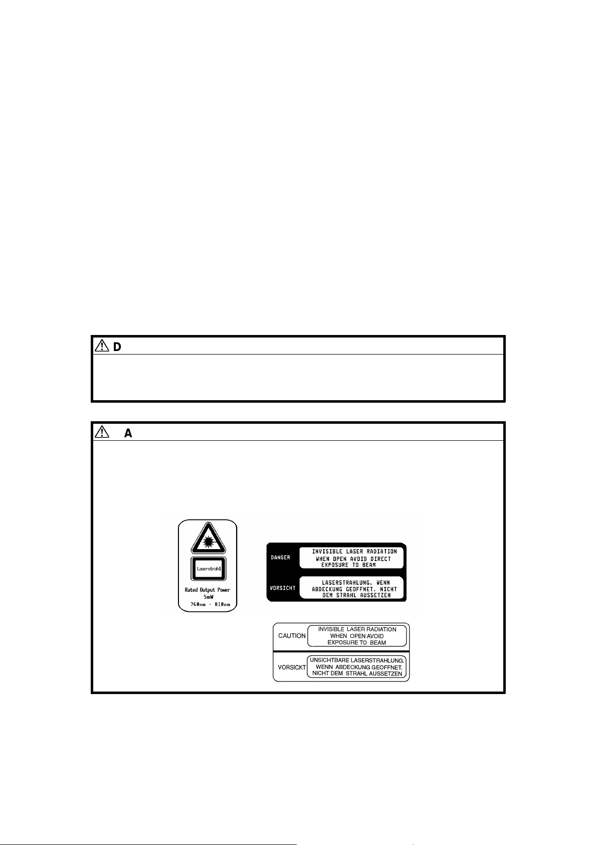
LASER SAFETY
The Center for Devices and Radiological Health (CDRH) prohibits the repair
of laser-based optical units in the field. The optical housing unit can only be
repaired in a factory or at a location with the requisite equipment. The laser
subsystem is replaceable in the field by a qualified Customer Engineer. The
laser chassis is not repairable in the field. Customer engineers are therefore
directed to return all chassis and laser subsystems to the factory or service
depot when replacement of the optical subsystem is required.
DANGER
Use of controls, or adjustment, or performance of procedures other
than those specified in this manual may result in hazardous radiation
exposure.
WARNING FOR LASER UNIT
DANGER:Turn off the main switch before at tempting any of the
procedures in the Laser Unit section. Laser beams can
seriously damage your eyes.
CAUTION MARKING:
A172/A199 ii SM

INTRODUCTION
The A172/A199 copier (product name: LILY) is based on the A109 copier
(DFC-ALPHA), the base copier.
This documentation gathers the A172/A199 differing points from the base
copier that service personnel will need to maintain this copier. Therefore, this
documentation should be treated as an insert to the base copier’s service
manual, although it has a separate binder. It should always be utilized along
with the base copier’s service manual.
NOTE:Please refer to page 1-9 for machine code/model number
information.
SM iii A172/A199


OVERALL MACHINE INFORMATION
SORTER A322
DETAILED DESCRIPTIONS
FILM PROJECTER UNIT A718
INSTALLATION
CONTROLLER INTERFACE A583
TAB POSITION 1
TAB POSITION 2TAB POSITION 3TAB POSITION 4
SERVICE TABLES
REPLACEMENT AND ADJUSTMENT
TROUBLESHOOTING
DUAL JOB FEEDER A610
TAB POSITION 5TAB POSITION 6
SORTER A322
TAB POSITION 7
TAB POSITION 8


OVERALL
MACHINE INFORMATION


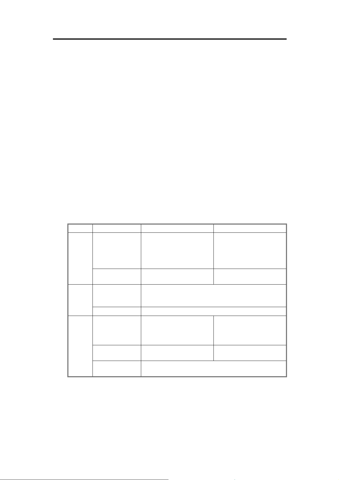
1. MACHINE CONFIGURATION
4
1
- Copier -
Item Machine Code Note No.
Copier
Dual Job Feeder
Sorter (15-bin)
Film Projector Unit
Holder
Language ROM
board
(for operation panel)
A172
A199
A610
A322
A718
A702-18
A654
(Not for US
version)
2
3
- Full System -
•
A172 is the edit version with a full color
operationpanel.
•
A199 is the non-edit version with a black &
white operation panel.
•
An English language ROM board is installed
in -*17/29/10/22/15 machines.
•
No language ROM board is installed in
-27/26 machines.
•
Common with A175/A176/A177/A191/A192
copiers.
•
A sorter adapter (A527) is required for
installation.
•
A holder (A702-18) is required for installation.
•
The holder can be installed independently as
an original table.
•
The following languages are available:
English (A4), German, French, Italian,
Spanish, (Universal).
Information
Overall Machine
5
1
2
3
4
5
—
*Note: -17 is for US version units.
Refer to page 1-9 for Machine Code / Model
Number information
SM 1-1 A172/A199
2. SPECIFICATIONS
2.1 SPECIFICATIONS
Specifications are subject to change without notice.
Configuration: Console
Copy Process: Dry electrostatic transfer system
Resolution: 400 dpi
Gradations: 256 gradations
Original Type: Sheet/book, object
Original Size: Maximum: A3 (lengthwise), 11" x 17" (lengthwise)
Original Alignment: Rear-left corner
Copy Paper Weight: • Paper Tray: 64 - 104.7 g/m2 or 17 - 28 lb
• Bypass Feed Tray: 64 - 157 g/m
2
or 17 - 42 lb
NOTE: With paper heavier tha n 10 4. 7 g/m2 or
28 lb, use the bypass feed tr ay an d
select Thick Paper mode.
Available Copy Paper Size:
Tray Paper Direction A4/A3 version LT/DLT version
1st /2nd
Tray
3rd Tray
Bypass
Feed
Tray
Lengthwise
Sideways
Lengthwise
Sideways
Lengthwise
Sideways
Non-standard
paper size
A3, A4, 8
8
" x 13"
1/4
" x 13" (F4),
1/2
A4, A5 11" x 8
A3, B4, A4, B5, A5, 11" x 17" (DLT), 11" x 15", 10" x 14",
" x 14" (LG), 8
8
1/2
" x 11" (LT), 8" x 10
8
1/2
A4, B5, A5, 11" x 8
" x 13" (F4), 8
1/2
" (LT), 8
1/2
A3, B4, A4, B5, A5, B6, A6 11" x 17" (DLT), 10" x 14",
A4, B5, A5, B6, 8
" x 11" 8
1/2
Horizontal direction: 148 - 432 mm or 5.8" - 17.0"
Vertical direction: 100 - 297 mm or 3.9" - 11.7"
11" x 17" (DLT), 11" x 15",
10" x 14", 8
1/2
8" x 13" (F),
8
" x 11" (LT),
1/2
8" x 10
8
1/2
", 8" x 10", 5
1/2
1/2
8
1/2
", 8" x 10"
1/2
" (LT),
1/2
" x 5
" x 5
" (HLT)
1/2
" x 13", 8" x 13" (F),
1/4
" x 8
1/2
" (HLT)
1/2
" x 11" (LT),
8" x 13" (F),
5
x 8
1/2
1/2
5
1/2
" (HLT)
1/2
" x 11" (LT),
" x 8
" (HLT)
1/2
" x 14" (LG),
" (HLT)
1/2
A172/A199 1-2 SM

Warm-up Time:
About 8 minutes (at 20°C or 68°F)
First Copy Time:
(A4 or 8
" x 11" sideways)
1/2
Copying Speed:
(Standard modes)
•
Full Color (4 scans): 15.5 seconds
•
Single Color:
Black, Yellow, Magenta, Cyan: 8.8 seconds
Red, Green, Blue, Orange, Light Green:
11.5 seconds.
NOTE: 1) When selecting OHP/Thick Paper
modes, copying speed is reduced.
2) After changing some modes, the first
copy time will take longer than usual.
•
Full Color (4 scans):
A4 or 8
" x 11" sideways: 6 copies/minute
1/2
A3 or 11" x 17": 3 copies/minute
•
Single Color (Black, Yellow, Magenta, Cyan):
A4 or 8
" x 11" sideways: 31 copies/minute
1/2
A3 or 11" x 17": 15 copies/minute
•
Single Color
(Red, Green, Blu e, Orange, Light Gr ee n) :
A4 or 8
" x 11" sideways: 10 copies/minute
1/2
A3 or 11" x 17": 5 copies/minute
Information
Overall Machine
NOTE: When selecting OHP/Thick Paper
modes, copying speed is reduced.
Non-reproduction Area:
•
Leading edge: 5 ± 2 mm or 0.2" ± 0.08"
•
Side: 2 ± 2 mm or 0.08" ± 0.08", Total less than
4 mm or 0.16"
•
Trailing edge: 2 ± 2 mm or 0.08" ± 0.08"
Copy Number Input: Number keys, 1 to 99
Automatic Reset: 1-minute standard setting; can also be set to 10
to 900 seconds in 1-second steps, or to no auto
reset.
Paper Feed: Paper Tray x 3
(500 sheets of paper each)
Bypass Feed Tray
(50 sheets of paper with paper lighter than
104.7 g/m2 or 28 lb)
SM 1-3 A172/A199
 Loading...