

Page 1
A283/A284
SUPPLEMENTAL SERVICE MANUAL
(To be used in conjunction with A230/A231/232 Service Manual)
000958MIU
RICOH GROUP COMPANIES
Page 2

Page 3

SERVICE MANUAL
A283/A284
RICOH GROUP COMPANIES
Page 4

Page 5

A283/A284
SERVICE MANUAL
000958MIU
Page 6

Page 7

It is the reader's responsibility when discussing the information contained within this
document to maintain a level of confidentiality that is in the best interest of Ricoh
Corporation and its member companies.
NO PART OF THIS DOCUMENT MAY BE REPRODUCED IN ANY
FASHION AND DISTRIBUTED WITHOUT THE PRIOR
PERMISSION OF RICOH CORPORATION.
All product names, domain names or product illustrations, including desktop images,
used in this document are trademarks, registered trademarks or the property of their
respective companies.
They are used throughout this book in an informational or editorial fashion only and for
the benefit of such companies. No such use, or the use of any trade name, or web
site is intended to convey endorsement or other affiliation with Ricoh products.
2000 RICOH Corporation. All rights reserved.
Page 8

Page 9

WARNING
The Service Manual contains information
regarding service techniques, procedures,
processes and spare parts of office equipment
distributed by Ricoh Corporation. Users of this
manual should be either service trained or
certified by successfully completing a Ricoh
Technical Training Program.
Untrained and uncertified users utilizing
information contained in this service manual to
repair or modify Ricoh equipment risk personal
injury, damage to property or loss of warranty
protection.
Ricoh Corporation
Page 10

Page 11

LEGEND
PRODUCT CODE COMPANY
GESTETNER RICOH SAVIN
A283 3235e Aficio 350e 9935DPE
A284 3245e Aficio 450e 9945DPE
DOCUMENTATION HISTORY
REV. NO. DATE COMMENTS
*
3/2000 Original Printing
Page 12

Page 13

A283/A284
TABLE OF CONTENTS
OVERALL INFORMATION
1. OVERALL MACHINE INFORMATION........................................1-1
1.1 SPECIFICATIONS.................................................................................... 1-1
1.2 PAPER EXIT TRAY SELECTION............................................................. 1-4
1.3 MACHINE CONFIGURATION.................................................................. 1-5
1.3.1 SYSTEM COMPONENTS ............................................................... 1-5
1.3.2 INSTALLABLE OPTION TABLE ...................................................... 1-7
1.4 MECHANICAL COMPONENT LAYOUT................................................... 1-8
1.5 PAPER PATH........................................................................................... 1-9
1.6 DRIVE LAYOUT ....................................................................................... 1-9
1.7 ELECTRICAL COMPONENT DESCRIPTIONS...................................... 1-10
1.8 BOARD STRUCTURE............................................................................ 1-14
1.8.1 BLOCK DIAGRAM......................................................................... 1-14
1.8.2 DESCRIPTIONS............................................................................ 1-15
DETAILED DESCRIPTIONS
2. DETAILED DESCRIPTIONS....................................................... 2-1
2.1 SCANNING............................................................................................... 2-1
2.1.1 OVERVIEW ..................................................................................... 2-1
2.2 IMAGE PROCESSING ............................................................................. 2-2
2.2.1 OVERVIEW ..................................................................................... 2-2
2.2.2 SBU ................................................................................................. 2-3
2.2.3 IMAGE PROCESSING .................................................................... 2-4
INSTALLATION
3. INSTALLATION PROCEDURE...................................................3-1
3.1 INSTALLATION REQUIREMENTS .......................................................... 3-1
3.1.1 ENVIRONMENT .............................................................................. 3-1
3.1.2 MACHINE LEVEL............................................................................ 3-1
3.1.3 MINIMUM SPACE REQUIREMENTS.............................................. 3-2
3.1.4 POWER REQUIREMENTS.............................................................. 3-3
3.2 INSTALLATION FLOW CHART................................................................ 3-4
3.3 COPIER INSTALLATION.......................................................................... 3-5
3.3.1 ACCESSORY CHECK..................................................................... 3-5
3.3.2 INSTALLATION PROCEDURE........................................................ 3-6
3.4 PAPER TRAY UNIT INSTALLATION..................................................... 3-11
3.4.1 ACCESSORY CHECK................................................................... 3-11
3.4.2 INSTALLATION PROCEDURE...................................................... 3-12
SM i A283/A284
Page 14

3.5 1-BIN TRAY UNIT INSTALLATION ........................................................ 3-16
3.5.1 ACCESSORY CHECK................................................................... 3-16
3.5.2 INSTALLATION PROCEDURE...................................................... 3-17
3.6 BRIDGE UNIT INSTALLATION.............................................................. 3-22
3.6.1 ACCESSORY CHECK................................................................... 3-22
3.6.2 INSTALLATION PROCEDURE...................................................... 3-23
3.7 AUTO REVERSE DOCUMENT FEEDER INSTALLATION.................... 3-25
3.7.1 ACCESSORY CHECK................................................................... 3-25
3.7.2 INSTALLATION PROCEDURE...................................................... 3-26
3.8 LCT INSTALLATION .............................................................................. 3-28
3.8.1 ACCESSORY CHECK................................................................... 3-28
3.8.2 INSTALLATION PROCEDURE...................................................... 3-29
3.9 1,000-SHEET FINISHER INSTALLATION.............................................. 3-31
3.9.1 ACCESSORY CHECK................................................................... 3-31
3.9.2 INSTALLATION PROCEDURE...................................................... 3-32
3.10 3,000-SHEET FINISHER INSTALLATION............................................ 3-35
3.10.1 ACCESSORY CHECK................................................................. 3-35
3.10.2 INSTALLATION PROCEDURE.................................................... 3-36
3.11 PUNCH UNIT INSTALLATION............................................................. 3-39
3.11.1 ACCESSORY CHECK................................................................. 3-39
3.11.2 INSTALLATION PROCEDURE.................................................... 3-40
3.12 PLATEN COVER INSTALLATION........................................................ 3-43
3.13 KEY COUNTER INSTALLATION ......................................................... 3-44
3.14 ANTI-CONDENSATION HEATER........................................................ 3-46
3.15 TRAY HEATER..................................................................................... 3-48
3.16 TRAY HEATER (OPTIONAL PAPER TRAY UNIT) .............................. 3-49
SERVICE TABLES
4. SERVICE TABLES......................................................................4-1
4.1 SERVICE PROGRAM MODE TABLES.................................................... 4-1
4.1.1 TEST PATTERN PRINTING (SP2-902)......................................... 4-42
4.1.2 INPUT CHECK............................................................................... 4-43
4.1.3 OUTPUT CHECK........................................................................... 4-47
4.1.4 SYSTEM PARAMETER AND DATA LISTS (SMC LISTS)............. 4-48
4.1.5 NIP BAND WIDTH ADJUSTMENT (SP1-109)............................... 4-49
4.1.6 MEMORY ALL CLEAR (SP5-801)................................................. 4-50
4.1.7 SOFTWARE RESET...................................................................... 4-51
4.1.8 SYSTEM SETTING AND COPY SETTING (UP MODE) RESET... 4-51
4.1.9 NVRAM DATA DOWNLOAD......................................................... 4-52
4.2 PROGRAM DOWNLOAD....................................................................... 4-54
4.3 USER PROGRAM MODE....................................................................... 4-58
4.3.1 HOW TO ENTER AND EXIT UP MODE........................................ 4-58
4.3.2 UP MODE TABLE.......................................................................... 4-58
4.4 TEST POINTS/DIP SWITCHES/LEDS................................................... 4-60
4.4.1 DIP SWITCHES............................................................................. 4-60
4.4.2 TEST POINTS............................................................................... 4-60
4.4.3 LEDS ............................................................................................. 4-61
A283/A284 ii SM
Page 15

4.5 SPECIAL TOOLS AND LUBRICANTS ................................................... 4-61
4.5.1 SPECIAL TOOLS........................................................................... 4-61
4.5.2 LUBRICANTS................................................................................ 4-61
PREVENTIVE MAINTENANCE
5. PREVENTIVE MAINTENANCE SCHEDULE............................... 5-1
5.1 PM TABLE................................................................................................ 5-1
REPLACEMENT AND ADJUSTMENT
6. REPLACEMENT AND ADJUSTMENT........................................6-1
6.1 SCANNER UNIT....................................................................................... 6-1
6.1.1 EXPOSURE GLASS........................................................................ 6-1
6.1.2 SCANNER EXTERIOR/OPERATION PANEL................................. 6-2
6.1.3 LENS BLOCK/SBU ASSEMBLY...................................................... 6-3
6.1.4 SCANNER MOTOR......................................................................... 6-4
6.1.5 SIB/LAMP STABILIZER................................................................... 6-5
6.2 LASER UNIT............................................................................................. 6-6
6.2.1 CAUTION DECAL LOCATIONS...................................................... 6-6
6.2.2 LASER UNIT.................................................................................... 6-7
6.2.3 LASER BEAM PITCH ADJUSTMENT ............................................. 6-8
6.3 COPY ADJUSTMENTS: PRINTING/SCANNING..................................... 6-9
6.3.1 PRINTING........................................................................................ 6-9
6.3.2 SCANNING.................................................................................... 6-12
6.3.3 ADF IMAGE ADJUSTMENT.......................................................... 6-14
TROUBLESHOOTING
7. TROUBLESHOOTING................................................................. 7-1
7.1 SERVICE CALL CONDITIONS................................................................. 7-1
7.1.1 SUMMARY....................................................................................... 7-1
7.1.2 SC CODE DESCRIPTIONS............................................................. 7-2
7.2 ELECTRICAL COMPONENT DEFECTS................................................ 7-24
7.2.1 SENSORS..................................................................................... 7-24
7.2.2 SWITCHES.................................................................................... 7-25
7.3 BLOWN FUSE CONDITIONS................................................................. 7-26
SCANNER KIT B359
1. OVERALL MACHINE INFORMATION........................................8-1
1.1 SPECIFICATIONS.................................................................................... 8-1
1.1.1 SCANNER CONTROL BOARD....................................................... 8-1
1.1.2 DRAM SIMM.................................................................................... 8-2
1.2 SOFTWARE ............................................................................................. 8-3
1.2.1 SCANNER DRIVERS ...................................................................... 8-3
1.2.2 SCANNER UTILITIES...................................................................... 8-3
SM iii A283/A284
Page 16

1.2.3 SCANNER UTILITY (OPTION)........................................................ 8-3
2. DETAILED SECTION DESCRIPTIONS ....................................... 8-4
2.1 HARDWARE OVERVIEW ........................................................................ 8-4
2.2 SCANNER FUNCTIONS .......................................................................... 8-6
2.2.1 SELF DIAGNOSTICS...................................................................... 8-6
2.2.2 IMAGE PROCESSING IN THE SCANNER CONTROLLER............ 8-6
3. INSTALLATION PROCEDURE...................................................8-7
4. SERVICE TABLE ...................................................................... 8-11
4.1 SERVICE PROGRAM MODE................................................................. 8-11
4.1.1 SERVICE PROGRAM ACCESS PROCEDURE............................ 8-11
4.1.2 SERVICE PROGRAM MODE TABLES......................................... 8-11
4.2 DOWNLOADING NEW SOFTWARE...................................................... 8-13
4.2.1 SOFTWARE DOWNLOAD PROCEDURE..................................... 8-13
4.2.2 ERROR MESSAGES DURING THE SOFTWARE DOWNLOAD .. 8-14
5. REPLACEMENT AND ADJUSTMENT...................................... 8-15
5.1 PRECAUTION........................................................................................ 8-15
5.2 NOTE FOR REPLACING THE SCANNER CONTROLLER BOARD...... 8-15
6. TROUBLESHOOTING............................................................... 8-16
6.1 SERVICE CALL CONDITION................................................................. 8-16
6.1.1 SC CODE DESCRIPTIONS........................................................... 8-16
6.2 LEDS...................................................................................................... 8-17
A283/A284 iv SM
Page 17

FAX UNIT A874
TABLE OF CONTENTS
1. OVERALL MACHINE INFORMATION........................................1-1
1.1 SPECIFICATIONS.................................................................................... 1-1
1.2 FEATURES............................................................................................... 1-2
1.2.1 FEATURES LIST............................................................................. 1-2
1.2.2 CAPABILITIES OF PROGRAMMABLE ITEMS ............................... 1-5
1.3 OVERALL MACHINE CONTROL............................................................. 1-6
1.3.1 SYSTEM CONTROL........................................................................ 1-6
1.3.2 POWER DISTRIBUTION AND CONTROL...................................... 1-7
1.3.3 MEMORY BACK-UP........................................................................ 1-7
1.4 VIDEO DATA PATH.................................................................................. 1-8
1.4.1 TRANSMISSION.............................................................................. 1-8
1.4.2 RECEPTION.................................................................................. 1-10
1.4.3 PC FAX COMMUNICATION.......................................................... 1-11
1.4.4 SCANNING AND PRINTING ......................................................... 1-13
2. DETAILED SECTION DESCRIPTIONS.......................................2-1
2.1 AUTOMATIC SERVICE CALLS................................................................ 2-1
2.1.1 SERVICE CALL CONDITIONS........................................................ 2-1
2.1.2 PERIODIC SERVICE CALL............................................................. 2-3
2.1.3 PM CALL.......................................................................................... 2-3
2.1.4 EFFECTIVE TERM OF SERVICE CALLS....................................... 2-3
2.2 SCANNING FEATURES........................................................................... 2-4
2.2.1 CREATE MARGIN TRANSMISSION............................................... 2-4
2.3 PRINTING FEATURES............................................................................. 2-5
2.3.1 REDUCTION FOR JOURNAL PRINTING ....................................... 2-5
2.3.2 JOURNAL LINE TYPE SORT PRINTING........................................ 2-5
2.3.3 PRINTING LISTS & REPORTS ON A5/HLT SIZE PAPER.............. 2-6
2.3.4 REDUCTION OF THE SAMPLE IMAGE ON REPORTS................. 2-7
2.4 LINE TYPE CHANGE............................................................................... 2-8
2.5 PCBS...................................................................................................... 2-10
2.5.1 FCU................................................................................................ 2-10
2.5.2 NCU (US)....................................................................................... 2-12
2.5.3 EXFUNC BOARD .......................................................................... 2-13
3. INSTALLA T ION...........................................................................3-1
3.1 INSTALLATION PROCEDURE................................................................. 3-1
3.1.1 FAX UNIT......................................................................................... 3-1
3.1.2 ISDN UNIT....................................................................................... 3-6
3.1.3 FAX FUNCTION .............................................................................. 3-8
3.1.4 PC-FAX EXPANDER TYPE 450E ................................................. 3-10
3.1.5 STAMP UNIT................................................................................. 3-13
3.1.6 HANDSET...................................................................................... 3-16
SM v A283/A284
Page 18

4. SERVICE TABLES......................................................................4-1
4.1 SERVICE LEVEL FUNCTIONS................................................................ 4-1
4.1.1 HOW TO ENTER AND EXIT THE FAX SERVICE MODE............... 4-1
4.1.2 BIT SWITCH PROGRAMMING (FUNCTION 01)............................. 4-1
4.1.3 SYSTEM PARAMETER LISTS (FUNCTION 02)............................. 4-2
4.1.4 FCU ROM VERSION DISPLAY (FUNCTION 02)............................ 4-4
4.1.5 MODEM PROGRAM VERSION DISPLAY (FUNCTION 02)............ 4-4
4.1.6 ERROR CODE DISPLAY (FUNCTION 03)...................................... 4-4
4.1.7 SERVICE MONITOR REPORT (FUNCTION 04)............................. 4-4
4.1.8 G3 PROTOCOL DUMP LIST (FUNCTION 05)................................ 4-5
4.1.9 G4 PROTOCOL DUMP LIST (FUNCTION 05)................................ 4-5
4.1.10 PC PROTOCOL DUMPLIST (FUNCTION 05)............................... 4-6
4.1.11 RAM DISPLAY AND REWRITE (FUNCTION 06).......................... 4-6
4.1.12 NCU PARAMETERS (FUNCTION 06)........................................... 4-7
4.1.13 RAM DUMP (FUNCTION 06)......................................................... 4-7
4.1.14 RAM CLEAR (FUNCTION 07)....................................................... 4-8
4.1.15 FCU REBOOT ............................................................................... 4-8
4.1.16 SERVICE STATION FAX NUMBER (FUNCTION 09)....................4-8
4.1.17 SERIAL NUMBER (FUNCTION 10)............................................... 4-9
4.1.18 MODEM TEST (FUNCTION 11).................................................... 4-9
4.1.19 V.34 MODEM TEST (FUNCTION 11).......................................... 4-10
4.1.20 DTMF TEST (FUNCTION 11)...................................................... 4-10
4.1.21 RINGER TEST (FUNCTION 11).................................................. 4-11
4.1.22 MEMORY TEST (FUNCTION 11)................................................ 4-11
4.1.23 DIU TEST (FUNCTION 11).......................................................... 4-12
4.1.24 FILE PRINTOUT (FUNCTION 13)............................................... 4-12
4.1.25 JOURNAL PRINTOUT (FUNCTION 14)...................................... 4-13
4.1.26 USAGE LOG PRINTOUT (FUNCTION 15).................................. 4-13
4.1.27 DATA TRANSFER (FUNCTION 16)............................................ 4-13
4.2 BIT SWITCHES...................................................................................... 4-14
4.2.1 SYSTEM SWITCHES.................................................................... 4-14
4.2.2 SCANNER SWITCHES.................................................................. 4-28
4.2.3 PRINTER SWITCHES................................................................... 4-33
4.2.4 COMMUNICATION SWITCHES.................................................... 4-39
4.2.5 G3 SWITCHES.............................................................................. 4-49
4.3 NCU PARAMETERS .............................................................................. 4-57
4.4 DEDICATED TRANSMISSION PARAMETERS..................................... 4-68
4.4.1 PROGRAMMING PROCEDURE................................................... 4-68
4.4.2 PARAMETERS.............................................................................. 4-69
4.5 SERVICE RAM ADDRESSES................................................................ 4-73
5. PREVENTIVE MAINTENANCE...................................................5-1
5.1 SPECIAL TOOLS AND LUBRICANTS ..................................................... 5-1
5.2 PM TABLE................................................................................................ 5-1
A283/A284 vi SM
Page 19

6. REPLACEMENT AND ADJUSTMENT........................................ 6-1
6.1 PRECAUTION.......................................................................................... 6-1
6.2 NCU AND SPEAKER................................................................................ 6-1
6.3 FCU .......................................................................................................... 6-2
6.3.1 REMOVAL ....................................................................................... 6-2
6.3.2 SRAM DATA RESTORE FROM FCU.............................................. 6-2
6.3.3 SRAM DATA RESTORE FROM FLASH CARD BACKUP............... 6-4
6.4 ROM UPDATE.......................................................................................... 6-7
6.4.1 FCU ROM DOWNLOAD.................................................................. 6-7
6.4.2 FCU ROM UPLOAD......................................................................... 6-9
6.4.3 SRAM BACKUP TO A FLASH MEMORY CARD........................... 6-11
6.5 DATA ADDRESS RANGES ON THE CARD.......................................... 6-13
6.5.1 FCU AND BICU ROM DATA.......................................................... 6-13
6.5.2 MODEM ROM AND SRAM DATA ................................................. 6-13
7. TROUBLESHOOTING.................................................................7-1
7.1 ERROR CODES....................................................................................... 7-1
7.2 FAX SC CODES..................................................................................... 7-10
7.2.1 OVERVIEW.................................................................................... 7-10
7.2.2 SC1201.......................................................................................... 7-10
7.2.3 SC1207.......................................................................................... 7-10
7.2.4 FAX SC CODE TABLE.................................................................. 7-11
SM vii A283/A284
Page 20

Page 21

IMPORTANT SAFETY NOTICES
PREVENTION OF PHYSICAL INJURY
1. Before disassembling or assembling parts of the copier and peripherals,
make sure that the copier power cord is unplugged.
2. The wall outlet should be near the copier and easily accessible.
3. Note that some components of the copier and the paper tray unit are
supplied with electrical voltage even if the main power switch is turned off.
4. If any adjustment or operation check has to be made with exterior covers off
or open while the main switch is turned on, keep hands away from electrified
or mechanically driven components.
5. If the Start key is pressed before the copier completes the warm-up period
(the Start key starts blinking red and green alternatively), keep hands away
from the mechanical and the electrical components as the copier starts
making copies as soon as the warm-up period is completed.
6. The inside and the metal parts of the fusing unit become extremely hot while
the copier is operating. Be careful to avoid touching those components with
your bare hands.
HEALTH SAFETY CONDITIONS
Toner and developer are non-toxic, but if you get either of them in your eyes by
accident, it may cause temporary eye discomfort. Try to remove with eye drops
or flush with water as first aid. If unsuccessful, get medical attention.
OBSERVANCE OF ELECTRICAL SAFETY STANDARDS
1. The copier and its peripherals must be installed and maintained by a
customer service representative who has completed the training course on
those models.
2. The NVRAM on the system control board has a lithium battery which can
explode if replaced incorrectly. Replace the NVRAM only with an identical
one. The manufacturer recommends replacing the entire NVRAM. Do not
recharge or burn this battery. Used NVRAM must be handled in accordance
with local regulations.
Page 22

SAFETY AND ECOLOGICAL
1. Do not incinerate toner bottles or used toner. Toner dust may ignite suddenly
when exposed to an open flame.
2. Dispose of used toner, developer, and organic photoconductors in
accordance with local regulations. (These are non-toxic supplies.)
3. Dispose of replaced parts in accordance with local regulations.
4. When keeping used lithium batteries in order to dispose of them late r, do not
put more than 100 batteries per sealed box. Storing larger numbers or not
sealing them apart may lead to chemical reactions and heat build-up.
NOTES
FOR DISPOSAL
LASER SAFETY
The Center for Devices and Radiological Health (CDRH) prohibits the repair of
laser-based optical units in the field. The optical housing unit can only be repaired
in a factory or at a location with the requisite equipment. The laser subsystem is
replaceable in the field by a qualified Customer Engineer. The laser chassis is not
repairable in the field. Customer engineers are therefore directed to return all
chassis and laser subsystems to the factory or service depot when replacement of
the optical subsystem is required.
WARNING
Use of controls, or adjustment, or performance of procedures other than
those specified in this manual may result in hazardous radiation exposure.
WARNING
WARNING: Turn off the main switch before attempting any of the
procedures in the Laser Unit section. Laser beams can
seriously damage your eyes.
CAUTION MARKING:
Page 23

OVERALL INFORMATION A283/A284
OVERALL INFORMATION A874
DETAILED DESCRIPTIONS A283/A284
DETAILED DESCRIPTIONS A874
INSTALLATION A283/A284
INS TALL AT I O N A8 7 4
SERVICE TABLES A283/A284
SERVICE TABLES A874
TAB
POSITION 1
TAB
POSITION 2
TAB
POSITION 3
TAB
POSITION 4
PREVENTIVE MAINTENANCE A283/A284
PREVENTIVE MAINTENANCE A874
REPLACEMENT AND ADJUSTMENT A283/A284
REPLACEMENT AND ADJUSTMENT A874
TROUBLESHOOTING A283/A284
TROUBLESHOOTING A874
SCANNER KIT B359
TAB
POSITION 5
TAB
POSITION 6
TAB
POSITION 7
TAB
POSITION 8
Page 24

Page 25

OVERALL INFORMATION
Page 26

Page 27

1. OVERALL MACHINE INFORMATION
SPECIFICATIONS
1.1 SPECIFICATIONS
The “*” mark indicates differences between these machines and the
A230/A231/A232 machines.
A283 (35 cpm) A284 (45 cpm) Note
Configuration: Desktop
Copy Process: Dry electrostatic transfer system
Original: Sheet/Book
Original Size
Copy Paper
Size:
Copy Paper
Weight:
Reproduction
Ratios:
Zoom: Both versions:
Copying Speed 35 cpm
Resolution*: Scanning and Printing: 600 dpi
Gradation: Scanning and Printing: 256 levels
Warm-up Time: Less than 85 s Less than 100 s
First Copy Time
(1st Tray):
Copy Number
Input:
Maximum A3/11
Maximum:
A3/11
Minimum:
A5/5.5
A6/5.5" x 8.5" lengthwise (By-pass)
Paper Tray/Duplex:
64 - 105 g/m
By-pass:
52 - 157 g/m
7R5E
Metric version (%):
400, 200, 141, 122, 115,
100, 93, 87, 82, 71, 65,
50, 25
Inch version (%):
400, 200, 155, 129, 121,
100, 93, 85, 78, 73, 65,
50, 25
25% to 400% in 1%
steps
(A4/11
19 cpm
(A3/11
Less than 3.9 s Less than 3.2 s
Ten-key pad, 1 to 999 Count up or
x 17
"
x 8.5" lengthwise (Paper tray / Duplex)
"
x 8.5" sideways)
"
x 17")
"
x 17
"
"
"
2
, 20 – 28 lb
2
, 16 – 42 lb
7R5E
Metric version (%):
400, 200, 141, 122, 115,
100, 93, 87, 82, 71, 65,
50, 35
Inch version (%):
400, 200, 155, 129, 121,
100, 93, 85, 78, 73, 65,
50, 32
Metric version:
35% to 400% in 1%
steps
Inch version:
32% to 400% in 1%
steps
45 cpm
(A4/11
22 cpm
(A3/11
x 8.5" sideways)
"
x 17")
"
Full size
Repeat copy
mode
23°C, 73°F
A4/11
sideways (1st
paper tray)
count down
x 8.5
"
Overall
Information
"
SM 1-1 A283/A284
Page 28

SPECIFICATIONS
A283 (35 cpm) A284 (45 cpm) Note
Manual Image
Density
Selection:
Automatic
Reset:
Auto Shut Off:
Copy Paper
Capacity:
Copy Tray
Capacity:
Toner
Replenishment:
Toner Yield:
Power Source: North America
Dimensions
(W x D x H)
Weight: 75 kg (166 lb)
5 steps
60 s is the standard setting; it can be changed with the
UP mode.
60 min. is the standard setting; it can be changed with
the UP mode.
Paper Tray:
500 sheets (stack thickness up to 56 mm, 2.2
By-pass Feed:
50 sheets (stack thickness up to 5.5 mm, 0.2
A4/11
A3/B4/8.5
Cartridge excha nge (7 00 g /cartridge)
27k copies
670 x 640 x 720 mm (26.4
x 8.5": 500 sheets
"
x 14"/11" x 17": 250 sheets
"
(A4 sideways, 6% full black, 1 to 1 copying, ADS
mode)
120V/60Hz, More than 12 A
x 25.2" x 28.3")
"
"
)
"
) x 2
Standard
copy tray
Without
options
Power Consumption:
Mainframe only
A283 A284 Note
Maximum Less than 1.44 kW Less than 1.44 kW
Copying Less than 1.05 kW Less than 1.05 kW
Warm-up Less than 1.00 kW Less than 1.05 kW
Stand-by Less than 200 Wh Less than 220 Wh
System
A283 A284 Note
Maximum Less than 1.44 kW Less than 1.44 kW
Copying Less than 1.15 kW Less than 1.15 kW
Warm-up Less than 1.00 kW Less than 1.05 kW
Stand-by Less than 200 Wh Less than 230 Wh
Without the optional
heaters, fax unit,
and printer
controller.
A283/A284 1-2 SM
Page 29

Noise Emission:
Copying
A283
A284
Stand-by
A283
A284
SPECIFICATIONS
Mainframe Only Full System
52 dB(A) or less
56 dB(A) or less
27 dB(A) or less
27 dB(A) or less
60 dB(A) or less
62 dB(A) or less
28 dB(A) or less
28 dB(A) or less
Overall
Information
NOTE:
1) The above measurements were made in accordance with ISO 7779.
2) Full system measurements do not include the optional fax unit and the
printer controller.
3) In the above stand-by condition, the polygon motor is not rotating.
SM 1-3 A283/A284
Page 30
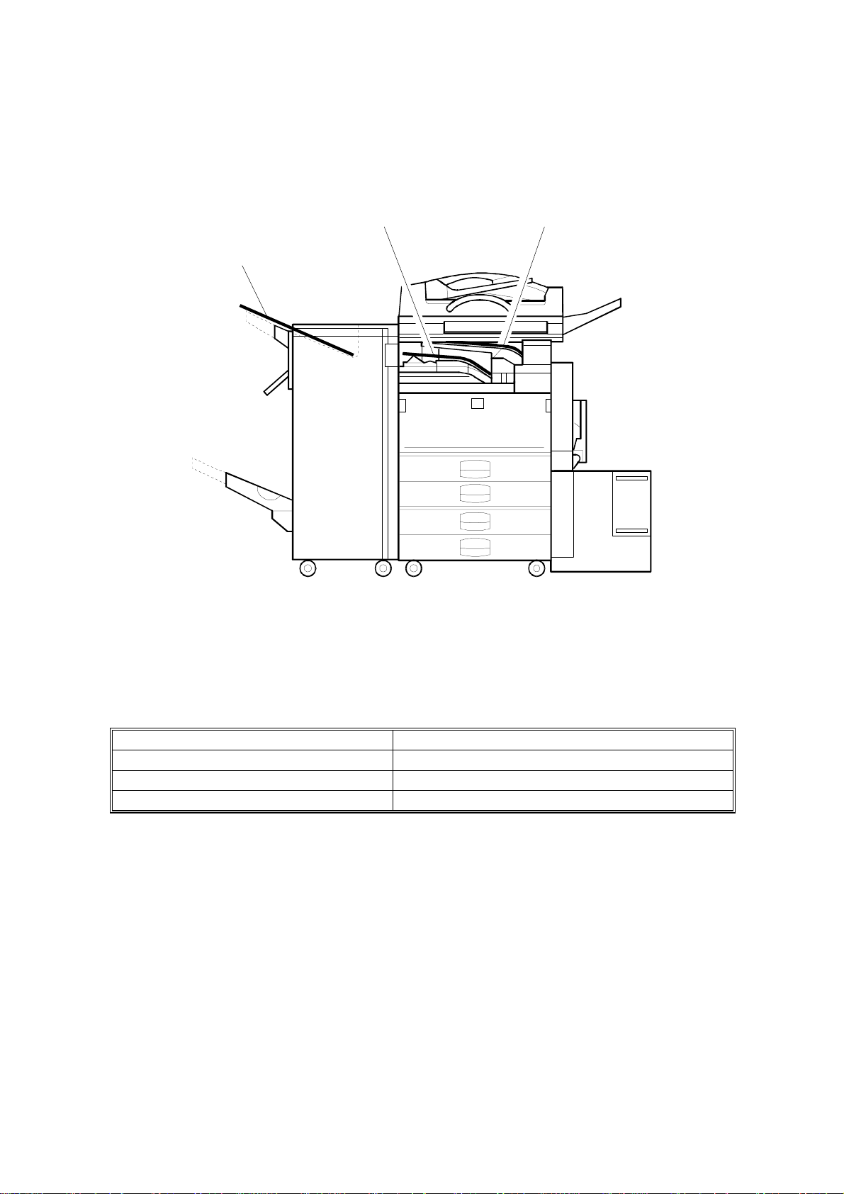
PAPER EXIT TRAY SELECTION
1.2 PAPER EXIT TRAY SELECTION
[A] A4, LT [B] A3, LT
[C] Longer than A3, DLT
A284V508.WMF
The machine allows selection between the paper tray exit trays: Int. Tray [A]
(standard output tray), Int. Tray 2 [B] (optional one-bin tray), and Ext. Tray [C]
(finisher or optional external output tray). If the sub-scan length is more than 330
mm, the exit tray is as shown below, if the relevant options have been installed.
Installed options Exit tray for paper longer than 330 mm
Bridge unit & Finisher (1,000-sheet) Int. Tray [A]
Bridge unit & Finisher (3,000-sheet) Ext. Tray [C]: The finisher upper tray
Bridge unit & optional ext. output tray Ext. Tray [C]: Ext. output tray
A283/A284 1-4 SM
Page 31

1.3 MACHINE CONFIGURATION
1.3.1 SYSTEM COMPONENTS
MACHINE CONFIGURATION
Overall
Information
11 1
9
10
2
3
8
5
7
4
6
A284V502.WMF
SM 1-5 A283/A284
Page 32

MACHINE CONFIGURATION
Symbol: U: Unique option, C: Option also used with other products
Version Item Machine Code No. Note
Copier (A283) A283 5
Copier (A284) A284 5
ARDF (Option) A680 2 C
Platen Cover (Option) A381 1 C
Paper Tray Unit (Option) A682 6 C
LCT (Option) A683 4 C
1-bin Tray (Option) A684 3 C
Copy
Fax
Printer
Scanner
Bridge Unit (Option) A688 10 C
1000-sheet Finisher (Option) A681 8 C
3000-sheet Finisher
(Option – A284 only)
Punch Unit
(Option for 3000-sheet Finisher)
External Output Tray (Option) A825 9 C
Key Counter Bracket (Option) A674 11 C
Expansion Box (Option) A872 --- U
Fax Unit (Option) A874 --- U
ISDN Unit (Option) A816 --- C
RAM SIMM (Option) --- --400-dpi High Resolution (Option) A892 --- D
PC-Fax Expander B368 --- U
Handset (Option) A646 --- C
Stamp Unit (Option) A813 --- C
Printer Controller B358 --- U
PostScript Kit A854 --- C
Hard Disk A853 --- C
Network Interface Board A855 --- C
Mailbox G909 --- C
Mailbox Bridge Unit G912 --- C
RAM SIMM --- --Scanner Kit B359 --- U
RAM SIMM --- ---
A812-17 (3 holes)
A812-27 (2 holes)
A697 7 C
--- C
Symbol: U: Unique options C: Option also used with A230/A231/A232
D: Option also used with A265/A267
A283/A284 1-6 SM
Page 33

1.3.2 INSTALLABLE OPTION TABLE
Copier options
MACHINE CONFIGURATION
Option A283 A284 Note
ARDF
Platen Cover
Paper Tray Unit
LCT
1-bin Tray
Bridge Unit
1,000-sheet Finisher
3,000-sheet Finisher
Punch Unit
External Output Tray
Key Counter Bracket
Expansion Box
Printer options
| = Available, ∆ = Requires another option, X = Not available
||
||
||
∆ ∆
||
||
∆ ∆
X
X
∆ ∆
||
||
∆
∆
Requires the paper tray unit.
Requires the paper tray unit
and bridge unit.
Requires the paper tray unit
and bridge unit.
Requires the 3000-sheet
finisher.
Requires the bridge unit.
It is required only when the
fax option and/or printer
option is installed.
Overall
Information
Option A283 A284 Note
PostScript Kit
Hard Disk
Network Interface
Board
Mailbox
Mailbox Bridge Unit
RAM SIMM
|
= Available,
||
||
||
∆ ∆
∆ ∆
||
∆
= Requires another option
Requires the paper tray unit.
Requires the mailbox.
Fax options and scanner kits
All options for the fax unit are available when the fax unit has been installed.
Relationship between main machine, mailbox, and finisher
|
= Available, X = Not available
Model Mailbox 1000-sheet Finisher 3000-sheet Finisher
A283
A284
Installed
Not Installed
Installed
Not Installed
XX
|
X
||
X
|
SM 1-7 A283/A284
Page 34

MECHANICAL COMPONENT LAYOUT
1.4 MECHANICAL COMPONENT LAYOUT
321 654 987
10
42
41
40
39
38
37
36
11
12
13
14
15
16
17
18
19
20
21
23
24
25
26
22
27
28
29
31 3033 3235 34
A284V503.WMF
A283/A284 1-8 SM
Page 35

PAPER PATH
1. Exposure Glass
2. 2nd Mirror
3. Original Width Sensors
4. 1st Mirror
5. Exposure Lamp
6. Original Length Sensors
7. Lens
8. SBU
9. Scanner Motor
10. Hot Roller
11. Entrance Sensor
12. Inverter Gate
13. Inverter Roller
14. Pressure Roller
15. Transfer Belt Cleaning Blade
22. By-pass Tray
23. Pick-up Roller
24. Paper End Sensor
25. Paper Feed Roller
26. Separation Roller
27. Upper Relay Roller
28. Feed Roller
29. Separation Roller
30. Pick-up Roller
31. Bottom Plate
32. Development Unit
33. Charge Roller
34. Fθ Mirror
35. Barrel Toroidal Lens (BTL)
36. Polygonal Mirror Motor
Overall
Information
16. Upper Transport Roller
17. Transfer Belt
18. OPC Drum
19. Registration Roller
20. Lower Transport Roller
21. Exit Sensor
37. Laser Unit
38. Toner Supply Bottle Holder
39. Exit Junction Gate
40. Exit Roller
41. Paper Exit Sensor
42. 3rd Mirror
1.5 PAPER PATH
The paper path is the same as for A230/A231/A232 machines.
1.6 DRIVE LAYOUT
The drive layout is the same as for A230/A231/A232 machines.
SM 1-9 A283/A284
Page 36

ELECTRICAL COMPONENT DESCRIPTIONS
1.7 ELECTRICAL COMPONENT DESCRIPTIONS
Refer to the electrical component layout and the point-to-point diagram on the
waterproof paper in the pocket for the locations of these components.
Symbol
Printed Circuit Boa rds
PCB1 58
PCB2 55
PCB3 61
PCB4 62
PCB5 63
PCB6 9
PCB7 7
PCB8 11
PCB9 4 Lamp Stabilizer Provides dc power to the exposure lamp.
PCB10 19
PCB11 54
PCB12 65
Index
No.
Description Note
BICU (Base Engine &
Image Control Unit)
PSU
(Power Supply Unit)
IOB
(Input/Output Board)
Paper Feed Control
(PFB)
High Voltage Supply Supplies high voltage to the drum charge
SBU
(Sensor Board Unit)
SIB
(Scanner Interface
Board)
Operation Panel Controls the LCD and LED matrix and
LDDR
(Laser Diode Driver)
SIFB (Scanner
Interface Board)
Main (Duplex)
Controls all copier functions both directly and
through other control boards.
Provides dc power to the system and ac
power to the fusing lamp and optional
heaters.
Controls the mechanical parts of the printer
(excluding the paper feed section), and the
fusing lamp power.
Controls the mechanical parts of all paper
feed sections.
roller, development roller, and transfer belt.
Contains the CCD, and outputs a video
signal to the BICU board.
Controls the scanner carriages and passes
signals from the scanner unit to the BICU
board.
monitors the key matrix.
Controls the laser diode.
Passes signals between the SBU and BICU
boards.
Controls the duplex unit and communicates
with the copier.
Motors
M1 35 Main Drives the main body components.
M2 8 Scanner Drive Drives the 1st and 2nd scanners.
M3 45 Tr ay Lift Raises the bottom plate in the paper tray.
M4 22 Polygonal Mirror Turns the polygonal mirror.
M5 20
M6 36 Cooling Fan Removes heat from the main PCBs.
M7 37 Exhaust Fan Removes heat from around the fusing unit.
M8 34
M9 56 PSU Cooling Fan Removes heat from the PSU.
M10 64 Inverter (Duplex) Drives the duplex inverter roller.
M11 66
A283/A284 1-10 SM
LD Positioning
Toner Supply Rotates the toner bottle to supply toner to the
Transport (Duplex) Drives the duplex upper and lower transport
Rotates the LD unit to adjust the LD beam
pitch when a different resolution is selected.
development unit.
rollers.
Page 37

ELECTRICAL COMPONENT DESCRIPTIONS
Symbol
Index
No.
Description Note
Sensors
S1 2
Scanner Home
Position
Informs the CPU when the 1st and 2nd
scanners are at the home position.
Platen Cover Informs the CPU whether the platen cover is
S2 3
up or down (related to APS/ARE functions).
ARE: Auto Reduce and Enlarge
S3 12
S4 5
S5 6
S6 21
S7 17
Original Width Detects the width of the original. This is one
of the APS (Auto Paper Select) sensors.
Original Length-1 Detects the length of the original. This is one
of the APS (Auto Paper Select) sensors.
Original Length-2 Detects the length of the original. This is one
of the APS (Auto Paper Select) sensors.
LD Unit Home
Position
Informs the CPU when the LD unit is at the
home positon.
Toner Density (TD) Detects the amount of toner inside the
development unit.
S8 24 Paper Exit Detects misfeeds.
Registration Detects the leading edge of the copy paper
S9 27
to determine the stop timing of the paper
feed clutch, and detects misfeeds.
Image Density (ID) Detects the density of various patterns and
S10 26
the reflectivity of the drum for process
control.
S11 28
S12 30
S13 29
S14 31
Upper Paper Height Detects when the paper in the upper paper
tray is at the feed height.
Lower Paper Height Detects when the paper in the lower paper
tray is at the feed height.
Upper Paper End Informs the CPU when the upper paper tray
runs out of paper.
Lower Paper End Inform s the CPU when the lower paper tray
runs out of paper.
S15 33 Upper Relay Detects misfeeds.
S16 32 Lower Relay Detects misfeeds.
S17 48
S18 46
S19 38
S20 18
S21 61
Upper Tray Informs the CPU whether the upper paper
tray is set into the machine or not.
Lower Tray Informs the CPU whether the lower paper
tray is set into the machine or not.
Transfer Belt Position Informs the CPU of the current position of the
transfer belt unit.
Toner Overflow Detects toner overflow in the toner collection
tank.
Duplex Entrance
Detects the trailing edge of the copy paper to
turn on the inverter gate solenoid and turn on
the inverter motor in reverse. Checks for
misfeeds.
S22 67 Exit (Duplex) Checks for misfeeds.
S23 68
Cover Guide (Duplex) Detects whether the cover guide is opened
or not.
Overall
Information
SM 1-11 A283/A284
Page 38

ELECTRICAL COMPONENT DESCRIPTIONS
Symbol
S24 69
S25 72
Index
No.
Description Note
Paper End
(By-pass)
Paper Size Sensor
Board
Informs the copier when the by-pass tray
runs out of paper.
Detects the paper width for the by-pass tray
unit.
(By-pass)
Switches
SW1 43
SW2 49
SW3 51
SW4 52
SW5 10
SW6 62
Right Lower Cover Detects whether the right lower cover is open
or closed.
Right Upper Cover Cut the +5VLD and +24V dc power line and
detects when the right upper cover is open.
Main Power Switch
Supplies power to the copier. If this is off,
there is no power supplied to the copier.
Front Cover Safety Cuts the +5VLD and +24V dc power line and
detects when the front cover is open.
Operation Switch Provides power for machine operation. The
machine still has power if this switch is off.
Duplex Unit Detects whether the duplex unit is opened or
not.
Magnetic Clutches
CL1 39
Transfer Belt Controls the touch and release movement of
the transfer belt unit.
CL2 40 Registration Drives the registration rollers.
CL3 4 4 Relay Drives the relay roller s.
CL4 41 Upper Paper Feed Starts paper feed from the upper paper tray.
CL5 42 Lower Paper Feed Starts paper feed from the lower paper tray.
CL6 71
Paper Feed
(By-pass)
Starts paper feed from the by-pass tray unit.
Solenoids
SOL1 63
SOL2 70
SOL3 73
SOL4 74
Inverter Gate
(Duplex)
Pick-up
(By-pass)
Exit Junction Gate
(Interchange unit)
Duplex Junction Gate
(Interchange unit)
Controls the duplex inverter gate.
Moves the pick-up roller for the by-pass feed
tray to contact the paper.
Controls the exit junction gate.
Controls the duplex junction gate.
Lamps
L1 13
Exposure Applies high intensity light to the original for
exposure.
L2 16 Fusing Provides heat to the hot roller.
L3 25
Quenching Neutralizes any charge remaining on the
drum surface after cleaning.
Heaters
A283/A284 1-12 SM
Page 39

ELECTRICAL COMPONENT DESCRIPTIONS
Symbol
Index
H1 1
H2 47
Thermistors
TH1 14
Thermofuses
TF1 15
Counters
CO1 50
CO2 N/A
No.
Description Note
Optics Anticondensation
(option)
Tray
(option)
Turns on when the main power switch is off
to prevent moisture from forming on the
optics.
Turns on when the main power switch is off
to keep paper dry in the paper tray.
Fusing Monitors the temperature at the central area
of the hot roller.
Fusing Provides back up overheat protection in the
fusing unit.
Total Keeps track of the total number of prints
made.
Key
(option)
Used for control of authorized use. If this
feature is enabled for copying, copying will
be impossible until it is installed. It can also
be enabled for fax and printer modes
separately.
Overall
Information
Others
LSD 23
Laser
Synchronization
Detector
Detects the laser beam at the start of the
main scan.
SM 1-13 A283/A284
Page 40

BOARD STRUCTURE
1.8 BOARD STRUCTURE
1.8.1 BLOCK DIAGRAM
SBU
Exposure
Lamp
Image data
Signal data
Lamp
Stabilizer
Scanner
Motor
APS
Sensors
Op.
Panel
ARDF
SIFB
SIB
BICU
Driver
Polygon
Motor
Mother
Board
LD
PSU
HDD
LSD
Fax Controller
Printer Controller
Scanner Controller
Duplex
Unit
1-bin Tray
Finisher
Main
Bridge Unit
IOB
Counter Clutches
: Standard : Option
Fans Sensors
Motor
High
Voltage
Supply
Paper Feed
Controller
(PFB)
Paper
Tray Unit
LD
Position
Motor
LCT
A284V501.WMF
LD H.P
Sensor
Sensors
Clutches
A283/A284 1-14 SM
Page 41

BOARD STRUCTURE
1.8.2 DESCRIPTIONS
1. BICU (Base Engine and Image Control Unit)
This is the main board. It controls the following functions.
•
Engine sequence
•
Timing control for peripherals
•
Image processing, video control
•
Operation control
•
Application boards (fax, printer, scanner)
2. IOB (Input/Output Board)
The IOB handles the following functions.
•
Drive control for the sensors, motors, and solenoids in the printer engine
•
PWM control for the high voltage supply board
•
Serial interface with peripherals
•
Fusing control
Overall
Information
3. SBU (Sensor Board Unit)
The SBU receives analog signals from the CCD and converts them into digital
signals.
4. SIB (Scanner Interface Board)
This board controls the scanner motor and passes signals between the BICU
board and the component parts of the scanner unit.
5. SIFB (Scanner Interface Board)
This board interfaces the SBU with the BICU.
6. Mother Board (Option)
This board interfaces the BICU with the fax controller, printer controller and/or
the scanner kit. The mother board is part o f the ex pansi on box option.
SM 1-15 A283/A284
Page 42

Page 43

DETAILED DESCRIPTIONS
Page 44

Page 45

2. DETAILED DESCRIPTIONS
2.1 SCANNING
2.1.1 OVERVIEW
SCANNING
For A230/A231/A232
A284D501.WMF
For A283/A284
A284D502.WMF
The mechanical components of the scanner unit are the same as for the
A230/A231/A232. However, the following items have been changed because this
machine scans at 600 dpi.
• The lens is larger
• Because the lens size has been changed, the drive layout has been changed as
shown in the above illustration. Note the po sition of the scanner drive motor.
• Image processing is slightly different
• To reduce the electrical noise generated by the high frequency image data
signal, a shield plate has been added to the lens block unit.
Detailed
Descriptions
SM 2-1 A283/A284
Page 46

IMAGE PROCESSING
2.2 IMAGE PROCESSING
2.2.1 OVERVIEW
SBU
CCD
SIFB
Memory
Control
IC
MSU
BICU
HDD
Fax Controller
Printer Controller
Scanner Controller
A284D531.WMF
Drum
LDDR
LD
Driver
LD
Driver
LD
Controller
(GAVD)
IPU
FCI
The image data flows similarly to the A230/A231/A232 machines. The differences
are the following.
•
The video data go to the IPU chip through only the SIFB.
•
The MSU circuit is on the BICU board.
•
The image processing is changed.
A283/A284 2-2 SM
Page 47

2.2.2 SBU
IMAGE PROCESSING
E
O
CCD
Analog
Processing IC
D/A
P/H
SBU
GA
A/D
A/D
Driver
SIFB
Driver
SIB
BICU
IPU
A283D500.WMF
The CCD has two output lines, one each for odd and even pixels, to the analog
processing IC. The analog processing IC performs the zero clamp and signal
amplification. The analog signals are then converted to 8-bit signals by the A/D
converter. The digital signals go to the driver, where they are converted to serial
data. Then, these go to the SIFB. In the SIFB, the data is converted to parallel
signals (8-bit x 2) by the driver, and these go to the IPU chip.
Detailed
Descriptions
The SIB controls the circuits on the SBU (such as those for shading).
SM 2-3 A283/A284
Page 48

IMAGE PROCESSING
2.2.3 IMAGE PROCESSING
Overview
The differences in the image processing from the A230/A231/A232 are as follows.
•
600 dpi scanning and printing
•
Only grayscale processing mode is available.
•
The copy quality for the low contrast image is improved (the filters and the γ table
have been modified).
•
To consist with gradation and resolution in the text mode, using the error
diffusion processing.
Image Processing Path
Scanning Image Processing Printing
Copy Mode
Letter Magnification
Letter/Photo Magnification
Generation Magnification
Low Density
Original
Input
Correction
Auto
Shading
Auto
Shading
Auto
Shading
Auto
Shading
Auto
Shading
Magnification
Magnification
Background
Erase
Background/
Independent
Dot Erase
Background/
Independent
Dot Erase
Filtering
MTF
(Strong)
MTF
(Weak)
Smoothing
MTF/
Line width
correction
MTF
(Strong)
Photo mode: MTF can be used instead of smoothing (SP4-904-3).
ID
Control
γ
Corre-
ction
γ
Corre-
ction
γ
Corre-
ction
γ
Corre-
ction
γ
Corre-
ction
Gradation
Error
Diffusion
Error
Diffusion
DitheringPhoto Magnification
Error
Diffusion
Error
Diffusion
A284D533.WMF
A283/A284 2-4 SM
Page 49

SP modes for each image processing mode
IMAGE PROCESSING
Copy
mode
Letter
Letter/
Photo
Photo
Copied
Original
Low
Density
Original
Background
erase
SP4903-34
Background erase
level
SP4903-28
Independent dot
erase level
SP4903-35
Background erase
level
SP4903-30
Independent dot
erase level
SP4903-36
Background erase
level
SP4903-37
Background erase
level
SP4903-32
Independent dot
erase level
SP4903-31
Independent dot
erase level
Filtering Magnification Gradation
SP4903-11~14,
41~44
SP2909-1
Main scan mag.
MTF filter
coefficient
SP4903-20~23,
50~53
MTF filter strength
SP4903-17, 47
MTF filter
SP2909-1
Main scan mag.
coefficient
SP4903-25, 55
MTF filter strength
SP4904-3
Filter type
SP2909-1
Main scan mag.
SP4904-2
Dither matrix type
(smoothing or
MTF)
SP4903-16
Smoothing filter
coefficient
SP4903-15, 48
MTF filter
coefficient
SP4903-24, 54
MTF filter strength
SP4903-19, 46
MTF filter
coefficient
SP2909-1
Main scan mag.
SP4904-6
Line width
correction type
SP4903-27, 57
MTF filter strength
SP4903-18, 45
MTF filter
SP2909-1
Main scan mag.
coefficient
SP4903-26, 56
MTF filter strength
Detailed
Descriptions
SM 2-5 A283/A284
Page 50

IMAGE PROCESSING
Filtering
There are two software filters: MTF and smoothing, as in the A230/A231/A232.
There are four MTF filter types: filter strength for main scan direction, filter strength
for sub scan direction, filter coefficient for main scan direction, and filter coefficient
for sub scan direction. These filters can be adjusted with SP mode.
When the filter is stronger in the main scan direction, lines parallel to the feed
direction are emphasized. When the filter is stronger in the sub scan direction, lines
at right angles to the feed direction are emphasized.
The relationship between the filter coefficient and the filter strength is as follows.
MTF filter coefficient
(Weak) (Strong)
0 → 1 → 2 → 3 → 4 → 5 → 6 → 7 → 8 → 9 → 10 → 11 → 12 → 13 → 14 → 15
MTF filter strength
(Weak) 0 → 1 → 2 → 3 → 4 → 5 → 6 → 7 (Strong)
Smoothing filter coefficient
(Weak) 0 → 1 → 2 → 3 → 4 → 5 → 6 → 7 (Strong)
It is difficult to explain how to use the filter coefficient and filter strengths to control
MTF and smoothing. Refer to the following charts to determine how to make the
filters weaker or stronger. The values in the bold columns are the default settings.
Text mode: 25 ~ 64 %
MTF strength Strong
(Sharp)
Main scan:
Filter coefficient
(SP4903-11)
Sub scan:
Filter coefficient
(SP4903-41)
Main scan:
Filter Strength
(SP4903-20)
Sub scan:
Filter Strength
(SP4903-50)
9 15141210 9 9
11 13 13 12 12 12 10
3 22222 2
3 22222 2
←←
Normal
→→
Weak
(Soft)
A283/A284 2-6 SM
Page 51

Text mode: 65 ~ 154 %
MTF stren gth
Strong
(Sharp)
Main scan:
Filter coefficient
(SP4903-12)
Sub scan:
Filter coefficient
(SP4903-42)
Main scan:
Filter Strength
(SP4903-21)
Sub scan:
Filter Strength
(SP4903-51)
Text mode: 155 ~ 400 %
MTF stren gth
Strong
(Sharp)
Main scan:
Filter coefficient
(SP4903-13)
Sub scan:
Filter coefficient
(SP4903-43)
Main scan:
Filter Strength
(SP4903-22)
Sub scan:
Filter Strength
(SP4903-52)
IMAGE PROCESSING
←←
Normal
→→
Weak
(Soft)
9 9 15 14 12 10 9
13 11 13 13 13 13 13
3 32222 2
3 32222 2
←←
Normal
→→
Weak
(Soft)
10 9 9 15 14 12 10
13 13 11 13 13 13 13
3 33222 2
3 33222 2
Detailed
Descriptions
Text mode: Notch 1 (lightest image density setting), 65 ~ 154 %
MTF stren gth
Strong
(Sharp)
←←
Normal
→→
Weak
(Soft)
Main scan:
Filter coefficient
9 9 15 14 12 10 9
(SP4903-14)
Sub scan:
Filter coefficient
13 11 13 13 13 13 13
(SP4903-44)
Main scan:
Filter Strength
4 43333 3
(SP4903-23)
Sub scan:
Filter Strength
4 43333 3
(SP4903-53)
SM 2-7 A283/A284
Page 52

IMAGE PROCESSING
Photo mode: (when MTF filtering is selected with SP4903-3)
MTF stren gth
Strong
(Sharp)
←←
Normal
Main scan:
Filter coefficient
9 9 15 14 12 10 9
(SP4903-15)
Sub scan:
Filter coefficient
13 11 13 13 13 13 13
(SP4903-48)
Main scan:
Filter Strength
2 21111 1
(SP4903-24)
Sub scan:
Filter Strength
2 21111 1
(SP4903-54)
Text/Photo mo de
MTF stren gth
Strong
(Sharp)
←←
Normal
Main scan:
Filter coefficient
9141098109
(SP4903-17)
Sub scan:
Filter coefficient
10 13 13 10 9 13 10
(SP4903-47)
Main scan:
Filter Strength
2 11110 0
(SP4903-25)
Sub scan:
Filter Strength
2 11110 0
(SP4903-55)
→→
→→
Weak
(Soft)
Weak
(Soft)
A283/A284 2-8 SM
Page 53

Low density mode
MTF stren gth
Main scan:
Filter coefficient
(SP4903-18)
Sub scan:
Filter coefficient
(SP4903-45)
Main scan:
Filter Strength
(SP4903-26)
Sub scan:
Filter Strength
(SP4903-56)
Copied original mode
MTF stren gth
Main scan:
Filter coefficient
(SP4903-19)
Sub scan:
Filter coefficient
(SP4903-46)
Main scan:
Filter Strength
(SP4903-27)
Sub scan:
Filter Strength
(SP4903-57)
IMAGE PROCESSING
Strong
(Sharp)
←←
Normal
→→
Weak
(Soft)
14 12 10 9 9 14 10
13 13 13 13 10 13 13
3 33332 2
3 33332 2
Strong
(Sharp)
←←
Normal
→→
Weak
(Soft)
9 9 12 10 9 9 14
13 10 13 13 13 10 13
3 32222 1
3 32222 1
Detailed
Descriptions
SM 2-9 A283/A284
Page 54

Page 55

INSTALLATION
Page 56

Page 57

INSTALLATION REQUIREMENTS
3. INSTALLATION PROCEDURE
3.1 INSTALLATION REQUIREMENTS
3.1.1 ENVIRONMENT
1. Temperature Range:
2. Humidity Range:
3. Ambient Illumination:
4. Ventilation:
5. Ambient Dust:
6. Avoid an area which is exposed to sudden temperature changes. This includes:
1) Areas directly exposed to cool air from an air conditioner.
2) Areas directly exposed to heat from a heater.
7. Do not place the machine in an area where it will be exposed to corrosive
gases.
8. Do not install the machine at any location over 2,000 m (6,500 ft.) above sea
level.
9. Place the copier on a strong and level base. (Inclination on any side should be
no more than 5 mm.)
10. Do not place the machine where it may be subjected to strong vibrations.
10°C to 30°C (50°F to 86°F)
15% to 80% RH
Less than 1,500 lux (do not expose to direct
sunlight.)
Room air should turn over at least 30
m3/hr/person
Less than 0.10 mg/m3 (2.7 x 10 -6 oz/yd3)
Installation
3.1.2 MACHINE LEVEL
Front to back: Within 5 mm (0.2") of level
Right to left: With in 5 mm (0.2
SM 3-1 A283/A284
) of level
"
Page 58

INSTALLATION REQUIREMENTS
A
B
C
D
5
3.1.3 MINIMUM SPACE REQUIREMENTS
Place the copier near the power source, providing clearance as shown:
C
: In Front: Over 75 cm (29.6")
: Left: Over 10 cm (4")
: To Rear: Over 10 cm (4")
: Right: Over 10 cm (4")
B
A
A284I501.WMF
D
60 mm (22")
A284I504.WMF
NOTE:
985 mm (38.8")
865 mm (34.1")
600 mm (23.6")
540 mm
(21.3")
360 mm
(14.2")
530 mm
(20.9")
760 mm (26.4")
610 mm (24")
180 mm
(7")
A284I502.WMF
A284I503.WMF
The 75 cm recommended for the space at the front is for pulling out the
paper tray only. If an operator stands at the front of the copier, more space
is required.
A283/A284 3-2 SM
Page 59

INSTALLATION REQUIREMENTS
3.1.4 POWER REQUIREMENTS
CAUTION
1. Make sure that the wall outlet is near the copier and easily accessible.
Make sure the plug is firmly inserted in the outlet.
2. Avoid multi-wiring.
3. Be sure to ground the machine.
1. Input voltage level: 120 V, 60 Hz: More than 10 A
2. Permissible voltage fluctuation: ±10 %
3. Do not set anything on the power cord.
Installation
SM 3-3 A283/A284
Page 60

INSTALLATION FLOW CHART
U
N
3.2 INSTALLATION FLOW CHART
The following flow chart shows how to install the optional units more efficiently.
npack the copier
Does the user require the Paper Tray Unit, LCT, or Finisher?
Yes
Place the copier on the paper tray unit
Install the paper tray unit
Install the copier
Install the bridge unit (if required)
If the user requires the one-bin tray:
Remove the scanner unit
Install the one-bin tray
Replace the scanner unit
o
Install the remaining options in any order
A284I515.WMF
Bridge Unit: Needed for the finishers and the external output tray
Paper Tray Unit: Needed for the LCT and finishers
Other requirements: See Overall Machine Information – Installation Option Table
A283/A284 3-4 SM
Page 61

COPIER INSTALLATION
3.3 COPIER INSTALLATION
3.3.1 ACCESSORY CHECK
Check the quantity and condition of the accessories in the box against the following
list:
Description Q’ty
1. Operation Panel Decal.......................................................... 1
2. Paper Size Decal.................................................................. 1
3. Model Name Decal (-10 machines)....................................... 1
4. Operation Panel Brand Sticker (-10 machines)..................... 1
5. NECR – English (-17 machine)............................................. 1
6. Cushion................................................................................. 1
7. Operation Instructions – System Setting............................... 1
Installation
8. Operation Instructions – Copy Reference............................. 1
9. Operation Instructions – Quick Reference............................ 1
SM 3-5 A283/A284
Page 62

COPIER INSTALLATION
3.3.2 INSTALLATION PROCEDURE
[A]
[B]
A284I505.WMF
[C]
[D]
A284I506.WMF
CAUTION
A284I507.WMF
Unplug the machine power cord before starting the following procedure.
If the optional paper tray unit is going to be installed now, put the copier on the
paper tray unit first, then install the paper tray unit, then install the copier.
NOTE:
Keep the shipping retainers after installing the machine. They will be
reused if the machine is moved to another location in the future.
1. Remove the tapes on the exterior of the copier.
2. Open the duplex unit and open the upper right cover [A].
3. Remove the pin [B].
4. Pull out the paper trays and remove the bottom plate stoppers [C].
5. Install the middle front cover [D] which is in the second paper tray.
NOTE:
If the optional paper tray unit is installed, this step is done while
installing the paper tray unit.
A283/A284 3-6 SM
Page 63

[B]
[A]
COPIER INSTALLATION
[E]
[C]
A284I508.WMF
[F]
A284I516.WMF
6. Open the front cover.
Installation
[D]
A284I500.WMF
7. Push down the lever (1). Then pull the PCU [A] out a small distance (2), and
move the development unit [B] to the left (3) so that the development unit is
away from the drum, then slide out the PCU completely.
8. Remove three clamps [C].
9. Loosen the screw [D] and rotate the bracket [E] as shown.
10. Slide out the development unit [F].
SM 3-7 A283/A284
Page 64

COPIER INSTALLATION
[A]
A284I509.WMF
[B]
[C]
[B]
[D]
A284I511.WMF
11. Remove the entrance seal plate [A] (2 clamps).
12. Remove two screws [B] and take out the development roller unit [C].
13. Pour all developer [D] into the development unit uniformly.
A284I510.WMF
A283/A284 3-8 SM
Page 65

[A]
COPIER INSTALLATION
[A]
A284I512.WMF
[F]
[E]
[D]
[C]
14. Reassemble the development unit.
NOTE:
Make sure that the development side seals [A] are set inside the
development unit case.
15. Reassemble the machine.
NOTE:
When reinstallin g the PCU, make sure it is installed properly.
Otherwise, black copies may be printed.
Installation
[B]
A284I513.WMF
16. Push lever [B] to the side, raise the toner bottle holder lever [C], and pull the
toner bottle holder [D] out.
17. Shake the toner bottle well.
NOTE:
Do not remove the toner bottle cap [E] until after shaking.
18. Unscrew the bottle cap and insert the bottle into the holder.
NOTE:
Do not touch the inner bottle cap [F].
19. Reposition the holder and press down the holder lever to secure the bottle.
SM 3-9 A283/A284
Page 66

COPIER INSTALLATION
[A]
[C]
[C]
A284I517.WMF
[B]
A284I514.WMF
20. Turn on the main power switch.
21. After the fusing warm-up period, enter the SP mode.
1) Press the “Clear Mode” key.
2) Enter “107” using the numeric keys.
3) Hold down the “Clear/Stop” key for more than 3 seconds.
4) Select “1” (copier).
NOTE:
Do not enter SP mode during the fusing warm-up period (the LED of
the start key is red during this period)
22. Perform the TD sensor initial setting as follows:
1) Enter “2-801” and press the “Enter” key.
2) Press “1” to start the TD sensor initial setting.
NOTE:
The machine will automatically stop when TD sensor initial setting is
completed, and the TD sensor output voltage will appear on the LCD.
23. Perform the process control initial setting using SP2-805.
24. When loading paper bigger than A4 (11" x 8.5") in the 1st paper tray, attach the
cushion [A] to the paper tray as shown.
NOTE:
1) This procedure is required only for the 1st paper tray.
2) Make sure that the pad is not attached over the ribs [B].
25. Change the side fences and end fence to match the paper size that will be
used. Then pull the paper tray out and load paper into it.
26. Enter the proper paper size for each paper tray using UP mode.
27. Attach the appropriate paper size decal [C] to the paper tray.
NOTE:
Paper size decals are also used for the optional paper tray unit. Keep
any remaining decals for use with the paper tray unit.
28. Check the copy quality and machine operation (refer to the “Replacement and
Adjustment - Copy Adjustment” section of the service manual).
A283/A284 3-10 SM
Page 67

PAPER TRAY UNIT INSTALLATION
3.4 PAPER TRAY UNIT INSTALLATION
3.4.1 ACCESSORY CHECK
Check the quantity and condition of the accessories in the box against the following
list:
Description Q’ty
1. Joint Bracket......................................................................... 1
2. Front Stand........................................................................... 1
3. Rear Stand............................................................................ 1
4. Stand Bracket ....................................................................... 1
5. Knob Screw – M3.................................................................. 1
6. Knob Screw – M4x10............................................................ 1
7. NECR – Multi-language (-17, -27 machines) ........................ 1
Installation
8. Installation Procedure........................................................... 1
SM 3-11 A283/A284
Page 68

PAPER TRAY UNIT INSTALLATION
3.4.2 INSTALLATION PROCEDURE
A682I557.WMF
[A]
A682I504.WMF
CAUTION
Unplug the main machine power cord before starting the following
procedure.
1. Unpack the paper tray unit. Then remove the tapes.
2. Remove the paper trays [A] from the base copier.
A283/A284 3-12 SM
Page 69

[D]
[C]
PAPER TRAY UNIT INSTALLATION
[B]
[A]
Installation
[B]
A682I505.WMF
[F]
[E]
[G]
A682I514.WMF
3. Place the main machine on the paper tray unit [A] with the pegs [B] fitting into
main machine’s peg holes.
NOTE:
1) The machine must be held is as shown in the above illustration.
2) Do not hold the scanner unit.
4. Attach the spring washer [C] to the short knob screw [D]. Then, secure the
paper tray unit.
5. Open the right cover of the paper tray unit [E].
[H]
6. Secure the joint bracket [F] (1 long knob screw).
7. Remove the connector cover [G] of the main machine.
8. Connect the paper tray unit harness [H] to the main machine and reinstall the
connector cover.
SM 3-13 A283/A284
Page 70

PAPER TRAY UNIT INSTALLATION
[A]
A682I516.WMF
[B]
[B]
[C]
A682I511.WMF
9. Install the middle front cover [A] which in the 2nd paper tray.
10. Install the front and rear stands [B] as shown above.
11. Install the stand bracket [C].
A682I509.WMF
A283/A284 3-14 SM
Page 71

[A]
PAPER TRAY UNIT INSTALLATION
[A]
Installation
A682I500.WMF
12. Load paper into the paper tray and install the paper trays.
NOTE:
The side and rear fences should be properly positioned using the green
screw driver tool.
13. Attach the appropriate tray decals [A] which are included in the accessory box
for the main machine.
14. Turn on the ac switch.
15. Enter the paper size for each paper tray using a UP mode.
16. Check the machine’s operation and copy quality.
SM 3-15 A283/A284
Page 72

1-BIN TRAY UNIT INSTALLATION
3.5 1-BIN TRAY UNIT INSTALLATION
3.5.1 ACCESSORY CHECK
Check the quantity and condition of the accessories in the box against the following
list:
Description Q’ty
1. Grounding Bracket................................................................ 1
2. Connector Cover................................................................... 1
3. Base Cover........................................................................... 1
4. Copy Tray ............................................................................. 1
5. Copy Tray Bracket................................................................ 1
6. Snap Ring............................................................................. 1
7. Mylar Strip............................................................................. 2
8. Stepped Screw – M3x8......................................................... 5
9. Screw – M3x8 ....................................................................... 1
10. Tapping Screw – M3x6 ......................................................... 2
11. Tapping Screw – M3x14 ....................................................... 1
12. Tapping Screw – M3x8 ......................................................... 1
13. NECR.................................................................................... 1
14. Installation Procedure ........................................................... 1
A283/A284 3-16 SM
Page 73

3.5.2 INSTALLATION PROCEDURE
[A]
[B]
1-BIN TRAY UNIT INSTALLATION
[E]
[C]
[D]
A684I001.WMF
NOTE:
The Interchange Unit (A690) must be installed before installing the 1-bin
tray unit.
CAUTION
Unplug the main machine power cord before starting the following
procedure.
1. Remove the scanner unit.
NOTE:
If the ARDF is installed, remove the ARDF before removing the
scanner unit.
1) Remove the stand rear cover [A] (2 screws).
2) Disconnect the scanner I/F board [B] and the power connector [C].
3) Disconnect the harness [D].
4) Disconnect the scanner I/F harness [E].
Installation
SM 3-17 A283/A284
Page 74

1-BIN TRAY UNIT INSTALLATION
[C]
[A]
[C]
A684I504.WMF
[B]
[D]
A684I302.WMF
[E]
A684I505.WMF
5) Remove the scanner unit [A] (2 knob screws).
NOTE:
1) Hold the scanner unit as shown in the above illustration. Otherwise,
scanner unit may be damaged.
2) Make sure the harnesses are not damaged by the edges of the
opening [B].
3) After removing the scanner, keep it in a flat level place.
6) Remove four plates [C] (1 screw each).
7) Remove the scanner unit plate [D] (1 screw).
2. Unpack the 1-bin tray unit and remove the tapes.
3. Remove the paper exit cover [E] (4 screws).
A283/A284 3-18 SM
Page 75

[C]
1-BIN TRAY UNIT INSTALLATION
[B]
[D]
A684I491.WMF
[A]
[H]
[F]
4. Cut away two covers [A] from the base cover [B].
NOTE:
Trim off any remaining unev enness fr om the edges.
5. Install the base cover (3 stepped screws).
6. Place the 1-bin tray unit [C] on the base cover.
NOTE:
Make sure to hold the 1-bin tray unit at the both sides but never hold
the unit at the center.
Installation
[G]
[E]
A684I492.WMF
7. Secure the 1-bin tray unit (1 screw [D] - M3x10).
8. Remove the cover [E].
9. Install the grounding bracket [F] (2 screws - M3x6).
10. Connect the harness [G].
11. Install the connector cover [H] (1 screw - M3x8).
SM 3-19 A283/A284
Page 76

1-BIN TRAY UNIT INSTALLATION
[C]
[B]
[A]
A684I493.WMF
[D]
12. Install the copy tray.
- When the Bridge Unit (A688) is not installed -
1) Attach the decal [A], as shown.
2) Install two stepped screws [B], then attach the copy tray [C].
[E]
[F]
A684I494.WMF
- When the Bridge Unit (A688) is installed -
1) Open the right cover of the bridge unit.
2) Install the copy tray bracket [D] (1 screw).
3) Install the copy tray [E] (1 snap ring).
4) Attach the decal [F], as shown.
A283/A284 3-20 SM
Page 77

[A]
[B]
1-BIN TRAY UNIT INSTALLATION
[C]
[B]
[A]
[D]
A684I303.WMF
Installation
[E]
[G]
[A]
A684I515.WMF
[F]
13. Attach two mylar strips [A] to the scanner stand [B], as shown.
14. Change the height of the scanner stand.
1) Remove the stand cover [C] (1 screw).
2) Remove two screws [D] which are securing the scanner stand [B].
3) Raise the scanner stand position.
4) Secure the stand.
5) Reinstall the stand cover.
[G]
A684I495.WMF
15. Reinstall the scanner unit plate [E] (1 screw).
NOTE:
The scanner unit plate should be position ed at t he re ar , as show n [F].
16. Reinstall four plates [G] (1 screw each).
17. Reinstall the scanner unit (2 knob screws).
18. Turn on the ac switch and check the 1-bin tray unit operation.
SM 3-21 A283/A284
Page 78

BRIDGE UNIT INSTALLATION
3.6 BRIDGE UNIT INSTALLATION
3.6.1 ACCESSORY CHECK
Check the quantity and condition of the accessories in the box against the following
list:
Description Q’ty
1. Stepped Screw...................................................................... 2
2. Connector Cover................................................................... 1
3. Entrance Mylar...................................................................... 2
4. Exit Mylar.............................................................................. 2
5. NECR.................................................................................... 1
6. Installation Procedure........................................................... 1
A283/A284 3-22 SM
Page 79

3.6.2 INSTALLATION PROCEDURE
BRIDGE UNIT INSTALLATION
A688I401.WMF
A688I500.WMF
[C]
[A]
[D]
Installation
[E]
[B]
A688I407.WMF
CAUTION
Unplug the main machine power cord before starting the following
procedure.
1. Unpack the bridge unit. Then remove the tapes.
2. Remove the inner tray [A].
3. Remove three covers [B].
If the optional external output tray (A825) will be installed instead of a
finisher, do step 4.
4. Remove the two covers [C].
5. Remove the cover [D] (1 screw).
6. Remove the cap [E].
SM 3-23 A283/A284
Page 80

BRIDGE UNIT INSTALLATION
[A]
A688I406.WMF
[B]
[F]
[C]
[E]
A688I402.WMF
[D]
A688I404.WMF
7. Attach two mylars [A] to the paper entrance area of the bridge unit as shown.
If the optional finisher is installed:
8.
Attach two mylars [B] to the bridge unit as shown.
9. Remove the cover [C].
10. Install the bridge unit (2 screws) [D].
11. Connect the bridge unit I/F harnesses [E].
12. Install the connector cover [F].
13. Turn on the ac switch and check the bridge unit operation.
A283/A284 3-24 SM
Page 81

AUTO REVERSE DOCUMENT FEEDER INSTALLATION
3.7 AUTO REVERSE DOCUMENT FEEDER
INSTALLATION
3.7.1 ACCESSORY CHECK
Check the quantity and condition of the accessories in the box against the following
list:
Description Q’ty
1. Stepped Screw...................................................................... 2
2. Knob Screw........................................................................... 2
3. Original Tray ......................................................................... 1
4. Screw – M4x17 ..................................................................... 2
5. NECR.................................................................................... 1
6. Installation Procedure........................................................... 1
Installation
SM 3-25 A283/A284
Page 82

AUTO REVERSE DOCUMENT FEEDER INSTALLATION
3.7.2 INSTALLATION PROCEDURE
A680I500.WMF
CAUTION
[B]
[A]
A680I501.WMF
Unplug the main machine power cord before starting the following
procedure.
[C]
[A]
1. Unpack the ARDF. Then remove the tapes on the exterior of the ARDF.
2. Tighten the two stud screws [A].
3. Mount the ARDF by aligning the screw holes [B] in the ARDF over the stud
screws, and slide the ARDF to front as shown.
NOTE:
When mounting the ARDF, hold it by hand a s shown in the illustration.
Holding it in another way may damage the ARDF.
4. Secure the ARDF (2 knob screws [C]).
A283/A284 3-26 SM
Page 83

AUTO REVERSE DOCUMENT FEEDER INSTALLATION
[D][C]
[B]
[A]
A680I502.WMF
Installation
5. Remove the two seals [A].
6. Install the original tray [B] (2 screws).
7. Attach the original direction decal [C] to the DF table as shown.
8. Connect the I/F harness [D] to the main machine.
9. Turn on the ac switch.
10. Check the ARDF operation and copy quality.
SM 3-27 A283/A284
Page 84

LCT INSTALLATION
3.8 LCT INSTALLATION
3.8.1 ACCESSORY CHECK
Check the quantity and condition of the accessories in the box against the following
list:
Description Q’ty
1. Joint Pin................................................................................ 2
2. Stepped Screw M3x18.......................................................... 4
3. Magnet Cover ....................................................................... 1
4. NECR (-17, -27 machines) .................................................... 1
5. Installation Procedure........................................................... 1
A283/A284 3-28 SM
Page 85

3.8.2 INSTALLATION PROCEDURE
LCT INSTALLATION
A683I501.WMF
Installation
[A]
A683I500.WMF
CAUTION
[D]
Unplug the main machine power cord before starting the following
procedure.
NOTE:
The Paper Tray Unit (A682) must be installed before installing the LCT.
1. Unpack the LCT and remove the tapes.
2. Open the right cover of the paper tray unit [A].
3. Open the lower right cover [B] and cut the holding band [C].
NOTE:
When cutting the holding band, the upper part of the band should be
cut as shown. Otherwise, paper jams may occur.
[E]
[D]
[C]
[B]
A683I502.WMF
4. Remove the lower right cover.
5. Remove two caps [D] and a cover [E].
SM 3-29 A283/A284
Page 86

LCT INSTALLATION
[A]
[F]
[E]
[B]
[D]
[C]
A683I503.WMF
6. Install the joint pins [A].
7. Push the release lever [B] and slide the LCT to the right (front view).
8. Hang the LCT [C] on the joint pins, then secure the brackets [D] (4 screws).
9. Return the LCT to the previous position and connect the LCT cable [F].
10. Open the LCT cover and load the paper.
11. Turn on the ac switch and check the LCT operation.
A283/A284 3-30 SM
Page 87

1,000-SHEET FINISHER INSTALLATION
3.9 1,000-SHEET FINISHER INSTALLATION
3.9.1 ACCESSORY CHECK
Check the quantity and condition of the accessories in the box against the following
list:
Description Q’ty
1. Front Stand........................................................................... 1
2. Rear Stand............................................................................ 1
3. Knob Screw........................................................................... 1
4. Screw – M4x12 ..................................................................... 6
5. NECR (-17 machine)............................................................. 1
6. Installation Procedure........................................................... 1
Installation
SM 3-31 A283/A284
Page 88

1,000-SHEET FINISHER INSTALLATION
3.9.2 INSTALLATION PROCEDURE
A681I503.WMF
A681I504.WMF
CAUTION
Unplug the main machine power cord before starting the following
procedure.
NOTE:
The bridge unit (A688) and paper tray unit (A682) must be installed before
installing this finisher.
1. Unpack the finisher and remove the tapes.
A283/A284 3-32 SM
Page 89

[C]
1,000-SHEET FINISHER INSTALLATION
[A]
A681I505.WMF
[B]
[D]
A681I506.WMF
[E]
1. Install two screws [A] loosely.
2. Hang the front stand [B] and rear stand [C] on the screws which were installed
in step 2.
3. Secure the front and rear stands (6 screws, including the two screws [A]).
4. Pull out the stapler unit [D].
5. Draw out the locking lever [E] (1 screw).
Installation
6. Align the finisher on the stands, and lock it in place by pushing the locking
lever.
7. Secure the locking lever (1 screw) and push the stapler unit into the finisher.
SM 3-33 A283/A284
Page 90

1,000-SHEET FINISHER INSTALLATION
[B]
[C]
[E]
[F]
[A][D]
A681I500.WMF
8. Secure the finisher (1 screw).
9. Adjust the securing knobs [A] under the front and rear stand until the finisher is
perpendicular to the floor.
10. Install the shift tray [B] (1 snap ring).
NOTE:
Make sure that the three pegs [C] fit into the slots [D] properly.
11. Connect the finisher cable [E] to the main machine.
12. Attach the staple position decal [F] to the ARDF as shown.
13. Turn on the main power switch and check the finisher operation.
A283/A284 3-34 SM
Page 91

3,000-SHEET FINISHER INSTALLATION
3.10 3,000-SHEET FINISHER INSTALLATION
3.10.1 ACCESSORY CHECK
Check the quantity and condition of the accessories in the box against the following
list:
Description Q’ty
1. Front Joint Bracket................................................................ 1
2. Rear Joint Bracket ................................................................ 1
3. Entrance Guide Plate............................................................ 1
4. Shift Tray............................................................................... 1
5. Exit Guide Mylar (A229 copier only)...................................... 1
6. Shift Tray Guide.................................................................... 1
7. Staple Position Decal............................................................ 1
Installation
8. Screw – M3x6 ....................................................................... 2
9. Screw – M4x14 ..................................................................... 4
10. Screw – M3x8 ....................................................................... 4
11. Cushion................................................................................. 1
12. Upper Grounding Plate ......................................................... 1
13. Lower Grounding Plate ......................................................... 2
14. NECR (-17 machine)............................................................. 1
15. Installation Procedure ........................................................... 1
SM 3-35 A283/A284
Page 92

3,000-SHEET FINISHER INSTALLATION
3.10.2 INSTALLATION PROCEDURE
A697I506.WMF
CAUTION
Unplug the main machine power cord before starting the following
procedure.
NOTE:
The bridge unit (A688) and paper tray unit (A682) must be installed before
installing this finisher.
1. Unpack the finisher and remove the tapes.
A697I507.WMF
A283/A284 3-36 SM
Page 93

[C]
[B]
3,000-SHEET FINISHER INSTALLATION
[A]
[D]
A697I508.WMF
[E]
[F]
A697I755.WMF
2. Install the front joint bracket [A] and rear joint bracket [B] (2 screws each).
3. Attach the upper grounding plate [C] (1 screw).
4. Peel off the backing of the double sided tape that is attached to the lower
grounding plate [D].
5. Attach one lower grounding plate to the center position of the paper tray unit as
shown.
Installation
6. Attach the cushion [E] to the plate as shown.
7. Install the entrance guide plate [F] (2 screws).
SM 3-37 A283/A284
Page 94

3,000-SHEET FINISHER INSTALLATION
[G]
[D]
[C]
[H]
A697I534.WMF
[B]
[A]
[F]
A697I756.WMF
[E]
8. If the customer requires the punch unit, install it now, before attaching the
finisher to the machine. See Punch Unit Installation.
9. Open the front door of the finisher, and remove the screw [A] which secures the
locking lever [B]. Then pull the locking lever.
10. Align the finisher on the joint brackets, and lock it in place by pushing the
locking lever.
NOTE:
Before securing the locking lever, make sure that the top edges of the
finisher and the copier are parallel from front to rear as shown [C].
11. Secure the locking lever (1 screw) and close the front door.
12. Install the sub shift tray [D] on the shift tray. If the customer does not wish to
install it on the shift tray, store it at location [E].
NOTE:
The shift tray guide is required to assist in proper paper stacking.
However, it reduces the capacity of the shift tray by 50, from 3,000 to
2,950.
13. Install the shift tray [F] (4 screws).
14. Connect the finisher cable [G] to the main machine.
15. Attach the staple position decal [H] to the ARDF as shown.
16. Turn on the main power switch and check the finisher operation.
A283/A284 3-38 SM
Page 95

PUNCH UNIT INSTALLATION
3.11 PUNCH UNIT INSTALLATION
3.11.1 ACCESSORY CHECK
Check the quantity and condition of the accessories in the box against the following
list:
Description Q’ty
1. Spacer – 2 mm...................................................................... 1
2. Spacer – 1 mm...................................................................... 2
3. Stepped Screw – Short......................................................... 1
4. Stepped Screw – Long .......................................................... 1
5. Punch Unit Knob................................................................... 1
6. Spring.................................................................................... 1
7. Harness – Long..................................................................... 1
Installation
8. Harness – Short.................................................................... 1
9. Hopper.................................................................................. 1
10. Punch Position Decal............................................................ 1
11. Tapping Screw – M4x10 ....................................................... 2
12. Screw with Flat Washer – M4x6............................................ 1
13. NECR.................................................................................... 1
SM 3-39 A283/A284
Page 96

PUNCH UNIT INSTALLATION
3.11.2 INSTALLATION PROCEDURE
[A]
[B]
A284I761.WMF
[D]
[C]
A284I763.WMF
CAUTION
Unplug the copier power cord and remove the 3,000-sheet finisher from the
copier before starting the following procedure.
1. Unpack the punch unit and remove the shipping retainers [A] (4 screws) and [B]
(1 screw).
2. Open the front door and remove the hopper cover [C] (2 screws).
3. Remove the finisher rear cover (2 screws) and remove the transport guide plate
[D] (4 screws).
A283/A284 3-40 SM
Page 97

[A]
A284I610.WMF
PUNCH UNIT INSTALLATION
[B]
Installation
[D]
[C]
A284I765.WMF
4. Install the spacer [A] (thickness = 2 mm).
NOTE:
There are three spacers in the accessory box. Do not lose the other
two spacers (1 mm) because they are used for adjusting the punch
hole position.
5. Install the punch unit [B] and secure it with a long stepped screw [C].
6. Install the punch unit knob [D] (1 screw).
7. Secure the rear of the punch unit (2 screws).
SM 3-41 A283/A284
Page 98

PUNCH UNIT INSTALLATION
[A]
[B]
A284I767.WMF
A284I612.WMF
[E]
[C]
[D]
A284I611.WMF
[F]
8. Install the sensor bracket [A] (1 short stepped screw, 1 spring).
9. Connect the harnesses [B].
NOTE:
1) The harness binders [C] must not be between the harness clamps [D].
2) The harness binder [E] must be positioned to the left of the harness
clamp.
When a three-punch-hole unit is installed:
10.
Change switch 1 of DIP SW 100 on the finisher control board to ON.
11. Slide the hopper [F] into the finisher.
12. Reassemble the finisher and attach the 3,000-sheet finisher to the copier, then
check the punch unit function.
A283/A284 3-42 SM
Page 99

PLATEN COVER INSTALLATION
3.12 PLATEN COVER INSTALLATION
[C]
[B]
[A]
Installation
A284I526.WMF
1. Install the two stud screws [A] on the top cover as shown.
2. Position the platen cover bracket [B] on the stud screws and slide the platen
cover [C] to the left.
SM 3-43 A283/A284
Page 100

KEY COUNTER INSTALLATION
3.13 KEY COUNTER INSTALLATION
[A]
[B]
[C]
[D]
A284I518.WMF
[G]
[E]
[F]
A284I966.WMF
CAUTION
Unplug the machine power cord before starting the following procedure.
1. Hold the key counter plates [A] on the inside of the key counter bracket [B] and
insert the key counter holder [C]
2. Secure the key counter holder to the bracket (2 screws).
3. Attach the key counter cover [D] (2 screws).
4. Remove the connector cover [E].
5. Cut off the part [F] of the connector cover.
6. Remove the rear cover [G] (4 screws).
A283/A284 3-44 SM
 Loading...