

Page 1
RICOH GROUP COMPANIES
A265/A267
SERVICE MANUAL
000882MIU
Page 2

Page 3

SERVICE MANUAL
A265/A267
RICOH GROUP COMPANIES
Page 4

Page 5

A265/A267
SERVICE MANUAL
000882MIU
Page 6

Page 7

It is the reader's responsibility when discussing the information contained within this
document to maintain a level of confidentiality that is in the best interest of Ricoh
Corporation and its member companies.
NO PART OF THIS DOCUMENT MAY BE REPRODUCED IN ANY
FASHION AND DISTRIBUTED WITHOUT THE PRIOR
PERMISSION OF RICOH CORPORATION.
All product names, domain names or product illustrations, including desktop images,
used in this document are trademarks, registered trademarks or the property of their
respective companies.
They are used throughout this book in an informational or editorial fashion only and for
the benefit of such companies. No such use, or the use of any trade name, or web
site is intended to convey endorsement or other affiliation with Ricoh products.
2000 RICOH Corporation. All rights reserved.
Page 8

Page 9

WARNING
The Service Manual contains information
regarding service techniques, procedures,
processes and spare parts of office equipment
distributed by Ricoh Corporation. Users of this
manual should be either service trained or
certified by successfully completing a Ricoh
Technical Training Program.
Untrained and uncertified users utilizing
information contained in this service manual to
repair or modify Ricoh equipment risk personal
injury, damage to property or loss of warranty
protection.
Ricoh Corporation
Page 10

Page 11

LEGEND
PRODUCT CODE COMPANY
GESTETNER LANIER RICOH SAVIN
A265 3222 5222 Aficio 220 9922DP
A267 3227 5227 Aficio 270 9927DP
DOCUMENTATION HISTORY
REV. NO. DATE COMMENTS
*
12/99 Original Printing
Page 12

Page 13

TABLE OF CONTENTS
OVERALL INFORMATION
1. OVERALL MACHINE INFORMATION ........................................1-1
1.1 SPECIFICATIONS .................................................................................... 1-1
1.2 MACHINE CONFIGURATION................................................................... 1-5
1.2.1 SYSTEM COMPONENTS................................................................ 1-5
1.2.2 INSTALLABLE OPTION TABLE.......................................................1-7
Copier options ......................................................................................1-7
Fax and printer options......................................................................... 1-7
Scanner option .....................................................................................1-7
1.3 PAPER PATH............................................................................................1-8
1.4 MECHANICAL COMPONENT LAYOUT ...................................................1-9
1.5 ELECTRICAL COMPONENT DESCRIPTIONS ...................................... 1-11
1.6 DRIVE LAYOUT...................................................................................... 1-14
1.7 COPY PROCESS....................................................................................1-15
1.7.1 OVERVIEW....................................................................................1-15
1.8 BOARD STRUCTURE ............................................................................1-17
1.8.1 OVERVIEW....................................................................................1-17
1.8.2 DESCRIPTION............................................................................... 1-18
DETAILED DESCRIPTIONS
2. DETAILED SECTION DESCRIPTIONS....................................... 2-1
2.1 SCANNING ............................................................................................... 2-1
2.1.1 OVERVIEW......................................................................................2-1
2.1.2 SCANNER DRIVE............................................................................ 2-2
2.1.3 ORIGINAL SIZE DETECTION IN PLATEN MODE ..........................2-3
2.2 IMAGE PROCESSING.............................................................................. 2-5
2.2.1 OVERVIEW......................................................................................2-5
2.2.2 SBU (SENSOR BOARD UNIT) ........................................................2-6
2.2.3 AUTO IMAGE DENSITY .................................................................. 2-7
In the SBU ............................................................................................ 2-7
In the IPU..............................................................................................2-7
“Service Mode” Original Types ............................................................2-7
2.2.4 IPU (IMAGE PROCESSING UNIT) ..................................................2-8
Overview............................................................................................... 2-8
Image Processing Modes ..................................................................... 2-9
Image Processing Path.......................................................................2-11
SP Modes for Each Image Processing Step....................................... 2-12
Auto Shading......................................................................................2-18
White Line Erase Compensation ........................................................2-18
Black Line Erase Compensation......................................................... 2-18
Scanner Gamma (γ Correction ........................................................... 2-19
SM i A265/A267
Page 14

Main Scan Magnification/Reduction ...................................................2-20
Mirroring for ADF Mode ...................................................................... 2-20
Filtering............................................................................................... 2-21
ID Gamma (γ) Correction.................................................................... 2-25
Gradation Processing ......................................................................... 2-25
Line width correction........................................................................... 2-27
2.2.5 MEMORY CONTROLLER AND ENHANCED MEMORY
BOARD (EMB) .............................................................................. 2-28
2.2.6 VIDEO CONTROL UNIT (VCU) .....................................................2-29
Fine Character and Image (FCI)......................................................... 2-29
Printer Gamma Correction.................................................................. 2-29
2.3 LASER EXPOSURE................................................................................2-30
2.3.1 OVERVIEW....................................................................................2-30
2.3.2 AUTO POWER CONTROL (APC).................................................. 2-31
2.3.3 LD SAFETY SWITCH..................................................................... 2-32
2.4 PHOTOCONDUCTOR UNIT (PCU) ........................................................ 2-33
2.4.1 OVERVIEW....................................................................................2-33
2.4.2 DRIVE ............................................................................................ 2-34
2.4.3 NEW PCU DETECTION................................................................. 2-35
2.5 DRUM CHARGE ..................................................................................... 2-36
2.5.1 OVERVIEW....................................................................................2-36
2.5.1 CHARGE ROLLER VOLTAGE CORRECTION.............................. 2-37
Correction for Environmental Conditions ............................................2-37
2.5.2 ID SENSOR PATTERN PRODUCTION TIMING ...........................2-38
2.5.3 DRUM CHARGE ROLLER CLEANING.......................................... 2-39
2.6 DEVELOPMENT ..................................................................................... 2-40
2.6.1 OVERVIEW....................................................................................2-40
2.6.2 DRIVE ............................................................................................ 2-41
2.6.3 DEVELOPER MIXING.................................................................... 2-42
2.6.4 DEVELOPMENT BIAS ................................................................... 2-43
2.6.5 TONER SUPPLY............................................................................ 2-44
Toner bottle replenishment mechanism.............................................. 2-44
Toner supply mechanism....................................................................2-45
2.6.6 TONER DENSITY CONTROL........................................................ 2-46
Overview............................................................................................. 2-46
Toner density sensor initial setting ..................................................... 2-48
Toner density measurement............................................................... 2-48
Vsp/Vsg detection............................................................................... 2-48
Toner supply reference voltage (Vref) determination.......................... 2-48
Toner supply determination ................................................................ 2-48
Toner Supply Motor On Time Determinations ....................................2-49
2.6.7 TONER SUPPLY IN ABNORMAL SENSOR CONDITIONS...........2-50
ID sensor ............................................................................................ 2-50
TD Sensor ..........................................................................................2-50
2.6.8 TONER NEAR END/END DETECTION AND RECOVERY............ 2-50
Toner Near End Detection.................................................................. 2-50
Toner Near End Recovery.................................................................. 2-51
Toner End Detection........................................................................... 2-51
Toner End Recovery........................................................................... 2-51
A265/A267 ii SM
Page 15

2.7 DRUM CLEANING AND TONER RECYCLING ...................................... 2-52
2.7.1 DRUM CLEANING ......................................................................... 2-52
2.7.2 TONER RECYCLING..................................................................... 2-53
2.8 PAPER FEED..........................................................................................2-54
2.8.1 OVERVIEW....................................................................................2-54
2.8.2 PAPER FEED DRIVE MECHANISM.............................................. 2-55
2.8.3 PAPER FEED AND SEPARATION MECHANISM ......................... 2-56
2.8.4 PAPER LIFT MECHANISM............................................................ 2-57
2.8.5 PAPER END DETECTION............................................................. 2-58
2.8.6 PAPER HEIGHT DETECTION....................................................... 2-59
2.8.7 FEED PRESSURE ADJUSTMENT FOR PAPER SIZE..................2-60
Overview............................................................................................. 2-60
Paper Size Thresholds .......................................................................2-60
Feed Pressure Adjustment ................................................................. 2-61
Effect of the Amount of Remaining Paper...........................................2-61
2.8.8 PAPER SIZE DETECTION.............................................................2-63
2.8.9 SPECIAL PAPER SETTING...........................................................2-64
2.8.10 SIDE AND END FENCES ............................................................ 2-65
Side Fences........................................................................................ 2-65
End Fence .......................................................................................... 2-65
2.8.11 PAPER REGISTRATION ............................................................. 2-66
2.9 IMAGE TRANSFER AND PAPER SEPARATION................................... 2-67
2.9.1 OVERVIEW....................................................................................2-67
2.9.2 IMAGE TRANSFER CURRENT TIMING........................................2-68
2.9.3 TRANSFER ROLLER CLEANING .................................................2-69
2.9.4 PAPER SEPARATION MECHANISM ............................................ 2-69
2.10 IMAGE FUSING AND PAPER EXIT......................................................2-70
2.10.1 OVERVIEW..................................................................................2-70
2.10.2 FUSING DRIVE AND RELEASE MECHANISM........................... 2-71
2.10.3 FUSING ENTRANCE GUIDE SHIFT MECHANISM..................... 2-72
2.10.4 PRESSURE ROLLER .................................................................. 2-73
2.10.5 CLEANING MECHANISM ............................................................ 2-73
2.10.6 FUSING TEMPERATURE CONTROL ......................................... 2-74
Temperature Control...........................................................................2-74
Fusing Lamp Control .......................................................................... 2-75
2.10.7 OVERHEAT PROTECTION ......................................................... 2-76
2.10.8 PAPER EXIT ................................................................................ 2-76
2.11 ENERGY SAVER MODES.................................................................... 2-77
2.11.1 OVERVIEW..................................................................................2-77
2.11.2 ENERGY SAVER MODE ............................................................. 2-78
Entering the energy saver mode......................................................... 2-78
What happens in energy saver mode ................................................. 2-78
Return to stand-by mode .................................................................... 2-78
2.11.3 LOW POWER MODE................................................................... 2-79
Entering the low power mode ............................................................. 2-79
What happens in low power mode...................................................... 2-79
Return to stand-by mode .................................................................... 2-79
2.11.4 AUTO OFF MODE........................................................................2-80
Entering auto off mode .......................................................................2-80
SM iii A265/A267
Page 16

What happens in auto off mode.......................................................... 2-80
Returning to stand-by mode ...............................................................2-80
Disabling auto off mode...................................................................... 2-80
2.11.5 NIGHT MODE ..............................................................................2-81
Entering night stand-by and night modes ........................................... 2-81
What happens in night stand-by and night modes.............................. 2-81
Returning to stand-by mode ...............................................................2-82
INSTALLATION PROCEDURE
3. INSTALLATION PROCEDURE ................................................... 3-1
3.1 INSTALLATION REQUIREMENTS........................................................... 3-1
3.1.1 ENVIRONMENT............................................................................... 3-1
3.1.2 MACHINE LEVEL............................................................................. 3-1
3.1.3 MINIMUM SPACE REQUIREMENTS ..............................................3-2
3.1.4 POWER REQUIREMENTS..............................................................3-3
3.2 COPIER INSTALLATION..........................................................................3-4
3.2.1 POWER SOCKETS FOR PERIPHERALS ....................................... 3-4
3.2.2 INSTALLATION FLOW CHART ....................................................... 3-5
3.2.3 ACCESSORY CHECK ..................................................................... 3-6
3.2.4 INSTALLATION PROCEDURE ........................................................ 3-7
3.3 PAPER TRAY UNIT INSTALLATION...................................................... 3-11
3.3.1 ACCESSORY CHECK ................................................................... 3-11
3.4 LCT INSTALLATION............................................................................... 3-14
3.4.1 ACCESSORY CHECK ................................................................... 3-14
3.5 AUTO REVERSE DOCUMENT FEEDER INSTALLATION..................... 3-17
3.5.1 ACCESSORY CHECK ................................................................... 3-17
3.5.2 INSTALLATION PROCEDURE ...................................................... 3-17
3.6 INTERCHANGE UNIT INSTALLATION ..................................................3-20
3.6.1 COMPONENT CHECK...................................................................3-20
3.6.2 INSTALLATION PROCEDURE ...................................................... 3-21
3.7 1-BIN TRAY UNIT INSTALLATION......................................................... 3-23
3.7.1 COMPONENT CHECK...................................................................3-23
3.7.2 INSTALLATION PROCEDURE ...................................................... 3-23
3.8 SHIFT TRAY ........................................................................................... 3-26
3.8.1 COMPONENT CHECK...................................................................3-26
3.8.2 INSTALLATION PROCEDURE ...................................................... 3-26
3.9 BY-PASS FEED UNIT INSTALLATION .................................................. 3-28
3.9.1 COMPONENTS CHECK ................................................................ 3-28
3.9.2 INSTALLATION PROCEDURE ...................................................... 3-28
3.10 DUPLEX UNIT INSTALLATION ............................................................ 3-30
3.10.1 ACCESSORY CHECK ................................................................. 3-30
3.10.2 INSTALLATION PROCEDURE .................................................... 3-31
3.11 BRIDGE UNIT INSTALLATION............................................................. 3-33
3.11.1 ACCESSORY CHECK ................................................................. 3-33
3.11.2 INSTALLATION PROCEDURE .................................................... 3-33
3.12 1,000-SHEET FINISHER INSTALLATION............................................ 3-35
3.13 COPIER FEATURE EXPANDER INSTALLATION................................ 3-38
A265/A267 iv SM
Page 17

3.14 PLATEN COVER INSTALLATION ........................................................ 3-39
3.15 KEY COUNTER INSTALLATION.......................................................... 3-40
3.16 ANTI-CONDENSATION HEATER.........................................................3-42
3.17 TRAY HEATER ..................................................................................... 3-43
3.18 TRAY HEATER (OPTIONAL PAPER TRAY UNIT)............................... 3-45
3.19 TRAY HEATER (OPTIONAL LCT)........................................................ 3-48
SERVICE TABLES
4. SERVICE TABLES ...................................................................... 4-1
4.1 GENERAL CAUTION ................................................................................4-1
4.1.1 PCU (PHOTOCONDUCTOR UNIT) ................................................. 4-1
4.1.2 TRANSFER ROLLER UNIT .............................................................4-1
4.1.3 SCANNER UNIT ..............................................................................4-1
4.1.4 LASER UNIT .................................................................................... 4-2
4.1.5 FUSING UNIT ..................................................................................4-2
4.1.6 PAPER FEED................................................................................... 4-2
4.1.7 OTHERS .......................................................................................... 4-2
4.2 SERVICE PROGRAM MODE ................................................................... 4-3
4.2.1 SERVICE PROGRAM MODE OPERATION .................................... 4-3
Service Program Access Procedure..................................................... 4-3
Accessing Copy Mode from within an SP Mode ...................................4-4
How to Select the Program Number ..................................................... 4-4
To input a value or setting for an SP mode...........................................4-4
4.2.2 SERVICE PROGRAM MODE TABLES............................................ 4-5
4.2.3 TEST PATTERN PRINTING (SP4-417 AND SP5-902).................. 4-60
4.2.4 INPUT CHECK (SP5-803).............................................................. 4-61
Input Check Table ..............................................................................4-61
4.2.5 OUTPUT CHECK (SP5-804).......................................................... 4-66
Output Check Table............................................................................ 4-66
4.2.6 COPY JAM HISTORY DISPLAY (SP7-903)................................... 4-68
4.2.7 SMC DATA LISTS (SP5-992).........................................................4-69
4.2.8 ORIGINAL JAM HISTORY DISPLAY (SP7-905)............................ 4-70
4.2.9 MEMORY ALL CLEAR (SP5-801)..................................................4-71
Using a Flash Memory Card............................................................... 4-71
Without Using a Flash Memory Card.................................................. 4-71
4.2.10 PROGRAM UPLOAD/DOWNLOAD ............................................. 4-72
Program Download (SP5-827)............................................................ 4-72
Program Upload (SP5-826) ................................................................ 4-73
4.2.11 NVRAM DATA DOWNLOAD........................................................ 4-74
NVRAM Data Download (SP5-825).................................................... 4-74
NVRAM Data Upload (SP5-824) ........................................................4-75
4.2.12 APS AND PLATEN/DF COVER SENSOR OUTPUT DISPLAY
(SP4-301) ......................................................................................4-76
4.2.13 DF APS SENSOR OUTPUT DISPLAY (SP6-901) .......................4-77
4.2.14 NIP BAND WIDTH MEASUREMENT........................................... 4-78
4.2.15 DISPLAY LANGUAGE (SP5-808)................................................ 4-79
4.2.16 SERIAL NUMBER INPUT (SP5-811) ........................................... 4-79
SM v A265/A267
Page 18

Rev. 10/2001
4.2.17 ID SENSOR ERROR ANALYSIS (SP2-221)................................4-80
4.3 USER TOOLS.........................................................................................4-81
4.3.1 HOW TO ENTER AND EXIT USER TOOLS..................................4-81
4.3.2 USER TOOLS TABLE....................................................................4-81
System Setting Table..........................................................................4-81
Copy Setting Table.............................................................................4-82
4.4 LEDS.......................................................................................................4-83
BICU...................................................................................................4-83
IOB......................................................................................................4-83
4.5 SPECIAL TOOLS AND LUBRICANTS....................................................4-83
4.5.1 SPECIAL TOOLS...........................................................................4-83
4.5.2 LUBRICANTS.................................................................................4-83
4.6 FIRMWARE MODIFICATION HISTORY.................................................4-84
4.6.1 BICU FIRMWARE MODIFICATION HISTORY...............................4-84
4.6.2 ROM HISTORY – BICU (FOR CAPTURE BOX TYPE 270)...........4-87
PREVENTIVE MAINTENANCE
5. PREVENTIVE MAINTENANCE SCHEDULE............................... 5-1
5.1 PM TABLE.................................................................................................5-1
REPLACEMENT AND ADJUSTMENT
6. REPLACEMENT AND ADJUSTMENT........................................ 6-1
6.1 SCANNER UNIT........................................................................................6-1
6.1.1 EXPOSURE GLASS.........................................................................6-1
6.1.2 SCANNER EXTERIOR/OPERATION PANEL..................................6-2
6.1.3 LENS BLOCK ASSEMBLY...............................................................6-3
6.1.4 ORIGINAL SIZE SENSORS/LAMP STABILIZER.............................6-4
6.1.5 EXPOSURE LAMP...........................................................................6-5
6.1.6 SCANNER MOTOR..........................................................................6-6
6.1.7 SCANNER WIRES...........................................................................6-7
6.2 LASER UNIT...........................................................................................6-10
6.2.1 CAUTION DECAL LOCATIONS.....................................................6-10
6.2.2 LASER UNIT ..................................................................................6-11
6.2.3 POLYGON MIRROR MOTOR........................................................6-12
6.2.4 LD UNIT..........................................................................................6-12
6.2.5 LASER SYNCHRONIZATION DETECTOR....................................6-13
6.3 PHOTOCONDUCTOR UNIT (PCU)........................................................6-14
6.3.1 PCU................................................................................................6-14
6.4 TRANSFER UNIT ....................................................................................6-15
6.4.1 TRANSFER ROLLER UNIT............................................................6-15
6.4.2 IMAGE DENSITY SENSOR ...........................................................6-16
6.5 FUSING/EXIT..........................................................................................6-17
6.5.1 FUSING UNIT.................................................................................6-17
6.5.2 THERMISTOR................................................................................6-17
6.5.3 THERMOFUSE ..............................................................................6-18
A265/A267 vi SM
Page 19

Rev. 04/2000
6.5.4 HOT ROLLER AND FUSING LAMP.............................................. 6-19
6.5.5 PRESSURE ROLLER/CLEANING ROLLER ................................. 6-20
6.5.6 PAPER EXIT SENSOR/PAPER OVERFLOW SENSOR............... 6-21
6.6 PAPER FEED......................................................................................... 6-22
6.6.1 FEED ROLLERS............................................................................ 6-22
6.6.2 PAPER END SENSOR.................................................................. 6-23
6.6.3 PAPER TRAY LIFT MOTORS....................................................... 6-24
6.6.4 REGISTRATION CLUTCH............................................................. 6-25
6.6.5 PAPER FEED CLUTCHES............................................................ 6-26
Lower Paper Feed Clutch .................................................................. 6-26
Upper Paper Feed Clutch. ................................................................. 6-26
6.6.6 RELAY CLUTCHES....................................................................... 6-27
6.6.7 PAPER SIZE DETECTOR/SPECIAL PAPER SENSOR................ 6-28
6.6.8 REGISTRATION SENSOR............................................................ 6-29
6.6.9 RELAY SENSORS......................................................................... 6-30
Upper Relay Sensor........................................................................... 6-30
Lower Relay Sensor........................................................................... 6-30
6.7 PCBS AND OTHER ITEMS.................................................................... 6-31
6.7.1 BICU BOARD................................................................................. 6-31
6.7.2 I/O BOARD .................................................................................... 6-32
6.7.3 POWER PACK............................................................................... 6-32
6.7.4 MAIN MOTOR................................................................................ 6-33
6.7.5 PSU ............................................................................................... 6-34
6.8 COPY ADJUSTMENTS: PRINTING/SCANNING ................................... 6-35
6.8.1 PRINTING...................................................................................... 6-35
Registration - Leading Edge/Side-to-Side.......................................... 6-35
Blank Margin...................................................................................... 6-36
Main Scan Magnification.................................................................... 6-36
Parallelogram Image Adjustment....................................................... 6-37
6.8.2 SCANNING.................................................................................... 6-38
Registration: Platen Mode.................................................................. 6-38
Magnification...................................................................................... 6-38
Standard White Density Adjustment................................................... 6-39
6.8.3 ADF IMAGE ADJUSTMENT.......................................................... 6-40
Registration........................................................................................ 6-40
TROUBLESHOOTING
7. TROUBLESHOOTING.................................................................. 7-1
7.1 SERVICE CALL CONDITIONS................................................................. 7-1
7.1.1 SUMMARY....................................................................................... 7-1
7.1.2 SC CODE DESCRIPTIONS............................................................. 7-2
SC194: IPU White Level Detection Error ............................................. 7-4
SC546: Unstable fusing temperature................................................... 7-9
SC620: Communication error between IOB and ADF........................ 7-10
SC760: ADF gate abnormal............................................................... 7-14
SC900: Electrical total counter error .................................................. 7-14
SC901: Mechanical Total Counter ..................................................... 7-14
SM vii A265/A267
Page 20

Rev. 04/2000
SC921: EMB (Copier feature expander) hardware error.................... 7-15
SC980: Program loading error ........................................................... 7-15
SC990: Communication error between BICU and IOB....................... 7-15
SC999: Program version error ........................................................... 7-15
7.2 PAPER FEED TROUBLESHOOTING.................................................... 7-16
7.3 SKEWED IMAGE.................................................................................... 7-17
7.4 TONER DENSITY ................................................................................... 7-18
7.4.1 ADJUST THE TONER DENSITY CONTROL ................................ 7-18
If the toner density is too low.............................................................. 7-18
If the toner density is too high ............................................................ 7-18
7.4.2 DIRTY BACKGROUND ................................................................. 7-18
7.5 ELECTRICAL COMPONENT DEFECTS................................................ 7-19
7.5.1 SENSORS ..................................................................................... 7-19
7.5.2 SWITCHES.................................................................................... 7-21
7.6 BLOWN FUSE CONDITIONS................................................................. 7-22
AUTO RECIRCULATING DOCUMENT FEEDER A858
1. OVERALL MACHINE INFORMATION.........................................8-1
1.1 SPECIFICATIONS.................................................................................... 8-1
1.2 MECHANICAL COMPONENT LAYOUT................................................... 8-2
1.3 ELECTRICAL COMPONENT LAYOUT.................................................... 8-3
1.4 ELECTRICAL COMPONENT DESCRIPTION.......................................... 8-4
1.5 DRIVE LAYOUT ....................................................................................... 8-5
2. DETAILED SECTION DESCRIPTIONS .......................................8-6
2.1 ORIGINAL SIZE DETECTION.................................................................. 8-6
1.2 PICK-UP AND SEPARATION................................................................... 8-9
1.3 ORIGINAL TRANSPORT AND EXIT...................................................... 8-10
1.3.1 SINGLE-SIDED ORIGINALS......................................................... 8-10
1.3.2 DOUBLE-SIDED ORIGINALS........................................................ 8-11
1.3.3 ORIGINAL TRAILING EDGE SENSOR......................................... 8-12
1.4 STAMP ................................................................................................... 8-13
1.5 TIMING CHARTS.................................................................................... 8-14
1.5.1 LT SIDEWAYS (SINGLE-SIDED ORIGINAL MODE) .................... 8-14
1.5.2 LT SIDEWAYS STAMP MODE
(SINGLE-SIDED ORIGINAL MODE)......................................... 8-15
1.5.3 LT SIDEWAYS (DOUBLE-SIDED ORIGINAL MODE)................... 8-16
1.5.4 LT SIDEWAYS STAMP MODE
(DOUBLE-SIDED ORIGINAL MODE) ....................................... 8-17
1.6 CONDITION OF JAM DETECTION........................................................ 8-18
1.7 OVERALL ELECTRICAL CIRCUIT......................................................... 8-19
3. REPLACEMENT AND ADJUSTMENT.......................................8-20
3.1 DF EXIT TABLE AND COVER ............................................................... 8-20
3.2 ORIGINAL FEED UNIT........................................................................... 8-21
3.3 LEFT COVER......................................................................................... 8-22
A265/A267 viii SM
Page 21

Rev. 04/2000
3.4 PICK-UP ROLLER.................................................................................. 8-23
3.5 FEED BELT............................................................................................ 8-24
3.6 SEPARATION ROLLER ......................................................................... 8-25
3.7 ORIGINAL SET/ORIGINAL REVERSE SENSOR .................................. 8-26
3.8 ORIGINAL LENGTH, WIDTHSENSOR BOARD AND
TRAILING EDGE SENSOR.................................................................... 8-27
3.9 DF FEED CLUTCH/DF PICK-UP SOLENOID/ TRANSPORT/
DF FEED MOTORS................................................................................ 8-28
DF Feed Clutch.................................................................................. 8-28
Pick-up Solenoid................................................................................ 8-28
Transport Motor.................................................................................. 8-28
DF Feed Motor................................................................................... 8-28
3.10 REGISTRATION SENSOR................................................................... 8-29
3.11 STAMP SOLENOID AND ORIGINAL EXIT SENSOR .......................... 8-30
PAPER TRAY UNIT A860
1. OVERALL MACHINE INFORMATION.........................................9-1
1.1 SPECIFICATIONS.................................................................................... 9-1
1.2 MECHANICAL COMPONENT LAYOUT................................................... 9-2
1.3 ELECTRICAL COMPONENT LAYOUT.................................................... 9-3
1.4 ELECTRICAL COMPONENT DESCRIPTION.......................................... 9-4
1.5 DRIVE LAYOUT ....................................................................................... 9-5
2. DETAILED DESCRIPTIONS ........................................................ 9-6
2.1 PAPER FEED AND SEPARATION MECHANISM.................................... 9-6
2.2 PAPER LIFT MECHANISM ...................................................................... 9-7
2.3 PAPER END DETECTION ....................................................................... 9-9
2.4 PAPER HEIGHT DETECTION ............................................................... 9-10
1.5 PAPER SIZE DETECTION..................................................................... 9-12
1.6 SIDE AND END FENCES....................................................................... 9-13
Side Fences....................................................................................... 9-13
End Fence .......................................................................................... 9-13
3. REPLACEMENT AND ADJUSTMENT.......................................9-14
3.1 FEED ROLLER REPLACEMENT........................................................... 9-14
3.2 TRAY MAIN BOARD REPLACEMENT................................................... 9-15
3.3 TRAY MOTOR REPLACEMENT............................................................ 9-15
3.4 RELAY CLUTCH REPLACEMENT......................................................... 9-16
3.5 UPPER PAPER FEED CLUTCH REPLACEMENT................................. 9-17
3.6 LOWER PAPER FEED CLUTCH REPLACEMENT................................ 9-18
3.7 LIFT MOTOR REPLACEMENT .............................................................. 9-19
3.8 PAPER END SENSOR REPLACEMENT............................................... 9-20
3.9 VERTICAL TRANSPORT SENSOR REPLACEMENT ........................... 9-20
3.10 PAPER SIZE SWITCH REPLACEMENT.............................................. 9-21
SM ix A265/A267
Page 22

LARGE CAPACITY TRAY A862
1. OVERALL MACHINE INFORMATION ......................................10-1
1.1 SPECIFICATIONS .................................................................................. 10-1
1.2 MECHANICAL COMPONENT LAYOUT ................................................. 10-2
1.3 ELECTRICAL COMPONENT LAYOUT...................................................10-3
1.4 ELECTRICAL COMPONENT DESCRIPTIONS ...................................... 10-4
2. DETAILED SECTION DESCRIPTIONS..................................... 10-5
2.1 PAPER FEED..........................................................................................10-5
2.2 REVERSE ROLLER AND PICK-UP ROLLER RELEASE ....................... 10-6
2.3 TRAY LIFT ..............................................................................................10-7
2.4 NEAR END/END DETECTION................................................................10-8
2.5 RIGHT TRAY SIDE FENCE .................................................................... 10-9
2.6 LEFT TRAY REAR FENCE..................................................................... 10-9
2.7 RIGHT TRAY PAPER END DETECTION ............................................. 10-10
3. REPLACEMENT AND ADJUSTMENT .................................... 10-11
3.1 DETACHING THE TRAY FROM THE MAINFRAME ............................10-11
Rear Fence HP Sensor.....................................................................10-11
3.3 CHANGING THE TRAY PAPER SIZE .................................................. 10-12
3.4 LEFT TRAY PAPER END SENSOR ..................................................... 10-12
3.5 TRAY LIFT MOTOR.............................................................................. 10-13
3.6 TRAY MOTOR ...................................................................................... 10-14
3.7 PAPER FEED CLUTCH AND RELAY CLUTCH ...................................10-15
3.8 PAPER FEED UNIT .............................................................................. 10-16
3.9 UPPER LIMIT, RIGHT TRAY PAPER END, AND
RELAY SENSORS................................................................................ 10-17
3.10 REAR FENCE MOTOR....................................................................... 10-18
3.11 PICK-UP/PAPER FEED/REVERSE ROLLERS .................................. 10-19
BY-PASS UNIT A899
1 OVERALL MACHINE INFORMATION ....................................... 11-1
1.1 SPECIFICATIONS .................................................................................. 11-1
1.2 MECHANICAL COMPONENT LAYOUT ................................................. 11-1
1.3 ELECTRICAL COMPONENT LAYOUT...................................................11-2
1.4 ELECTRICAL COMPONENT DESCRIPTION ........................................11-2
2 DETAILED DESCRIPTIONs........................................................... 11-3
2.1 BASIC OPERATION ............................................................................... 11-3
2.2 PAPER SIZE DETECTION .....................................................................11-4
3 REPLACEMENT AND ADJUSTMENT ........................................... 11-5
3.1 PAPER FEED ROLLER/FRICTION PAD/PAPER END SENSOR ..........11-5
3.2 PAPER SIZE SENSOR BOARD .............................................................11-6
3.3 PAPER FEED CLUTCH..........................................................................11-7
A265/A267 x SM
Page 23

INTERCHANGE UNIT B300
1. OVERALL MACHINE INFORMATION ......................................12-1
1.1 SPECIFICATIONS .................................................................................. 12-1
1.2 MECHANICAL COMPONENT LAYOUT ................................................. 12-2
1.3 DRIVE LAYOUT...................................................................................... 12-3
2. DETAILED DESCRIPTION........................................................ 12-4
2.1 JUNCTION GATE MECHANISM.............................................................12-4
To the Exit Tray or Bridge Unit (for the Upper Tray on top of
the Bridge Unit, or the Finisher).......................................................... 12-4
To the 1-bin Tray ................................................................................ 12-4
To the Duplex Unit.............................................................................. 12-4
3. REPLACEMENT AND ADJUSTMENT ...................................... 12-5
3.1 EXIT SENSOR REPLACEMENT ............................................................ 12-5
DUPLEX A896
1. OVERALL MACHINE INFORMATION ......................................13-1
1.1 SPECIFICATIONS .................................................................................. 13-1
1.2 MECHANICAL COMPONENT LAYOUT ................................................. 13-2
1.3 ELECTRICAL COMPONENT LAYOUT...................................................13-3
1.4 ELECTRICAL COMPONENT DESCRIPTION ........................................13-4
1.5 DRIVE LAYOUT...................................................................................... 13-5
2. DETAILED DESCRIPTIONS...................................................... 13-6
2.1 BASIC OPERATION ............................................................................... 13-6
Larger than A4 lengthwise/LT Lengthwise.......................................... 13-6
Up to A4 Lengthwise/LT lengthwise ...................................................13-7
2.2 FEED IN AND EXIT MECHANISM.......................................................... 13-8
When Paper is Fed Into Duplex Unit: .................................................13-8
Inversion and Exit: .............................................................................. 13-8
3. REPLACEMENT AND ADJUSTMENT ...................................... 13-9
3.1 COVER REMOVAL................................................................................. 13-9
3.2 ENTRANCE SENSOR REPLACEMENT............................................... 13-10
3.3 EXIT SENSOR REPLACEMENT .......................................................... 13-11
1 BIN TRAY UNIT A898
1. OVERALL INFORMATION........................................................ 14-1
1.1 SPECIFICATIONS .................................................................................. 14-1
1.2 MECHANICAL COMPONENT LAYOUT ................................................. 14-2
1.3 ELECTRICAL COMPONENT LAYOUT...................................................14-3
SM xi A265/A267
Page 24

1.4 ELECTRICAL COMPONENT DESCRIPTION ........................................14-3
2. DETAILED SECTION DESCRIPTIONS..................................... 14-4
2.1 BASIC OPERATION ............................................................................... 14-4
3. REPLACEMENT AND ADJUSTMENT ...................................... 14-5
3.1 PAPER SENSOR REMOVAL .................................................................14-5
BRIDGE UNIT A897
1. OVERALL MACHINE INFORMATION ......................................15-1
1.1 SPECIFICATIONS .................................................................................. 15-1
1.2 MECHANICAL COMPONENT LAYOUT ................................................. 15-2
1.3 ELECTRICAL COMPONENT LAYOUT...................................................15-3
1.4 ELECTRICAL COMPONENT DESCRIPTION ........................................15-4
1.5 DRIVE LAYOUT...................................................................................... 15-5
2. DETAILED DESCRIPTION........................................................ 15-6
2.1 JUNCTION GATE MECHANISM.............................................................15-6
3. REPLACEMENT AND ADJUSTMENT ...................................... 15-7
3.1 BRIDGE UNIT DRIVE MOTOR REPLACEMENT ................................... 15-7
3.2 TRAY EXIT SENSOR REPLACEMENT.................................................. 15-8
3.3 RELAY SENSOR REPLACEMENT.........................................................15-8
SHIFT TRAY UNIT B313
1 OVERALL MACHINE INFORMATION ....................................... 16-1
1.1 SPECIFICATIONS .................................................................................. 16-1
1.2 COMPONENT LAYOUT.......................................................................... 16-2
2. DETAILED SECTION DESCRIPTIONS..................................... 16-3
2.1 BASIC OPERATION ............................................................................... 16-3
2.2 PRIMARY MECHANISMS....................................................................... 16-4
2.2.1 TRAY SHIFT ..................................................................................16-4
2.2.2 HALF TURN DETECTION..............................................................16-5
3. REPLACEMENT AND ADJUSTMENT ...................................... 16-6
3.1 TRAY COVER REPLACEMENT ............................................................. 16-6
3.1.1 TRAY COVER REMOVAL..............................................................16-6
3.1.2 TRAY COVER ATTACHMENT....................................................... 16-6
3.2 TRAY MOTOR AND HALF TURN SENSOR REPLACEMENT............... 16-7
3.2.1 REPLACING THE TRAY MOTOR.................................................. 16-7
3.2.2 REPLACING THE HALF TURN SENSOR: .................................... 16-7
A265/A267 xii SM
Page 25

Rev. 03/2000
FINISHER A681
1. OVERALL MACHINE INFORMATION.......................................17-1
1.1 SPECIFICATIONS.................................................................................. 17-1
1.2 MECHANICAL COMPONENT LAYOUT................................................. 17-2
1.3 ELECTRICAL COMPONENT LAYOUT.................................................. 17-3
1.4 ELECTRICAL COMPONENT DESCRIPTIONS...................................... 17-4
1.5 DRIVE LAYOUT ..................................................................................... 17-6
2. DETAILED DESCRIPTIONS ...................................................... 17-7
2.1 JUNCTION GATE MECHANISM............................................................ 17-7
Staple Mode....................................................................................... 17-7
No staple Mode.................................................................................. 17-7
2.2 JOGGER UNIT PAPER POSITIONING MECHANISM........................... 17-8
2.3 EXIT GUIDE PLATE OPEN/CLOSE MECHANISM................................ 17-9
2.4 STAPLER ..............................................................................................17-10
2.5 FEED OUT MECHANISM......................................................................17-11
2.6 SHIFT TRAY UP/DOWN MECHANISM.................................................17-12
2.7 SHIFT TRAY SIDE-TO-SIDE MECHANISM..........................................17-13
2.8 JAM CONDITIONS................................................................................17-14
2.9 TIMING CHARTS...................................................................................17-15
2.9.1 NO STAPLE MODE (A4 SIDEWAYS, 3 SHEETS/2SETS)...........17-15
2.9.2 STAPLE MODE (A4 SIDEWAYS, 2 SHEETS/2 SETS) ................17-16
3. SERVICE TABLE .....................................................................17-17
3.1 DIP SWITCH TABLE .............................................................................17-17
3.2 TEST POINTS.......................................................................................17-17
3.3 FUSES...................................................................................................17-17
4. REPLACEMENT AND ADJUSTMENT.....................................17-18
4.1 COVER REMOVAL................................................................................17-18
Front Door.........................................................................................17-18
Front Cover.......................................................................................17-18
Rear Cover........................................................................................17-18
Upper Cover......................................................................................17-18
Lower Left Cover...............................................................................17-19
Front Shift Tray Cover.......................................................................17-19
Rear Shift Tray Cover .......................................................................17-19
Shift Tray...........................................................................................17-19
4.2 ENTRANCE SENSOR REPLACEMENT...............................................17-20
4.3 EXIT SENSOR REPLACEMENT...........................................................17-21
4.4 STACK HEIGHT SENSOR REPLACEMENT ........................................17-22
4.5 POSITIONING ROLLER REPLACEMENT............................................17-23
4.6 STAPLER REPLACEMENT...................................................................17-24
4.7 ROM HISTORY .....................................................................................17-25
SM xiii A265/A267
Page 26

Rev. 05/2000
SCANNER KIT A844
1. OVERALL MACHINE INFORMATION ....................................... 18-1
1.1 SPECIFICATIONS................................................................................... 18-1
1.1.1 SCANNER CONTROL BOARD ...................................................... 18-1
1.1.2 DRAM SIMM................................................................................... 18-1
1.2 SOFTWARE ............................................................................................ 18-2
1.2.1 SCANNER DRIVERS ..................................................................... 18-2
1.2.2 SCANNER UTILITIES..................................................................... 18-2
2. DETAILED SECTION DESCRIPTIONS...................................... 18-3
2.1 HARDWARE OVERVIEW ....................................................................... 18-3
2.2 SCANNER FUNCTIONS ......................................................................... 18-5
2.2.1 SELF DIAGNOSTICS ..................................................................... 18-5
2.2.2. IMAGE PROCESSING IN THE SCANNER CONTROLLER................ 18-5
3. INSTALLATION PROCEDURE .................................................. 18-6
4. SERVICE TABLE ....................................................................... 18-9
4.1 SERVICE PROGRAM MODE.................................................................. 18-9
4.1.1 SERVICE PROGRAM ACCESS PROCEDURE ............................. 18-9
4.1.2 SERVICE PROGRAM MODE TABLES .......................................... 18-9
4.2 DOWNLOADING NEW SOFTWARE..................................................... 18-11
4.2.1 SOFTWARE DOWNLOAD PROCEDURE.................................... 18-11
4.2.2 ERROR MESSAGES DURING THE SOFTWARE DOWNLOAD . 18-12
5. REPLACEMENT AND ADJUSTMENT..................................... 18-12
5.1 NOTE FOR REPLACING THE SCANNER CONTROLLER BOARD..... 18-13
6. TROUBLESHOOTING.............................................................. 18-14
6.1 SERVICE CALL CONDITION................................................................ 18-14
6.1.1 SC CODE DESCRIPTIONS.......................................................... 18-14
6.2 LEDS ..................................................................................................... 18-15
6.3 FIRMWARE HISTORY .......................................................................... 18-16
6.3.4 A844 FIRMWARE MODIFICATION HISTORY ............................. 18-16
A265/A267 xiv SM
Page 27

!
IMPORTANT SAFETY NOTICES
PREVENTION OF PHYSICAL INJURY
1. Before disassembling or assembling parts of the copier and peripherals,
make sure that the copier power cord is unplugged.
2. The wall outlet should be near the copier and easily accessible.
3. If any adjustment or operation check has to be made with exterior covers off
or open while the main switch is turned on, keep hands away from electrified
or mechanically driven components.
4. If a job has started before the copier completes the warm-up or initializing
period, keep hands away from the mechanical and electrical components
because the starts making copies as soon as the warm-up period is
completed.
5. The inside and the metal parts of the fusing unit become extremely hot while
the copier is operating. Be careful to avoid touching those components with
your bare hands.
HEALTH SAFETY CONDITIONS
Toner is non-toxic, but if you get it in your eyes by accident, it may cause
temporary eye discomfort. Try to remove with eye drops or flush with water as
first aid. If unsuccessful, get medical attention.
SAFETY AND ECOLOGICAL NOTES FOR DISPOSAL
1. Do not incinerate the toner cassettes. Toner dust may ignite suddenly when
exposed to an open flame.
2. Dispose of toner cassettes in accordance with local regulations. (This is a
non-toxic unit.)
3. Dispose of replaced parts in accordance with local regulations.
i
Page 28
LASER SAFETY
The Center for Devices and Radiological Health (CDRH) prohibits the repair of
laser-based optical units in the field. The optical housing unit can only be repaired
in a factory or at a location with the requisite equipment. The laser subsystem is
replaceable in the field by a qualified Customer Engineer. The laser chassis is not
repairable in the field. Customer engineers are therefore directed to return all
chassis and laser subsystems to the factory or service depot when replacement of
the optical subsystem is required.
!
WARNING
Use of controls, or adjustment, or performance of procedures other than
those specified in this manual may result in hazardous radiation exposure.
!
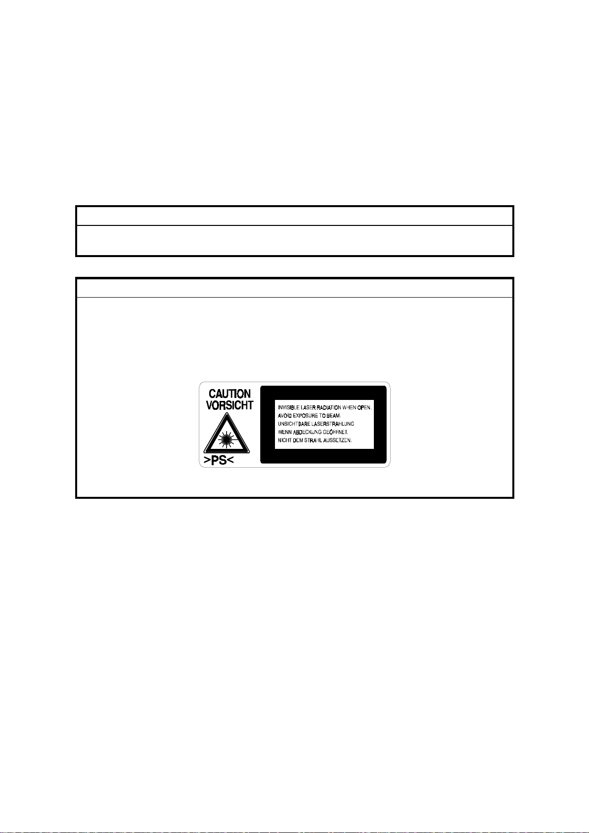
WARNING FOR LASER UNIT
WARNING: Turn off the main switch before attempting any of the
procedures in the Laser Unit section. Laser beams can
seriously damage your eyes.
CAUTION MARKING:
laser-4.WMF
ii
Page 29
OVERALL INFORMATION
PAPER TRAY UNIT A860
DETAILED DESCRIPTIONS
LARGE CAPACITY TRAY A862
INSTALLATION
BY-PASS UNIT A899
SERVICE TABLES
INTERCHANGE UNIT B300
FINISHER A681
SCANNER KIT A844
FAX UNIT A895
ISDN UNIT A895
TAB
POSITION 1
TAB
POSITION 2
TAB
POSITION 3
TAB
POSITION 4
PREVENTIVE MAINTENANCE
DUPLEX A896
PRINTER CONTROLLER B306
REPLACEMENT AND ADJUSTMENT
1 BIN TRAY UNIT A898
NETWORK INTERFACE BOARD B307
TROUBLESHOOTING
BRIDGE UNIT A897
AUTO RECIRCULATING DOCUMENT FEEDER A858
SHIFT TRAY UNIT B313
TAB
POSITION 5
TAB
POSITION 6
TAB
POSITION 7
TAB
POSITION 8
Page 30

Page 31

OVERALL MACHINE INFORMATION
Page 32

Page 33

1. OVERALL MACHINE INFORMATION
1.1 SPECIFICATIONS
Configuration: Desktop
Copy Process: Dry electrostatic transfer system
Originals: Sheet/Book
Original Size: Maximum A3/11" x 17"
Copy Paper Size: Maximum
A3/11" x 17"
Minimum
A5/8
Custom sizes
2nd paper tray
Width: 100 ~ 297 mm (3.9" ~ 11.5")
Length: 148 ~ 432 mm (5.8" ~ 17.0")
By-pass tray (Option):
Width: 90 ~ 305 mm (3.5" ~ 12.0")
Length: 148 ~ 1,260 mm (5.8" ~ 49.6")
1/2
" x 5
" lengthwise
1/2
SPECIFICATIONS
Overall
Information
Copy Paper Weight: Paper Tray:
60 ~ 105 g/m2, 16 ~ 28 lb (1st paper tray)
60 ~ 157 g/m2, 16 ~ 43 lb (2nd paper tray)
By-pass (Option):
60 ~ 157 g/m2, 16 ~ 42 lb
Reproduction Ratios: 5 Enlargement and 7 Reduction
A4/A3 Version LT/DLT Version
400%
200%
Enlargement
Full Size 100% 100%
Reduction
141%
122%
115%
93%
87%
82%
71%
65%
50%
25%
400%
200%
155%
129%
121%
93%
85%
78%
73%
65%
50%
25%
SM 1-1 A265/A267
Page 34

SPECIFICATIONS
Zoom: 25% to 400% in 1% steps (Platen mode)
50% to 200% in 1% steps (ADF mode)
Power Source: 120 V, 60 Hz:
More than 12 A (for North America)
220 ~ 240 V, 50/60 Hz
More than 6 A (for Europe/Asia)
110 V, 50/60 Hz
More than 13 A (for Taiwan)
Power Consumption:
Mainframe Only Full System
120 V 220 ~ 240 V 120 V 220 ~ 240 V
Maximum
Copying
Warm-up
Stand-by
Low Power Level 1 Approx. 80 Wh Approx. 85 Wh Approx. 80 Wh Approx. 85 Wh
Low Power Level 2 Approx. 50 Wh Approx. 50 Wh Approx. 50 Wh Approx. 50 Wh
Auto Off 10 W -- 10 W --
Less than
1.44 kW
Approx.
500 Wh
Approx.
1.0 kW
Approx.
120 Wh
Less than
1.44 kW
Approx.
500 Wh
Approx.
1.0 kW
Approx.
120 Wh
Less than
1.44 kW
Approx.
500 Wh
Approx.
1.0 kW
Approx.
130 Wh
Less than
1.44 kW
Approx.
500 Wh
Approx.
1.0 kW
Approx.
130 Wh
NOTE:
1) Full system: Mainframe + ADF + 1-bin Sorter + Paper Tray Unit +
Duplex Unit + Bridge Unit + Finisher
2) Without the optional heaters, fax unit, and printer controller
Noise Emission (Sound Power Level):
Stand-by (Mainframe only): US/Asia Model: 40 dB(A)
Europe Model: 40 dB(A)
Operating (Mainframe only): US/Asia Model: 64 dB(A)
Europe Model: 64 dB(A)
Operating (Full System): 67.5 dB(A)
NOTE:
1) The above measurements were made in accordance with ISO 7779.
2) Full System: Mainframe + ADF + 1-bin Sorter + Paper Tray Unit +
Duplex Unit + Bridge Unit + Finisher
A265/A267 1-2 SM
Page 35

SPECIFICATIONS
Dimensions (W x D x H): 550 x 580 x 709 mm (21.7" x 22.8" x 28.0")
NOTE:
Measurement Conditions
1) With the paper tray unit or LCT
2) Without the ADF
Weight: Less than 62 kg (136.7 lb)
Copying Speed (copies/minute):
Overall
Information
Russian-C1A
Non-memory copy mode 22 12
Memory copy mode 22 13
Russian-C1B
Non-memory copy mode 22 12
Memory copy mode 27 15
NOTE:
Measurement Conditions
A4 sideways/
11" x 8
A4 sideways/
11" x 8
1/2
1/2
"
"
A3/11" x 17"
A3/11" x 17"
1) Not APS mode
2) A4/LT copying
3) Full size
Warm-up Time: Less than 45 seconds (20°C, 68°F)
First Copy Time: Less than 4.9 s (A4), less than 5.0 s (LT)
NOTE:
Measurement Conditions
1) When the polygonal mirror motor is spinning.
2) From the 1st paper tray
3) Not APS mode
4) Full size
Copy Number Input: Ten-key pad, 1 to 99 (count up or count down)
Manual Image Density: 7 steps
SM 1-3 A265/A267
Page 36

SPECIFICATIONS
Paper Tray Capacity: Paper Tray:
500 sheets x 2
(Special paper in the 2nd paper tray: 50 sheets)
Paper Tray Unit (Option):
500 sheets x 2
LCT (Option):
1000 sheets x 2
By-pass Tray (Option):
100 sheets (A4, B5, A5, B6, 8
10 sheets (A3, B4, 11" x 17", 8
" x 11", 5
1/2
" x 13")
1/2
1/2
" x 8
1/2
")
1 sheet (non-standard sizes)
NOTE:
Copy paper weight: 80g/m2 (20 lb)
Toner Replenishment: Cartridge exchange (360 g/cartridge)
Toner Yield: 10 k copies (A4 sideways, 6% full black, 1 to 1 copying,
ADS mode)
Copy Tray Capacity: Copy Tray: 500 sheets (without 1-bin tray)
250 sheets (with 1-bin tray)
Memory Capacity: Standard 20 MB, Optional memory 48 MB
A265/A267 1-4 SM
Page 37

1.2 MACHINE CONFIGURATION
1.2.1 SYSTEM COMPONENTS
2
1
12
MACHINE CONFIGURATION
3
4
Overall
Information
11
10
5
6
7
A265V501.WMF
89
SM 1-5 A265/A267
Page 38

MACHINE CONFIGURATION
Version Item Machine Code No.
Copier
Copier A265 1
Copier A267 1
ARDF (Optional) A858 3
Platen Cover (Optional) A893 2
Paper Tray Unit - 2 tray (Optional)
LCT (Optional) A862 8
1-bin Tray (Optional) A898 4
Shift Tray (Optional) B313 12
Duplex Unit (Optional) A896 6
By-pass Tray (Optional) A899 7
Interchange Unit (Optional) B300 5
Bridge Unit (Optional) A897 11
1000-sheet Finisher (Optional) A681 10
Copier Feature Expander - Memory
48 MB (Optional)
Key Counter Bracket
Fax
Fax Controller (Optional)
G3 Interface Unit (Optional) A895-11, -12
Handset (Optional) H160
ISDN (Optional) A895-21, -22
PC Fax Expander (Optional) A894
Fax Function Expander (Optional) A892
Printer
Printer Controller (Optional) B306
PostScript Kit (Optional) B308
HDD (Optional) G690
NIB (Optional) B307
Memory 32 or 64 MB (Optional) G688
Scanner Scanner Controller (Optional) A844
A860-11, -21,
-56
A887
A895-01, -02,
-03
9
A265/A267 1-6 SM
Page 39

Rev. 03/2000
1.2.2 INSTALLABLE OPTION TABLE
Copier options
MACHINE CONFIGURATION
No. Option A265/A267 Note
1 ARDF (Optional)
2 Platen Cover (Optional)
3 Paper Tray Unit - 2 tray (Optional)
4 LCT (Optional)
5 1-bin Tray (Optional)
6 Shift Tray (Optional)
7 Duplex Unit (Optional)
8 By-pass Tray (Optional)
9 Interchange Unit (Optional)
10 Bridge Unit (Optional)
⇒
11 1000-sheet Finisher (Optional)
12 Memory 48 MB (Optional)
13 Key Counter Bracket
= Available
!
Fax and printer options
∆
= Requires another option
!
!
!
!
∆
!
∆
!
!
∆
∆
!
!
Overall
Information
Install either no. 1 or 2
Install either no. 1 or 2
Install either no. 3 or 4
Install either no. 3 or 4
Requires no.9
Install either no. 6 or 10
Requires no.9
No. 10 requires no.11
Install either no. 6 or 10
Requires no.10 and
either no.3 or 4
All options for the fax and printer units are available when these units have been
installed.
Scanner option
When the scanner option is installed, the printer option must be installed.
SM 1-7 A265/A267
Page 40

PAPER PATH
1.3 PAPER PATH
8
1
2
3
4
7
5
6
1. Optional ADF
2. Optional 1-bin Tray
3. Optional Interchange Unit
4. Optional Duplex Unit
5. Optional By-pass Feed Tray
6. Optional Paper Tray Unit
7. Optional 1000-sheet Finisher
8. Optional Bridge Unit
A267V102.WMF
A265/A267 1-8 SM
Page 41

MECHANICAL COMPONENT LAYOUT
1.4 MECHANICAL COMPONENT LAYOUT
1 2 3 4 5 6 7
29
28
Overall
Information
8
9
27
26
25
24
10
11
12
13
14
15
16
17
18
19
20
21
A265V100.WMF
2223
SM 1-9 A265/A267
Page 42

MECHANICAL COMPONENT LAYOUT
1. 2nd scanner
2. Original width sensor
3. Exposure lamp
4. 1st scanner
5. Original length sensor
6. Lens
7. Scanner motor
8. SBU board
9. Exit roller
10. Fusing hot roller
11. Fusing pressure roller
12. Cleaning unit
13. OPC drum
14. Transfer roller
15. Development roller
16. ID sensor
17. Registration roller
18. Friction pad
19. Paper feed roller
20. Paper size sensor
21. Special paper sensor
22. Bottom plate
23. Tray heater
24. Polygon mirror motor
25. Laser unit
26. Toner supply bottle holder
27. Drum charge roller
28. Anti-condensation heater
29. Scanner home position sensor
A265/A267 1-10 SM
Page 43

ELECTRICAL COMPONENT DESCRIPTIONS
1.5 ELECTRICAL COMPONENT DESCRIPTIONS
Refer to the electrical component layout on the reverse side of the point-to-point
diagram for the location of the components.
Symbol Name Function
Motors
M1 Scanner Drives the 1st and 2nd scanners.
M2 Polygonal Mirror Turns the polygonal mirror.
M3 Main Drives the main unit components.
M4 Exhaust Fan Removes heat from around the fusing unit.
M5 Upper Paper Lift Raises the bottom plate in the 1st paper tray.
M6 Lower Paper Lift Raises the bottom plate in the 2nd paper tray.
M7
Magnetic Clutches
MC1 Upper Paper Feed Starts paper feed from the 1st paper tray.
MC2 Lower Paper Feed Starts paper feed from the 2nd paper tray.
MC3 Upper Relay Drives the upper relay rollers.
MC4 Lower Relay Drives the lower relay rollers.
MC4 Registration Drives the registration rollers.
Toner Supply Rotates the toner bottle to supply toner to the
development unit.
Overall
Information
Switches
SW1 Main
SW2 Right Upper Cover
SW3 Right Cover
SW4 Right Lower Cover
SW5 Upper Paper Size
SW6 Lower Paper Size
SW7 Special Paper
SW8 New PCU Detect Detects when a new PCU is installed.
SW9 Front Cover Safety
SW10 Operation
Provides power to the machine. If this is off, there
is no power supplied to the machine.
Detects whether the right upper cover is open or
not.
Cuts the +5VLD and +24V dc power line and
detects whether the right cover is open or not.
Detects whether the right lower cover is open or
not.
Determines what size of paper is in the upper
paper tray.
Determines what size of paper is in the lower
paper tray.
Determines whether there is special paper in the
lower paper tray.
Cuts the +5VLD and +24V dc power line and
detects whether the front cover is open or not.
Provides power for machine operation. The
machine still has power if this switch is off.
SM 1-11 A265/A267
Page 44

ELECTRICAL COMPONENT DESCRIPTIONS
Symbol Name Function
Sensors
S1 Scanner HP
Informs the CPU when the 1st and 2nd scanners
are at home position.
Informs the CPU that the platen cover is in the up
S2 Platen Cover
or down position (related to the APS/ARE
functions).
S2 Original Width
S4 Original Length 1
S5 Original Length 2
S6 Toner Density (TD)
S7 1st Paper End
S8 2nd Paper End
S9 Image Density (ID)
Detects original width. This is one of the APS
(Auto Paper Select) sensors.
Detects original length. This is one of the APS
(Auto Paper Select) sensors.
Detects original length. This is one of the APS
(Auto Paper Select) sensors.
Detects the amount of toner inside the
development unit.
Informs the CPU when the 1st paper tray runs out
of paper.
Informs the CPU when the 2nd paper tray runs out
of paper.
Detects the density of various patterns and the
reflectivity of the drum for process control.
S10 Paper Overflow Detects paper overflow in the built-in copy tray.
S11 Paper Exit Detects misfeeds.
S12 Upper Relay Detects misfeeds.
S13 Lower Relay Detects misfeeds.
S14 Registration
S15 1st Paper Lift
S16 2nd Paper Lift
Detects misfeeds and controls registration clutch
off-on timing.
Detects when the paper in the 1st paper tray is at
the feed height.
Detects when the paper in the 2nd paper tray is at
the feed height.
S17 1st Paper Height – 1 Detects the amount of paper in the 1st paper tray.
S18 1st Paper Height – 2 Detects the amount of paper in the 1st paper tray.
S19 2nd Paper Height – 1 Detects the amount of paper in the 2nd paper tray.
S20 2nd Paper Height – 2 Detects the amount of paper in the 2nd paper tray.
PCBs
PCB1
BICU (Base Engine and
Image Control Unit)
PCB2 PSU (Power Supply Unit)
PCB3 IOB (Input/Output Board)
PCB4 SBU (Sensor Board Unit)
Controls all base engine functions both directly
and through other control boards.
Provides dc power to the system and ac power to
the fusing lamp and heaters.
Controls the fusing lamp and the mechanical parts
of the machine.
Contains the CCD, and outputs a video signal to
the BICU board.
PCB5 Lamp Stabilizer Stabilizes the power to the exposure lamp.
PCB6 LDD (Laser Diode Driver) Controls the laser diode.
PCB7 Operation Panel Controls the operation panel.
A265/A267 1-12 SM
Page 45

ELECTRICAL COMPONENT DESCRIPTIONS
Symbol Name Function
PCB8 High Voltage Supply
PCB9 Memory (Option)
Supplies high voltage to the drum charge roller,
development roller, and transfer roller.
Expands the memory capacity for the copier
features.
Lamps
L1 Exposure Lamp
Applies high intensity light to the original for
exposure.
L2 Fusing Lamp Heats the hot roller.
L3
Quenching Lamp Neutralizes any charge remaining on the drum
surface after cleaning.
Heaters
H1
Anti-condensation
(Option)
Turns on when the main power switch is off to
prevent moisture from forming on the optics.
Turns on when the main power switch is off to
H2 Tray (Option)
prevent moisture from forming around the paper
trays.
Overall
Information
Others
TF1 Fusing Thermofuse
Opens the fusing lamp circuit if the fusing unit
overheats.
TH1 Fusing Thermistor Detects the temperature of the hot roller.
LSD 1
Laser Synchronization
Detector
Detects the laser beam at the start of the main
scan.
CO1 Mechanical Counter Keeps track of the total number of prints made.
Used for control of authorized use. If this feature is
CO2 Key Counter (Option)
enabled for copying, copying will be impossible
until it is installed.
SM 1-13 A265/A267
Page 46

DRIVE LAYOUT
1.6 DRIVE LAYOUT
Scanner
2
1
A267V301.WMF
Fusing
3
4
5
PCU/Transfer Drive
1. Scanner Drive Motor
2. Main Motor
3. Registration Clutch
4. Upper Paper Feed Clutch
5. Upper Transport Clutch
6. Lower Paper Feed Clutch
7. Lower Transport Clutch
6
7
A267V302.WMF
A265/A267 1-14 SM
Page 47

1.7 COPY PROCESS
1.7.1 OVERVIEW
9
2
COPY PROCESS
Overall
Information
1
A267V401.WMF
7
8
6
3
5
4
A267V101.WMF
1. EXPOSURE
A xenon lamp exposes the original. Light reflected from the original passes to
the CCD, where it is converted into an analog data signal. This data is
converted to a digital signal, processed and stored in the memory. At the time
of printing, the data is retrieved and sent to the laser diode. For multi-copy runs,
the original is scanned once only and stored to the memory.
2. DRUM CHARGE
In the dark, the charge roller gives a negative charge to the organic photoconductive (OPC) drum. The charge remains on the surface of the drum
because the OPC layer has a high electrical resistance in the dark.
SM 1-15 A265/A267
Page 48

COPY PROCESS
3. LASER EXPOSURE
The processed data scanned from the original is retrieved from the memory
and transferred to the drum by a laser beam, which forms an electrical latent
image on the drum surface. The amount of charge remaining as a latent image
on the drum depends on the laser beam intensity, which is controlled by the
BICU board.
4. DEVELOPMENT
The magnetic developer brush on the development rollers comes in contact
with the latent image on the drum surface. Toner particles are electrostatically
attached to the areas of the drum surface where the laser reduced the negative
charge on the drum.
5. ID SENSOR
The laser forms a sensor pattern on the drum surface. The ID sensor measures
the reflectivity of the pattern. The output signal is one of the factors used for
toner supply control. Also, the ID sensor measures the reflectivity of the drum
surface. The output signal is used for charge roller voltage control.
6. IMAGE TRANSFER
Paper is fed to the area between the drum surface and the transfer roller at the
proper time for aligning the copy paper and the developed image on the drum
surface. Then, the transfer roller applies a high positive charge to the reverse
side of the paper. This positive charge pulls the toner particles from the drum
surface onto the paper. At the same time, the paper is electrostatically attracted
to the transfer roller.
7. PAPER SEPARATION
Paper separates from the drum as a result of the electrostatic attraction
between the paper and the transfer roller. The discharge plate helps separate
the paper from the drum.
8. CLEANING
The cleaning blade removes any toner remaining on the drum surface after the
image transfers to the paper.
9. QUENCHING
The light from the quenching lamp electrically neutralizes the charge on the
drum surface.
A265/A267 1-16 SM
Page 49

1.8 BOARD STRUCTURE
1.8.1 OVERVIEW
BOARD STRUCTURE
Overall
Information
: Standard
: Option
Paper
Tray Unit/
LCT
By-pass Duplex 1-Bin Tray
ARDF
APS
Sensors
Xenon Lamp
Lamp
Stabilizer
Bridge
Unit
Printer
Scanner
Options
Scanner
Motor
IOB
Finisher Sensors
Mother
Board
Fax Unit
SBU
Operation
Panel
Clutches/
Solenoids
Motors
BICU
Voltage
High
P.P
Ther-
mistor
LSD
LD Unit
Polygon
Motor
EMB
PSU
Fusing Lamp
A267V500.WMF
SM 1-17 A265/A267
Page 50

BOARD STRUCTURE
1.8.2 DESCRIPTION
1. BICU (Base Engine and Image Control Unit)
The main board controls the following functions:
•
Engine sequence
•
Scanner, laser printer engine
•
Timing control for peripherals
•
Image processing, video control
•
Operation control
•
Various application boards (fax, printer, scanner)
•
Machine control, system control
2. IOB (I/O Board)
The IOB handles the following functions:
•
Drive control for the sensors, motors, and solenoids of the printer and
scanner
•
High voltage control board control
•
Serial interfaces with peripherals
•
Fusing control
3. SBU (Sensor Board Unit)
The SBU deals with the analog signals from the CCD and converts them into digital
signals.
4. Mother Board (Option)
This board interfaces the BICU with the printer controller and/or the scanner
controller. The mother board is part of the expansion box option.
A265/A267 1-18 SM
Page 51

DETAILED DESCRIPTIONS
Page 52

Page 53

2. DETAILED SECTION DESCRIPTIONS
2.1 SCANNING
2.1.1 OVERVIEW
SCANNING
[E]
[G]
The original is illuminated by the exposure lamp (a xenon lamp in this model) [A].
The image is reflected onto a CCD (charge coupled device) [B] via the 1st, 2nd, 3rd
mirrors, and lens [C].
The 1st scanner [D] consists of the exposure lamp, a reflector [E], and the 1st
mirror [F].
A lamp stabilizer energizes the exposure lamp. The light reflected by the reflector is
of almost equal intensity, to reduce shadows on pasted originals.
[F]
[A]
[D]
[C]
A265D506.WMF
[B]
Detailed
Descriptions
An optics anti-condensation heater [G] is available as an option. It can be installed
on the left side of the scanner. It turns on whenever the power cord is plugged in
and the main power switch is off.
SM 2-1 A265/A267
Page 54

SCANNING
2.1.2 SCANNER DRIVE
[B]
[H]
[G]
[A]
[E]
[D]
[G]
[C]
[F]
A267D002.WMF
[E]
A stepper motor drives the scanner. The 1st and 2nd scanners [A,B] are driven by
the scanner drive motor [C] through the timing belt [D], scanner drive pulley [E],
scanner drive shaft [F], and two scanner wires [G].
- Book mode -
The scanner drive board controls and operates the scanner drive motor. In full size
mode, the 1st scanner speed is 122 mm/s during scanning. The 2nd scanner
speed is half that of the 1st scanner.
In reduction or enlargement mode, the scanning speed depends on the
magnification ratio. The returning speed is always the same, whether in full size or
magnification mode. The image length change in the sub scan direction is done by
changing the scanner drive motor speed, and in the main scan direction it is done
by image processing on the BICU board.
Magnification in the sub-scan direction can be adjusted by changing the scanner
drive motor speed using SP4-101. Magnification in the main scan direction can be
adjusted using SP4-008.
- ADF mode -
The scanners are always kept at their home position (the scanner H.P sensor [H]
detects the 1st scanner) to scan the original. The ADF motor feeds the original
through the ADF. In reduction/enlargement mode, the image length change in the
sub-scan direction is done by changing the ADF motor speed. Magnification in the
main scan direction is done in the BICU board, like for book mode.
Magnification in the sub-scan direction can be adjusted by changing the ADF motor
speed using SP6-007. In the main scan direction, it can be adjusted with SP4-008,
like for book mode.
A265/A267 2-2 SM
Page 55

2.1.3 ORIGINAL SIZE DETECTION IN PLATEN MODE
[D]
[A]
SCANNING
Detailed
Descriptions
[B]
[C]
A265D504.WMF
In the optics cavity for original size detection, there are four reflective sensors in
the 115V machines ([A] and [B]), and six reflective sensors in the 230V machines.
The original width sensors [A] detect the original width, and the original length
sensors [B] and [C] detect the original length. These are the APS (Auto Paper
Select) sensors. Each APS sensor is a reflective photosensor.
While the main switch is on, these sensors are active and the original size data is
always sent to the CPU. However, the CPU checks the data only when the platen
cover sensor [D] is activated. This is when the platen is positioned about 15 cm
above the exposure glass, for example while it is being closed. The CPU can
recognize the original size from the combination of on/off signals from the APS
sensors.
If the copy is made with the platen fully open, the CPU decides the original size
from the sensor outputs when the Start key is pressed.
SM 2-3 A265/A267
Page 56

SCANNING
L1L2
L3L4
W2
W1
A265D505.WMF
Original Size Length Sensor Width Sensor
A4/A3
version
A3 11” x 17” OOOOOO
B4 10” x 14” OOOOOX
Foolscap 8.5” x 13” O O O X X X
A4-L 8.5” x 11”OOXXXX
B5-L OXXXXX
A4-S 11” x 8.5”XXXXOO
B5-S XXXXOX
A5-L, A5-S XXXXXX
LT/DLT
version
L4 L3 L2 L1 W2 W1
NOTE:
1) L: Lengthwise, S: Sideways, O: High (paper present), X: Low
2) The length sensors L3 and L4 are used only for 230V machines.
For other combinations, "CANNOT DETECT ORIG. SIZE" will be indicated on the
operation panel display (if SP 4-303 is kept at the default setting).
The above table shows the outputs of the sensors for each original size. This
original size detection method eliminates the necessity for a pre-scan and
increases the machine's productivity.
However, if the by-pass feeder is used, note that the machine assumes that the
copy paper is lengthwise. For example, if A4 sideways paper is placed on the bypass tray, the machine assumes it is A3 paper and scans the full A3 area for the
first copy of each page of the original, disregarding the original size sensors.
However, for each page, the data signal to the laser diode is stopped to match the
copy paper length detected by the registration sensor.
Original size detection using the ADF is described in the manual for the ADF.
A265/A267 2-4 SM
Page 57

2.2 IMAGE PROCESSING
2.2.1 OVERVIEW
IMAGE PROCESSING
SBU
CCD
Memory
Control
IC
BICU
EMB
MB
Fax Controller
Printer Controller
Scanner Controller
A265D500.WMF
Drum
LDD
LD
Driver
LD
Controller
(VCU)
FCI
IPU
The CCD generates an analog video signal. The SBU (Sensor Board Unit)
converts the analog signal to an 8-bit digital signal, then it sends the digital signal
to the BICU (Base-engine and Image Control Unit) board.
The BICU board and LDD Board can be divided into three image processing
blocks; the IPU (Image Processing Unit), FCI (Fine Character Image), and LD
controller (VCU).
•
IPU: Auto shading, filtering, magnification, γ correction, and gradation processing
•
LD controller: LD print timing control and laser power PWM control
•
FCI (inside the LD controller): Smoothing (binary picture processing mode only)
Detailed
Descriptions
The EMB board is the copier feature expander option, which provides extra
memory for the copier features.
SM 2-5 A265/A267
Page 58

IMAGE PROCESSING
2.2.2 SBU (SENSOR BOARD UNIT)
SBU
O
Analog
Processing IC1
A/D 1
GA
8 bit data
BICU
IPU
CCD
E
Analog
Processing IC2
A/D 2
8 bit data
A265D501.WMF
The CCD converts the light reflected from the original into an analog signal. The
CCD line has 7,450 pixels and the resolution is 600 dpi (23.6 lines/mm).
The CCD has two output lines, for odd and even pixels, to the analog processing
IC. The analog processing IC performs the following operations on the signals from
the CCD:
1. Z/C (Zero Clamp):
Adjusts the black level reference for even pixels to match the odd pixels.
2. Signal Amplification:
The analog signal is amplified by operational amplifiers in the AGC circuit. The
maximum gains of the operational amplifiers are controlled by the CPU on the
BICU board.
After the above processing, the analog signals are converted to 8-bit signals by the
A/D converter. This will give a value for each pixel on a scale of 256 grades. Then,
the digitized image data is sent to the BICU board.
A265/A267 2-6 SM
Page 59

2.2.3 AUTO IMAGE DENSITY
IMAGE PROCESSING
0.5mm
Sub scan direction
[A]
20mm
80mm
A265D502.WMF
In the SBU
ADS prevents the background of an original from appearing on copies.
The copier scans the auto image density detection area [A] as shown in the
diagram. This corresponds to a few mm at one end of the main scan line. As the
scanner scans down the page, the IPU on the BICU detects the peak white level
for each scan line. The IPU determines the reference value for the A/D conversion
for a particular scan line using the peak white level for that scan line. Then, the IPU
sends the reference value data to the reference controller on the SBU.
Detailed
Descriptions
When an original with a gray background is scanned, the density of the gray area
is the peak white level density. Therefore, the original background will not appear
on copies. Because peak level data is taken for each scan line, ADS corrects for
any changes in background density down the page.
As with previous digital copiers, the user can select manual image density when
selecting auto image density mode, and the machine will use both settings when
processing the original.
In the IPU
After the SBU process, the IPU board removes background noise resulting from
the SBU-BICU wiring by adjusting the white level.
“Service Mode” Original Types
If the user selects a “Service Mode” original type with the user tools, these two
ADS process can be either enabled or disabled (SP4-936, SP4-937), and the
amount of white level change for the IPU ADS process can be adjusted (SP4-938).
SM 2-7 A265/A267
Page 60

IMAGE PROCESSING
2.2.4 IPU (IMAGE PROCESSING UNIT)
Overview
BICU
Fax Controller
Scanner
Controller
Printer Controller
A265D503.WMF
LD
SBU
LDD
FCI
VCU
IPU
Memory
Controller
DRAM
MB
EMB
The image data from the SBU goes to the IPU (Image Processing Unit) IC on the
BICU board, which carries out the following processes on the image data.
1. Auto shading
2. Scanner gamma correction
3. Filtering (MTF and smoothing)
4. Magnification
5. ID gamma correction
6. Grayscale processing
7. Binary picture processing
8. Error diffusion
9. Dithering
10. Video path control
11. Test pattern generation
The image data then goes to the LD driver (LDD).
A265/A267 2-8 SM
Page 61

IMAGE PROCESSING
Image Processing Modes
The user can select text, text/photo, and photo original types, as usual. However,
each of these original types has a range of different choices (such as ”sharp text”,
“glossy photo”, etc). these are listed in the table on the following page.
•
Notice that there is a “Service Mode” for each of the text, text/photo, and
photo original modes. This is a customizable mode, with a range of SP
modes that can be adjusted to meet user requirements that are not covered
by the other original modes.
In addition, there are two main image processing modes: grayscale processing
mode (called “Enhanced Mode” on the display) and binary picture processing mode
(called “Normal Mode” on the display). Either of these can be selected for each
original type.
The user can select the modes that best suit their original with the following user
tools:
•
Greyscale/Binary Picture: UT mode - 2. Copier – 1. General Features – 08.
Image Mode Select
•
Original Type: UT mode - 2. Copier – 1. General Features – 09. Image Mode
Adjustment (select text, text/photo, or photo at the operation panel, then
select the sub-type with this UT mode)
For details of the SP modes that can be used to adjust the image quality for all the
original modes, see the “SP Modes for Each Image Processing Step” section.
Detailed
Descriptions
SM 2-9 A265/A267
Page 62

IMAGE PROCESSING
Normal Mode
(Binary Picture
Processing)
Enhanced Mode
(Grayscale
Processing)
Original
Type
Text
Text/Photo
Photo
Text
Text/Photo
Photo
Mode Targeted Original Type
Normal Normal text originals
Sharp Newspaper, originals through which
the rear side is visible
Service mode Default: Printouts from dot matrix
printers
Photo priority
Text/photo originals which contain
mainly photo areas
Text priority Text/photo originals which contain
mainly text areas
Service mode Default: Colored originals (with blue
or green text or background)
Coarse print
Coarse-grained printed originals,
with no text
Press print Fine-grained printed originals, with
no text
Glossy photo Glossy photos
Service mode Default: Fine-grained printed
originals, with no text.
Pale Originals with low contrast text
(such as written by a pencil)
Normal Normal text originals
Generation Copied originals
Service mode
Default: Printouts from dot matrix
printers
Text priority
Text/photo originals which contain
mainly text areas
Normal Text/photo originals
Photo priority Text/photo originals which contain
mainly photo areas
Service mode Default: Colored originals (with blue
or green text or background)
Press print
Fine-grained printed originals, with
no text.
Normal Normal photos
Glossy Photo Glossy photos
Service mode Default: Normal photos
A265/A267 2-10 SM
Page 63

IMAGE PROCESSING
Image Processing Path
Overview
This diagram shows the various stages of the image process and where they are
done.
Image Correction
• ADS
SBU
8
Image Correction
• ADS
• Auto Shading
• White/Black Line Erase
Correction
• Scanner Gamma Correction
• Small Smoothing Filter
8
Magnification (Main Scan)
8
Filtering
• MTF
• Smoothing
• Independent Dot Erase
8
ID Gamma Correction
8
Gradation
• Error Diffusion
• Dithering
• Binary Picture Processing
• Grayscale Processing
2
1
Detailed
Descriptions
Others
• Independent Dot Erase
• Line Width Correction
Optional
Printer
Controller
• Printer Gamma Correction
Video Path Control
1
21
LD Unit
Binary Picture Processing
Grayscale Processing
2
1
IPU
BICU
1
8
1
Optional
Fax Unit
Optional
Scanner
Controller
A265D509.WMF
SM 2-11 A265/A267
Page 64

IMAGE PROCESSING
SP Modes for Each Image Processing Step
The following tables show which SP modes are used for each step in image
processing mode.
There are also some SP modes specifically for use with the positive/negative
feature:
•
4-403: Can be used to disable greyscale processing for this feature
•
4-947: MTF
•
4-948: Dynamic threshold maximum and minimum limits
Text Mode, Binary Picture Processing
Text Mode
Normal Sharp Service Mode
ADS (SBU) As selected at the operation panel
ADS (IPU) As selected at the operation panel
Shading Correction Enabled Enabled
White Line Correction
Black Line Correction
Scanner γ Correction
Small Smoothing Filter Not used Normal
Main Scan
Magnification
Mirroring Enabled only in the ADF mode
MTF/Smoothing Filter MTF (Medium) MTF (Weak)
Independent Dot Erase
ID γ Correction
Gradation Error diffusion Binary picture processing
Threshold Dynamic Dynamic
Independent Dot Erase
(after image process)
Line Width Correction Disabled
Enabled (DF only)
4-943
4-944 (Enable/disable)
Text / normal Text / sharp Text / sharp
Enabled
4-942
Enabled (DF only)
4-943
AE linear
Enabled
Weak
None
As on the op panel
4-936-4
As on the op panel
4-937-4, 4-938-4
Enabled
4-918-4
Strong (DF only)
4-919-4
Linear
4-928-4
Normal
4-921-3
MTF (Weak)
4-915-23~34
4-916-23~34
Strong
4-917-3
4-940-4
Dynamic
4-922-1
4-923 ~ 4-926
4-931 ~ 4-934
None
4-939
Thinner Lines
(medium)
4-935-4
A265/A267 2-12 SM
Page 65

IMAGE PROCESSING
Text Mode, Grayscale Processing
Text Mode
Pale Normal Generation
ADS (SBU) As selected at the operation panel
ADS (IPU) As selected at the operation panel
Shading Correction Enabled Enabled
White Line Correction
Enabled
4-942
Black Line Correction Enabled (DF only) 4-943
Scanner γ Correction
AE linear
Small Smoothing Filter Normal
Main Scan
Magnification
Enabled
Mirroring Enabled only in the ADF mode
MTF/Smoothing Filter MTF (Medium)
Independent Dot Erase
ID γ Correction
4-944 (Enable/disable)
Weak
Text
Gradation Error diffusion
Threshold Constant
Independent Dot Erase
(after image process)
Line Width Correction
Thick
(Medium)
None
Disabled
Thin
(Medium)
Service
Mode
As op panel
4-936-1
As op panel
4-937-1
4-938-1
Enabled
4-918-1
Strong (DF
only) 4-919-1
Linear
4-928-1
Normal
4-921-1
MTF
(Medium)
4-915-1~10
4-916-1~10
Strong
4-917-1
Text
4-940-1
Constant
4-929-1
None
4-939
Disabled
4-935-1
Detailed
Descriptions
SM 2-13 A265/A267
Page 66

IMAGE PROCESSING
Text/Photo Mode, Binary Picture Processing
Text/Photo Mode
Photo Priority Text Priority Service Mode
ADS (SBU) As selected at the operation panel
ADS (IPU) As selected at the operation panel
Shading Correction Enabled Enabled
White Line Correction
Black Line Correction
Scanner γ Correction
Small Smoothing Filter Not used Normal
Main Scan
Magnification
Mirroring Enabled only in the ADF mode
MTF/Smoothing Filter MTF (Weak) MTF (Weakest)
Independent Dot Erase
ID γ Correction
Gradation Error diffusion
Threshold Constant
Independent Dot Erase
(after image process)
Line Width Correction Disabled
Enabled (DF only)
4-943
4-944 (Enable/disable)
Photo priority Text Priority
Enabled
4-942
Enabled (DF only)
4-943
AE linear
Enabled
Weak
None
As on the op panel
4-936-5
As on the op panel
4-937-5, 4-938-5
Enabled
4-918-5
Strong (DF only)
4-919-5
As op panel
4-928-5
Normal
4-921-4
MTF (Weakest)
4-915-35~48
4-916-35~48
Weak
4-917-4
Text Priority
4-940-5
Constant
4-922-2
4-929-4
Thicker Lines
(strong)
4-935-5
A265/A267 2-14 SM
Page 67

IMAGE PROCESSING
Text/Photo Mode, Grayscale Processing
Text/Photo Mode
Text Priority Normal
Photo
Priority
ADS (SBU) As selected at the operation panel
ADS (IPU) As selected at the operation panel
Shading Correction Enabled Enabled
White Line Correction
Enabled
4-942
Black Line Correction Enabled (DF only) 4-943
Scanner γ Correction
AE linear
Small Smoothing Filter Normal
Main Scan
Magnification
Enabled
Mirroring Enabled only in the ADF mode
MTF/Smoothing Filter MTF (Weak) MTF (Weakest)
Independent Dot Erase
ID γ Correction
4-944 (Enable/disable)
Text priority Photo priority
Weak
Gradation Error diffusion
Threshold Constant
Independent Dot Erase
(after image process)
None
Line Width Correction Disabled
Service
Mode
As op panel
4-936-2
As op panel
4-937-2
4-938-2
Enabled
4-918-2
Strong (DF
only) 4-919-2
As op panel
4-928-2
Normal
4-921-2
MTF (Weak)
4-915-11~22
4-916-11~22
Weak
4-917-2
Text priority
4-940-2
Constant
4-929-2
Thick
(Strong)
4-935-2
Detailed
Descriptions
SM 2-15 A265/A267
Page 68

IMAGE PROCESSING
Photo Mode, Binary Picture Processing
Photo Mode
Coarse print Press print
ADS (SBU) As selected at the operation panel
ADS (IPU) As selected at the operation panel
Shading Correction Enabled Enabled
White Line Correction
Black Line Correction Enabled (DF only) 4-943
Scanner γ Correction
Small Smoothing Filter Not used
Main Scan
Magnification
Mirroring Enabled only in the ADF mode
MTF/Smoothing Filter Smoothing (Strong) MTF (Weak)
Independent Dot Erase None
ID γ Correction
Gradation
Threshold -- -- Constant -Independent Dot Erase
(after image process)
Line Width Correction Disabled
Coarse print Press print Glossy photo
Dither
(53 lines)
Enabled
4-942
NAE linear
Enabled
Dither
(105 lines)
None
Glossy
photo
Error
diffusion
Service
Mode
As op panel
4-936-6
As op panel
4-937-6
4-938-6
Enabled
4-918-6
Strong (DF
only) 4-919-6
As op panel
4-928-6
Smoothing
(Strong)
4-927-2
Press print
4-940-6
Dither
(105 lines)
4-929-5
Disabled
4-935-6
A265/A267 2-16 SM
Page 69

IMAGE PROCESSING
Photo Mode, Grayscale Processing
Photo Mode
Coarse print Press print
Glossy
photo
ADS (SBU) As selected at the operation panel
ADS (IPU) As selected at the operation panel
Shading Correction Enabled Enabled
White Line Correction
Enabled
4-942
Black Line Correction Enabled (DF only) 4-943
Scanner γ Correction
NAE linear
Small Smoothing Filter Not used
Main Scan
Magnification
Enabled
Mirroring Enabled only in the ADF mode
MTF/Smoothing Filter
Smoothing
(Strong)
Smoothing
(Medium)
MTF
(Weakest)
Independent Dot Erase None
ID γ Correction
Gradation
Coarse print Press print Glossy photo
Dither
(105 lines)
Dither
(143 lines)
Error
diffusion
Threshold -- -- Dynamic -Independent Dot Erase
(after image process)
None
Line Width Correction Disabled
Service
Mode
As op panel
4-936-3
As op panel
4-937-3
4-938-3
Enabled
4-918-3
Strong (DF
only) 4-919-3
As op panel
4-928-3
Smoothing
(Medium)
4-927-1
Press print
4-940-3
Dither
(143 lines)
4-929-3
Disabled
4-935-3
Detailed
Descriptions
SM 2-17 A265/A267
Page 70

IMAGE PROCESSING
Auto Shading
There are two auto shading methods. black level correction and white level
correction. Auto shading corrects errors in the signal level for each pixel.
Black Level Correction
The CPU reads the black dummy data from one end of the CCD signal (32 pixels
at the end are blacked off) and takes the average of the black dummy data. Then,
the IPU deletes the black level value from each image pixel.
White Level Correction
Before scanning the original, the machine reads a reference waveform from the
white plate. The average of the white video level for each pixel is stored as the
white shading data in the FIFO memory in the IPU chip.
The video signal information for each pixel obtained during image scanning is
corrected by the IPU chip.
Auto shading for the first original is done before the scanning.
After scanning every page, auto shading is done to prepare for the next page.
If the copy image density or the original mode is changed during copy run, the auto
shading for the next scan is done before the scanning to respond to the mode
changed.
White Line Erase Compensation
During the white level correction, if extremely low CCD output is detected in some
parts of the line, the machine assumes this is due to abnormal black lines on the
white plate. This low output is corrected using neighboring pixels. To switch off this
correction, use SP4-918 (for the original modes known as “Service Mode”) and
SP4-942 (other original modes).
Black Line Erase Compensation
In ADF mode, if extremely low CCD output is detected on the scanning line before
the leading edge of original arrives there, this is attributed to abnormal black dots
on the exposure glass. This low output is corrected using neighboring pixels. To
adjust or switch off this correction, use SP4-919 (for the original modes known as
“Service Mode”) and SP4-943 (other original modes).
A265/A267 2-18 SM
Page 71

IMAGE PROCESSING
γ)
Scanner Gamma (
γ)
Correction
γ)γ)
The CCD output is not proportional to the quantity of the light received. Scanner
gamma (γ) correction corrects the CCD output so that grayscale data is proportion
to the quantity of the light received.
The machine has four possible scanner gamma curves. The curve used by the
machine depends on the original type selected by the user (at the operation panel
and with the user tool 09: Image Mode Adjustment). If the user selects one of the
original modes known as ‘service mode’, the gamma curve can be selected with
SP4-928.
If “0” is selected with SP 4-928, the scanner gamma curve is either AE or NAE,
depending on the selected original mode (text, photo, etc.).
The four gamma (γ) correction curves and their characteristics are as follows:
•
Non Auto Exposure ID linear (NAE): Corrects the image data in proportion to the
original density.
•
Auto Exposure ID linear (AE): Removes the background from the image data to
some extent and corrects the rest of the image data in proportion to the original
density.
•
Reflection Ratio ID Linear (Linear): Uses the image data without correction.
•
Removed background (SP): Removes the background area completely and
corrects the rest of the image data in proportion to the original density.
Detailed
Descriptions
Output
Removed Background
Linear
NAE
AE
SP
Original Density
A250D550.WMF
SM 2-19 A265/A267
Page 72

IMAGE PROCESSING
Main Scan Magnification/Reduction
Changing the scanner speed enables reduction and enlargement in the sub-scan
direction. However, the IPU chip handles reduction and enlargement in the main
scan direction. The processing for main scan magnification/reduction is the same
as in the previous digital machines.
Mirroring for ADF Mode
[A]
A250D504.WMF
When making a copy using the ADF, the magnification circuit creates a mirror
image. This is because the scanning starting position in the main scan direction is
at the other end of the scan line in ADF mode (compared with platen mode). In
platen mode, the original is placed face down on the exposure glass, and the
corner at [A] is at the start of the main scan. The scanner moves down the page. In
ADF mode, the ADF feeds the leading edge of the original to the DF exposure
glass, and the opposite top corner of the original is at the main scan start position.
To create the mirror image, the IPU stores each line in a LIFO (Last In First Out)
memory.
A265/A267 2-20 SM
Page 73

IMAGE PROCESSING
Filtering
Overview
There are some software filters for enhancing the desired image qualities of the
selected original mode. These filters are the MTF filter, the smoothing filter, and
independent dot erase.
The MTF filter emphasizes sharpness and is used in Text and Text/Photo modes.
The smoothing filter is used in Photo mode, except for Glossy Photo mode. In
Glossy Photo mode, the MTF filter is used.
Independent dot erase removes unwanted dots from the image.
MTF Filter Adjustment - Text and Text/Photo Modes
When the user selects “Service Mode” for either Text or Text/Photo original type,
the MTF filter strength and coefficient can be adjusted with SP4-915 and 4-916.
It is difficult to simply explain the relationships between the filter coefficient and
filter strengths. Refer to the following charts to determine how to make the filters
weaker or stronger. A circle indicates the default setting.
Detailed
Descriptions
When the filter is stronger in the main scan direction, lines parallel to the feed
direction are emphasized. When the filter is stronger in the sub-scan direction, lines
at right angles to the feed direction are emphasized. A stronger MTF filter can
make a low ID image visible but moiré may become more visible. Moiré is reduced
using a smoothing filter specially designed for this purpose (see “Smoothing Filter
Adjustment - Text/Photo”).
SM 2-21 A265/A267
Page 74

IMAGE PROCESSING
Grayscale Processing
30
29
28
27
26
25
24
23
22
21
20
19
18
17
16
15
14
13
12
11
10
9
8
7
1323138111334453354415871515011311
533321824311245352581211111213012323
444255352555550000040050033344
444544355545550060040050033344
6
5
4
3
Weak Strong
2
1
!
!
!
!
!
!
!
!
!
!
!
Level
Main Scan: Filter Coefficient
Sub-Scan: Filter Coefficient
Main Scan: Filter Strength
Sub-Scan: Filter Strength
MTF Filter
Text (25% to 29%)
Original Type
SP4-915-1, 6 SP4-916-1, 6
Text (30% to 76%)
SP4-915-2, 7 SP4-916-2, 7
Text (77% to 154%)
SP4-915-3, 8 SP4-916-3, 8
Text (155% to 256%)
SP4-915-4, 9 SP4-916-4, 9
Text (257% to 400%)
SP4-915-5, 10 SP4-916-5, 10
Text/Photo (25% to 57%)
SP4-915-11, 17 SP4-916-11, 17
Text/Photo (58% to 29%)
SP4-915-12, 18 SP4-916-12, 18
Text/Photo (30% to 76%)
SP4-915-13, 19 SP4-916-13, 19
Text/Photo (77% to 154%)
SP4-915-14, 20 SP4-916-14, 20
Text/Photo (155% to 256%)
SP4-915-15, 21 SP4-916-15, 21
Text/Photo (257% to 400%)
SP4-915-16, 22 SP4-916-16, 22
A265D510.WMF
A265/A267 2-22 SM
Page 75

Binary Picture Processing
30
29
28
27
26
25
24
23
22
21
20
19
18
17
16
15
14
13
12
11
10
9
8
7
1323138111334453354415871515011311
533321824311245352581211111213012323
444255352555550000040050033344
444544355545550060040050033344
6
5
4
3
Weak Strong
2
1
!
!
!
!
!
!
!
!
IMAGE PROCESSING
!
!
!
!
Detailed
Descriptions
!
Level
Main Scan: Filter Coefficient
Sub-Scan: Filter Coefficient
Main Scan: Filter Strength
Sub-Scan: Filter Strength
MTF Filter
Text (25% to 49%)
Original Type
SP4-915-23, 29 SP4-916-23, 29
Text (50% to 95%)
SP4-915-24, 30 SP4-916-24, 30
Text (96% to 125%)
SP4-915-25, 31 SP4-916-25, 31
Text (126% to 159%)
SP4-915-26, 32 SP4-916-26, 32
Text (160% to 200%)
SP4-915-27, 33 SP4-916-27, 33
Text (201% to 400%)
SP4-915-28, 34 SP4-916-28, 34
Text/Photo (25% to 49%)
SP4-915-35, 42 SP4-916-35, 42
Text/Photo (50% to 89%)
SP4-915-36, 43 SP4-916-36, 43
Text/Photo (90% to 95%)
SP4-915-37, 44 SP4-916-37, 44
Text/Photo (96% to 125%)
SP4-915-38, 45 SP4-916-38, 45
Text/Photo (126% to 159%)
SP4-915-39, 46 SP4-916-39, 46
A265D511.WMF
Text/Photo (160% to 200%)
SP4-915-40, 47 SP4-916-40, 47
Text/Photo (201% to 400%)
SP4-915-41, 48 SP4-916-41, 48
SM 2-23 A265/A267
Page 76

IMAGE PROCESSING
Smoothing Filter Adjustment - Photo Mode
When the user selects “Service Mode” for Photo original type, the smoothing filter
can be changed with SP4-927. A stronger smoothing filter makes the image more
blurred (1: Weak ~ 8: Strong).
Smoothing Filter Adjustment - Text and Text/Photo Modes
To reduce the possibility of moiré, a small-matrix smoothing filter is used after
scanner gamma (γ) correction in the Text and Text/Photo mode.
This is only used when the user selects “Service Mode” for either Text or
Text/Photo original type. The level of smoothing can be adjusted with SP4-921.
Independent Dot Erase
In Text mode and in Text/Photo mode, independent dots are detected using a 7 x 9
matrix and erased from the image.
The independent dot detection level can be adjusted with SP4-917 (for the original
modes known as “Service Mode”) and SP4-944 (other original modes – on/off only;
no adjustment). With a larger SP setting, more dots are detected as independent
dots and erased, even if the dot's density is high. However, dots in mesh-like
images may be detected as independent dots mistakenly.
Independent Dot Erase after Binary Picture Processing
Normally, independent dot erase is done in the filtering stage. However, when the
user selects “Service Mode” for Text original type, independent dots may reappear
in the image after the binary picture processing. These independent dots are
erased after gradation processing.
SP4-939 changes the filter that is used for this process, and it can be also used to
disable this feature. A smaller matrix is more likely to remove dots.
A265/A267 2-24 SM
Page 77

IMAGE PROCESSING
ID Gamma (
γγγγ
) Correction
The machine automatically selects the most appropriate ID gamma correction
based on the selected original type (and the user tool Image Adjustment setting)
and ID setting made at the operation panel.
When the user selects “Service Mode” for any original type, you can use SP4-940
to change ID correction in service mode. The types that can be selected with SP4940 are different for each original mode (Text, Text/Photo, or Photo).
Gradation Processing
Overview
There are four types of gradation processing. Refer to the “Default Image
Processing Mode for Each Original Type” section for more details on which
processes are used for each original mode.
•
Grayscale processing: This has 4 output levels for each pixel.
•
Binary picture processing: This has only two output levels (black and white).
•
Error diffusion: This is used with either grayscale processing or binary picture
processing mode.
Detailed
Descriptions
•
Dithering: This is used with either grayscale processing or binary picture
processing mode.
Grayscale Processing
In this machine, the 8-bit image data is converted into 2-bit data. This produces up
to 4 image density levels for each pixel.
To realize this, this machine uses a form of pulse width modulation. In this
machine, pulse width modulation consists of the following processes:
•
Laser diode pulse positioning
•
Laser diode power/pulse width modulation
Laser diode power and pulse width modulation is done by the laser diode drive
board (LDD). Briefly, the width of the laser pulse for a pixel depends on the output
level (image density level: from 0 to 255) required for the pixel.
This machine can also change the laser pulse position (at the left side of the pixel,
at the center, or at the right side) automatically, depending on the location of the
image pixel so that the edges of characters and lines become clearer. There is no
SP mode adjustment for this, unlike in some earlier models.
Note that although the LDD can create 256 levels per pixel, the machine only uses
16 of these, and only four are used for any one job. A gamma table determines
which four output levels are used. The gamma table is different for each original
type setting.
SM 2-25 A265/A267
Page 78

IMAGE PROCESSING
Binary Picture Processing
The 8-bit image data is converted into 1-bit data (black and white image data).
Constant and Dynamic Thresholding
There are two types of threshold:
•
Constant threshold: The threshold is fixed
•
Dynamic threshold: The threshold value for each pixel depends on the
surrounding pixels.
The type that is used depends on the selected original type (text, text/photo, photo)
and user tool Image Mode Adjustment setting.
However, if the user selects “Service Mode” for either Text or Text/Photo original
type (User Tools - General Features - 09. Image Mode Adjustment), the
thresholding type can be changed with SP4-922, but only for binary picture
processing.
- Constant threshold value -
The threshold remains the same all the time.
The threshold can be adjusted with SP 4-923 when the user selects “Service
Mode” for the Text original type, but only for binary picture processing.
Decreasing the threshold value creates a darker image.
- Dynamic threshold value -
Dynamic thresholding is designed to clearly separate text/vector graphic objects
from the background. It prevents low contrast text from disappearing.
The software compares each pixel with the pixels immediately surrounding it. It is
tested in four directions: horizontal, vertical, and in the two diagonal directions. If
the image density difference between the object pixel and the surrounding pixels is
more than a certain value in any one of these directions, the pixel is determined to
be on an edge.
Pixels on the edge are treated with dynamic thresholding. The threshold is
calculated by averaging the densities of pixels in the surrounding 7 x 7 area.
However, the calculated threshold cannot exceed maximum and minimum limits; if
it does, the upper or lower limit is used.
Pixels that are not on an edge are treated with a constant threshold value.
As a side-effect of the dynamic threshold process, copies of originals where the
rear side is visible through the paper or the background is dark, may tend to have
dirty background. In this case it is necessary to adjust the image density level with
the image density key on the operation panel. These adjustments are only for
binary picture processing mode.
A265/A267 2-26 SM
Page 79

IMAGE PROCESSING
•
Edge detection: SP4-931 (vertical direction), 4-932 (horizontal direction), 4-933
(diagonal from top right to bottom left), 4-934 (diagonal from top left to bottom
right). Decreasing the SP mode value causes a lighter line to be detected as an
edge.
•
Threshold limits for edges, and the threshold for non-edge pixels: SP4-924
(Max), 4-925 (Min), and 4-926 (Center, used for non-edge pixels). The closer that
the upper or lower limit is adjusted to the center threshold, the fewer stains
appear. However, a low ID contrast image cannot be copied.
Error Diffusion
The error diffusion process reduces the difference in contrast between light and
dark areas of a halftone image. Each pixel is corrected using the difference
between it and the surrounding pixels. The corrected pixels are compared with an
error diffusion matrix.
If the user selects “Service Mode” for Text (greyscale mode) or Text/Photo
(greyscale or binary picture mode) and the thresholding type is changed from
constant to dynamic, an error diffusion matrix can be selected with SP4-929-1
(No.1: 4 x 4 matrix and No.2: 8 x 8 matrix). The two selections are prepared for
future use to match original types which are not supported currently. Therefore, at
this moment SP4-929-1 should not be used.
Error diffusion cannot be selected in Photo mode.
Dithering
Each pixel is compared with the pixel in the same position in a dither matrix.
Several matrixes are available, to increase or decrease the detail on the copy. If
the user selects “Service Mode” for Photo original type, the dither matrix can be
selected with SP4-929-3 and SP4-929-5. A larger value for this SP mode increases
the number of gradations. However, the image will not have much contrast.
Detailed
Descriptions
Line width correction
This function is effective only in pale mode and copied original mode (these are
original types for Text mode with greyscale).
Usually, lines will bulge in the main scan direction as a result of the
negative/positive development system that is used in this model. So, pixels on
edges between black and white areas are compared with adjacent pixels, and if the
pixel is on a line, the line thickness will be reduced.
The line width correction is done in the IPU chip.
The line width correction type can be selected with SP4-935.
SM 2-27 A265/A267
Page 80

IMAGE PROCESSING
2.2.5 MEMORY CONTROLLER AND ENHANCED MEMORY BOARD
(EMB)
Optional
IPU
Memory
Controller
DRAM
(48 MB)
CPU
BICU
BUS
DRAM
(20 MB)
A265D515.WMF
The BICU consists of the memory controller and the DRAM. The functions of each
device are as follows.
Memory Controller: Compressing the 1-bit image data and 2-bit image data
Image rotation
Image data transfer to the DRAM
DRAM (standard 20MB): Stores the compressed data
Working area
The data goes to the memory controller after binary picture processing or grayscale
processing. The data is first compressed and then stored in the DRAM. For
printing, the data from the DRAM goes back to the memory controller, where it is
decompressed and image editing is done (e.g., image rotation, repeat image).
The memory capacity changes after installing optional memory on the BICU board,
as follows.
20 MB + Optional
(68 MB total)
Binary picture
processing
Grayscale
processing
Standard (20 MB)
A4 6% 88 99
ITU-T#4 (12% black) 32 99
A4 6% Not available 99
ITU-T#4 (12% black) Not available 52
[A4 size, Text mode (Number of pages)]
A265/A267 2-28 SM
Page 81

IMAGE PROCESSING
2.2.6 VIDEO CONTROL UNIT (VCU)
Fine Character and Image (FCI)
The FCI performs image smoothing. This functions only affects binary picture
processed images in sharp text mode.
Main Scan Direction
4/4 3/4 2/4 1/4 0
Sub Scan
Fig. A
Fig. B
Direction
Detailed
Descriptions
Fig. C
A250D554.WMF
Usually, binary picture processing generates jagged edges on characters, as
shown in the above illustration. These are reduced using edge smoothing. The FCI
changes the laser pulse duration and position for certain pixels.
Fig. A shows the four possible pulse durations, and Fig. B shows how the laser
pulse can be in one of three positions within the pixel. Fig. C shows an example of
how edge smoothing is used.
SP2-902 switches FCI smoothing on or off, but is only valid for copy mode.
Printer Gamma Correction
Printer correction corrects the data output from the IPU to the laser diode to
account for the characteristics of the printer (e.g., the characteristics of the drum,
laser diode, and lenses).
The machine chooses the most suitable gamma curve for the original type selected
by the user. There is no SP adjustment for this.
SM 2-29 A265/A267
Page 82

LASER EXPOSURE
2.3 LASER EXPOSURE
2.3.1 OVERVIEW
[H]
[A]
[I]
[C]
[D]
[B]
[F]
[G]
The optical path from the laser diode to the drum is shown above.
The LD unit [A] outputs a laser beam to the polygon mirror [B] through the
cylindrical lens [C]. The shield glass [D] prevents dust from reaching the polygon
mirror.
Each surface of the polygon mirror reflects one full main scan line. The laser beam
goes to the F-theta mirror [E], mirror [F], and BTL (barrel toroidal lens) [G]. Then
the laser beam goes to the drum through the toner shield glass [H].
The laser synchronizing detector [I] determines the main scan starting position.
The speed of the polygon mirror motor is 28,818.9 rpm for 600 dpi.
[E]
A267D101.WMF
A265/A267 2-30 SM
Page 83

2.3.2 AUTO POWER CONTROL (APC)
LASER EXPOSURE
LD LEVEL
LD ON
LD OFF
LD OFF
VIDEO
LD
Controller
LD Drive Board
VIDEO
LD Driver
LD
VREF
Reference
Circuit
+5V
PD LD
Monitor
A267D510.WMF
The LD driver IC drives the laser diode. To prevent the intensity of the laser beam
from changing because of the temperature, the machine monitors the current
passing through the laser diode (LD). The machine adjusts the current to the laser
diode by comparing it with the reference level from the reference circuit.
This auto power control is done just after the machine is turned on and during
printing while the laser diode is active.
Detailed
Descriptions
The laser diode power is adjusted on the production line.
NOTE:
Do not touch the variable resistors on the LD unit in the field.
SM 2-31 A265/A267
Page 84

LASER EXPOSURE
2.3.3 LD SAFETY SWITCH
Front Cover Safety and
Right Cover Switches
LDD:
+5VLD+5VLD
LD Drive Board
IOB
+5V
PSU
BiCU
VCC
LD Driver IC
PD
LD
Laser
Beam
Optical Path
OPC
Drum
A267D006.WMF
To ensure technician and user safety and to prevent the laser beam from
inadvertently switching on during servicing, safety switches are located at the front
and right covers. The switches are installed on the +5VLD line coming from the
power supply unit through the IOB and BICU boards.
When the front cover or the right cover is opened, the power supply to the laser
diode is interrupted.
A265/A267 2-32 SM
Page 85

PHOTOCONDUCTOR UNIT (PCU)
2.4 PHOTOCONDUCTOR UNIT (PCU)
2.4.1 OVERVIEW
9
10
8
1
2
3
4
Detailed
Descriptions
11
5
7
6
A267D201.WMF
The PCU consists of the components shown in the above illustration. An organic
photoconductor (OPC) drum (diameter: 30 mm) is used in this machine.
1. Cleaning Blade
2. Toner Collection Coil
3. Pick-off Pawl
4. OPC Drum
5. ID Sensor (see note)
6. Development Roller
7. Development Unit
8. Charge Roller
9. Charge Roller Cleaning Pad
10. Quenching Lamp (see note)
11. Transfer Roller (See Note)
NOTE:
These parts are not included in the PCU.
The machine informs the user when the PCU life has finished. However, the user
can continue to make copies.
SP5-912 can be used to enable or disable this warning message, and to change
the default replacement interval (the default is 60k).
SM 2-33 A265/A267
Page 86

PHOTOCONDUCTOR UNIT (PCU)
2.4.2 DRIVE
[B]
[A]
[E]
[C]
[D]
A267D202.WMF
The main motor [A] drives the drum [B] through a series of gears, a timing belt [C],
and the drum drive shaft [D]. The main motor assembly includes a drive controller,
which outputs a motor lock signal when the rotation speed is out of the specified
range.
The fly-wheel [E] on the end of the drum drive shaft stabilizes the rotation speed
(this prevents banding and jitter from appearing on copies).
A265/A267 2-34 SM
Page 87

2.4.3 NEW PCU DETECTION
[A]
PHOTOCONDUCTOR UNIT (PCU)
Detailed
Descriptions
A267D206.WMF
[B]
[C]
The new PCU detect switch [A] detects when a new PCU is installed. Each PCU
has an actuator [B]. When a new PCU is installed in the machine, the actuator [B]
pushes the new PCU detect switch. The actuator is a sector gear, and this gear
engages with the drum gear [C]. When the drum rotates, the actuator is released
from the drum gear. The actuator drops away from the new PCU detect switch and
remains in this "down" position for the duration of the PCU's life.
The machine recognizes when a new PCU has been installed in the machine
because the actuator of the new PCU contacts the new PCU detect switch. After
the front cover and right cover are closed, the machine then performs the TD
sensor initial setting procedure automatically (for about 45 seconds). During this
time, the drum rotates and the actuator drops away from the sensor.
Also, while the machine performs the TD sensor initial setting, the machine makes
a ID sensor pattern on the drum. This checks whether the developer has fallen into
the development unit (in other words, it checks whether the technician remembered
to remove the developer seal from the PCU at machine installation). If the machine
does not detect the ID sensor pattern, SC 392 will be generated.
SM 2-35 A265/A267
Page 88

DRUM CHARGE
2.5 DRUM CHARGE
2.5.1 OVERVIEW
[D]
[A]
This copier uses a drum charge roller to charge the drum. The drum charge roller
[A] always contacts the surface of the drum [B] to give it a negative charge of
–900V.
[C]
[B]
A267D203.WMF
The high voltage supply board gives a negative dc voltage to the drum charge
roller through the spring [C] and terminal plate [D].
A265/A267 2-36 SM
Page 89

2.5.1 CHARGE ROLLER VOLTAGE CORRECTION
Correction for Environmental Conditions
DRUM CHARGE
ID Sensor Pattern
Charge Voltage
Laser Diode
Drum Potential
Development Bias
ID Sensor Output
On
Off
[A]
2 cm
2 cm
28.9 cm
+
[B]
Detailed
Descriptions
Sub Scan Direction
-1650 V
-1450 V
-900 V
-700 V
-600 V
-400 V
-150 V
V sg (4.00 V)
V sdp (3.70 V)
V sp (0.50 V)
t
A265D516.WMF
With a drum charge roller system, the voltage transferred from roller to drum varies
with the temperature and humidity around the drum charge roller. The lower the
temperature or humidity is, the higher the applied voltage required.
To compensate, the machine uses the ID sensor to measure the effects of current
environmental conditions. For this measurement, the process control parameters
are balanced so that any small change in drum potential caused by environmental
effects is reflected in a change in the amount of toner transferred to the drum.
This measurement is made immediately after the ID sensor pattern for toner
density control. Immediately after making ID sensor pattern [A], the charge roller
voltage stays on, but the development bias goes up to -600V; as a result the drum
potential is reduced to -700V. The laser diode is not switched on, and the drum
potential is now slightly higher than the development bias, so only a very small
amount of toner transfers to the drum. The ID sensor measures the density of this
pattern [B], and the output voltage is known as Vsdp. This voltage is compared with
Vsg (read from the bare drum at the same time).
SM 2-37 A265/A267
Page 90

DRUM CHARGE
If the humidity drops, the drum potential goes up (to a higher –ve voltage) even if
the charge roller voltage supply stays the same (efficiency of voltage transfer is
higher with lower humidity). As a result, less toner is transferred to ID sensor
pattern [B]. If the sensor output reaches a certain point, the drum charge voltage
will be reduced.
To determine whether to change the drum charge roller voltage, the machine
compares Vsdp with Vsg.
•
Vsdp / Vsg > 0.95 = Reduce the magnitude of the drum charge voltage by 50 V
•
Vsdp / Vsg < 0.90 = Increase the magnitude of the drum charge voltage by 50 V
2.5.2 ID SENSOR PATTERN PRODUCTION TIMING
The ID sensor pattern is not made every page or every job. It is only made in the
following conditions:
•
During warming up at power on
•
If the machine starts warming up after a certain time (default: 30 minutes) has
passed since entering night mode or low power mode
The 30-minute interval can be changed using SP2-995.
A265/A267 2-38 SM
Page 91

2.5.3 DRUM CHARGE ROLLER CLEANING
DRUM CHARGE
[C]
[D]
[B]
[A]
A267D204.WMF
Because the drum charge roller [A] always contacts the drum, it gets dirty easily.
So, the cleaning pad [B] also contacts the drum charge roller all the time to clean
the surface of the drum charge roller.
Detailed
Descriptions
The pin [C] at the rear of the cleaning pad holder touches the cam gear [D], and
this gear moves the cleaning pad from side to side. This movement improves the
cleaning.
SM 2-39 A265/A267
Page 92

DEVELOPMENT
2.6 DEVELOPMENT
2.6.1 OVERVIEW
5
1
4
A267D301.WMF
3
The development unit consists of the following parts.
1. Development roller
2. Mixing auger 2
3. TD sensor
This machine uses a single-roller development system. Two mixing augers mix the
developer. The toner density (TD) sensor and image density (ID) sensor (see the
illustration in the PCU section) are used to control toner density.
2
4. Mixing auger 1
5. Doctor blade
A265/A267 2-40 SM
Page 93

2.6.2 DRIVE
DEVELOPMENT
[A]
[B]
[D]
[C]
The main motor [A] drives the development roller [B] and mixing augers [C] through
a train of gears and the development drive shaft [D]. When the PCU is pushed in,
the development drive shaft engages the development roller gear.
The development drive gears (except for the gears in the development unit) are
helical gears. These gears are quieter than normal gears.
Detailed
Descriptions
SM 2-41 A265/A267
Page 94

DEVELOPMENT
2.6.3 DEVELOPER MIXING
[D]
[B]
[C]
[A]
[B]
[A]
A267D302.WMF
This copier uses 2 mixing augers, [A] and [B], to keep the developer evenly mixed.
Mixing auger 2 [A] transports excess developer, scraped off the development roller
[C] by the doctor blade [D], towards the front of the machine. Mixing auger 1 [B]
returns the excess developer, along with new toner, to the rear of the mixing
assembly. Here the developer is reapplied to the development roller.
A265/A267 2-42 SM
Page 95

2.6.4 DEVELOPMENT BIAS
DEVELOPMENT
[B]
[A]
A267D303.WMF
This machine uses a negative-positive development system, in which black areas
of the latent image are at a low negative charge (about –150 ± 50 V) and white
areas are at a high negative charge (about -900 V).
To attract negatively charged toner to the black areas of the latent image on the
drum, the high voltage supply board applies a bias of -600 volts to the development
rollers throughout the image development process. The bias is applied to the
development roller shaft [A] through the drive shaft [B].
The development bias voltage (-600 V) can be adjusted with SP2-201-1.
Detailed
Descriptions
SM 2-43 A265/A267
Page 96

DEVELOPMENT
2.6.5 TONER SUPPLY
Toner bottle replenishment mechanism
[E]
[G]
[A]
[F]
[H]
[D]
[C]
A265D507.WMF
[B]
When a toner bottle is placed in the bottle holder unit [A] and the unit is pushed in
completely, pin [B] moves against the side [C] of the PCU, and the toner shutter [D]
is pulled out to open the bottle. When the toner bottle holder lever [E] is put back in
the original position, the cap [F] on the toner bottle is pulled away and kept in place
by the chuck [G].
The toner supply mechanism transports toner from the bottle to the development
unit. The toner bottle has a spiral groove [H] that helps move toner to the
development unit.
When the bottle holder unit is pulled out to add a new toner bottle, the following
happens automatically to prevent toner from scattering.
•
The chuck releases the toner bottle cap into its proper position.
•
The toner shutter shuts to block the opening as a result of pressure from a
spring.
A265/A267 2-44 SM
Page 97

Toner supply mechanism
[B]
DEVELOPMENT
[A]
[C]
A265D508.WMF
[D]
[E]
A267D306.WMF
The toner supply motor [A] drives the toner bottle [B] and the mylar blades [C].
First, the toner falls down into the toner bottle holder. The toner supply mylar
blades transfer the toner to the slit [D]. When the PCU is installed in the machine,
the shutter [E] above the PCU is opened by the machine frame. Then the toner
falls down into the development unit through the slit and the shutter.
Detailed
Descriptions
SM 2-45 A265/A267
Page 98

DEVELOPMENT
2.6.6 TONER DENSITY CONTROL
Overview
There are four modes for controlling toner supply as shown in the following tables.
The mode can be changed with by SP2-921. The factory setting is sensor control 1
mode.
Basically, toner density is controlled using the standard TD sensor voltage (Vts),
toner supply reference voltage (Vref), actual TD sensor output voltage (Vt), and ID
sensor output data (Vsp/Vsg).
Toner Supply Clutch On Time
Calculation
TD Sensor Output
(Vt)
Vt Reference
Voltage (Vref)
New Vref
Vt Reference
Voltage Update
Vref Update
ID Sensor Output
(Vsp/Vsg)
TD Sensor Initial
Setting (Vts)
A265D517.WMF
A265/A267 2-46 SM
Page 99

There are four toner density control modes as follows.
DEVELOPMENT
Mode
Sensor control 1 (SP2-921, “0”): Normally use this setting only
Toner supply decision Compare Vt with a reference voltage (Vts or Vref)
Toner control process
Toner is supplied to the development unit when Vt is higher
than the reference voltage (Vts or Vref). This mode keeps the
Vref value for use the next toner density control.
Vts is used for the first toner density control after a new PCU
has been installed, until it has been corrected with the ID
sensor output.
Vref is used after Vts has been corrected with the ID sensor
output voltage (corrected during the first toner density control
for a new PCU).
Toner supply amount Varies
Toner end detection Performed
Mode
Sensor control 2 (SP2-921, “1”): For designer’s use only; do
not use in the field
Toner supply decision Compare Vt with a reference voltage (Vts)
Toner control process This toner control process is the same as sensor control 1
mode. However, the reference voltage used is always Vts.
Toner supply amount Varies
Toner end detection Performed
Detailed
Descriptions
Mode
Fixed control 1 (SP2-921, “2”): For designer’s use only; do not
use in the field
Toner supply decision Compare Vt with a reference voltage (Vts or Vref)
Toner control process This toner control process is the same as sensor control 1
mode.
Toner supply amount Fixed (SP2-925)
Toner end detection Performed
Mode
Fixed control 2 (SP2-921, “3”): Use temporarily if the TD
sensor needs to be replaced
Toner supply decision None
Toner control process Toner is supplied every printed page regardless of Vt.
Toner supply amount Fixed (SP2-925)
Toner end detection Not performed
SM 2-47 A265/A267
Page 100

DEVELOPMENT
Toner density sensor initial setting
The TD sensor initial setting procedure is performed automatically when the new
PCU is installed in the machine. During TD sensor initial setting, the TD sensor is
set so that the TD sensor output to the value of SP2-926 (default: 2.3V). This value
will be used as the standard reference voltage (Vts) of the TD sensor.
Toner density measurement
Toner density in the developer is detected once every copy cycle. The sensor
output voltage (Vt) during the detection cycle is compared with the standard
reference voltage (Vts) or the toner supply reference voltage (Vref).
Vsp/Vsg detection
The ID sensor detects the following voltages.
•
Vsg: The ID sensor output when checking the drum surface
•
Vsp: The ID sensor output when checking the ID sensor pattern
In this way, the reflectivity of both the drum surface and the pattern on the drum are
checked. This compensates for any variations in the reflectivity of the pattern on
the drum or the reflectivity of the drum surface.
The ID sensor pattern is made on the drum by charge roller and laser diode.
Vsp/Vsg is not detected every page or job; it is detected at the following times to
decide Vref.
•
During warming up at power on
•
If the machine starts warming up after a certain time (default: 30 minutes)
has passed since entering night mode or low power mode
The 30-minute interval can be changed using SP2-995.
Toner supply reference voltage (Vref) determination
The toner supply reference voltage (Vref) is the threshold voltage for the toner
supply determination. Vref is determined using the following data:
•
ID sensor output (Vsp/Vsg)
•
(Vts or the current Vref) - Vt
Toner supply determination
The reference voltage (Vts or Vref) is the threshold voltage for determining whether
or not to supply toner. If Vt becomes greater than the reference voltage, the
machine supplies additional toner.
A265/A267 2-48 SM
 Loading...