

Page 1
AB
12
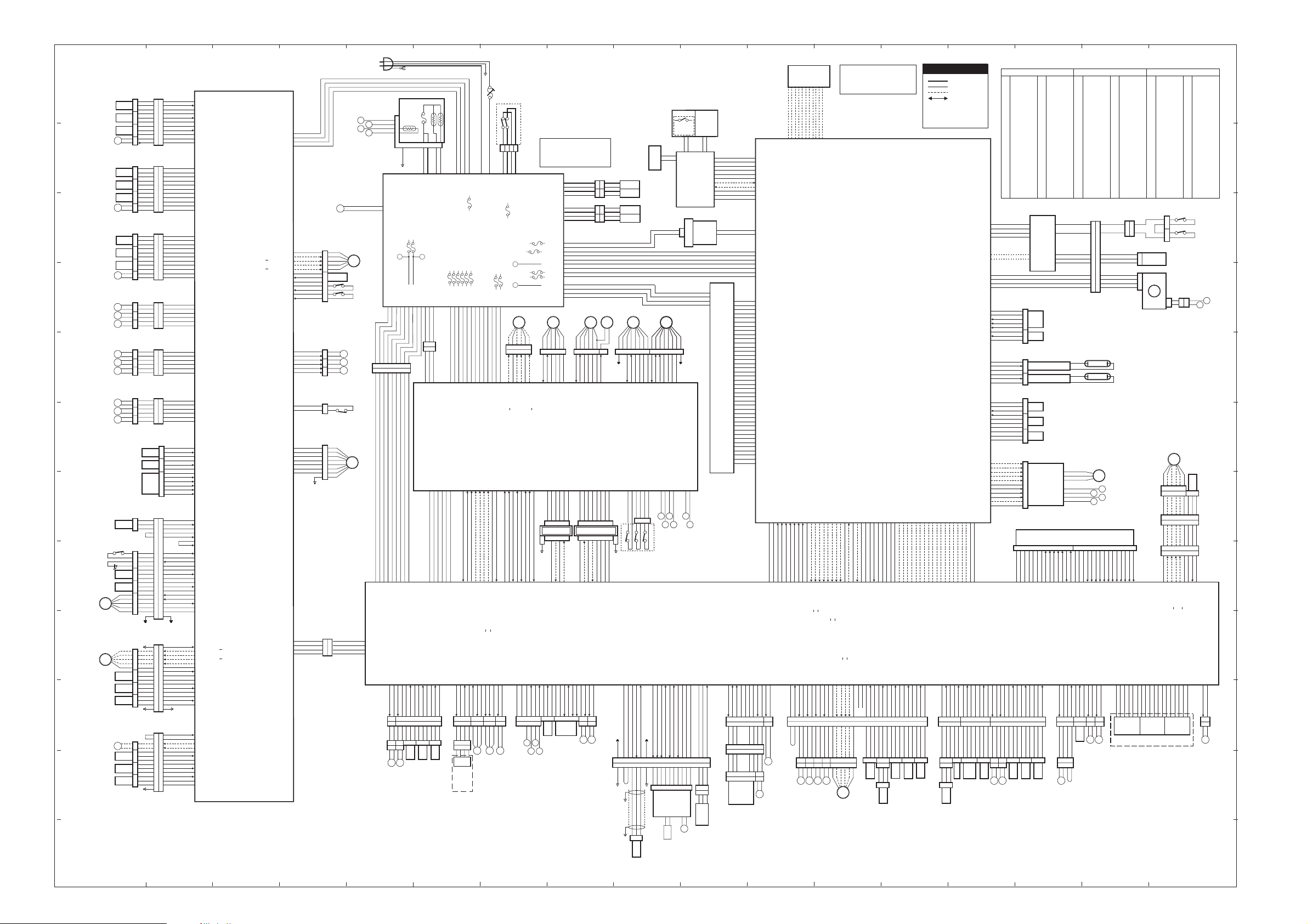
A229 P o int to Point Diagram
CN269-A1
1
3
1st Paper Feed Sensor
1st Paper End Sensor
1st Lift Sensor
1st Pick-up Solenoid
11
843 846845844
2
2
S12
S18
S15
SOL
2
10
3
1
4
3
CN809
CN809
5
2
6
1
7
3
8
2
9
1
10
2
11
1
[0] GND
-A2
[5]t
-A3
9
[5] +5V
-A4
8
[0] GND
-A5
7
[5]s
-A6
6
[5] +5V
-A7
5
[0] GND
-A8
4
[5]s
-A9
3
[5] +5V
-A10
2
[24] +24V
-A11
1
[ 24]t
111
2nd Paper Feed Sensor
2nd Paper End Sensor
2nd Lift Sensor
2nd Pick-up Solenoid
11
863
2
2
S13
S19
S16
SOL
3
10
3
1
4
3
CN810
CN810
5
2
6
1
7
3
8
2
9
1
866865864
10
2
11
3
[0] GND
-B2
[5]t
-B3
9
[5] +5V
-B4
8
[0] GND
-B5
7
[5]s
-B6
6
[5] +5V
-B7
5
[0] GND
-B8
4
[5]s
-B9
3
[5] +5V
-B10
2
[24] +24V
-B11
1
[ 24]t
CN269-B1
1
3
10
CN270-1
1
3
3rd Paper End Sensor
3rd Lift Sensor
3rd Pick-up Solenoid
11
867 870869868
2
2
S143rd Paper Feed Sensor
S20
S17
SOL
4
10
3
1
4
3
CN811
CN811
5
2
6
1
7
3
8
2
9
1
10
2
11
1
[0] GND
-2
[5]t
-3
9
[5] +5V
-4
8
[0] GND
-5
7
[5]s
-6
6
[5] +5V
-7
5
[0] GND
-8
4
[5]s
-9
3
[5] +5V
-10
2
[24] +24V
-11
1
[ 24]t
9
1st Separation Roller
Solenoid
1st Paper Feed Clutch
1st Vertical Relay
Clutch
2nd Separation Roller
Solenoid
8
2nd Paper Feed Clutch
2nd Vertical Relay
Clutch
3rd Separation Roller
Solenoid
3rd Paper Feed Clutch
3rd Vertical Relay
Clutch
7
6
3rd Paper Near End
Sensor
3rd Tray Down
Switch/LED
5
Tray Down Sensor
3rd Tray Paper Sensor
3rd Tray Lift
4
Side Fence
Motor
Side Fence Close
Sensor
Base Plate Down
Sensor
Side Plate Positioning
Sensor
3
Rear Fence Motor
Rear Fence HP Sensor
Rear Fence Return
Sensor
2
Left TandemTray Paper
End Sensor
SOL
6
MC
3
MC
9
SOL
7
MC
4
MC
10
SOL
8
MC
5
MC
11
1st Paper Near End Sensor
2nd Paper Near End Sensor
Paper Size Switch
S19
SW10
S32
S31
M14
M18
S27
S29
S28
M
17
S25
S26
S30
840
2
1
2
1
842841
2
1
2
850 852851
1
2
1
2
1
2
860
1
2
1
862861
2
1
3
871 CN872 CN875874873
2
1
1
2
4
3
1
2
3
1
3
2
3
4
5
1
2
1
CN876 877 879 890 895894893892
2
3
4
5
2
3
1
3
2
1
3
2
1
CN272-A1
1
6
[24] +24V
2
3
4
5
6
1
2
3
4
5
6
1
2
3
4
5
6
S21
S22
SW9
21
20
19
2
14
5
4
9
10
6
7
8
16
17
18
3
11
15
12
24
1
2
3
4
5
6
7
8
16
10
11
12
13
14
15
9
1
9
2
3
5
6
7
10
11
12
13
14
15
8
-A2
5
CN801
CN801
CN802
CN802
CN803
CN803
CN815825824
21
20
19
14
CN832
CN832
10
16
17
18
11
15
12
24
CN813
CN813
16
10
11
12
13
14
15
CN814
CN814
10
11
12
13
14
15
4
3
2
1
6
5
4
3
2
1
6
5
4
3
2
1
3
2
1
2
5
4
9
6
7
8
3
1
1
2
3
4
5
6
7
8
9
1
9
2
3
5
6
7
8
CN272-A7
CN272-B1
CN262-1
CN263-1
CN274-2
CN275-1
CN264-A1
CN264-B1
-A3
-A4
-A5
-A6
-A8
-A9
-A10
-A11
-A12
-B2
-B3
-B4
-B5
-B6
-2
-3
-4
-5
-6
-7
-8
-9
-10
-11
-12
-2
-3
-4
-5
-11
-12
-3
-7
-8
-4
-5
-6
-11
-12
-13
-1
-9
-10
-2
-A2
-A3
-A4
-A5
-A6
-A7
-A8
-A9
-A10
-A11
-A12
-A13
-A14
-A15
-B8
-B2
-B3
-B5
-B6
-B7
-B9
-B10
-B11
-B12
-B13
-B14
t
[ 24] +24V
[24] +24V
t
[ 24] +24V
[24] +24V
[ 24] +24V
t
[24] +24V
t
[ 24] +24V
[24] +24V
t
[ 24] +24V
[24] +24V
[ 24] +24V
t
[24] +24V
t
[ 24] +24V
[24] +24V
t
[ 24] +24V
[24] +24V
[ 24] +24V
t
[0] GND
s
[5]
[5] +5V
[0] GND
s
[5]
[5] +5V
[0] GND
t
[ 5] Paper Size 5
t
[ 5] Paper Size 4
t
[ 5] Paper Size 3
t
[ 5] Paper Size 2
t
[ 5] Paper Size 1
[0] GND
[5]s
[5] +5V
[0] GND
[5]s
3rd TrayConnection
[0] GND
[5]t
Tray Typ e
[5] Switcht
[0] GND
[ 3.5] LEDt
[5] +5V
[5] +5V
[5]s
[0] GND
[5] +5V
[5]t
[0] GND
[5]t
Up
[ 5] Downt
[5]t
Lock
[24] +24V
[0] GND
[5]s
Right TraySet
[24 24/0]:→
B
[24 24/0]: B→
[24 24/0]:→
A
[24 24/0]: A→
[24] +24V
[5]s
[0] GND
[5] +5V
[0] GND
[5]s
[5] +5V
[0] GND
[5]s
[5] +5V
[5]s
Left TraySet
[0] GND
[24 24/0] Return→
[24 24/0] Forward→
[0] GND
[5]t
[5] +5V
[0] GND
[5]s
[5] +5V
[5]t
[0] GND
[5] +5V
1
CD
E
F
G3
Power Supply Fan
M
25
Toner Collection
Motor
Toner Collection
S10
Motor Sensor
Toner Overflow Switch
Tandem Lock
SOL
9
Solenoid
2nd Tray Lift
M
13
Motor
1st Tray Lift
M
12
Motor
Lower Front Door
Safety Switch
SW6
Paper Feed
Motor
M11
CN212-1
4
CN760
3
2
1
G
H
CN1-1
CN1-2
M
9
Toner Collection
Bottle Set
Switch
SW8
TXD
-2
GND
-3
RXD
-4
GND
SW7
+24V [24]
Paper Feed
Control Board
(PCB10)
+24V [24]
A: [24 24/0]→
: [24 24/0]→
A
B: [24 24/0]→
: [24 24/0]→
B
[5 or 0 5/0]→
+24V [24]
Down [ 24]
Up [ 24]
Down [ 24]
Up [ 24]
+24V [24]
Lock
cw/ccw [ 5/cw, 5/ccw]st
Motor [ 5]t
+24VA [24]
GND [0]
GND [0]
+5V [5]
GND [0]
+5V [5]
GND [0]
GND [0]
t
[ 24]
t
t
t
t
24 VA
GND [0]
+5V [5]
GND [0]
[5]s
[5]t
[5]s
RXD
GND
TXD
GND
CN260-1
CN268-1
-2
-3
-4
-5
-6
-7
-8
-9
-10
-11
-12
CN265-1
-2
-7
-8
-9
-10
CN266-3-12
CN267-1
-2
-3
-4
-5
-6
-7
CN261-4
-3
-2
-1
-2
-3
-4
5
CN830
4
3
2
1
7
6
CN831
5
4
3
2
1
816 821 820
2
1
2
1
2
1
818
1
See Note L12
CN817
1
CN760
2
3
4
E
Thermofuse
6
(TF1)
11
8
13
Thermistor
(TH1)
CN610
FU109
Z Y
G9 G10
Fusing Lamp 2 [ 5]s
Fusing Lamp 1[ 5]s
Power Relay [24]
Fusing Zercross
+24V INT-1 [24]
+12V [12]
987654321
CN764
CN764
123456789
Fusing Unit
FU112
SWTRG
-12V [-12]
GND [0]
[5]s
-1-2-3-4-5-6-7-8-9
[*2] Fusing Lamp H 120
-4
GND [0]
-12
765
765
-3
[0]GND
L2
123
-3
[*2] Fusing Lamp H 120
+24V [24]
-11
-2
[24] +24V
F
L3
4
CN101-1
CN123-1
T102
-2
[*2] Fusing Lamp 2 N 120
[*2] Fusing Lamp 1 N 120
FU116
+24 [24]
GND [0]
CN121
321
123
CN155-1
[24]
[0] GND
T101
-2
-3
-4
[*1] ACIN-H 120
[*1] ACIN-N 0
[24] +24V
[0] GND
[0] GND
[5] +5V
FU107
FU102
FU104
FU105
FU106
FU103
+24 [24]
+24 [24]
+24 [24]
-11
-12
-13
[24]
[24]
[24]
FU113
+24 [24]
+24 [24]
GND [0]
GND [0]
GND [0]
GND [0]
GND [0]
+5V [5]
-10
-9
-11
-10
-9-8-7-6-5-4-3-2-1
[5]
[0]
[0]
[0]
[0]
[0]
[24]
[24]
Interface Board (PCB9)
+24V INT-1 [24]
+24V [24]
GND [0]
GND [0]
+5V [5]
+5V [5]
CN153-1
-2-3-4-5-6
CN205-9
-8-7-6-5-4-3-2
-1
[5] SWTRGs
[0] GND
[-12] -12V
[12] +12V
Fusing Zerocross
[ 5] Fusing Lamp 2 ONs
[ 5] Fusing Lamp 1 ONs
[ 24] Power Relays
[24] +24V INT-1
+24V [24]
+24V [24]
GND [0]
+5V [5]
+5V [5]
[ 24]
[ 24]
t
t
[5]
s
-B10
-B11
-B12
-B13
-B7
-B8
-B9
766
CN720 CN767 680 679 678 CN666 622 672
766 CN720 CN767 680 679 678 CN611
10
11
2
1
677
725
726 727 728 676
677
725
S43
SOL
M
Tray Paper Limit Sensor
13
20
Optics Cooling Fan
Duplex Inverter Solenoid
[5]
t
-B6
S42
Exit Sensor
CN200-1
-2-3-4-5-6
+24V [24]
GND [0]
GND [0]
+5V [5]
[0]s
[5]
t
CN204-B1
-A12
-B2
-B3
-B4
-B5
11
10
1
98765432121
123456789
1
3213213212112
4
676
S41
Fusing Exit Sensor
C02
-B8
-B7
-B6
-B5
-B4
-B3
-B2
-B1
-B2
-B3
-B4
-B5
-B6
-B7
-B8
-B9
[ 5] Front Door Safety Sw.s
[0] GND
[5 5/0] Registration M.:→
[5 5/0] Registration M.:→
[5 5/0] Registration M.: B→
[5 5/0] Registration M.: A→
Registration M. Speed
[ 5] Fusing/Duplex Motort
[ 5] Fusing Duplex Motor Locks
A
B
Speed ]tH24-13 L24-0
Lock [ 5]s
+24V [24]
+24V [24]
Set [ 0]s
GND [0]
[ 24]s
[ 24]t
-A10
-A11
Key Counter
-A3
-A4
-A5
-A6
-A7
-A8
-A9
432
123
M
M22M
21
Polygonal Mirror Motor Cooling Fan
Exhaust Fan
G
Circuit Braker
(CB1)
Main Power Switc h
(SW1)
*1
CN100-1
*2
-2-3-4
[*1] AC-H 120
[*1] AC-N 0
[*2] SW ON-H
[*2] SW ON-N 0
PSU
(PCB2)
Fu101 120
FU115
+24V [24]
FU108
FU114
F10
-12V [-12]
Y
FU111
FU110
+12V [12]
Z
E10
+5V [5]
CN122-1
Registration
By-pass Feed
Motor
-2-3-4-5-6-7-8
M16 M15
CN751
CN751 CN703 CN102 CN702 CN701
12345
CN151-12
-13
[5]
CN156-B9
CN203-B1
+24V [24]
[ 24]t
-A2
23
Fusing Fan
6
[24 24/0]:
→
B
-A3
-A2
-A7
-A8
[ 4/cw/ 4/ccw] cw/ccwst
[ 5] Drum Motort
CN204-A1
21321321432
8
CN155-4
-14
-5-6-7-8-9
[ 5] Locks
[24 24/0]:
[24] +24V INT-2
[24 24/0]: A
[24 24/0]: B
[24] +24V INT-2
→→→
A
CN156-A9
-A8
-A7
-A6
-A5
-A4
CN203-A1
-A2
-A3
-A4
-A5
-A6
[ 5] Dev.Motor Locks
[ 24] Toner Supply Clutcht
[ 4.3] Development Mo to rt
[ 5] Paper Feed/By-pass Feed M.Locks
[ 5] Paper Feed/By-pa s s Feed Motort
[ 5] Drum Motor Locks
Fusing Unit Set [ 5]s
Thermistor
GND [0]
GND [0]
+5V [5]
[5]
[0]
-B3
-B4
-B5
-B6
-B7
-B8
-B9
4
3
H F
G
E
E11
H
220/240V machine: [220/240]
150V machine: [115]
220/240V machine: [ 220/240]
115V machine: [ 115]ss
CN102-1
-4
-2
-5
CN103-1
-4
-2
-5
CN124-2
+5V [5]
-8
GND [0]
-14
-5
GND [0]
-6
GND [0]
-11
-7
GND [0]
-1
+5VE [5]
-3
+5V [5]
-9
-12
GND [0]
-13
GND [0]
-4
+5V [5]
Development
Motor
Motor
12345
-10
-11
-12
-8
-9
-7
[0] GND
[ 5] Motort
[ 5] Locks
[24] +24V INT-2
[0] GND
[5] +5V
[0] GND
[ 5] Motort
+24V [24]
+24V [24]
+24V [24]
-A8
1
[5 or 0 5/0]→
-B2
S11
Recycle Toner Sensor
-A7
CN694
ARDF
CN761
2
-12
[0] GND
GND [0]
CN207-B1
32165
+24V [24]
+24V [24]
GND [0]
GND [0]
GND [0]
CN154-A3
-B7
-B8
-A4
-A5
-A6
65432
1
FINISHER
2
543
CN202-9
-10
-11
RXD
[0] GND
TXD
[0] GND
RXD
Development Bias [ 24]t
Drum Erase ON [ 24]t
FB Bias Voltage
+24V INT-1 [24]
+24V INT-1 [24]
PWM-Bias
GND [0]
[ 24]t
-A10
-A3
-A4
-A5
-A6
-A7
-A8
-A9
1
CN661
672
PP2
Development P.P.
M6CO
Toner Supply Motor
614 615
614
1
2
1
2
1
2
1
2
615 612
612 613
613
Toner Supply
Clutch
H2
H1
H4
H3
Fusing/Duplex
Motor
M5 MC1 M8 M4
6123458
CN157-6
-13
-1-2-3-4-5
[ 24]t
[24] +24V INT-2
[0] GND
[5] +5V
+24V [24]
-B6
CN693
CN762
[0] GND
[ 24]t
-A2
674
674
GND [0]
GND [0]
-B5
[0] GND
TXD
+24V [24]
CN207-A1
212165432
1
Mechanical Counter
[ 5] Motort
[5]s
Lock
TonerSupply Clutch
Not Used
Not Used
GND [0]
GND [0]
CN154-B1
-B2
-B3
-B4
8765432
9876543
CN202-1
-2-3-4-5-6-7-8
[5] +5V
[5] +5V
[0] GND
Drum Unit Set [ 5]s
GND [0]
-B14
-B15
I
Operation Panel 1
Drum Heater
Optic
Anti-Condensation
Heater
Tray H ea te r 2
Tray H ea te r 1
-10
-11
-12
-9
[24] +24V INT-1
[0] GND
[5] +5V
[0] GND
[ 24]t
+24V INT-2
+24V INT-1[ 24]t
Door Open [ 5]s
+24V [24]
[ 24]t
-1-5-2-3-4
ID Sensor LED
ID Sensor
+5V [5]
-B11
-B12
-B13
664
ID Sensor
S8
LCD
Drum Motor
[ 5] Motort
[ 5/cw, 5/ccw] cw/ccwst
[ 5] Locks
+24V [24]
GND [0]
CN152-6
DB
Front Cover Safety
Switch (SW4)
Cleaner Motor Reverse [ 0]s
Cleaner Motor Forward [ 0]s
Quencing Lamp [ 14V]t
-B10
-B8
-B9
101115161718192413
9
CN660
CN660
101113151617181924
9
10
Charge P.P.
PCB11
Operation
1
2
CN158-1
-2-3-4-5-6-7-8
[24] +24V INT-1
[0] GND
[5] +5V
[0] GND
+24 [24]
GND [0]
+5V [5]
CN160-1
-2-3-4
C
AKL
P6 Q9
FB-Charge Current
FB-Grid Voltage
Charge PWM
Grid PWM
-B5
-B6
-B7
CN673
PP1
L4
Quenching Lamp
Switch
(SW2)
LCD Control
Board
(PCB13)
Mother Board
PCB15
616
CN617-1
712345681234587
+24 [24]
GND [0]
CN159-1
-2
24V INT-1 [24]
ANGND [0]
GND [0]
CN206-B1
-B2
-B3
-B4
2345678
2345678
123456789
M
7
Charge Wire Cleaner
Motor
PCB12
PCB16
+12V [12]
-A14
665
665
GND [0]
S6
Drum Potential Sensor
-2
-3
-4
Drum Potential Sensor
-A13
-A12
202122
202122
123
J
Operation Panel 2
CN441-11
Printer Controller
[12]
[0]
[0]
[5]
HDD
PWM-Transfer
K
SBU
(PCB4)
[ 5] Operation Swt
CN303-1
LED +2.0
-10
-2
[0] GND
-9
-3
[0] GND
-8
-4
OPRTS
-7
-5
ORCTS
-6
-6
RXD
-5
-7
TXD
-4
-8
[5] +5V
-3
-9
[5] +5V
-2
-10
[24] +24V
-1
-11
CN308
CN301-1
[24]
-2
[0]
-3
[0]
-5
[-12]
-6
[0]
-7
[5]
-8
[5]
CN310-1
RESET
-2
GND
-3
HDT7
-4
HDT8
-5
HDT6
-6
HDT9
-7
HDT5
-8
HDT10
-9
HDT4
-10
HDT11
-11
HDT3
-12
HDT12
-13
HDT2
-14
HDT13
-15
HDT1
-16
HDT14
-17
HDT0
-18
HDT15
-19
GND
-20
NC
-21
DMARQ
-22
GND
-23
XD10W
-24
GND
-25
XD10R
-26
GND
-27
10RDY
-28
NC
-29
XDMACK
-30
GND
-31
INTRQ
-32
X10CS16
-33
ADDR1
-34
NC
-35
ADDR0
-36
ADDR2
-37
XCS1FX
-38
XCS3FX
-39
NC
-40
GND
-40
-41
-42
-43
-44
-45
-46
-47
-48
-49
-50
-40
-41
-42
-43
-44
-45
-46
-47
-48
-49
-50
Jogger Motor:
GND
AN6: Cleaner Motor/By-pass Size
AN5: Drum Potential/TD Sensor
AN4: ID Sensor
AN3:Thermistor
AN2: FB-TransferVoltage
AN1: FB-Charge/Transfer Current
AN0:FB-Bias/Grid Voltage
GND
GND
B
FB-Transfer Current
FB-TransferVoltage
24V INT-1 [24]
ANGND [0]
+24V [24]
+24V [24]
[24]t
[24]t
0V
5V
-A8
CN669
CN669
Tra ns fe r P. P.
CN206-A1
-A2
-A3
-A4
-A5
-A6
-A7
219876321
663
663
1234789
9876321
1234789
Duplex Cooling Fan
M
24
21543
670
670
SOL
1
Transfer Belt Solenoid
-A10
-A11
-A9
2
CN671
CN671
PP3
+24V [24]
+24V [24]
Set [ 5]s
GND [0]
[24]t
[24]t
-A11
-A12
-A13
-A14
-A15
-A16
17
738
738
MC
8
DuplexTransport Clutch
Duplex Feed Clutch
L
Note: Because the paper feed motor
is ground switched, pins CN266-1
and CN267-7 will remain 2 4 V u n til
the start key is pressed. To verify
operation of SW6, unplug CN267.
CN304
-31
-32
-33
-34
-35
-36
-37
-38
-39
-31
-32
-33
-34
-35
-36
-37
-38
-39
TXD
GND
Registration Motor:A
Registration Motor:B
Registration Motor:
Registration Motor:
Jogger Motor: A
Jogger Motor: B
Jogger Motor:
A
A
B
A
B
A: [24 24/0]→
B: [24 24/0]→
: [24 24/0]→
: [24 24/0]→
+24V [24]
+24V [24]
+24V [24]
[24]t
[24]t
-A10
SOL
10
Duplex Inverter Gate Solen o id
-A2
-A3
-A4
-A5
-A6
-A7
-A8
-A9
CN730CN668
CN730CN668
SOL
11MC7
Reverse Roller Soleno id
M19
Jogger Motor
SBICU
(PCB1)
-25
-26
-27
-28
-29
-30
-25
-26
-27
-28
-29
-30
INT:GATEX
Converter ON
INT:Registration Sensor
INT:Zerocross
GND
RXD
GND
+24V [24]
GND [0]
GND [0]
+5V [5]
[5]
t
CN208-A1
-B13
-B14
-B15
S33
Duplex Entrance Sensor
M
Signal Table
< >
s
t
[ ]
-10
-11
-12
-13
-14
-15
-16
-17
-18
-19
-20
-21
-22
-23
-24
-18
-19
-20
-21
-22
-23
-24
A0: GATEX
PS: GATEX
R/W: GATEX
RST: GATEX
GND
RESET:Fusing
CLR: Fusing
GND [0]
GND [0]
+5V [5]
+5V [5]
[5]
[5]
[5]
t
t
t
-B10
-B11
-B12
-B6
-B7
-B8
-B9
101112131415323130292827262524232221201918
734CN736770739737
S34
S35
DuplexTransport Sensor 2
DuplexTransport Sensor 1
S36
DuplexTransport Sensor 3
-9
-10
-11
-12
-13
-14
-15
-16
-17
-9
D2: GATEX
D1: GATEX
D0: GATEX
CS: GATEX
CS: GATEX
CS: GATEX
A3: GATEX
A2: GATEX
A1: GATEX
Paper Size
GND [0]
+5V [5]
+5V [5]
+5V [5]
[5]
s
CN208-B1
-B11
-B12
-B2
-B3
-B4
-B5
CN742
CN742
5
123456789
12312312312312365432121212121
749
S37
Duplex Jogger HP Sensor
PCB14
By-pass Paper Size Board
AC Line
DC Line
Pulse
Signal Direction
Signal Direction
Ready Low
Ready High
Voltage
Width 1 [ 5]
Width 2 [ 5]
Width 3 [ 5]
D7: GATEX
D6: GATEX
D5: GATEX
D4: GATEX
D3: GATEX
ANGND [0]
TD Sensor
GND [0]
GND [0]
[5]s
-B10
-B7
-B8
-B9
SW11
By-pass Tray Switch
N
CN304 (L11) CN306 (N9) CN308 (J10)
1
-12V
2
-12V
3
+12V
4
+12V
5
+5V
6
+5V
7
+5V
8
+5V
9
SOVT
10
XSSCAN
11
SIN
12
XSLEAD
13
XCS
14
XRDSYNC
15
SCLK
16
XOPBSYNC
17
GND
18
GND
19
CLKU
20
GND
21
GND
22
GND
23
XCLK
24
GND
25
GND
CN402-4
CN307-1
+5V [5]
-2
+5V [5]
-3
GND [0]
-4
GND [0]
CN306 CN404-1
CN309
CN312-1
GND [0]
-2
+5V [5]
-3
t
-4
t
-5
t
-6
GND [0]
-7
[5]
s
-8
+5V [5]
CN315-1
+24V [24]
+24V [24]
+12V [12]
+24V [24]
-2-3-4-5-6-7-8
-2-3-4-5-6-7-8
GND
+12V [12]
-B5
-B6
CN741
CN741
S7
Toner Density Sensor
GND [0]
+5V [5]
+5V [5
GND [0]
GND [0]
GND [0]
XDA0
XDA1
XDA2
XDA3
XDA4
EXSEL
CN302-1
CN201-1
GND
GND [0]
[0 ~ 5]
-B4
[0]
[24]
[0]
[24]
t
[5]
t
[5]
GND
OEB
DIR
CKI
GND
+5V [5]
[5]s
CN211-B1
-B2
-B3
12345671234
S9
Toner End Sensor
CN314-1
CN305-7
CN311-1
+24V [24]
[24]t
-A13
13
746
746
5
By-pass Pick-up Solenoid
-2
-3
-4
-5
-6
-2
-3
-6
-5
-4
-3
-2
-1
-2
-3
-4
-5
-6
-7
-8
-9
-10
-11
+24V [24]
+5V [5]
[24]t
[5]t
-A10
-A11
-A12
-A9
101112
745
745
S38
MC6SOL
Relay Sensor
By-pass Feed Clutch
CN401
5
4
3
2
1
3
2
1
3
2
1
3
2
1
11
10
[0] GND
GDN [0]
-A8
CN740
CN740
9
8
7
6
5
4
3
2
1
-B13
-B14
[0] GND
+5V [5]
-A6
-A7
26
27
28
29
30
31
32
33
34
35
36
37
38
39
40
41
42
43
44
45
46
47
48
49
50
LDDR
+5V [5]
-3
-2
+5V LD [5]
-1
PCB8
XDEPT
+5V [5]
GND [0]
CN781 780 783 784 786 CN612
S2
S1
PCB6
PCB6
S4
782 785
S3
PCB7
Scanner Motor
Drive Board
(PCB5)
+24V [24]
-B10
-B11
-B12
-B8
-B9
[24] +24V
[24] +24V
[24] +24V
[24] +24V
[0] GND
GND [0]
GND [0]
+5V [5]
[5]t
[5]s
CN211-A1
-A2
-A3
-A4
-A5
123456789
3213213212121321432121321
S39
S21
Registration Sensor
By-pass Paper End Sensor
O
GND
ADE7
ADO7
ADE6
ADO6
GND
GND
ADE5
ADO5
10
ADE4
11
ADO4
12
GND
13
GND
14
ADE3
15
ADO3
16
ADE2
17
ADO2
18
GND
19
GND
20
ADE1
21
ADO1
22
ADE0
23
ADO0
24
GND
25
Not Used
CN403-1
-3
-2
-3
Original Width Sensor
Scanner HP Sensor
Original Length Sensor 2
Original Length Sensor 1
DC/DC Converter Board
CN611-1
CN610-1
GND [0]
+5V [5]
GND [0]
LCT
1413121110
987654321
-A15
-B1
-B2
-B3
-B4
-B5
-B6
-B7
[0] GND
[ 4.3V] LCT Motort
[ 5] Motor Locks
[ 24] Lift Motor:+s
[ 24] Lift Motor:-s
[ 24] Pick-up Solenoidt
[ 24] Relay Clutcht
[ 24] Paper Feed Clutcht
Set [ 5]s
GND [0]
+5V [5]
[ 24]t
[+24]
-10
-11
-9
123
4
432
1
CN755748744747743CN721750749731732733735 734CN736770739737
CN755
M
10
Toner Recycle Motor
1
GND
2
XALLRST
3
GND
4
VDSDO
5
GND
6
BDSDI
7
GND
8
SCLK
9
GND
XVDCS
GND
REFCLK
GND
XDE3
GND
XDE2
GND
XDE1
GND
XDE0
GND
XDO3
GND
XDO2
GND
-2
-3
-2
-3
-4
-A13
-A14
[ 5] Down Switcht
[5] LEDt
[5] +5V
GND [0]
[ 24]t
[5]s
S40
SOL
Guide Plate Position Sensor
P
REV. 6/3/99
XDO1
GND
XDO0
GND
SE
GND
SO
GND
XFGATE
GND
XLGATE
GND
XLSYNC
GND
PCLK
GND
XLDSYNC
GND
LDOFF
GND
LDERRO
GND
DROPEN
LD2-OFF
LD1-OFF
CN715
CN715
1
NC
2
NC
3
Not Used
4
Not Used
5
TDX-PRN
6
RXD-PRN
7
GND
8
Not Used
9
GND
10
Not Used
11
Not Used
12
Not Used
13
GND
14
Not Used
15
Not Used
16
XAWKD0
17
XAWKD1
18
XAWKD2
19
XAWKD3
20
XAWKD4
21
XAWKD5
22
XAWKD6
23
XAWKD7
24
GND
25
XARCLK
1
2
1
3
1
2
712 711
LSD1
26
27
28
29
30
31
32
33
34
35
36
37
38
39
40
41
42
43
44
45
46
47
48
49
50
CN713
CN713
M2
Polygnal Mirror Motor
L1
Exposure Lamp
L1
Q
GND
26
XARLGT
27
XARLSYC
28
XARFGT
29
XWRSYNC
30
XFSYC
31
GND
32
XARKD0
33
XARKD1
34
XARKD2
35
XARKD3
36
XARKD4
37
XARKD5
38
XARKD6
39
XARKD7
40
XOEN
41
GND
42
XDATA-IN
43
NC
44
NC
45
NC
46
NC
47
NC
48
NC
49
NC
50
Front Cover Safety Switch
693692
SW3
SW5
Laser Synchronization Detector
716
716
711
L
12
111
10
9
K
J6
8
7
LD Positioning Motor
M3
Scanner Motor
M1
A
B
I6
C
D
CN756CN757
-A10
-A11
-A12
[ 5] Paper End Sensort
[5] Cover Switchs
[ 5] LCT Connections
1514131211
10
987654321
CN210-A1
-A2
-A3
-A4
-A5
-A6
-A7
-A8
-A9
[ 5] Paper Feed Sensort
[ 5] Near End Sensors
[ 5] Paper Height Sensor 1t
[ 5] Paper Height Sensor 2t
[ 5] Paper Height Sensor 3t
[ 5] Lift Sensors
[ 5] Down Sensors
-1
[12 12/0]: A
[12] +12V
[ 5] Paper Position Sensort
→
(PCB3)
+24V [24]
+24 [24]
GND [0]
[ 24]t
RXD
NC
CN209-1
-2-3-4-5-6-7-8
752753754CN763
752753754CN763
CSS2
MC
12
12
Relay Clutch
Guide Plate Solenoid
GND [0]
TXD
-2-3-4-5-6
GND [0]
+5V [5]
RXD
NC
CN213-1
Not Used N/A
GND [0]
+5V [5]
TXD
NC
CN214-1
-2-3-4-5-6
CN714
[12 12/0]:
A
IOB
GND [0]
CSS1CSS2
CN769
CN769
CN768
CN768
[12 12/0]: B
RXD
LD Unit HP
S5
Sensor
717
123123456
6
987654321
123456789
987654321
123456789
CN218-9
-8-7-6-5-4-3-2
[5]
[0] GND
[12] +12V
[12 12/0]:
s
→→→
B
5
[5] +5V
4
+24V [24]
GND [0]
+5V [5]
[ 24]t
TXD
CN259-7-8CN215-1
-2-3-4-5-6
3
2
1
667
667
MC
2
Toner Recycle Clutch
2
1
AB
CD
E
F
G
H
I
J
K
L
M
N
O
P
Q
Page 2

COPIER (A229) ELECTRICAL COMPONENT LAYOUT (1/2)
96
14
13
12
11
10
1
2
3
49
4
5
6
48
7
8
9
50
47
37
38
46
39
40
41
42
43
44
45
82
81
80
79
65
78
66
77
67
72
76
68
71
75
69
74
70
73
109
108
107
106
105
131 132
130
129
128
104
97
98
99
100
101
102
103
110 111 112
113
114
115
116
117
118
119
120
35
34
33
32
31
30
36
15
51
52
16
17
18
19
20
21
22
23
24
25
2829
27
26
64
63
62
61
60
53
54
59
55
56
57
58
86
87
88
89
90
91
92
85
93
84
83
94
95
137
127
126
136
125
123
124
135
121
122
133
134
Page 3
COPIER (A229) ELECTRICAL COMPONENT LAYOUT (2/2)
Rev. 6/4/99
Symbol
Index
No.
Description P to P
Printed Circuit Board
PCB 1 23 SBICU L9
PCB 2 57 PSU G10
PCB 3 52 IOB Q4
PCB 4 21 SBU (Sensor Board Unit) K1
PCB 5 51 Scanne r Motor Drive O7
PCB 6 22 Lamp Regulator O8
PCB 7 19 DC/DC Converter O7
PCB 8 27 LDDR O10
PCB 9 64 Interface G7
PCB10 58 Paper Feed Control C11
PCB11 31 Operation Panel 1 I12
PCB12 34 Operation Panel 2 J12
PCB13 33 LCD Control J11
PCB14 101 By-pass Paper Size M2
PCB15 54 Mother (Option) J10
PCB16 55 Printer Controller(Option) J10
Motors
M 1 17 Scanner P6
M 2 25 Polygonal Mirror Q9
M 3 29 LD Positioning Q7
M 4 39 Drum I9
M 5 40 Development H9
M 6 48 Toner Supply H3
M 7 90 Charge Wire Cleaner J1
M 8 37 Fusing/Duplex I9
M 9 5 Toner Collection E10
M10 8 Toner Recycle O2
M11 46 Paper Feed E7
M12 44 1st Tray Lift D8
M13 45 2nd Tray Lift D8
M14 135 3rd Tray Lift A5
M15 43 By-pass Feed H9
M16 42 Registration G9
M17 72 Rear Fence A3
M18 77 Side Fence A4
M19 80 Jogger L2
M20 24 Optics Cooling Fan E2
M21 49 Polygonal Mirror Motor F2
Cooling Fan
M22 38 Exhaust Fan G2
M23 50 Fusing Fan G2
M24 47 Duplex Cooling Fan K2
M25 59 PSU Cooling Fan D10
Symbol
Sensors
S 1 35 Sc anner HP O 8
S 2 36 O riginal Width O9
S 3 18 O riginal Length 1 O7
S 4 20 O riginal Length 2 O7
S 5 28 LD Unit Home Position Q6
S 6 88 Drum Potential J1
S 7 95 TD N2
S 8 91 ID I1
S 9 94 Toner End N2
S10 9 Toner Collection Motor E9
S11 1 R ecycle Toner H3
S12 129 1st Paper Feed A12
S13 126 2nd P ape r F eed A11
S14 125 3rd P ap er Feed A10
S15 132 1st Lift A11
S16 128 2nd Lift A10
S17 123 3rd Lift A9
S18 130 1st Paper End A12
S19 127 2nd P ape r End A11
S20 124 3rd P ap er E nd A10
S21 99 By-pass Paper End O 2
S22 110 1st Paper Near End A7
S23 131 2nd P ape r Near End A7
S24 133 3rd P ap er Near End A6
S25 79 Rear Fenc e HP A2
S26 78 Rear Fenc e Return A2
S27 75 Side Fence Close A4
S28 74 Side Fence Positioning A3
S29 76 Base Plate Down A3
S30 73 Left Tandem Paper End A2
S31 135 3rd T ray P aper Set A5
S32 134 Tray Down A5
S33 65 Duplex Entrance L2
S34 66 Duplex Transport 1 M2
S35 68 Duplex Transport 2 M2
S36 71 Duplex Transport 3 M2
S37 69 Duplex Jogger HP M2
S38 104 Relay N2
S39 106 Registration O2
S40 105 Guide P late P osition O3
S41 107 Fusing Exit F2
S42 108 Exit F2
S43 109 Tray Paper Limit E2
Index
No.
Descriptio n P to P
Symbol
Magnetic Clutc hes
MC 1 41 Toner Supply H9
MC 2 2 Toner Recycle Q3
MC 3 112 1st Paper Feed A9
MC 4 115 2nd Paper Feed A8
MC 5 120 3rd Paper Feed A7
MC 6 100 By-pass Feed N2
MC 7 67 Duplex Transport K 2
MC 8 70 Duplex Feed K2
MC 9 113 1st Vertical Relay A9
MC10 116 2nd Vertical Relay A8
MC11 119 3rd Vertical Relay A7
MC12 103 Relay P3
Sole noids
SOL 1 92 Transfer Belt K2
SOL 2 111 1st Pick-up A11
SOL 3 117 2nd Pick-up A10
SOL 4 121 3rd Pick-up A9
SOL 5 98 By-pass Pick-up N2
SOL 6 114 1st Separation Roller A9
SOL 7 118 2nd Separation Roller A8
SOL 8 122 3rd Separation Roller A7
SOL 9 4 Tandem Lock A8
SOL10 82 Duplex Junction Gate L2
SOL11 81 Reverse Roller L2
SOL12 102 Guide Plate P3
SOL13 96 Duplex Exit Junction Gate E2
Switches
SW 1 11 Main P ower G12
SW 2 30 Operation J11
SW 3 12 Front Door Safety 1 Q10
SW 4 13 Front Door Safety 2 I5
SW 5 14 Front Door Safety 3 Q10
SW 6 10 Low er Front Door Safety D7
SW 7 7 Toner C ollec tion Bottle Set E9
SW 8 6 Toner Overflow E9
SW 9 3 Paper Size B6
SW10 136 3rd Tray Down A5
SW11 97 By-pass Tray N2
Index
No.
Description P to P
Symbol
Lamps
L 1 15 Exposure P8
L 2 86 F using 1 F12
L 3 85 F using 2 F12
L 4 89 Quenching I1
Heate rs
H 1 16 Optics Anti-condensation I11
H 2 63 Drum I11
H 3 62 Tray 1 I10
H 4 60 Tray 2 I10
Power Packs
PP 1 87 Charge I2
PP 2 56 Development H3
PP 3 93 Transfer J2
Others
CB 1 61 Circuit Braker G12
HD D 1 53 HDD J8
LCD 1 32 LCD I11
LSD 1 26 Laser Sync hroniz ation Detec tor Q10
TF 1 84 Fusing Thermofuse F12
TH 1 83 Fusing Therm is tor E11
TP 1 32 T ouch Panel -
Index
No.
Description P to P
Page 4

1234567891011121314
POINT TO POINT DIAGRAM (FINISHER 3,000: A697)
A
A
Copier
B
C
Front Door
D
Safety Switch
Entrance
E
Sensor
Stapler Tray
Entrance
Sensor
F
Upper Tray
Exit Sensor
Upper Tray
G
Paper Limit
Sensor
H
Shift Tray
Exit Sensor
Paper Height 1
I
Sensor
Paper Height 2
Sensor
J
Shift Tray
Lower Limit 1
Sensor
K
Shift Tray
Lower Limit 2
Sensor
Shift Tray
L
Half-turn
Sensor
Stack Feed-
out Belt HP
M
Sensor
Jogger Fence
HP Sensor
N
Stapler Tray
Paper Sensor
O
Stapler HP
Sensor
Stapler Rotation
P
HP Sensor
Punch HP
Sensor
Q
Hopper
Sensor
R
Punch
Motor
S
T
S1
S2
S12
S13
S9
S11
S10
S15
S16
S14
S8
S3
S4
S5
S6
S18
S17
M11
SW1
CN650
CN254-1
CN204-1
CN205-1
-1
-2
-3
-1
-2
-3
-1
-2
-3
-1
-2
-3
CN267-1
CN257-1
-1
-2
-3
CN268-1
CN258-1
CN208-1
CN259-1
-1
-2
-3
CN620
-6
-1
-5
-2
-4
-3
CN620CN630
-1 -3
-2
-2
-1
-3
CN610-1
-2
-3
-2
-3
-2
-3
-2
-3
-2
-3
-2
-3
-2
-3
-2
-3
-2
-3
-2
-4
-5
-6
-7
CN266
CN256
CN206
CN206
CN207
CN209
Punch
Board
(PCB2)
CN101-1
CN102-2
CN103-1
CN104-6
CN104-3
CN105-3
-1
-2
-3
-1
-2
-3
-1
-2
-3
-4
-5
-6
-1
-2
-3
-1
-2
-3
CN106CN366
CN106CN356
CN106CN316
CN106CN306
CN107-9
CN107-6
CN107CN307
CN108-9
CN108-6
CN108-3
CN109-6
CN109CN309
-1
-2
-3
-4
-5
-6
-7
-8
-9
-10
-11
[24] 24V
-2
[24] 24V
-3
[24] 24V
-4
[0] GND1
-5
[0] GND1
-6
[0] GND1
[0] GND2
-3
RXD
-4
[0] GND2
-5
TXD
[24] 24V
-2
[▲24] Front Door Safety Switch
A
[0] GND2
-5
[▲5] Entrance Sensor
-4
[5] 5V
[5] 5V
-2
[▲5] Stapler Tray Entrance Sensor
-1
[0] GND2
[5] 5V
-2
[0] GND2
-1
[▼5] Upper Tray Exit Sensor
-13
[0] GND2
-12
[▲5] Upper Tray Paper Limit Sensor
-11
[5] 5V
-10
[0] GND2
-9
[▲5] Shift Tray Exit Sensor
-8
[5] 5V
-6
[5] 5V
-5
[0] GND2
-4
[▲5] Paper Height 1 Sensor
-3
[5] 5V
-2
[0] GND2
-1
[▲5] Paper Height 2 Sensor
[5] 5V
-8
[▲5] Shift Tray Lower Limit 1 Sensor
-7
[0] GND2
[5] 5V
-5
[▲5] Shift Tray Lower Limit 2 Sensor
-4
[0] GND2
-3
[5] 5V
-2
[▲5] Shift Tray Half-turn Sensor
-1
[0] GND2
[5] 5V
-8
[0] GND2
-7
[▲5] Stack Feed-out Belt HP Sensor
[5] 5V
-5
[▼5] Jogger Fence HP Sensor
-4
[0] GND2
[0] GND2
-2
[▲5] Stapler Tray HP Sensor
-1
[5] 5V
[5] 5V
-5
[▼5] Stapler HP Sensor
-4
[0] GND2
-3
[5] 5V
-2
[▼5] Stapler Rotation HP Sensor
-1
[0] GND2
CN121CN600
-11
[▲5] Hopper Sensor
-10
[▼5] Punch Unit Installed
-9
[▲5] Punch HP Sensor
-8
[▼24 0/24 ] Punch Motor B
-7
[▼24 0/24 ] Punch Motor A
-6
[▼24 0/24 ] Punch Motor B
-5
[▼24 0/24 ] Punch Motor A
-4
[0] GND2
-3
[5] 5V
-2
[0] GND1
-1
[24] 24V
A
Upper Transport Motor : A [▼24 0/24 ]
Upper Transport Motor : A [▼24 0/24 ]
Upper Transport Motor : B [▼24 0/24 ]
Upper Transport Motor : B [▼24 0/24 ]
Lower Transport Motor : A [▼24 0/24 ]
Lower Transport Motor : A [▼24 0/24 ]
Lower Transport Motor : B [▼24 0/24 ]
Lower Transport Motor : B [▼24 0/24 ]
A
Shift Tray Lift Motor : + [▲24]
Shift Tray Lift Motor : - [▲24]
Tray Junction Gate Sol. [▼24]
Shift Tray Exit Motor : A [▼24 0/24 ]
Shift Tray Exit Motor : A [▼24 0/24 ]
A
Stapler Rotation Motor : A [▼24 0/24 ]
Stapler Rotation Motor : A [▼24 0/24 ]
Stapler Rotation Motor : B [▼24 0/24 ]
Stapler Rotation Motor : B [▼24 0/24 ]
A
Stack Feed-out Motor : + [▼24]
Stack Feed-out Motor : - [▼24]
Stack Feed-out Motor F.S. [0/12]
Stack Feed-out Motor F.S. [0/12]
Shift Tray Upper Limit Switch [▲24]
Stapler Junction Gate Sol. [▼24]
Jogger Motor : A [▼24 0/24 ]
Jogger Motor : A [▼24 0/24 ]
Jogger Motor : B [▼24 0/24 ]
Jogger Motor : B [▼24 0/24 ]
Stapler Motor : A [▼24 0/24 ]
Stapler Motor : A [▼24 0/24 ]
Stapler Motor : B [▼24 0/24 ]
Stapler Motor : B [▼24 0/24 ]
Staple Hummer Motor : + [▲24]
Staple Hummer Motor : + [▲24]
Staple Hummer Motor : - [▲24]
Staple Hummer Motor : - [▲24]
A
A
A
Exit Motor : B [▼24 0/24 ]
Exit Motor : B [▼24 0/24 ]
Positioning Roller Sol. [▼24]
A
A
A
Cartridge Set Switch [▲5]
Staple End Switch [▲5]
Staple Hammer Sensor [▲5]
Stapler Installed [▲5]
24V(A) [24]
24V(B) [24]
24V(A) [24]
24V(B) [24]
A
Shift Motor [▼24]
A
A
A
24V [24]
24V(A) [24]
24V(B) [24]
24V [24]
24V [24]
24V [24]
24V [24]
24V(A) [24]
24V(B) [24]
24V(A) [24]
24V(B) [24]
24V(A) [24]
24V(B) [24]
GND2 [0]
CN110-1
CN111-1
CN112-1-2CN212-2
CN112-4-5CN222-2
CN113-1 CN213-7
CN114-1
CN115 CN315
-1
-2
CN115-3-4CN215-2
CN116-1
CN117-1
CN118-1 CN218-7
CN118-8 CN228-7
CN119-1 CN219-7
CN120-12 CN220-1
5V [5]
CN210-7
-2
-4
-5
-6
-7
CN211-7
-2
-4
-5
-6
-7
-2
-4
-5
-6
-7
CN214-5
-2
-4
-5
CN215
-4
-3
-2
-2
-2
-4
-5
-6
-7
-9
-11
-12
-13
-14
-2
-4
-5
-6
-7
-11
-9
-8
-6
-5
-4
3
-2 -11
-1
-10
-12
-6
-4
-3
-2
-1
-6
-4
-3
-2
-1
-1
-1
-6
-4
-3
-2
-1
-4
-2
-1
-2
-1
M1
M2
M10
SOL
1
M8
M7
M9
SW2
-1
SOL
2
SOL
3
-6
-4
-3
-2
-1
-6
-4
-3
-2
-1
-6
-4
-3
-2
-1
-2
-4
-5
-7
-8
-9
M3
M4
M5
M6
SW4
SW3
S7
Upper
Transport
Motor
Lower
Transport
Motor
Shift Tray
Lift Motor
Tray Junction
Gate Solenoid
Shift Tray
Exit Motor
Stack
Feed-out
Motor
Shift
Motor
Shift Tray
Upper Limit
Switch
Stapler
Junction Gate
Solenoid
Positioning
Roller
Solenoid
Jogger
Motor
Stapler
Motor
Stapler
Rotation
Motor
Stapler
B
C
D
E
F
G
H
I
J
K
L
M
N
O
P
Q
R
SYMBOL TABLE
DC Line
Pulse Signal
S
Signal Direction
Ready Low
Main Board
(PCB1)
▲
▼
[ ]
Ready High
Voltage
T
1234567891011121314
Page 5

3,000-SHEET FINISHER (A697) ELECTRICAL COMPONENT LAYOUT
26
25
24
23
22
27
21
28
29
34
33
32
31
30
35
36
37 38 1 2 3
4
5
6
7
8
9
10
11
12
13
14
15
16
17
20
Index
Symbol
Motors
M1 3 Upper Transport B13
M2 11 Lower Transport C13
M3 28 Jogger L13
M4 17 Stapler N13
M5 18 Stapler Rotation O13
M6 24 Staple Hammer Q13
M7 29 Stack Feed-out H13
M8 2 Shift Tray Exit G13
M9 31 Shift I13
M10 1 Shift Tray Lift E13
M11 6 Punch S2
Sensors
S1 9 Entrance E2
S2 14 Stapler Tray Entrance F2
S3 27 Jogger Fence HP N2
S4 25 Stapler Tray Paper N2
S5 20 Stapler HP O2
S6 19 Stapler Rotation HP P2
S7 23 Staple Hammer HP R13
S8 26 Stack Feed-out Belt HP M2
S9 32 Shift Tray Exit H2
S10 34 Stack Height 1 I2
S11 33 Stack Height 2 J2
S12 38 Upper Tray Exit F2
S13 37 Upper Tray Ppaer Limit G2
S14 30 Shift Tray Half-turn L2
S15 15 Shift Tray Lower Limit 1 J2
S16 16 Shift Tray Lower Limit 2 K2
S17 8 Hopper R2
S18 7 Punch HP Q2
No.
Description P to P
12
19
18
Index
Symbol
Switches
SW1 13 Front Door Safety D2
SW2 35 Shift Tray Upper Limit J13
SW3 21 Staple End R13
SW4 22 Cartridge Set Q13
Solenoids
SOL1 4 Tray Junction Gate E13
SOL2 36 Stapler Junction Gate J13
SOL3 12 Positioning Roller K13
PCBs
PCB1 10 Main T6
PCB2 5 Punch Q4
No.
Description P to P
11
Page 6

LCT (A698) ELECTRICAL COMOPONENT LAYOUT
AUTO DOCUMENT FEEDER (A806)
3
2
4
5
6
ELECTRICAL COMOPONENT LAYOUT
7
1
8
24
1
23
9
22
2
3
4
5
6
7
10
8
9
11
21
10
12
20
21
13
19
18
17
16
14
15
A698D102.WMF
20
19
18
17
16
15
14
11
12
13
A806D102.WMF
Symbol
Magnetic Clutches
MC1 5 Paper Feed
MC2 4 Relay
Switches
SW1 16 Tray Cover 1
SW2 17 Tray Cover 2
SW3 18 Tray Cover 3
SW4 7 Feed Unit Cover 1
SW5 8 Feed Unit Cover 2
SW6 19 Down
Solenoids
SOL1 3 Pick-up
PCBs
PCB1 13 LCT Interface
Index
Description P to P
No.
R13
S13
N4
O4
O2
M4
N4
N12
P13
T7
Symbol
Motors
Sensors
Index
Description P to P
No.
M1 6 LCT R2
M2 14 Lift P2
S1 21 Paper End E13
S2 1 Paper Feed M14
S3 2 Lift L14
S4 15 Down D13
S5 10 Paper Height 1 I13
S6 11 Paper Height 2 H13
S7 12 Paper Height 3 F13
S8 9 Near End J13
S9 20 Paper Position B13
Symbol
Sensors
Index
Description P to P
No.
S1 9 APS Star t
S2 10 DF Position
S3 23 Original Set
S4 17 Bottom Plate HP
S5 24 Bottom Plate Position
S6 1 Pick-up Roller HP
S7 22 Entrance
S8 18 Registration
S9 21 Original Width-1
S10 20 Original Width-2
S11 19 Original Width-3
S12 15 Exit
S13 14 Inverter
S14 3 Feed Co ver
S15 12 Exit Cover
Symbol
Motors
S13
R13
D13
E13
L13
K2
Solenoids
M13
SOL1 13 Exit Gate Q2
B13
F13
SOL2 16 Inverter Gate R2
G13
PCBs
H13
PCB1 8 Main T7
N13
PCB2 4 DF Indicator P2
Q13
I13
O13
Index
Description P to P
No.
M1 2 Pick-up J2
M2 6 Feed-in F2
M3 7 Transport H2
M4 11 Feed-out N2
M5 5 Bottom plate L2
Page 7

1234567891011121314
y
A
POINT TO POINT DIAGRAM (LCT: A698)
B
C
D
E
F
Copier
G
H
I
J
K
L
CN103-14
-13
-12
-11
-10
-9
-8
-7
-6
-5
-4
-3
-2
-1
CN103-15
-14
-13
-12
-11
-10
-9
-8
-7
-6
-5
-4
-3
-2
-1
CN100-1
-6
-10
-11
-12
-13
-14
CN101-1
-2
-3
-4
-5
-6
-7
-8
-9
-10
-11
-12
-13
-14
-15
[0] GND
-2
[0] GND
-3
[0] GND
-4
[24] +24 V
-5
[24] +24 V
[24] +24 V
-7
[24] +24 V
-8
[▼24] Paper Feed Clutch
-9
[▼24] Relay Clutch
[▼24] Pick-up Solenoid
[▲24] Lift Motor: [▲24] Lift Motor: +
[▲5] LCT Motor Lock
[▲24] LCT Motor
[0] GND
[5] +5 V
[▼5] LED
[▲5] Down Switch
[▲5] LCT Connection
[▲5] Cover Switch
[▼5] Paper End Sensor
[▼5] Down Sensor
[▲5] Lift Sensor
[▲5] Paper 3 Height
[▲5] Paper 2 Height
[▲5] Paper 1 Height
[▲5] Near End Sensor
[▼5] Paper Feed Sensor
[▲5] Paper Position Sensor
+5V [5]
[▼5]
GND [0]
GND [0]
[▲5]
+5V [5]
GND [0]
[▼5]
+5V [5]
GND [0]
[▲5]
+5V [5]
GND [0]
[▲5]
+5V [5]
GND [0]
[▲5]
+5V [5]
GND [0]
[▲5]
+5V [5]
GND [0]
[▲5]
+5V [5]
CN305-1
-2
-3
CN303-1
-2
-3
CN303-4
-5
-6
CN302-1
-2
-3
CN302-4
-5
-6
CN302-7
-8
-9
CN302-10
CN301-7
-8
-9
-11
-12
-2
-1
-5
-4
CN207-3
CN258-1CN218-3
CN217-3
CN215-3
CN214-3
CN213-3
CN212-3
CN223-3CN210-6
-2
-1
-2
-1
-2
-1
-2
-1
-2
-1
-2
-1
-2
-1
-2
-1
S9
S4
S1
S7
S6
S5
S8
CN225-3
Paper Position
Sensor
Down Sensor
Paper End
Sensor
Paper Height
Sensor 3
Paper Height
Sensor 2
Paper Hight
Sensor 1
Near End
Sensor
-2
S3
-1
A
B
C
D
E
F
G
H
I
J
K
Lift
Sensor
L
M
N
O
P
Q
R
S
T
Tray Cover 3
Switch (SW3)
Lift Motor
LCT Motor
Signal Direction
< >
V
W
Signal Dirction
Ready Low
Ready High
Feed Unit Cover 1 Switch (SW4)
Tray Cover 1 Switch (SW1)
Feed Unit Cover 2 Switch (SW5)
Tray Cover 2 Switch (SW2)
M2
-3
-1
-4
-5
-8
[ ]
CN211-7
-6
-5
-4
-3
-1
AC Line
Puls
Voltage
CN202-2
M1
Signal Table
CN300-9
CN300-10
CN300-7
CN300-5
CN300-3
CN300-2
CN300-1
CN304-1
[0] GND
[▲5] Cover Switch
[▲24] Lift Motor : +
[0] GND
-[▲24] Lift Motor:
[0] GND
-2
[5] +5 V
-3
[24] +24 V
-4
[0] GND
-5
[▼24] LCT Motor
-7
[▲5] LCT Motor Lock
PCB1
(LED) [3.5]
+5V (LED) [5]
Down Switch [▼5]
GND (Switch) [switch]
LCT Interface Board
GND [0]
[▼5]
+5V [5]
[24]
[▼24]
[24]
[▼24]
[24]
[▼24]
CN301-10
-11
-12
CN303-7
-8
-9
-10
CN301-1
-2
-3
-4
-5
-6
CN210-3
-2
-1
CN210-12
-11
-10
-9
-8
-7
CN224-3
CN216-4
CN220-2
-1
CN221-2
-1
CN222-2
-1
-2
-1
-3
-2
-1
CN226-3
SW6
SOL1
MC1
MC2
-2
S2
-1
Down Switch
Pick-up
Solenoid
Paper Feed
Cluth
Rela
Clutch
Paper
Feed
Sensor
M
N
O
P
Q
R
S
T
1234567891011121314
Page 8

1234567891011121314
g
g
g
g
A
POINT TO POINT DIAGRAM (ARDF: A806)
AC Line
Puls
Voltage
CN100-1
CN110-2
CN170-1
CN170-8
-11
-12
-13
-14
CN180-1
CN160-1
CN130-1
CN190-1
CN140-1
CN150-1
[24] +24V
-2
[24] +24V
-3
[24] +24V
-4
[0] GND
-5
[0] GND
-6
[0] GND
[0] GND
-3
TXD
-4
[0] GND
-5
RXD
[24] +24V
-2
[24] +24V
-4
[24 → 0/24] Motor: A
-5
[24 → 0/24] Motor:¯A
-6
[24 → 0/24] Motor: B
-7
[24 → 0/24] Motor: B
[24] +24V
-9
[24] +24V
[24 → 0/24] Motor: A
[24 → 0/24] Motor:¯A
[24 → 0/24] Motor: B
[24 → 0/24] Motor: B
[24] +24V
-2
[24] +24V
-4
[24 → 0/24] Motor: A
-5
[24 → 0/24] Motor:¯A
-6
[24 → 0/24] Motor: B
-7
[24 → 0/24] Motor: B
[24] +24V
-2
[24 → 0/24] Motor: A
-3
[24 → 0/24] Motor:¯A
-4
[24 → 0/24] Motor: B
-5
[24 → 0/24] Motor: B
-6
[24] +24V
[24] +24V
-2
[24] +24V
-4
[24 → 0/24] Motor: A
-5
[24 → 0/24] Motor:¯A
-6
[24 → 0/24] Motor: B
-7
[24 → 0/24] Motor: B
[24]
-2
[▼24] READY
-3
[▼24] SADF
[24] +24V
-2
[▼24]
[24] +24V
-2
[▼24]
PCB1
B
C
D
E
F
Feed-in Motor
G
H
I
J
Transport
Pick-up Motor
K
L
Bottom Plate
M
N
O
DF Indicator
P
Q
R
Inverter Gate
S
T
Motor
Motor
Feed-out
Motor
Exit Gate
Solenoid
Solenoid
Signal Direction
< >
V
W
Signal Dirction
Ready Low
Ready High
Copier
M2
M3
M1
M5
M4
PCB2
SOL1
SOL2
Signal Table
CN580-3
-9
-1
-5
-7
-11
CN570-3
-9
-1
-5
-7
-11
CN560-7
-6
-4
-3
-2
-1
CN510-3
-2
-1
[ ]
¯
¯
¯
¯
¯
Main Board
GND [0]
[▲5]
+5V [5]
GND [0]
[▼5]
+5V [5]
GND [0]
[▼5]
+5V [5]
GND [0]
[▼5]
+5V [5]
GND [0]
[▼5]
+5V [5]
GND [0]
[▼5]
+5V [5]
GND [0]
[▼5]
+5V [5]
GND [0]
[▼5]
+5V [5]
GND [0]
[▼5]
+5V [5]
GND [0]
[▲5]
+5V [5]
GND [0]
[▲5]
+5V [5]
GND [0]
[▼5]
+5V [5]
GND [0]
[▲5]
+5V [5]
GND [0]
[▼5]
+5V [5]
GND [0]
[▲5]
+5V [5]
CN200-1
-2
-3
CN200-4
-5
-6
CN200-7
-8
-9
CN210-1
-2
-3
CN210-4
-5
-6
CN210-7
-8
-9
CN220-1
-2
-3
CN220-4
-5
-6
CN220-7
-8
-9
CN220-10 CN520-3CN310-3
-11
-12
CN240-1
-2
-3
CN120-1
-2
-3
CN120-4
-5
-6
CN230-1
-2
-3
CN230-4
-5
-6
-2
-1
-5
-4
-2
-1
-8
-7
-5
-4
-2
-1
-2
-1
-2
-1
CN610-3CN340-3
CN590-3CN350-6
CN600-3CN350-3
CN620-3CN360-9
CN630-3CN360-6
CN640-3CN360-3
CN550-3
CN540-3CN330-3
CN320-3
CN690-3
CN670-3
CN680-3
CN650-3
CN660-3
-2
-1
-2
-1
-2
-1
-2
-1
-2
-1
-2
-1
-2
-1
-2
-1
-2
-1
-2
-1
-2
-1
-2
-1
-2
-1
-2
-1
-2
-1
S8
S3
S4
S9
S10
S11
S14
S6
S5
S7
S12
S15
S13
S2
S1
Registration
Sensor
Ori
inal Set
Sensor
Bottom Plate
HP Sensor
inal
Ori
Width 1 Sensor
inal
Ori
Width 2 Sensor
inal
Ori
Width 3 Sensor
Feed Cover
Sensor
Pick-up Roller
HP Sensor
Bottom Plate
Position Sensor
Entrance
Sensor
Exit Sensor
Exit Cover
Sensor
Inverter Sensor
DF Position
Sensor
APS Start
Sensor
A
B
C
D
E
F
G
H
I
J
K
L
M
N
O
P
Q
R
S
T
1234567891011121314
Page 9

12
3
4
5
678 910
11 12
A
B
C
D
Proof Tray
Transport
Proof Tray
E
Junction Gate
Proof Tray
Cover
Proof Tray
F
Exit
Proof Tray
Paper Oerflow
Proof Tray
Paper 1
G
Proof Tray
Paper 2
Rev. 1/15/99
POINT TO POINT DIAGRAM (Mail Box/Bridge Unit: G909/G912)
CN4-1
CN4-2
CN4-3
CN4-4
CN4-5
CN4-6
CN4-7
CN4-8
CN4-9
CN4-10
CN2-1
CN2-2
CN2-3
CN2-4
CN2-5
CN2-6
CN2-7
CN2-8
CN30-1
CN30-2
CN30-3
CN30-4
CN30-5
CN30-6
CN30-7
CN31-1
CN31-2
CN31-3
CN31-4
CN31-5
CN31-6
CN31-7
CN32-1
CN32-2
CN32-3
CN32-4
CN32-5
CN32-6
CN32-7
CN33-1
CN33-2
CN33-3
CN33-4
CN33-5
CN33-6
CN33-7
5
5
GND
GND
TXD
GND
RXD
GND
24
24
24
GND
GND
GND
CN300-7
CN300-6
CN300-5
CN300-4
CN300-3
CN300-2
CN300-1
CN300-7
CN300-6
CN300-5
CN300-4
CN300-3
CN300-2
CN300-1
CN300-7
CN300-6
CN300-5
CN300-4
CN300-3
CN300-2
CN300-1
CN300-7
CN300-6
CN300-5
CN300-4
CN300-3
CN300-2
CN300-1
Paper 0
(S14)
Paper 1
(S15)
Paper 2
(S16)
Paper 3
(S17)
FINISHER
CN302-1
CN302-2
CN302-3
CN301-1
CN301-2
CN301-3
CN302-1
CN302-2
CN302-3
CN302-1
CN302-2
CN302-3
CN302-1
CN302-2
CN302-3
CN301-1
CN301-2
CN301-3
S24
S10
S25
S26
S27
S11
Paper
Overflow 1
Tray Exit 1
Paper
Overflow 2
Paper
Overflow 3
Paper
Overflow 4
Tray Exit 2
(S8)
(S9)
M1
SOL 1
S5
S4
S3
CN56-1
CN56-2
CN56-3
CN56-4
CN51-1
CN51-2
CN52-1
CN52-2
CN52-3
CN53-1
CN53-2
CN53-3
CN54-1
CN54-2
CN54-3
CN55-3
CN55-4
CN55-2
CN55-1
[ 24] A
st
[ 24]/A
st
[ 24] B
st
[ 24]/B
st
[24]
[ 24] Junction Gate Sol.t
[5]
GND
[ 5] Tray Cover Sn.t
[5]
GND
[ 5] Tray Exit Sn.t
[5]
GND
[ 5] Paper Overflow Sn.t
GND
[5]
[ 5] Paper Sn.s
[5]
COPIER
PROOF
TRAY
CONTROL
(PCB 2)
Bridge Unit
CN50-15
CN50-14
CN50-13
CN50-12
CN50-11
CN50-10
CN50-9
CN50-8
CN50-7
CN50-6
CN50-5
CN50-4
CN50-3
CN50-2
CN50-1
24
24
24
GND
GND
GND
5
5
GND
GND
TXD
GND
RXD
GND
CN1-1
CN1-2
CN1-3
CN1-4
CN1-5
CN1-6
CN1-7
CN1-8
CN1-9
CN3-9
CN3-8
CN3-7
CN3-6
CN3-5
CN3-4
CN3-3
CN3-2
CN3-1
CN5-1
CN5-2
CN5-3
CN5-4
CN5-5
CN5-6
CN5-7
CN5-8
CN5-9
CN5-10
CN5-11
CN5-12
CN5-13
CN5-14
CN5-15
MAIN CONTROL
(PCB 1)
[24]
[24]
GND
GND
[5]
GND
[5]
[ 5] Proof Tray Cover Sn.
t
[ 5] Joint
t
[ 24] Junction Gate Sol.
s
[ 5] Proof Tray Exit Sn.
s
[ 5] Paper Overflow Sn.
s
[ 5] Paper Sn.
t
[ 5] Motor Enable
s
[5] Motor Clock
GND
[ 5] Paper Overflow 1 Sn.
st
[5]
st
st
st
[5]
st
st
[5] Tray Exit 2 Sn.
GND
GND
GND
[ 5] Paper 1 Sn.
[ 5] Paper Overflow 2 Sn.
st
[ 5] Paper 2 Sn.
[ 5] Paper Overflow 3 Sn.
st
[ 5] Paper 3 Sn.
[ 5] Paper Overflow 4 Sn.
st
[5]
[5]
[5]
NC
NC
[5]
NC
NC
[5]
NC
[5]
NC
[5]
[5]
A
B
C
D
E
F
G
H
J
K
L
M
CN6-1
Relay Junction
Gate
Bridge Cover
I
Bridge Relay
Bridge Exit
SOL 2
SW1
S2
S1
SW2
Front Cover
Relay
Entrance
Vertical Transport
S7
S6
M3
[24]
CN6-2
t
[ 24] Relay Junction Gate Sol.
CN6-3
s
[ 5] Unit
CN6-4
GND
CN6-5
[ 5] Bridge Cover Sw.
s
CN6-6
GND
CN6-7
[5]
CN6-8
[ 5] Bridge Relay Sn.
s
CN6-9
GND
CN6-10
[5]
CN6-11
GND
CN6-12
[ 5] Bridge Exit Sn.
t
CN9-1
[24]
CN9-2
[ 24] Front Cover Sw.t
CN10-1
[5]
CN10-2
GND
CN10-3
[ 5] Relay Sn.t
CN10-4
[5]
CN10-5
GND
CN10-6
[ 5] Entrance Sn.t
CN11-1
CN11-2
CN11-3
CN7-1
24
CN7-2
24
CN7-3
24
CN7-4
Hc (–)
CN7-5
Hc (+)
CN7-6
Hb (–)
CN7-7
Hb (+)
CN7-8
Ha (–)
CN7-9
Ha (+)
CN7-10
La
CN7-11
Lb
CN7-12
Lc
[ 5] Paper 4 Sn.
st
[ 5] Paper Overflow 5 Sn.
st
[ 5] Paper 5 Sn.
st
[ 5] Paper Overflow 6 Sn.
st
[ 5] Paper 6 Sn.
st
[ 5] Paper Overflow 7 Sn.
st
[5] Tray Exit 3 Sn.
[ 5] Paper 7 Sn.
st
[ 5] Paper Overflow 8 Sn.
st
[ 5] Paper 8 Sn.
st
[ 5] Paper Overflow 9 Sn.
st
[5]
NC
[5]
▲▼
GND
NC
[5]
NC
[5]
st
GND
NC
[5]
[5]
[5]
st
GND
[5]
NC
[5 ]
st
GND
NC
[5]
NC
[5]
st
GND
NC
CN34-1
CN34-2
CN34-3
CN34-4
CN34-5
CN34-6
CN34-7
CN35-1
CN35-2
CN35-3
CN35-4
CN35-5
CN35-6
CN35-7
CN36-1
CN36-2
CN36-3
CN36-4
CN36-5
CN36-6
CN36-7
CN37-1
CN37-2
CN37-3
CN37-4
CN37-5
CN37-6
CN37-7
CN38-1
CN38-2
CN38-3
CN38-4
CN38-5
CN38-6
CN38-7
CN300-7
CN300-6
CN300-5
CN300-4
CN300-3
CN300-2
CN300-1
CN300-7
CN300-6
CN300-5
CN300-4
CN300-3
CN300-2
CN300-1
CN300-7
CN300-6
CN300-5
CN300-4
CN300-3
CN300-2
CN300-1
CN300-7
CN300-6
CN300-5
CN300-4
CN300-3
CN300-2
CN300-1
CN300-7
CN300-6
CN300-5
CN300-4
CN300-3
CN300-2
CN300-1
Paper 4
(S18)
Paper 5
(S19)
Paper 6
(S20)
Paper 7
(S21)
Paper 8
(S22)
CN302-1
CN302-2
CN302-3
CN302-1
CN302-2
CN302-3
CN302-1
CN302-2
CN302-3
CN301-1
CN301-2
CN301-3
CN302-1
CN302-2
CN302-3
CN302-1
CN302-2
CN302-3
S28
S29
S30
S12
S31
S32
Paper
Overflow 5
Paper
Overflow 6
Paper
Overflow 7
Tray Exit 3
Paper
Overflow 8
Paper
Overflow 9
I
J
K
L
M
H
N
O
P
Q
12
CN100-1
CN100-2
CN100-3
3
for
Checker
CN100-4
CN100-5
CN100-6
[24]
[ 24] 1st Tray Sol.t
CN21-1
CN21-2
SOL3
1st Tray
CN101-1
CN101-2
CN101-3
for
Checker
CN101-4
CN101-5
CN101-6
[24]
[ 24] 2nd Tray Sol.t
CN22-1
CN22-2
SOL4
2nd Tray
4
CN101-7
CN102-1
CN102-2
CN102-3
CN23-1
for
CN102-4
CN102-5
[24]
[ 24] 3rd Tray Sol.t
CN23-2
SOL5
3rd Tray
Checker
CN102-6
CN102-7
CN102-8
CN102-9
CN102-10
[24]
CN24-1
5
[ 24] 4th Tray Sol.t
CN24-2
SOL6
4th Tray
CN103-1
CN103-2
CN103-3
for
CN103-4
CN103-5
CN103-6
[24]
[ 24] 5th Tray Sol.t
CN25-1
CN25-2
Checker
CN103-7
CN103-8
CN103-9
CN103-10
[24]
[ 24] 6th Tray Sol.t
CN26-1
CN26-2
[24]
[ 24] 7th Tray Sol.t
CN27-1
CN27-2
[ 5] Paper 9 Sn.
st
[5] Tray Exit 4 Sn.
[ 24] A
st
[ 24]/A
st
[ 24] B
st
[ 24]/B
st
[24]
[ 24] 8th Tray Sol.t
CN28-1
CN28-2
CN39-1
[5]
CN39-2
NC
CN39-3
NC
CN39-4
NC
CN39-5
CN39-6
NC
CN39-7
CN8-1
CN8-2
CN8-3
CN8-4
NOTE:
The point-to-point is illustrated
in the "Ready Condition".
CN300-7
CN300-6
CN300-5
CN300-4
CN300-3
CN300-2
CN300-1
Paper 9
(S23)
M2
CN301-1
CN301-2
CN301-3
Transport
1) Paper loaded in trays
(No specific size)
2) 100% magnification selected.
3) No special functions selected.
SOL7
SOL8
SOL9
10
SOL
4) Green indicator for start key.
5th Tray
6th Tray
7th Tray
8th Tray
678 910
Tray Exit 4
AC Line
DC Line
Pulse Signal
Multi-plexed Pulse Symbol
Signal Direction
Ready Low
Ready High
Voltage
Analog Signal
s
t
[]
[A]
S13
Signal Table
11 12
N
O
P
Q
Page 10

ELECTRICAL COMPONENT LAYOUT (G909/G912)
3
2
1
4
5
49
48
6
47
7
46
15
16
17
18
19
14
13
12
11
G909S500.WMF
8
9
10
45
44
43
42
41
40
39
38
37
36
35
20
21
22
23
24
25
26
27
28
29
30
31
32
34
33
G909S501.WMF
Symbols Name Index No. P to P.
Motors
M1 Proof Tray Transport 7 E2
M2 Transport 8 O10
M3 Vertical Transport 19 L4
Sensors
S1 Bridge Exit 1 I4
S2 Bridge Relay 2 I4
S3 Proof Tray Paper Overflow 3 S3
S4 Proof Exit 4 S4
S5 Proof Cover 6 S4
S6 Entrance 9 K4
S7 Relay 10 K4
S8 Proof Tray Paper 1 (LED) 14 G 2
S9
S10 Tray Exit 1 21 E11
S11 Tray Exit 2 25 H11
S12 Tray Exit 3 29 K11
S13 Tray Exit 4 32 N11
S14 Paper 0 47 D10
S15 Paper 1 15 E10
S16 Paper 2 43 F10
S17 Paper 3 41 G10
S18 Paper 4 39 H10
S19 Paper 5 37 I10
S20 Paper 6 36 J10
S21 Paper 7 35 K10
S22 Paper 8 34 M10
S23 Paper 9 33 N10
S24 Paper Overflow 1 49 D11
S25 Paper Overflow 2 46 E11
S26 Paper Overflow 3 44 F11
S27 Paper Overflow 4 42 G11
S28 Paper Overflow 5 40 H11
S29 Paper Overflow 6 38 I11
S30 Paper Overflow 7 28 J11
S31 Paper Overflow 8 30 K11
S32 Paper Overflow 9 31 L11
Proof Tray Paper 2
(Photo Transistor)
13 G2
Symbols Name Index No. P to P.
Solenoids
SOL1 Proof Tray Junction Gate 17 E2
SOL2 Relay Junction Gate 15 H4
SOL3 1st Tray 16 Q3
SOL4 2nd Tray 18 Q4
SOL5 3rd Tray 20 Q5
SOL6 4th Tray 22 Q5
SOL7 5th Tray 23 Q6
SOL8 6th Tray 24 Q6
SOL9 7th Tray 26 Q7
SOL10 8th Tray 27 Q8
PCBs
PCB1 Main Control 48 B7
PCB2 Proof Control 5 F4
Switches
SW1 Bridge Cove r 12 I4
SW2 Fr ont Cover 11 J4
 Loading...