

Page 1
®
RICOH GROUP COMPANIES
A166/A187/A189
SERVICE MANUAL
PN: RCSM2003
Page 2

®
®
®
SERVICE MANUAL
A166/A187/A189
RICOH GROUP COMPANIES
Page 3

Page 4

A166/A187/A189
SERVICE MANUAL
PN: RCSM2003
Page 5

Page 6

It is the reader's responsibility when discussing the information contained within this
document to maintain a level of confidentiality that is in the best interest of Ricoh
Corporation and its member companies.
NO PART OF THIS DOCUMENT MAY BE REPRODUCED IN ANY
FASHION AND DISTRIBUTED WITHOUT THE PRIOR
PERMISSION OF RICOH CORPORATION.
All product names, domain names or product illustrations, including desktop images,
used in this document are trademarks, registered trademarks or the property of their
respective companies.
They are used throughout this book in an informational or editorial fashion only and for
the benefit of such companies. No such use, or the use of any trade name, or web
site is intended to convey endorsement or other affiliation with Ricoh products.
2000 RICOH Corporation. All rights reserved.
Page 7

Page 8

WARNING
The Service Manual contains information
regarding service techniques, procedures,
processes and spare parts of office equipment
distributed by Ricoh Corporation. Users of this
manual should be either service trained or certified
by successfully completing a Ricoh Technical
Training Program.
Untrained and uncertified users utilizing
information contained in this service manual to
repair or modify Ricoh equipment risk personal
injury, damage to property or loss of warranty
protection.
Ricoh Corporation
Page 9

Page 10
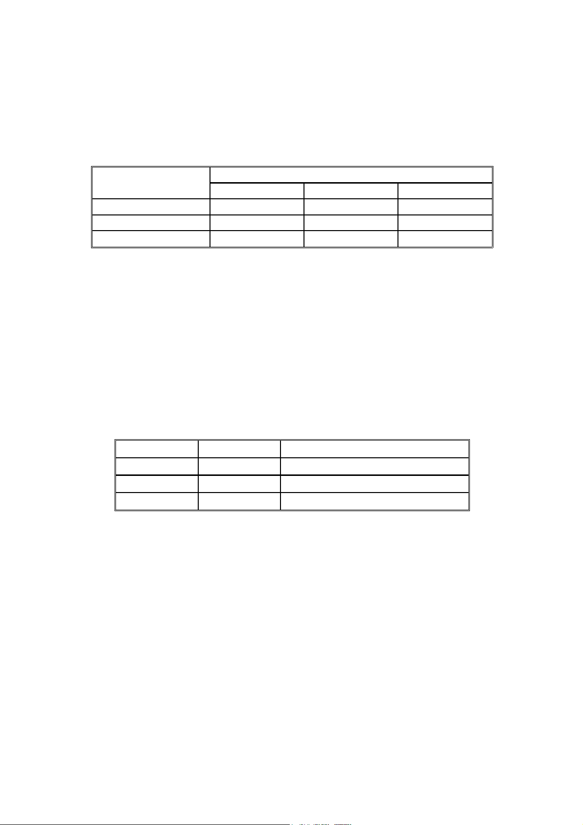
LEGEND
PRODUCT CODE COMPANY
GESTETNER RICOH SAVIN
A166 2703 Aficio 2003 SDC103
A187 2703D Aficio 2103 SDC103A
A189 2703DE Aficio 2203 SDC103E
DOCUMENTATION HISTORY
REV. NO. DATE COMMENTS
*
10/96 Original Prin ti n g
Page 11

Page 12

Table of Contents
OVERALL MACHINE INFORMATION
1. SPECIFICA TIONS . . . . . . . . . . . . . . . . . . . . . . . . . . . . . . . . . . . . . . 1-1
1.1 MACHINE CONFIGURATION. . . . . . . . . . . . . . . . . . . . . . . . . . . . . . . . . . . . . 1-1
1.2 GENERAL SPECIFICATIONS. . . . . . . . . . . . . . . . . . . . . . . . . . . . . . . . . . . . . 1-2
1.3 DETECTABLE ORIGINAL SIZE BY PLATEN/ARDF . . . . . . . . . . . . . . . . . . . 1-6
1.4 COPY PAPER SIZE . . . . . . . . . . . . . . . . . . . . . . . . . . . . . . . . . . . . . . . . . . . . 1-7
1.5 PAPER SIZES AVAILABLE WITH APS . . . . . . . . . . . . . . . . . . . . . . . . . . . . . 1-8
1.6 NOISE EMISSION. . . . . . . . . . . . . . . . . . . . . . . . . . . . . . . . . . . . . . . . . . . . . . 1-9
1.7 POWER CONSUMPTION . . . . . . . . . . . . . . . . . . . . . . . . . . . . . . . . . . . . . . . 1-10
1.8 DISPLAY EDITOR SPECIFICATION . . . . . . . . . . . . . . . . . . . . . . . . . . . . . . 1-10
2. MACHINE CONFIGURATION . . . . . . . . . . . . . . . . . . . . . . . . . . . 1-11
2.1 COPY PROCESSES AROUND THE DRUM AND BELT . . . . . . . . . . . . . . . 1-11
3. MAJOR UNIT OVERVIEW . . . . . . . . . . . . . . . . . . . . . . . . . . . . . . 1-13
4. PARTS LAYOUT . . . . . . . . . . . . . . . . . . . . . . . . . . . . . . . . . . . . . . 1-16
4.1 MECHANICAL COMPONENT LAYOUT . . . . . . . . . . . . . . . . . . . . . . . . . . 1-16
4.2 PCB (A166/A187 COPIERS) . . . . . . . . . . . . . . . . . . . . . . . . . . . . . . . . . . . . 1-17
4.3 PCB (A189 COPIER) . . . . . . . . . . . . . . . . . . . . . . . . . . . . . . . . . . . . . . . . . . 1-18
4.4 SOLENOIDS AND CLUTCHES . . . . . . . . . . . . . . . . . . . . . . . . . . . . . . . . . . 1-19
4.5 SWITCHES AND HEATERS . . . . . . . . . . . . . . . . . . . . . . . . . . . . . . . . . . . . 1-20
4.6 SENSORS . . . . . . . . . . . . . . . . . . . . . . . . . . . . . . . . . . . . . . . . . . . . . . . . . . 1-21
4.7 MOTORS . . . . . . . . . . . . . . . . . . . . . . . . . . . . . . . . . . . . . . . . . . . . . . . . . . . 1-22
4.8 DRIVE LAYOUT . . . . . . . . . . . . . . . . . . . . . . . . . . . . . . . . . . . . . . . . . . . . . 1-23
4.9 FANS AND AIR FLOW . . . . . . . . . . . . . . . . . . . . . . . . . . . . . . . . . . . . . . . . 1-24
4.10 COUNTERS (A166/A187 COPIERS) . . . . . . . . . . . . . . . . . . . . . . . . . . . . 1-25
4.11 COUNTER (A189 COPIER) . . . . . . . . . . . . . . . . . . . . . . . . . . . . . . . . . . . 1-26
5. ELECTRICAL COMPONENT LIST . . . . . . . . . . . . . . . . . . . . . . . . 1-27
5.1 PRINTED CIRCUIT BOARDS. . . . . . . . . . . . . . . . . . . . . . . . . . . . . . . . . . . . 1-27
5.2 SOLENOIDS . . . . . . . . . . . . . . . . . . . . . . . . . . . . . . . . . . . . . . . . . . . . . . . . . 1-28
5.3 CLUTCHES . . . . . . . . . . . . . . . . . . . . . . . . . . . . . . . . . . . . . . . . . . . . . . . . . . 1-28
SM i A166/A187/A189
Page 13

5.4 SWITCHES . . . . . . . . . . . . . . . . . . . . . . . . . . . . . . . . . . . . . . . . . . . . . . . . . . 1-29
5.5 LAMPS. . . . . . . . . . . . . . . . . . . . . . . . . . . . . . . . . . . . . . . . . . . . . . . . . . . . . . 1-29
5.6 HEATERS . . . . . . . . . . . . . . . . . . . . . . . . . . . . . . . . . . . . . . . . . . . . . . . . . . . 1-30
5.7 THERMISTORS. . . . . . . . . . . . . . . . . . . . . . . . . . . . . . . . . . . . . . . . . . . . . . . 1-30
5.8 THERMOFUSES . . . . . . . . . . . . . . . . . . . . . . . . . . . . . . . . . . . . . . . . . . . . . . 1-30
5.9 THERMOSTAT . . . . . . . . . . . . . . . . . . . . . . . . . . . . . . . . . . . . . . . . . . . . . . . 1-30
5.10 SENSORS . . . . . . . . . . . . . . . . . . . . . . . . . . . . . . . . . . . . . . . . . . . . . . . . . . 1-31
5.11 MOTORS. . . . . . . . . . . . . . . . . . . . . . . . . . . . . . . . . . . . . . . . . . . . . . . . . . . 1-32
5.12 FAN MOTORS. . . . . . . . . . . . . . . . . . . . . . . . . . . . . . . . . . . . . . . . . . . . . . . 1-32
5.13 COUNTER. . . . . . . . . . . . . . . . . . . . . . . . . . . . . . . . . . . . . . . . . . . . . . . . . . 1-33
DETAILED DESCRIPTIONS
1. PROCESS CONTROL . . . . . . . . . . . . . . . . . . . . . . . . . . . . . . . . . . . 2-1
1.1 OVERVIEW . . . . . . . . . . . . . . . . . . . . . . . . . . . . . . . . . . . . . . . . . . . . . . . . . . 2-1
1.2 PROCESS CONTROL MEASUREMENT TIMING . . . . . . . . . . . . . . . . . . . . . 2-3
1.3 POTENTIAL CONTROL (LATENT IMAGE CONTROL) . . . . . . . . . . . . . . . . . 2-4
1.3.1 Concept . . . . . . . . . . . . . . . . . . . . . . . . . . . . . . . . . . . . . . . . . . . . . . . . . . 2-4
1.3.2 Process Control Self Check. . . . . . . . . . . . . . . . . . . . . . . . . . . . . . . . . . . 2-5
1.3.3 Process Control Self Check Procedure . . . . . . . . . . . . . . . . . . . . . . . . . 2-6
1.3.4 Drum Potential Sensor Calibration . . . . . . . . . . . . . . . . . . . . . . . . . . . . . 2-7
1.3.5 Vsg Calibration. . . . . . . . . . . . . . . . . . . . . . . . . . . . . . . . . . . . . . . . . . . . . 2-8
1.3.6 Writing the Gradation Pattern . . . . . . . . . . . . . . . . . . . . . . . . . . . . . . . . . 2-8
1.3.7 Gradation Pattern Potential Detection . . . . . . . . . . . . . . . . . . . . . . . . . . . 2-8
1.3.8 Gradation Pattern Development . . . . . . . . . . . . . . . . . . . . . . . . . . . . . . . 2-9
1.3.9 Gradation Pattern Density Detection . . . . . . . . . . . . . . . . . . . . . . . . . . . . 2-9
1.3.10 Development Potential Calculation . . . . . . . . . . . . . . . . . . . . . . . . . . . . 2-9
1.3.11 V
1.3.12 V
1.3.13 Confirmation Procedure . . . . . . . . . . . . . . . . . . . . . . . . . . . . . . . . . . . 2-10
, VB, VL Selection (Pointer Table) . . . . . . . . . . . . . . . . . . . . . . . . . . 2-10
D
, VB, ILD Correction . . . . . . . . . . . . . . . . . . . . . . . . . . . . . . . . . . . . . 2-10
G
1.3.14 Potential Control in Abnormal Sensor Conditions . . . . . . . . . . . . . . . . 2-11
1.3.15 Abnormal Sensor Conditions (SC). . . . . . . . . . . . . . . . . . . . . . . . . . . . 2-14
A166/A187/A189 ii SM
Page 14

1.4 TONER SUPPLY CONTROL . . . . . . . . . . . . . . . . . . . . . . . . . . . . . . . . . . . . 2-15
1.4.1 Toner Supply Control Method . . . . . . . . . . . . . . . . . . . . . . . . . . . . . . . . 2-15
1.4.2 Fuzzy Control Mode . . . . . . . . . . . . . . . . . . . . . . . . . . . . . . . . . . . . . . . 2-15
1.4.3 Fixed Supply Mode . . . . . . . . . . . . . . . . . . . . . . . . . . . . . . . . . . . . . . . . 2-17
1.4.4 Toner Supply in Abnormal Sensor Conditions. . . . . . . . . . . . . . . . . . . . 2-17
1.4.5 Toner End Detection . . . . . . . . . . . . . . . . . . . . . . . . . . . . . . . . . . . . . . . 2-18
1.4.6 Developer Agitation . . . . . . . . . . . . . . . . . . . . . . . . . . . . . . . . . . . . . . . . 2-20
2. DRUM UNIT . . . . . . . . . . . . . . . . . . . . . . . . . . . . . . . . . . . . . . . . . 2-24
2.1 OVERVIEW . . . . . . . . . . . . . . . . . . . . . . . . . . . . . . . . . . . . . . . . . . . . . . . . . . 2-24
2.1.1 OPC Drum Characteristics. . . . . . . . . . . . . . . . . . . . . . . . . . . . . . . . . . . 2-24
2.2 MECHANISMS . . . . . . . . . . . . . . . . . . . . . . . . . . . . . . . . . . . . . . . . . . . . . . 2-25
2.2.1 Drive Mechanism . . . . . . . . . . . . . . . . . . . . . . . . . . . . . . . . . . . . . . . . . . 2-25
2.2.2 Drum Charge . . . . . . . . . . . . . . . . . . . . . . . . . . . . . . . . . . . . . . . . . . . . 2-26
2.2.3 Drum Cleaning . . . . . . . . . . . . . . . . . . . . . . . . . . . . . . . . . . . . . . . . . . . 2-27
2.2.4 Quenching . . . . . . . . . . . . . . . . . . . . . . . . . . . . . . . . . . . . . . . . . . . . . . . 2-28
3. SCANNER UNIT . . . . . . . . . . . . . . . . . . . . . . . . . . . . . . . . . . . . . . 2-29
3.1 OVERVIEW . . . . . . . . . . . . . . . . . . . . . . . . . . . . . . . . . . . . . . . . . . . . . . . . . . 2-29
3.2 SCANNER . . . . . . . . . . . . . . . . . . . . . . . . . . . . . . . . . . . . . . . . . . . . . . . . . . 2-30
3.3 SCANNER DRIVE . . . . . . . . . . . . . . . . . . . . . . . . . . . . . . . . . . . . . . . . . . . . 2-31
3.4 COLOR CCD . . . . . . . . . . . . . . . . . . . . . . . . . . . . . . . . . . . . . . . . . . . . . . . . 2-32
3.5 WHITE PLATE SCANNING . . . . . . . . . . . . . . . . . . . . . . . . . . . . . . . . . . . . . 2-33
3.6 SCANNER IPU BOARD . . . . . . . . . . . . . . . . . . . . . . . . . . . . . . . . . . . . . . . . 2-33
3.7 ORIGINAL SIZE DETECTION . . . . . . . . . . . . . . . . . . . . . . . . . . . . . . . . . . . 2-34
3.8 OTHERS . . . . . . . . . . . . . . . . . . . . . . . . . . . . . . . . . . . . . . . . . . . . . . . . . . . . 2-36
4. IMAGE PROCESSING. . . . . . . . . . . . . . . . . . . . . . . . . . . . . . . . . . 2-38
4.1 OVERVIEW . . . . . . . . . . . . . . . . . . . . . . . . . . . . . . . . . . . . . . . . . . . . . . . . . . 2-38
4.2 SCANNER SECTION BLOCK DIAGRAM . . . . . . . . . . . . . . . . . . . . . . . . . . . 2-39
4.3 SCANNER SECTION . . . . . . . . . . . . . . . . . . . . . . . . . . . . . . . . . . . . . . . . . . 2-40
4.3.1 Photoelectric Conversion. . . . . . . . . . . . . . . . . . . . . . . . . . . . . . . . . . . . 2-40
4.3.2 Signal Processing . . . . . . . . . . . . . . . . . . . . . . . . . . . . . . . . . . . . . . . . . 2-40
4.3.3 A/D Conversion . . . . . . . . . . . . . . . . . . . . . . . . . . . . . . . . . . . . . . . . . . . 2-40
4.3.4 Shading Circuit . . . . . . . . . . . . . . . . . . . . . . . . . . . . . . . . . . . . . . . . . . . 2-41
SM iii A166/A187/A189
Page 15

4.3.5 D/A Conversion . . . . . . . . . . . . . . . . . . . . . . . . . . . . . . . . . . . . . . . . . . . 2-43
4.3.6 Scan Line Correction . . . . . . . . . . . . . . . . . . . . . . . . . . . . . . . . . . . . . . . 2-43
4.4 IPU SECTION BLOCK DIAGRAM. . . . . . . . . . . . . . . . . . . . . . . . . . . . . . . . . 2-44
4.5 IPU SECTION . . . . . . . . . . . . . . . . . . . . . . . . . . . . . . . . . . . . . . . . . . . . . . . . 2-45
4.5.1 Picture Element Correction and Scanner Gamma Correction . . . . . . . . 2-45
4.5.2 ACS (Auto Color Selection) . . . . . . . . . . . . . . . . . . . . . . . . . . . . . . . . . 2-47
4.5.3 Auto Letter/Photo Separation. . . . . . . . . . . . . . . . . . . . . . . . . . . . . . . . . 2-48
4.5.4 Filtering and Color Conversion. . . . . . . . . . . . . . . . . . . . . . . . . . . . . . . . 2-50
4.5.5 Main Scan Magnification . . . . . . . . . . . . . . . . . . . . . . . . . . . . . . . . . . . . 2-57
4.5.6 Gamma Correction (Printer Gamma) . . . . . . . . . . . . . . . . . . . . . . . . . . 2-58
4.5.7 Gradation Treatment (Dither Processing) . . . . . . . . . . . . . . . . . . . . . . . 2-61
4.6 CPU . . . . . . . . . . . . . . . . . . . . . . . . . . . . . . . . . . . . . . . . . . . . . . . . . . . . . . . . 2-62
4.7 EXTENDED IPU (EDIT MACHINE ONLY) . . . . . . . . . . . . . . . . . . . . . . . . . . 2-62
4.8 OTHERS . . . . . . . . . . . . . . . . . . . . . . . . . . . . . . . . . . . . . . . . . . . . . . . . . . . . 2-64
4.8.1 Interface. . . . . . . . . . . . . . . . . . . . . . . . . . . . . . . . . . . . . . . . . . . . . . . . . 2-64
4.8.2 IPU Board Test . . . . . . . . . . . . . . . . . . . . . . . . . . . . . . . . . . . . . . . . . . . 2-64
5. LASER EXPOSURE . . . . . . . . . . . . . . . . . . . . . . . . . . . . . . . . . . . 2-65
5.1 OVERVIEW . . . . . . . . . . . . . . . . . . . . . . . . . . . . . . . . . . . . . . . . . . . . . . . . . . 2-65
5.2 OPTICAL PATH . . . . . . . . . . . . . . . . . . . . . . . . . . . . . . . . . . . . . . . . . . . . . . 2-66
5.2.1 Overview . . . . . . . . . . . . . . . . . . . . . . . . . . . . . . . . . . . . . . . . . . . . . . . . 2-66
5.2.2 Cylindrical Lens . . . . . . . . . . . . . . . . . . . . . . . . . . . . . . . . . . . . . . . . . . . 2-67
5.2.3 Polygon Mirror . . . . . . . . . . . . . . . . . . . . . . . . . . . . . . . . . . . . . . . . . . . . 2-67
5.2.4 F-theta Lenses and the BTL
5.2.5 Laser Synchronizing Detector Boards . . . . . . . . . . . . . . . . . . . . . . . . . 2-69
5.3 GRADATION CONTROL (LASER POWER MODULATION) . . . . . . . . . . . 2-70
5.4 AUTO POWER CONTROL (APC) . . . . . . . . . . . . . . . . . . . . . . . . . . . . . . . . 2-71
5.5 LD SAFETY SWITCHES . . . . . . . . . . . . . . . . . . . . . . . . . . . . . . . . . . . . . . . 2-72
. . . . . . . . . . . . . . . . . . . . . . . . . . . . . . . . 2-68
6. DEVELOPMENT UNIT. . . . . . . . . . . . . . . . . . . . . . . . . . . . . . . . . . 2-73
6.1 OVERVIEW . . . . . . . . . . . . . . . . . . . . . . . . . . . . . . . . . . . . . . . . . . . . . . . . . . 2-73
6.2 MECHANISMS . . . . . . . . . . . . . . . . . . . . . . . . . . . . . . . . . . . . . . . . . . . . . . . 2-74
6.2.1 Revolver Development Mechanism . . . . . . . . . . . . . . . . . . . . . . . . . . . . 2-74
A166/A187/A189 iv SM
Page 16

6.2.2 Development Mechanism . . . . . . . . . . . . . . . . . . . . . . . . . . . . . . . . . . . 2-77
6.2.3 Toner Mixing . . . . . . . . . . . . . . . . . . . . . . . . . . . . . . . . . . . . . . . . . . . . . 2-78
6.2.4 Developer Mixing . . . . . . . . . . . . . . . . . . . . . . . . . . . . . . . . . . . . . . . . . 2-81
6.2.5 Development Roller Drive . . . . . . . . . . . . . . . . . . . . . . . . . . . . . . . . . . . 2-84
6.2.6 Development Bias . . . . . . . . . . . . . . . . . . . . . . . . . . . . . . . . . . . . . . . . . 2-85
6.2.7 Toner Cartridge Detection . . . . . . . . . . . . . . . . . . . . . . . . . . . . . . . . . . 2-86
6.2.8 Color Toner Positioning Pin . . . . . . . . . . . . . . . . . . . . . . . . . . . . . . . . . 2-87
6.2.9 Revolver Positioning . . . . . . . . . . . . . . . . . . . . . . . . . . . . . . . . . . . . . . . 2-88
7. TRANSFER BELT UNIT . . . . . . . . . . . . . . . . . . . . . . . . . . . . . . . . 2 -93
7.1 OVERVIEW . . . . . . . . . . . . . . . . . . . . . . . . . . . . . . . . . . . . . . . . . . . . . . . . . . 2-93
7.2 LAYOUT . . . . . . . . . . . . . . . . . . . . . . . . . . . . . . . . . . . . . . . . . . . . . . . . . . . 2-94
7.3 BELT TRANSFER . . . . . . . . . . . . . . . . . . . . . . . . . . . . . . . . . . . . . . . . . . . . . 2-95
7.3.1 Transfer Belt Drive . . . . . . . . . . . . . . . . . . . . . . . . . . . . . . . . . . . . . . . . 2-95
7.3.2 Transfer Belt Release Mechanism . . . . . . . . . . . . . . . . . . . . . . . . . . . 2-101
7.3.3 Belt Transfer Bias . . . . . . . . . . . . . . . . . . . . . . . . . . . . . . . . . . . . . . . 2-102
7.3.4 Belt Mark Detection . . . . . . . . . . . . . . . . . . . . . . . . . . . . . . . . . . . . . . . 2-103
7.3.5 Transfer Belt Cleaning . . . . . . . . . . . . . . . . . . . . . . . . . . . . . . . . . . . . 2-104
7.3.6 Toner Collection . . . . . . . . . . . . . . . . . . . . . . . . . . . . . . . . . . . . . . . . . 2-105
7.3.7 Belt Lubricant Mechanism . . . . . . . . . . . . . . . . . . . . . . . . . . . . . . . . . 2-106
7.3.8 PTL (Pre-transfer Lamp) . . . . . . . . . . . . . . . . . . . . . . . . . . . . . . . . . . . 2-107
7.4 PAPER TRANSFER . . . . . . . . . . . . . . . . . . . . . . . . . . . . . . . . . . . . . . . . . 2-108
7.4.1 Paper Transfer Bias. . . . . . . . . . . . . . . . . . . . . . . . . . . . . . . . . . . . . . . 2-108
7.4.2 Paper Discharge . . . . . . . . . . . . . . . . . . . . . . . . . . . . . . . . . . . . . . . . . 2-110
7.4.3 Uniform Transfer Belt Charge . . . . . . . . . . . . . . . . . . . . . . . . . . . . . . . 2-110
8. PAPER FEED AND REGISTRATION . . . . . . . . . . . . . . . . . . . . 2-111
8.1 OVERVIEW . . . . . . . . . . . . . . . . . . . . . . . . . . . . . . . . . . . . . . . . . . . . . . . . . 2-111
8.2 PAPER TRAY MECHANISM (A166 COPIER ONLY) . . . . . . . . . . . . . . . . 2-112
8.2.1 Paper Feed Drive Mechanism . . . . . . . . . . . . . . . . . . . . . . . . . . . . . . . 2-112
8.2.2 Paper Lift Mechanism . . . . . . . . . . . . . . . . . . . . . . . . . . . . . . . . . . . . 2-114
8.2.3 Paper End Detection . . . . . . . . . . . . . . . . . . . . . . . . . . . . . . . . . . . . . . 2-115
8.2.4 Paper Size Detection . . . . . . . . . . . . . . . . . . . . . . . . . . . . . . . . . . . . 2-116
8.2.5 Vertical Transport Mechanism . . . . . . . . . . . . . . . . . . . . . . . . . . . . . . 2-117
SM v A166/A187/A189
Page 17

8.2.6 Side Fence Double-stopper Mechanism . . . . . . . . . . . . . . . . . . . . . . . 2-118
8.3 BY-PASS FEED. . . . . . . . . . . . . . . . . . . . . . . . . . . . . . . . . . . . . . . . . . . . . . 2-119
8.3.1 By-pass Feed Table Mechanism . . . . . . . . . . . . . . . . . . . . . . . . . . . . 2-119
8.3.2 Paper Feed . . . . . . . . . . . . . . . . . . . . . . . . . . . . . . . . . . . . . . . . . . . . . 2-120
8.3.3 Paper End Detection . . . . . . . . . . . . . . . . . . . . . . . . . . . . . . . . . . . . . . 2-120
8.3.4 By-pass Feed Paper Width Detection . . . . . . . . . . . . . . . . . . . . . . . . 2-121
8.3.5 Pick-up Roller Pressure Mechanism . . . . . . . . . . . . . . . . . . . . . . . . . . 2-122
8.4 REGISTRATION DRIVE MECHANISM . . . . . . . . . . . . . . . . . . . . . . . . . . . 2-123
9. PAPER TRANSPORT AND IMAGE FUSING. . . . . . . . . . . . . . . 2-1 24
9.1 PAPER TRANSPORT UNIT . . . . . . . . . . . . . . . . . . . . . . . . . . . . . . . . . . . 2-124
9.1.1 Drive Mechanism . . . . . . . . . . . . . . . . . . . . . . . . . . . . . . . . . . . . . . . . . 2-124
9.1.2 Transport Mechanism . . . . . . . . . . . . . . . . . . . . . . . . . . . . . . . . . . . . . 2-124
9.2 FUSING UNIT OVERVIEW . . . . . . . . . . . . . . . . . . . . . . . . . . . . . . . . . . . . 2-125
9.3 FUSING UNIT . . . . . . . . . . . . . . . . . . . . . . . . . . . . . . . . . . . . . . . . . . . . . . . 2-126
9.3.1 Fusing Temperature Control . . . . . . . . . . . . . . . . . . . . . . . . . . . . . . . . 2-126
9.3.2 Fusing Pressure Mechanism . . . . . . . . . . . . . . . . . . . . . . . . . . . . . . . 2-127
9.3.3 Oil Supply Mechanism . . . . . . . . . . . . . . . . . . . . . . . . . . . . . . . . . . . . 2-128
9.3.4 Cleaning Mechanism . . . . . . . . . . . . . . . . . . . . . . . . . . . . . . . . . . . . . . 2-129
9.3.5 Fusing Drive Release Mechanism . . . . . . . . . . . . . . . . . . . . . . . . . . . 2-130
9.4 JUNCTION GATE AND PAPER EXIT . . . . . . . . . . . . . . . . . . . . . . . . . . . . 2-131
9.4.1 Paper Exit . . . . . . . . . . . . . . . . . . . . . . . . . . . . . . . . . . . . . . . . . . . . . . 2-131
9.4.2 Junction Gate Mechanism (A187/A189 copiers only) . . . . . . . . . . . . 2-132
9.4.3 Paper Exit Door (A187/A189 copiers only) . . . . . . . . . . . . . . . . . . . . . 2-133
10. DUPLEX UNIT . . . . . . . . . . . . . . . . . . . . . . . . . . . . . . . . . . . . . 2-134
10.1 OVERVIEW . . . . . . . . . . . . . . . . . . . . . . . . . . . . . . . . . . . . . . . . . . . . . . . . 2-134
10.2 DUPLEX UNIT MECHANISMS (A187/A189 copiers only) . . . . . . . . . . . . 2-135
10.2.1 Drive Mechanism . . . . . . . . . . . . . . . . . . . . . . . . . . . . . . . . . . . . . . . . 2-135
10.2.2 Duplex Paper Path . . . . . . . . . . . . . . . . . . . . . . . . . . . . . . . . . . . . . . 2-136
10.2.3 Duplex Entrance To Duplex Tray . . . . . . . . . . . . . . . . . . . . . . . . . . 2-137
10.2.4 Jogger Mechanism . . . . . . . . . . . . . . . . . . . . . . . . . . . . . . . . . . . . . 2-138
10.2.5 Paper Feed from the Duplex Tray . . . . . . . . . . . . . . . . . . . . . . . . . . 2-139
10.2.6 Paper Feed System . . . . . . . . . . . . . . . . . . . . . . . . . . . . . . . . . . . . . 2-140
A166/A187/A189 vi SM
Page 18

11. SYSTEM CONFIGURATION . . . . . . . . . . . . . . . . . . . . . . . . . . 2-141
11.1 BLOCK DIAGRAM. . . . . . . . . . . . . . . . . . . . . . . . . . . . . . . . . . . . . . . . . . . 2-141
11.2 COMMAND SEQUENCE . . . . . . . . . . . . . . . . . . . . . . . . . . . . . . . . . . . . . 2-142
11.2.1 Normal Copy Mode . . . . . . . . . . . . . . . . . . . . . . . . . . . . . . . . . . . . . . 2-142
11.2.2 Edit Mode. . . . . . . . . . . . . . . . . . . . . . . . . . . . . . . . . . . . . . . . . . . . . . 2-143
INSTALLATION
1. INSTALLATION REQUIREMENTS . . . . . . . . . . . . . . . . . . . . . . . . 3-1
1.1 DIMENSIONS . . . . . . . . . . . . . . . . . . . . . . . . . . . . . . . . . . . . . . . . . . . . . . . . . 3-1
1.2 ENVIRONMENT . . . . . . . . . . . . . . . . . . . . . . . . . . . . . . . . . . . . . . . . . . . . . . . 3-2
1.2.1 Environmental Requirements. . . . . . . . . . . . . . . . . . . . . . . . . . . . . . . . . . 3-2
1.2.2 Minimum Space Requirements . . . . . . . . . . . . . . . . . . . . . . . . . . . . . . . 3-4
1.2.3 Power Requirements . . . . . . . . . . . . . . . . . . . . . . . . . . . . . . . . . . . . . . . . 3-5
2. COPIER INSTALLATION . . . . . . . . . . . . . . . . . . . . . . . . . . . . . . . . 3-6
2.1 ACCESSORY CHECK. . . . . . . . . . . . . . . . . . . . . . . . . . . . . . . . . . . . . . . . . . . 3-6
2.2 COPIER INSTALLATION PROCEDURE . . . . . . . . . . . . . . . . . . . . . . . . . . . . 3-7
3. INSTALLATION PROCEDURE FLOWCHART . . . . . . . . . . . . . . 3-36
4. PAPER TRAY UNIT (A549/A550) INSTALLATION . . . . . . . . . . . 3-40
4.1 ACCESSORY CHECK. . . . . . . . . . . . . . . . . . . . . . . . . . . . . . . . . . . . . . . . . . 3-40
4.2 INSTALLATION PROCEDURE. . . . . . . . . . . . . . . . . . . . . . . . . . . . . . . . . . . 3-41
4.3 TRAY HEATER (OPTION) . . . . . . . . . . . . . . . . . . . . . . . . . . . . . . . . . . . . . . 3-43
5. ARDF (A548) INSTALLATION . . . . . . . . . . . . . . . . . . . . . . . . . . . 3-44
5.1 ACCESSORY CHECK. . . . . . . . . . . . . . . . . . . . . . . . . . . . . . . . . . . . . . . . . . 3-44
5.2 INSTALLATION PROCEDURE. . . . . . . . . . . . . . . . . . . . . . . . . . . . . . . . . . . 3-45
6. 10-BIN SORTER (A555) INSTALLATION . . . . . . . . . . . . . . . . . . 3-46
6.1 ACCESSORY CHECK. . . . . . . . . . . . . . . . . . . . . . . . . . . . . . . . . . . . . . . . . . 3-46
INSTALLATION PROCEDURE
6.2
. . . . . . . . . . . . . . . . . . . . . . . . . . . . . . . . . . 3-47
7. FILM PROJECTOR TABLE (A579) INSTALLATION. . . . . . . . . . 3-51
8. FILM PROJECTOR UNIT (A718) INSTALLATION . . . . . . . . . . . 3-53
8.1 ACCESSORY CHECK. . . . . . . . . . . . . . . . . . . . . . . . . . . . . . . . . . . . . . . . . . 3-53
SM vii A166/A187/A189
Page 19

8.2 INSTALLATION PROCEDURE. . . . . . . . . . . . . . . . . . . . . . . . . . . . . . . . . . . 3-54
9. OTHERS . . . . . . . . . . . . . . . . . . . . . . . . . . . . . . . . . . . . . . . . . . . . 3-61
9.1 KEY COUNTER. . . . . . . . . . . . . . . . . . . . . . . . . . . . . . . . . . . . . . . . . . . . . . . 3-61
9.1.1 Key Counter Installation. . . . . . . . . . . . . . . . . . . . . . . . . . . . . . . . . . . . . 3-61
9.1.2 Setting up the SP Modes for the Key Counter. . . . . . . . . . . . . . . . . . . . 3-62
9.2 MOUNTING THE PACKING RETAINERS FOR MOVING THE COPIER . . 3-63
SERVICE TABLES
1. SERVICE PROGRAM MODES . . . . . . . . . . . . . . . . . . . . . . . . . . . . 4-1
1.1 SP TABLE . . . . . . . . . . . . . . . . . . . . . . . . . . . . . . . . . . . . . . . . . . . . . . . . . . . . 4-1
1.2 SERVICE PROGRAM MODE OPERATION . . . . . . . . . . . . . . . . . . . . . . . . . . 4-1
1.2.1 LCD Display. . . . . . . . . . . . . . . . . . . . . . . . . . . . . . . . . . . . . . . . . . . . . . . 4-1
1.3 SP MODE ADDITIONAL NOTES . . . . . . . . . . . . . . . . . . . . . . . . . . . . . . . . . . 4-2
1.3.1 SP 3-973 Process Control Interval Self Check . . . . . . . . . . . . . . . . . . . . 4-2
1.3.2 SP4-301 APS Data Confirmation. . . . . . . . . . . . . . . . . . . . . . . . . . . . . . . 4-2
1.3.3 SP5-501 PM Counter. . . . . . . . . . . . . . . . . . . . . . . . . . . . . . . . . . . . . . . . 4-2
1.3.4 SP5-802-1 Printer Free Run . . . . . . . . . . . . . . . . . . . . . . . . . . . . . . . . . . 4-2
1.3.5 SP5-802-4 System Free Run. . . . . . . . . . . . . . . . . . . . . . . . . . . . . . . . . . 4-4
1.3.6 SP5-803 Input Check. . . . . . . . . . . . . . . . . . . . . . . . . . . . . . . . . . . . . . . . 4-4
1.3.7 SP5-804 Output Check . . . . . . . . . . . . . . . . . . . . . . . . . . . . . . . . . . . . . . 4-7
1.3.8 SP5-955 Printer Test Pattern. . . . . . . . . . . . . . . . . . . . . . . . . . . . . . . . . . 4-9
1.3.9 SP5-974 Auto Memory Call . . . . . . . . . . . . . . . . . . . . . . . . . . . . . . . . . . . 4-9
1.3.10 SP6-102 Sort/Stack Limitation. . . . . . . . . . . . . . . . . . . . . . . . . . . . . . . . 4-9
1.3.11 SP6-107 Sorter Free Run . . . . . . . . . . . . . . . . . . . . . . . . . . . . . . . . . . 4-10
1.3.12 SP6-901 Optional Paper Bank Input Check. . . . . . . . . . . . . . . . . . . . . 4-10
1.3.13 SP6-902 Output Check for the Optional Paper Bank Unit . . . . . . . . . . 4-12
1.3.14 SP6-903 Sorter Input Check . . . . . . . . . . . . . . . . . . . . . . . . . . . . . . . . 4-13
1.3.15 SP6-904 Sorter Output Check . . . . . . . . . . . . . . . . . . . . . . . . . . . . . . 4-13
1.3.16 SP7-507-1 Paper Jam (Last 10) . . . . . . . . . . . . . . . . . . . . . . . . . . . . . 4-14
1.3.17 SP7-507-2 Original Jam (Last 10) . . . . . . . . . . . . . . . . . . . . . . . . . . . . 4-16
2. USER PROGRAM MODES . . . . . . . . . . . . . . . . . . . . . . . . . . . . . . 4-17
A166/A187/A189 viii SM
Page 20

2.1 USER PROGRAM MODE OPERATION . . . . . . . . . . . . . . . . . . . . . . . . . . . . 4-17
2.2 UP MODE TABLE . . . . . . . . . . . . . . . . . . . . . . . . . . . . . . . . . . . . . . . . . . . . . 4-18
3. TP/FUSE/LED/SW . . . . . . . . . . . . . . . . . . . . . . . . . . . . . . . . . . . . . 4-30
3.1 TEST POINT . . . . . . . . . . . . . . . . . . . . . . . . . . . . . . . . . . . . . . . . . . . . . . . . . 4-30
3.2 FUSE CONDITIONS . . . . . . . . . . . . . . . . . . . . . . . . . . . . . . . . . . . . . . . . . . . 4-34
3.3 LED CONDITIONS . . . . . . . . . . . . . . . . . . . . . . . . . . . . . . . . . . . . . . . . . . . . 4-34
3.4 SWITCHES . . . . . . . . . . . . . . . . . . . . . . . . . . . . . . . . . . . . . . . . . . . . . . . . . . 4-35
4. REGULAR PM TABLE . . . . . . . . . . . . . . . . . . . . . . . . . . . . . . . . . 4-36
5. SP MODES USED AFTER REPLACEMENT
AND CLEANING . . . . . . . . . . . . . . . . . . . . . . . . . . . . . . . . . . . . . . 4-43
6. REGULAR PM PROCEDURE. . . . . . . . . . . . . . . . . . . . . . . . . . . . 4-45
REPLACEMENT AND ADJUSTMENT
1. EXTERIOR. . . . . . . . . . . . . . . . . . . . . . . . . . . . . . . . . . . . . . . . . . . . 5-1
1.1 PLATEN COVER . . . . . . . . . . . . . . . . . . . . . . . . . . . . . . . . . . . . . . . . . . . . . . 5-1
1.2 FRONT COVER . . . . . . . . . . . . . . . . . . . . . . . . . . . . . . . . . . . . . . . . . . . . . . . 5-1
1.3 REAR COVER . . . . . . . . . . . . . . . . . . . . . . . . . . . . . . . . . . . . . . . . . . . . . . . . 5-2
1.4 EXPOSURE GLASS . . . . . . . . . . . . . . . . . . . . . . . . . . . . . . . . . . . . . . . . . . . . 5-2
1.5 UPPER COVERS . . . . . . . . . . . . . . . . . . . . . . . . . . . . . . . . . . . . . . . . . . . . . . 5-3
1.6 OPERATION PANEL. . . . . . . . . . . . . . . . . . . . . . . . . . . . . . . . . . . . . . . . . . . . 5-4
1.6.1 A166/A187 Copiers . . . . . . . . . . . . . . . . . . . . . . . . . . . . . . . . . . . . . . . . . 5-4
1.6.2 A189 Copier . . . . . . . . . . . . . . . . . . . . . . . . . . . . . . . . . . . . . . . . . . . . . . 5-4
1.7 RIGHT COVERS . . . . . . . . . . . . . . . . . . . . . . . . . . . . . . . . . . . . . . . . . . . . . . 5-5
1.8 LEFT COVERS . . . . . . . . . . . . . . . . . . . . . . . . . . . . . . . . . . . . . . . . . . . . . . . . 5-5
1.9 INNER COVERS . . . . . . . . . . . . . . . . . . . . . . . . . . . . . . . . . . . . . . . . . . . . . . 5-6
1.10 USED TONER TANK . . . . . . . . . . . . . . . . . . . . . . . . . . . . . . . . . . . . . . . . . . 5-6
1.11 LIFTING THE SCANNER UNIT. . . . . . . . . . . . . . . . . . . . . . . . . . . . . . . . . . . 5-7
2. DRUM UNIT . . . . . . . . . . . . . . . . . . . . . . . . . . . . . . . . . . . . . . . . . . 5-8
2.1 DRUM REPLACEMENT . . . . . . . . . . . . . . . . . . . . . . . . . . . . . . . . . . . . . . . . . 5-8
2.2 CLEANING BLADE REPLACEMENT . . . . . . . . . . . . . . . . . . . . . . . . . . . . . 5-10
2.3 CLEANING BRUSH REPLACEMENT . . . . . . . . . . . . . . . . . . . . . . . . . . . . . 5-11
SM ix A166/A187/A189
Page 21

2.4 LUBRICANT BAR REPLACEMENT . . . . . . . . . . . . . . . . . . . . . . . . . . . . . . 5-12
2.5 CHARGE GRID AND CORONA WIRE REPLACEMENT . . . . . . . . . . . . . . 5-13
3. SCANNER UNIT . . . . . . . . . . . . . . . . . . . . . . . . . . . . . . . . . . . . . . 5-14
3.1 SCANNER UNIT REMOVAL. . . . . . . . . . . . . . . . . . . . . . . . . . . . . . . . . . . . . 5-14
3.2 HALOGEN LAMP REPLACEMENT . . . . . . . . . . . . . . . . . . . . . . . . . . . . . . . 5-15
3.3 SCANNER INNER COVER REMOVAL . . . . . . . . . . . . . . . . . . . . . . . . . . . 5-16
3.4 SBU REPLACEMENT . . . . . . . . . . . . . . . . . . . . . . . . . . . . . . . . . . . . . . . . . . 5-16
3.5 SCANNER IPU BOARD REPLACEMENT . . . . . . . . . . . . . . . . . . . . . . . . . . 5-17
3.6 SCANNER HOME POSITION SENSOR REPLACEMENT . . . . . . . . . . . . . 5-18
3.7 SCANNER WIRE REPLACEMENT . . . . . . . . . . . . . . . . . . . . . . . . . . . . . . . 5-19
3.8 IDU (IMAGE DISCRIMINATE UNIT) REPLACEMENT . . . . . . . . . . . . . . . . 5-23
4. COPY IMAGE ADJUSTMENT. . . . . . . . . . . . . . . . . . . . . . . . . . . . 5-24
4.1 PRINTER γ ADJUSTMENT . . . . . . . . . . . . . . . . . . . . . . . . . . . . . . . . . . . . . . 5-24
4.1.1 Auto Color Calibration (ACC) . . . . . . . . . . . . . . . . . . . . . . . . . . . . . . . . 5-24
4.1.2 BkCMY Color Balance Adjustment . . . . . . . . . . . . . . . . . . . . . . . . . . . . 5-25
4.2 MAIN SCAN POSITION DOT CORRECTION. . . . . . . . . . . . . . . . . . . . . . . . 5-28
5. LASER UNIT . . . . . . . . . . . . . . . . . . . . . . . . . . . . . . . . . . . . . . . . . 5-31
5.1 POLYGON MOTOR REPLACEMENT . . . . . . . . . . . . . . . . . . . . . . . . . . . . . 5-32
5.2 LASER SYNCHRONIZING DETECTOR BOARD REPLACEMENT. . . . . . . 5-34
5.3 LD UNIT REPLACEMENT . . . . . . . . . . . . . . . . . . . . . . . . . . . . . . . . . . . . . . 5-35
6. DEVELOPMENT UNIT. . . . . . . . . . . . . . . . . . . . . . . . . . . . . . . . . . 5-36
6.1 DEVELOPER. . . . . . . . . . . . . . . . . . . . . . . . . . . . . . . . . . . . . . . . . . . . . . . . . 5-36
6.1.1 Developer Collection . . . . . . . . . . . . . . . . . . . . . . . . . . . . . . . . . . . . . . 5-36
6.2 PROCESS CONTROL SELF-CHECK. . . . . . . . . . . . . . . . . . . . . . . . . . . . . . 5-48
6.3 REVOLVER MOTOR REPLACEMENT . . . . . . . . . . . . . . . . . . . . . . . . . . . . 5-49
6.4 DEVELOPMENT MOTOR REPLACEMENT . . . . . . . . . . . . . . . . . . . . . . . . 5-50
7. TRANSFER BELT UNIT . . . . . . . . . . . . . . . . . . . . . . . . . . . . . . . 5-51
7.1 TRANSFER BELT SECTION . . . . . . . . . . . . . . . . . . . . . . . . . . . . . . . . . . . . 5-51
7.1.1 Transfer Belt . . . . . . . . . . . . . . . . . . . . . . . . . . . . . . . . . . . . . . . . . . . . . 5-51
7.2 CLEANING UNIT. . . . . . . . . . . . . . . . . . . . . . . . . . . . . . . . . . . . . . . . . . . . . . 5-53
7.2.1 Cleaning Blade Replacement . . . . . . . . . . . . . . . . . . . . . . . . . . . . . . . . 5-53
A166/A187/A189 x SM
Page 22

7.2.2 Belt Cleaning Solenoid Replacement . . . . . . . . . . . . . . . . . . . . . . . . . . 5-54
7.2.3 Entrance Seal Replacement . . . . . . . . . . . . . . . . . . . . . . . . . . . . . . . . . 5-55
7.3 BELT TRANSFER CORONA WIRE . . . . . . . . . . . . . . . . . . . . . . . . . . . . . . . 5-56
7.4 LUBRICANT UNIT. . . . . . . . . . . . . . . . . . . . . . . . . . . . . . . . . . . . . . . . . . . . . 5-57
7.4.1 Lubricant Brush and Bar Replacement . . . . . . . . . . . . . . . . . . . . . . . . 5-57
7.4.2 Lubricant Solenoid Replacement . . . . . . . . . . . . . . . . . . . . . . . . . . . . . 5-58
7.5 PAPER TRANSFER CORONA WIRE . . . . . . . . . . . . . . . . . . . . . . . . . . . . . 5-59
8. PAPER FEED AND REGISTRATION. . . . . . . . . . . . . . . . . . . . . . 5-60
8.1 BY-PASS FEED TABLE REMOVAL . . . . . . . . . . . . . . . . . . . . . . . . . . . . . . 5-60
8.2 BY-PASS FEED ROLLER, PICK-UP ROLLER, AND SEPARATION
ROLLER REPLACEMENT . . . . . . . . . . . . . . . . . . . . . . . . . . . . . . . . . . . . . . 5-61
8.3 BY-PASS FEED UNIT REPLACEMENT . . . . . . . . . . . . . . . . . . . . . . . . . . . 5-62
8.4 BY-PASS FEED PICK-UP SOLENOIDS AND END
SENSOR REPLACEMENT . . . . . . . . . . . . . . . . . . . . . . . . . . . . . . . . . . . . . 5-63
8.5 BY-PASS FEED PAPER SIZE SENSOR REPLACEMENT . . . . . . . . . . . . . 5-64
8.6 REGISTRATION SENSOR REPLACEMENT . . . . . . . . . . . . . . . . . . . . . . . 5-65
8.7 PAPER FEED TRAY REMOVAL . . . . . . . . . . . . . . . . . . . . . . . . . . . . . . . . . 5-66
8.8 PAPER FEED ROLLER (SEMICIRCULAR ROLLER) REPLACEMENT . . . 5-67
8.9 PAPER FEED CLUTCH REPLACEMENT . . . . . . . . . . . . . . . . . . . . . . . . . . 5-68
8.10 VERTICAL TRANSPORT SWITCH AND SENSOR
REPLACEMENT . . . . . . . . . . . . . . . . . . . . . . . . . . . . . . . . . . . . . . . . . . . . 5-69
8.11 COPY IMAGE AREA ADJUSTMENT . . . . . . . . . . . . . . . . . . . . . . . . . . . . . 5-70
9. PAPER TRANSPORT AND FUSING . . . . . . . . . . . . . . . . . . . . . . 5-72
9.1 TRANSPORT UNIT REMOVAL. . . . . . . . . . . . . . . . . . . . . . . . . . . . . . . . . . . 5-72
9.2 TRANSPORT BELT REMOVAL . . . . . . . . . . . . . . . . . . . . . . . . . . . . . . . . . . 5-73
9.3 FUSING UNIT REMOVAL . . . . . . . . . . . . . . . . . . . . . . . . . . . . . . . . . . . . . . 5-74
9.4 OIL SUPPLY PAD REPLACEMENT . . . . . . . . . . . . . . . . . . . . . . . . . . . . . . 5-75
9.5 HOT ROLLER, PRESSURE ROLLER, AND FUSING
LAMP REPLACEMENT . . . . . . . . . . . . . . . . . . . . . . . . . . . . . . . . . . . . . . . . 5-76
9.6 HOT ROLLER THERMISTOR REPLACEMENT . . . . . . . . . . . . . . . . . . . . . 5-81
9.7 HOT ROLLER THERMOFUSE REPLACEMENT . . . . . . . . . . . . . . . . . . . . . 5-81
9.8 PRESSURE ROLLER THERMISTOR REPLACEMENT . . . . . . . . . . . . . . . 5-82
9.9 PRESSURE ROLLER THERMOFUSE REPLACEMENT . . . . . . . . . . . . . . 5-82
9.10 CLEANING ROLLER OIL PAN AND SCRAPER . . . . . . . . . . . . . . . . . . . . 5-83
SM xi A166/A187/A189
Page 23

9.11 OIL PAN PADS . . . . . . . . . . . . . . . . . . . . . . . . . . . . . . . . . . . . . . . . . . . . . 5-84
9.12 FUSING ENTRANCE GUIDE ADJUSTMENT . . . . . . . . . . . . . . . . . . . . . . 5-85
9.13 NIP BAND WIDTH ADJUSTMENT . . . . . . . . . . . . . . . . . . . . . . . . . . . . . . 5-86
9.13.1 Procedure . . . . . . . . . . . . . . . . . . . . . . . . . . . . . . . . . . . . . . . . . . . . . . 5-86
9.13.2 Troubleshooting . . . . . . . . . . . . . . . . . . . . . . . . . . . . . . . . . . . . . . . . . . 5-87
10. DUPLEX UNIT . . . . . . . . . . . . . . . . . . . . . . . . . . . . . . . . . . . . . . 5-88
10.1 DUPLEX UNIT REMOVAL . . . . . . . . . . . . . . . . . . . . . . . . . . . . . . . . . . . . . 5-88
10.2 SEPARATION ROLLER REPLACEMENT . . . . . . . . . . . . . . . . . . . . . . . . . 5-88
10.3 FEED ROLLER REPLACEMENT . . . . . . . . . . . . . . . . . . . . . . . . . . . . . . . 5-89
10.4 DUPLEX FEED MOTOR REPLACEMENT . . . . . . . . . . . . . . . . . . . . . . . . 5-90
11. FILTERS . . . . . . . . . . . . . . . . . . . . . . . . . . . . . . . . . . . . . . . . . . . 5-92
11.1 OPTICS FAN FILTER REPLACEMENT . . . . . . . . . . . . . . . . . . . . . . . . . . . 5-92
11.2 EXHAUST OZONE FILTER REPLACEMENT . . . . . . . . . . . . . . . . . . . . . . 5-92
11.3 FUSING FILTER REPLACEMENT . . . . . . . . . . . . . . . . . . . . . . . . . . . . . . . 5-93
11.4 CHARGE INLET FILTER REPLACEMENT . . . . . . . . . . . . . . . . . . . . . . . . 5-93
11.5 REAR OZONE FILTER REPLACEMENT . . . . . . . . . . . . . . . . . . . . . . . . . . 5-94
11.6 FRONT OZONE FILTER REPLACEMENT . . . . . . . . . . . . . . . . . . . . . . . . 5-94
11.7 PAPER IT OZONE FILTER REPLACEMENT . . . . . . . . . . . . . . . . . . . . . . 5-95
11.8 POWER SUPPLY OZONE FILTER REPLACEMENT . . . . . . . . . . . . . . . . 5-95
12. OTHERS . . . . . . . . . . . . . . . . . . . . . . . . . . . . . . . . . . . . . . . . . . . 5-96
12.1 SCU . . . . . . . . . . . . . . . . . . . . . . . . . . . . . . . . . . . . . . . . . . . . . . . . . . . . . . . 5-96
12.1.1 SCU Replacement . . . . . . . . . . . . . . . . . . . . . . . . . . . . . . . . . . . . . . . . 5-96
12.2 RAM CLEAR . . . . . . . . . . . . . . . . . . . . . . . . . . . . . . . . . . . . . . . . . . . . . . . . 5-98
12.2.1 RAM (Memory Board) Clear Procedure. . . . . . . . . . . . . . . . . . . . . . . . 5-98
12.3 MAIN COUNTER. . . . . . . . . . . . . . . . . . . . . . . . . . . . . . . . . . . . . . . . . . . . . 5-98
12.3.1 Main Counter Replacement . . . . . . . . . . . . . . . . . . . . . . . . . . . . . . . . . 5-98
12.4 TOUCH PANEL CALIBRATION . . . . . . . . . . . . . . . . . . . . . . . . . . . . . . . . 5-101
TROUBLESHOOTING
1. SERVICE CALL CONDITIONS . . . . . . . . . . . . . . . . . . . . . . . . . . . . 6-1
2. HOW TO DETERMINE IF THE POTENTIAL
SENSOR OR ID SENSOR IS DEFECTIVE. . . . . . . . . . . . . . . . . . 6-34
A166/A187/A189 xii SM
Page 24

3. TROUBLESHOOTING FOR COUNTERS. . . . . . . . . . . . . . . . . . . 6-37
AUTO REVERSE DOCUMENT FEEDER A548
1. SPECIFICATIONS . . . . . . . . . . . . . . . . . . . . . . . . . . . . . . . . . . . . . . 7-1
2. COMPONENT LAYOUT . . . . . . . . . . . . . . . . . . . . . . . . . . . . . . . . . 7-2
2.1 MECHANICAL COMPONENTS . . . . . . . . . . . . . . . . . . . . . . . . . . . . . . . . . . . 7-2
2.2 ELECTRICAL COMPONENTS . . . . . . . . . . . . . . . . . . . . . . . . . . . . . . . . . . . . 7-3
3. ELECTRICAL COMPONENT DESCRIPTION . . . . . . . . . . . . . . . . 7-4
4. DETAILED DESCRIPTIONS . . . . . . . . . . . . . . . . . . . . . . . . . . . . . . 7-5
4.1 ORIGINAL PICK-UP MECHANISM. . . . . . . . . . . . . . . . . . . . . . . . . . . . . . . . . 7-5
4.2 SEPARATION AND PAPER FEED MECHANISM . . . . . . . . . . . . . . . . . . . . . 7-6
4.3 FRICTION BELT DRIVE MECHANISM. . . . . . . . . . . . . . . . . . . . . . . . . . . . . . 7-7
4.4 ORIGINAL SIZE DETECTION. . . . . . . . . . . . . . . . . . . . . . . . . . . . . . . . . . . . . 7-8
4.5 PAPER TRANSPORT MECHANISM . . . . . . . . . . . . . . . . . . . . . . . . . . . . . . . 7-9
4.6 THICK/THIN ORIGINAL MODES . . . . . . . . . . . . . . . . . . . . . . . . . . . . . . . . . 7-10
4.7 ORIGINAL FEED-OUT MECHANISM . . . . . . . . . . . . . . . . . . . . . . . . . . . . . . 7-11
4.8 TWO-SIDED ORIGINAL FEED MECHANISM . . . . . . . . . . . . . . . . . . . . . . . 7-12
5. TIMING CHARTS . . . . . . . . . . . . . . . . . . . . . . . . . . . . . . . . . . . . . . 7-13
5.1 A4 SIDEWAYS: 1 SIDED ORIGINAL . . . . . . . . . . . . . . . . . . . . . . . . . . . . . . 7-13
5.2 COMBINE 2 ORIGINAL MODE. . . . . . . . . . . . . . . . . . . . . . . . . . . . . . . . . . . 7-14
5.3 A4 SIDEWAYS: DUPLEX . . . . . . . . . . . . . . . . . . . . . . . . . . . . . . . . . . . . . . . 7-15
6. SERVICE TABLES . . . . . . . . . . . . . . . . . . . . . . . . . . . . . . . . . . . . 7-16
6.1 DIP SWITCHES. . . . . . . . . . . . . . . . . . . . . . . . . . . . . . . . . . . . . . . . . . . . . . . 7-16
6.2 VARIABLE RESISTORS . . . . . . . . . . . . . . . . . . . . . . . . . . . . . . . . . . . . . . . . 7-17
6.3 LED . . . . . . . . . . . . . . . . . . . . . . . . . . . . . . . . . . . . . . . . . . . . . . . . . . . . . . . . 7-17
6.4 FUSE . . . . . . . . . . . . . . . . . . . . . . . . . . . . . . . . . . . . . . . . . . . . . . . . . . . . . . . 7-17
7. REPLACEMENT AND ADJUSTMENT . . . . . . . . . . . . . . . . . . . . . 7-18
7.1 TRANSPORT BELT REPLACEMENT. . . . . . . . . . . . . . . . . . . . . . . . . . . . . . 7-18
7.2 FEED ROLLER REPLACEMENT . . . . . . . . . . . . . . . . . . . . . . . . . . . . . . . . . 7-19
7.3 FRICTION BELT REPLACEMENT . . . . . . . . . . . . . . . . . . . . . . . . . . . . . . . . 7-20
7.4 ORIGINAL SET AND ORIGINAL WIDTH SENSOR REPLACEMENT . . . . . 7-21
SM xiii A166/A187/A189
Page 25

7.5 VERTICAL REGISTRATION ADJUSTMENT . . . . . . . . . . . . . . . . . . . . . . . . 7-22
7.5.1 One Sided Thin Original Mode. . . . . . . . . . . . . . . . . . . . . . . . . . . . . . . . 7-22
7.5.2 Two Sided Original Mode . . . . . . . . . . . . . . . . . . . . . . . . . . . . . . . . . . . 7-23
7.6 SIDE-TO-SIDE REGISTRATION (DF POSITIONING) ADJUSTMENT . . . . 7-24
PAPER TRAY UNIT A549/A550
1. SPECIFICATIONS . . . . . . . . . . . . . . . . . . . . . . . . . . . . . . . . . . . . . . 8-1
2. COMPONENT LAYOUT . . . . . . . . . . . . . . . . . . . . . . . . . . . . . . . . . 8-2
2.1 MECHANICAL COMPONENT LAYOUT . . . . . . . . . . . . . . . . . . . . . . . . . . . . . 8-2
2.2 DRIVE LAYOUT . . . . . . . . . . . . . . . . . . . . . . . . . . . . . . . . . . . . . . . . . . . . . . . 8-3
2.3 ELECTRICAL COMPONENT DESCRIPTION. . . . . . . . . . . . . . . . . . . . . . . . . 8-4
3. OVERVIEW . . . . . . . . . . . . . . . . . . . . . . . . . . . . . . . . . . . . . . . . . . . 8-5
4. DRIVE MECHANISM. . . . . . . . . . . . . . . . . . . . . . . . . . . . . . . . . . . . 8-6
5. PAPER FEED AND MISFEED DETECTION TIMING. . . . . . . . . . . 8-7
6. SERVICE TABLES . . . . . . . . . . . . . . . . . . . . . . . . . . . . . . . . . . . . . 8-8
6.1 DIP SWITCHES. . . . . . . . . . . . . . . . . . . . . . . . . . . . . . . . . . . . . . . . . . . . . . . . 8-8
6.2 TEST POINTS . . . . . . . . . . . . . . . . . . . . . . . . . . . . . . . . . . . . . . . . . . . . . . . . . 8-9
7. REPLACEMENT AND ADJUSTMENT . . . . . . . . . . . . . . . . . . . . . 8-10
7.1 EXTERIOR COVER REMOVAL . . . . . . . . . . . . . . . . . . . . . . . . . . . . . . . . . . 8-10
7.2 PAPER FEED CLUTCH REPLACEMENT . . . . . . . . . . . . . . . . . . . . . . . . . . 8-11
7.3 PAPER FEED UNIT REPLACEMENT. . . . . . . . . . . . . . . . . . . . . . . . . . . . . . 8-12
7.4 FEED ROLLER, PICK-UP ROLLER, AND REVERSE
ROLLER REPLACEMENT . . . . . . . . . . . . . . . . . . . . . . . . . . . . . . . . . . . . . . 8-13
7.5 RELAY SENSOR REPLACEMENT. . . . . . . . . . . . . . . . . . . . . . . . . . . . . . . . 8-14
10-BIN SORTER STAPLER A555
1. SPECIFICATIONS . . . . . . . . . . . . . . . . . . . . . . . . . . . . . . . . . . . . . . 9-1
2. COMPONENT LAYOUT . . . . . . . . . . . . . . . . . . . . . . . . . . . . . . . . . 9-3
2.1 MECHANICAL COMPONENT LAYOUT . . . . . . . . . . . . . . . . . . . . . . . . . . . . . 9-3
2.2 DRIVE LAYOUT . . . . . . . . . . . . . . . . . . . . . . . . . . . . . . . . . . . . . . . . . . . . . . . 9-4
2.3 ELECTRICAL COMPONENT DESCRIPTION. . . . . . . . . . . . . . . . . . . . . . . . . 9-5
A166/A187/A189 xiv SM
Page 26

3. BASIC OPERATION . . . . . . . . . . . . . . . . . . . . . . . . . . . . . . . . . . . . 9-6
3.1 NORMAL MODE AND SORT/STACK MODE . . . . . . . . . . . . . . . . . . . . . . . . . 9-6
3.2 STAPLE MODE . . . . . . . . . . . . . . . . . . . . . . . . . . . . . . . . . . . . . . . . . . . . . . . . 9-8
3.3 BIN DRIVE MECHANISM . . . . . . . . . . . . . . . . . . . . . . . . . . . . . . . . . . . . . . . 9-10
3.4 BIN HOME POSITION. . . . . . . . . . . . . . . . . . . . . . . . . . . . . . . . . . . . . . . . . . 9-11
3.5 JOGGER MECHANISM. . . . . . . . . . . . . . . . . . . . . . . . . . . . . . . . . . . . . . . . . 9-12
3.6 GRIP ASSEMBLY . . . . . . . . . . . . . . . . . . . . . . . . . . . . . . . . . . . . . . . . . . . . . 9-13
3.7 STAPLER UNIT. . . . . . . . . . . . . . . . . . . . . . . . . . . . . . . . . . . . . . . . . . . . . . . 9-14
3.8 STAPLER SWITCH . . . . . . . . . . . . . . . . . . . . . . . . . . . . . . . . . . . . . . . . . . . . 9-15
3.9 PAPER FEED AND MISFEED DETECTION TIMING. . . . . . . . . . . . . . . . . . 9-16
3.10 JAM DETECTION . . . . . . . . . . . . . . . . . . . . . . . . . . . . . . . . . . . . . . . . . . . . 9-18
4. SERVICE TABLES . . . . . . . . . . . . . . . . . . . . . . . . . . . . . . . . . . . . 9-19
4.1 DIP SWITCHES. . . . . . . . . . . . . . . . . . . . . . . . . . . . . . . . . . . . . . . . . . . . . . . 9-19
4.2 TEST POINTS . . . . . . . . . . . . . . . . . . . . . . . . . . . . . . . . . . . . . . . . . . . . . . . . 9-20
4.3 LED . . . . . . . . . . . . . . . . . . . . . . . . . . . . . . . . . . . . . . . . . . . . . . . . . . . . . . . . 9-20
4.4 VARIABLE RESISTOR . . . . . . . . . . . . . . . . . . . . . . . . . . . . . . . . . . . . . . . . . 9-20
5. REPLACEMENT AND ADJUSTMENT . . . . . . . . . . . . . . . . . . . . . 9-21
5.1 EXTERIOR COVER REMOVAL . . . . . . . . . . . . . . . . . . . . . . . . . . . . . . . . . . 9-21
5.2 STAPLE UNIT REMOVAL. . . . . . . . . . . . . . . . . . . . . . . . . . . . . . . . . . . . . . . 9-21
5.3 GRIP ARM REPLACEMENT. . . . . . . . . . . . . . . . . . . . . . . . . . . . . . . . . . . . . 9-22
5.4 BIN REPLACEMENT. . . . . . . . . . . . . . . . . . . . . . . . . . . . . . . . . . . . . . . . . . . 9-23
5.5 TRANSPORT MOTOR REPLACEMENT . . . . . . . . . . . . . . . . . . . . . . . . . . . 9-24
5.6 BIN JAM SENSOR ADJUSTMENT . . . . . . . . . . . . . . . . . . . . . . . . . . . . . . . . 9-25
FILM PROJECTOR UNIT A718
1. SPECIFICATIONS . . . . . . . . . . . . . . . . . . . . . . . . . . . . . . . . . . . . . 10-1
2. ELECTRICAL COMPONENT LAYOUT AND DESCRIPTIONS. . 10-2
3. SECTIONAL DESCRIPTIONS . . . . . . . . . . . . . . . . . . . . . . . . . . . 10-3
3.1 OVERVIEW . . . . . . . . . . . . . . . . . . . . . . . . . . . . . . . . . . . . . . . . . . . . . . . . . . 10-3
3.2 SHADING . . . . . . . . . . . . . . . . . . . . . . . . . . . . . . . . . . . . . . . . . . . . . . . . . . . 10-4
3.3 MIRROR UNIT. . . . . . . . . . . . . . . . . . . . . . . . . . . . . . . . . . . . . . . . . . . . . . . . 10-5
SM xv A166/A187/A189
Page 27

APPENDIX
1. TIMING CHART
Timing Chart 1 Normal speed/Bk/A4 . . . . . . . . . . . . . . . . . . . . . . . . . . . . . . . . . . 11-1
Timing Chart 2 Normal speed/Bk/A3 . . . . . . . . . . . . . . . . . . . . . . . . . . . . . . . . . . 11-2
Timing Chart 3 Normal speed/Red/A4 . . . . . . . . . . . . . . . . . . . . . . . . . . . . . . . . . 11-3
Timing Chart 4 Normal speed/Red/A3 . . . . . . . . . . . . . . . . . . . . . . . . . . . . . . . . . 11-4
Timing Chart 5 Normal speed/Green/A4. . . . . . . . . . . . . . . . . . . . . . . . . . . . . . . . 11-5
Timing Chart 6 Normal speed/Green/A3. . . . . . . . . . . . . . . . . . . . . . . . . . . . . . . . 11-6
Timing Chart 7 Normal speed/Full Color/A4. . . . . . . . . . . . . . . . . . . . . . . . . . . . . 11-7
Timing Chart 8 Normal speed/Full Color/A3. . . . . . . . . . . . . . . . . . . . . . . . . . . . . 11-8
Timing Chart 9 Half-speed/Bk/A4 . . . . . . . . . . . . . . . . . . . . . . . . . . . . . . . . . . . . . 11-9
Timing Chart 10 Half-speed/Bk/A3 . . . . . . . . . . . . . . . . . . . . . . . . . . . . . . . . . . . 11-10
Timing Chart 11 Half-speed/Red/A4. . . . . . . . . . . . . . . . . . . . . . . . . . . . . . . . . . 11-11
Timing Chart 12 Half-speed/Red/A3. . . . . . . . . . . . . . . . . . . . . . . . . . . . . . . . . . 11-12
Timing Chart 13 Half-speed/Green/A4 . . . . . . . . . . . . . . . . . . . . . . . . . . . . . . . . 11-13
Timing Chart 14 Half-speed/Green/’A3. . . . . . . . . . . . . . . . . . . . . . . . . . . . . . . . 11-14
Timing Chart 15 Half-speed/Full Color/A4 . . . . . . . . . . . . . . . . . . . . . . . . . . . . . 11-15
Timing Chart 16 Half-speed/Full Color/A3 . . . . . . . . . . . . . . . . . . . . . . . . . . . . . 11-16
Timing Chart 17 Cartridge check sequence . . . . . . . . . . . . . . . . . . . . . . . . . . . . 11-17
Timing Chart 18 Sequence for the Revolver H.P. Process. . . . . . . . . . . . . . . . . 11-18
Timing Chart 19 Sequence for Lubrication (Forced Belt Cleaning) . . . . . . . . . . 11-19
2. SP MODE TABLE. . . . . . . . . . . . . . . . . . . . . . . . . . . . . . . . . . . . . 11-20
BULLETINS
A166/A187/A189 xvi SM
Page 28

IMPORTANT SAFETY NOTICES
PREVENTION OF PHYSICAL INJURY
1. Before disassembling or assembling parts of the copier and peripherals,
make sure that the copier power cord is unplugged.
2. The wall outlet should be near the copier and easily accessible.
3. Note that some components of the copier and the paper tray unit are
supplied with electrical voltage even if the main switch is turned off.
4. If any adjustment or operation check has to be made with exterior covers
off or open while the main switch is turned on, keep hands away from
electrified or mechanically driven components.
5. If the start key is pressed before the copier completes the warm-up period
(Start key starts blinking red and green alternatively), keep hands away
from the mechanical and the electrical components as the copier starts
making copies as soon as the warm-up period is completed.
6. The inside and the metal parts of the fusing unit become extremely hot
while the copier is operating. Be careful to avoid touching those
components with your bar e hands.
HEALTH SAFETY CONDITIONS
1. Never operate the copier without the ozone filters installed.
2. Always replace the ozone filters with the specified ones at the specified
intervals.
3. Toner and developer are non-toxic, but if you get either of them in your
eyes by accident, it may cause temporary eye discomfort. Try to remove
with eye drops or flush with water as first aid. If unsuccessful, get medical
attention.
OBSERVANCE OF ELECTRICAL SAFETY STANDARDS
1. The copier and its peripherals must be installed and maintained by a
customer service representative who has completed the training course
on those models.
CAUTION
2. The RAM board on the system control board has a lithium battery
which can explode if replaced incorrectly. Replace the battery only
with an identical one. The manufacturer recommends replacing the
entire RAM board. Do not recharge or burn this battery. Used
batteries must be handled in accordance with local regulations.
SM a A166
Page 29
SAFETY AND ECOLOGICAL NOTES FOR DISPOSAL
1. Do not incinerate the toner bottle or the used toner. Toner dust may ignite
suddenly when exposed to open flame.
2. Dispose of used toner, developer, and organic photoconductor according
to local regulations. (These are non-toxic supplies.)
3. Dispose of replaced parts in accordance with local regulations.
4. When keeping used lithium batteries in order to dispose of them later, do
not put more than 100 batteries per sealed box. Storing larger numbers or
not sealing them apart may lead to chemical reactions and heat build-up.
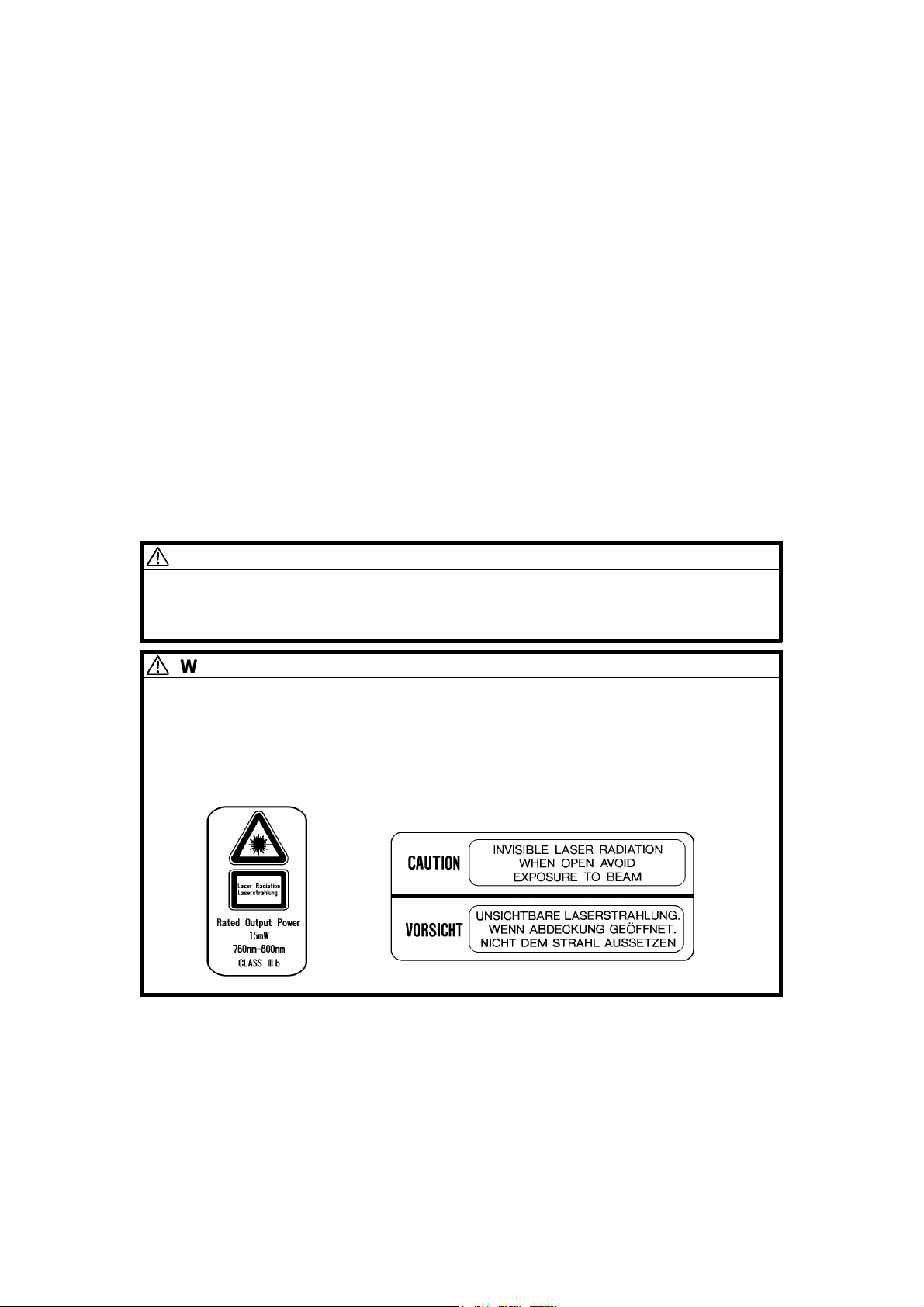
LASER SAFETY
The Center for Devices and Radiological Health (CDRH) prohibits the repair
of laser-based optical units in the field. The optical housing unit can only be
repaired in a factory or at a location with the requisite equipment. The laser
subsystem is replaceable in the field by a qualified Customer Engineer. The
laser chassis is not repairable in the field. Customer engineers are therefore
directed to return all chassis and laser subsystems to the factory or service
depot when replacement of the optical subsystem is required.
DANGER
Use of controls, or adjustment, or performance of procedures other
than those specified in this manual may result in hazardous radiation
exposure.
WARNING FOR LASER UNIT
DANGER: Turn off the main switch before attempting any of the
procedures in the Laser Unit section. Laser be ams
can seriously damage your eyes.
CAUTION MARKING:
A166 b SM
Page 30
TAB INDEX
OVERALL MACHINE INFORMATION
10-BIN SORTER STAPLER A555
DETAILED SECTION DESCRIPTIONS
FILM PROJECTOR UNIT A718
INSTALLATION PROCEDURE
APPENDIX - TIMING CHARTS / SP TABLES
SERVICE TABLES
REPLACEMENT AND ADJUSTMENT
TAB
POSITION 1
TAB
POSITION 2
TAB
POSITION 3
TAB
POSITION 4
TROUBLESHOOTI NG
AUTO REVERSE DOCUMENT FEEDER A548
PAPER TRAY UNIT A550/A549
TAB
POSITION 5
TAB
POSITION 6
TAB
POSITION 7
TAB
POSITION 8
Page 31

Page 32

OVERALL
MACHINE INFORMATION
Page 33

Page 34

Rev. 11/96
1.
SPECIFICATIONS
SPECIFICATIONS
1.1 MACHINE CONFIGURATION
Aficio color (Basic Machine) Edit Machine
2003 (A166) 2103 (A187) 2203 (A189)
Operation Panel
Paper Tray Unit
Sorter/Stapler
ST10
(A555)
250 Sheets Duplex
Copier
Aficio Color
(A166/A187)
20-digit 2-line LCD
ARDF
(DF61)
(A548)
Aficio Color
)
(A189
144 mm x 192 mm
Touch Panel Display
FPU
SPU 3
(A718)
Overall
Machine
Information
BASIC
250-sheet Paper
Tray / Duplex Tray
Paper Tray Unit
PS290
(A549)
500 sheets
x 3 Trays
EDIT
Duplex Tray
PS280
(A550)
500 sheets
x 2 Trays
Type B
(A579)
FP Table
SM 1-1 A166/A187/A189
Page 35

SPECIFICATIONS
1.2 GENERAL SPECIFICATIONS
Configuration: Desk Top
Copy Process: Dry Electrostatic Transfer System
Resolutions: 400 dpi
Gradations: 256 gradations
Originals: Sheet/Book/Object
Original Size: Maximum 11" x 17" /A3
Copy Paper Size:
Maximum Minimum
1/2
Paper Tray Feed
Bypass Feed
11" x 17" /A3 5
1/2
11" x 17" /A3 5
x 8
1/2
x 8
/A5(S)
1/2
/A5(L/S), A6(L)
Copy Paper Weight:
Paper Tray Feed
Bypass Feed
Auto Duplex
Tray
17 to 24 lbs 64 to 90 g/m
14 to 43 lbs 52 to 157 g/m
17 to 28 lbs 64 to 104 g/m
2
2
2
Reproduction Ratios:
1/2
8
" x 11"/11" x 17" version A4/A3 version
Enlargement
Full size
Reduction
Programmable
121, 129, 155, 200, 400% 115, 122, 141, 200, 400%
100% 100%
25, 50, 65, 74, 77, 85, 93% 25, 50, 65, 71, 75, 82, 93%
2 user ratios 2 user ratios
Zoom: From 25% to 400 % in 1% steps.
A166/A187/A189 1-2 SM
Page 36

SPECIFICATIONS
Copying Speed:
1/2
8
" x 11" (S) /A4 11" x 17"/A3
Normal Mode
Full Color (4 scans) 3 cpm 1.5 cpm
Single Color (C, M Y, K) 21 cpm 11 cpm
Single Color (R, B) 4 c pm 3 cpm
Single Color (G) 3 cpm 2.5 cpm
OHP/Thick Paper Mode
Full Color (4 scans) 1.5 cpm 1 cpm
Single Color (C, M Y, K) 2.5 cpm 1.5 cpm
Single Color (R, G, B) 2 cpm 1 cpm
First Copy Time:
1/2
8
" x 11" (S) /A4 11" x 17" /A3
Normal Mode
Full Color (4 scans) 32 seconds 52 seconds
Single Color (K) 15 seconds 20 seconds
Single Color (C, M, Y) 20 seconds 20 seconds
Single Color (R, B) 25 seconds 35 seconds
Single Color (G) 30 seconds 40 seconds
OHP/Thick Paper Mode
Full Color (4 scans) 50 seconds 70 seconds
Single Color (K) 35 seconds 45 seconds
Single Color (C, M, Y) 35 seconds 45 seconds
Single Color (R, B) 40 seconds 55 seconds
Single color (G) 45 seconds 60 seconds
Overall
Machine
Information
Warm-up Time: Approx. 6 minutes (at 68°F / 20°C)
SM 1-3 A166/A187/A189
Page 37

SPECIFICATIONS
Duplexing:
Basic Manual Duplex
Model (A166):
Basic Auto Duplex
Model (A187):
Edit Auto Duplex Model
(A189):
Non-Reprodu ction Ar ea:
Leading Edge:
Side:
Manual Duplexin g in full color and Sin gle
Color mode
Manual & Auto Duplexing in Full Color and
Single Color mode
Manual & Auto Duplexing in Full Color and
Single Color mode
Duplex can be done on 64-104 g/m2 (17-28lb
bond) paper.
Manual Duplexing can be done through the
By-pass table only, and the user should press
the Duplex Side 2 key before copying the
reverse side.
0.2" ± 0.08" (5 mm ± 2 mm)
0.08" ± 0.08" (2 mm ± 2 mm)/
Total less than 0.16" (4 mm)
Trailing Edge
Front side 2.5 mm ± 2.0 mm
Back side 6.0 ± 2.0 mm
(back side trailing edge is adjustable by SP
mode from 0.5 to 10 mm)
Copy Number Input: Number keys, 1 to 99
Copy Number Input
(Auto Duplex):
Number keys
Single Color - 1 to 50: smaller than A3, 11" x 17"
1 to 30: A3, 11" x17"
Full Color 1 to 20: all sizes
Image Density: Auto/Manual (7 steps)
Automatic Reset: Yes (10 to 900 seconds or Off)
Paper Capacity: Tray:
250 sheets x 1 tray
(Basic Manual Dupl ex Mod el: A16 6)
By-pass:
40 sheets Normal paper (80 g/m2)
20 sheets OHP
1 sheet Adhesive paper
A166/A187/A189 1-4 SM
Page 38

Toner Replenishment: Black:
Toner Addition (300 g/cartridge)
Color (Y, M, C):
Toner Addition (100 g/cartridge)
Toner Type E for C, M, Y; Ex for BK
Cyan - EDP# 889766
Magenta - EDP# 889765
Yellow - EDP# 889764
Black - EDP# 889763
Developer Type: F all colors
Cyan - EDP# 889762
Magenta - EDP# 889761
Yellow - EDP# 889760
Black - EDP# 889759
SPECIFICATIONS
Overall
Machine
Information
Copy Tray Capacity: 100 sheets (11" x 17"/A3 and smaller)
Power Source: 120V/60Hz, 220-240V/50,60 Hz
Maximum Power
1.5 kVA
Consumption:
Dimensions (with Platen Cover):
Width Depth Height
Basic Manual Duplex
(A166)
Basic Auto Duplex
(A187)
Edit Auto Duplex
(A189)
620 mm
24.4"
620 mm
24.4"
620 mm
24.4"
700 mm
27.5"
700 mm
27.5"
750 mm
29.5"
632 mm
24.9"
632 mm
24.9"
632 mm
24.9"
Weight: Manual Duplex: 105 kg (231.3 lb)
Auto Duplex: 109 kg (240.1 lb)
Optional Equipm ent: Automatic D ocum ent Fee der : ARDF (A548 )
Sorter Stapler: ST10 (A555)
Film Projector: SPU 3 (A718)
Holder for Film Projector Unit: Type B (A579)
Paper Tray Unit (3 Trays & 2 Trays):
PS290/PS280 (A549/A550)
Key Counter (Procure locally)
SM 1-5 A166/A187/A189
Page 39

SPECIFICATIONS
1.3 DETECTABLE ORIGINAL SIZE BY PLATEN/ARDF
Size
(width x length )
[mm]
A3 (297 x 420)L No Yes No Yes
B4 (257 x 364)L No Yes No Yes
A4 (210 x 297)L No Yes Yes Yes
A4 (297 x 210)S No Yes Yes Y es
B5 (182 x 257)L No Yes No Yes
B5 (257 x 182)S No Yes No Yes
A5 (148 x 210)L No No* No Yes
A5 (210 x 148)S No Yes No Yes
B6 (128 x 182)L No No No Yes
B6 (182 x 128)S No No No Yes
11" x 17" (DLT) Yes No Yes Yes
11" x 15" No No Yes No
10" x 14" Yes No Yes No
8.5" x 14" (LG) Yes No Yes No
8.5" x 13" (F4) No Yes No Yes
8.25" x 13" No No No No
8" x 13"(F) No No Yes No
8.5" x 11" (LT) Yes No Yes Yes
11" x 8.5" (LT) Yes No Yes Yes
8" x 10.5" No No No No
8" x 10" No No Yes No
5.5" x 8.5" (HLT) No* No Yes No
8.5" x 5.5" (HLT) Yes No Yes No
A6 (105 x 148)L No No No No
Inch version Metric version Inch version Metric version
Platen ARDF
* : For A5 lengthwise/HLT, SP4-303 can be used to select "Cannot detect
original size" or "A5 lengthwise/5.5" x 8.5"(HLT)".
A166/A187/A189 1-6 SM
Page 40

1.4 COPY PAPER SIZE
SPECIFICATIONS
Size
(width x length)
[mm]
A3 (297 x 420)L No Yes Yes Yes Yes Yes
B4 (257 x 364)L No Yes Yes Yes Yes Yes
A4 (210 x 297)L Yes Yes Yes Yes Yes Yes
A4 (297 x 210)S Yes Yes Yes Yes Yes Yes
B5 (182 x 257)L No Yes No Yes Yes Yes
B5 (257 x 182)S No Yes No Yes Yes Yes
A5 (148 x 210)L No No No No Yes Yes (1)
A5 (210 x 148)S No Yes Yes Yes Yes Yes (2)
B6 (128 x 182)L No No No No Yes Yes (1)
B6 (182 x 128)S No No No No No No
11" x 17" (DLT) Yes Yes Yes Yes Yes Yes
11" x 15" Yes No Yes No Yes Yes
10" x 14" Yes No Yes No Yes Yes
8.5" x 14" (LG) Y es No Yes No Yes Yes
8.5" x 13" (F4) Yes Yes Yes Yes Yes Yes
8.25" x 13" No No Yes Yes Yes Yes
8" x 13"(F) No No Yes Yes Yes Yes
8.5" x 11" (LT) Yes Yes Yes Yes Yes Yes
11" x 8.5" (LT) Yes Yes Yes Yes Yes Yes
8" x 10.5" No No Y es No Yes Yes
8" x 10" Yes No Yes Yes Yes Yes
5.5" x 8.5" (HLT) No No No No Yes Yes (1)
8.5" x 5.5" (HLT) Yes No Yes Yes Yes Yes (2)
A6 (105 x 148)L No No No No Yes Yes (2)
Inch
version
Trays in the main body Bypass
Paper Tray Duplex Tray
Metric
version
Inch
version
Metric
version
All
versions
Optional
S.Stapler
Overall
Machine
Information
Yes (1): Stapling is not allowed.
Yes (2): Using the Proof Tray only. Sorter bins cannot be used.
SM 1-7 A166/A187/A189
Page 41

SPECIFICATIONS
1.5 PAPER SIZES AVAILABLE WITH APS
– For metric machines –
200
173
163
141
122
115
100
93
87
82
75
~
~
~
~
~
~
~
~
~
~
~
174
164
142
123
116
101
94
88
83
76
72
A3
B4
A4L
B5L
A5L
A4S
B5S
A5S
8.5
x 11
x 8.5
8.5
x 13
x 15
––––––A3–B4––A4L8.5
–––––A3B4––A4L8.5
x 13
– – – A3 B4 – A4L 8.5
––A3B4–A4LB5L––A5L––––––
A3 B4 – A4 L B5L – A5L – – – – – – – – –
––––––A4S–B5S––A5S––––
–––––A4SB5S––A5S––––––
–––A4SB5S–A5S–––––––––
––––––8.5
x11
11
––––––11x
8.5
––––A3–8.5
x 13
11
––––––11x15–––––––––
B5L– –A5L– – – –
x 13
–––––––––
–––––––––
––A4LB5L––––A5L
71
65
61
57
50
~
~
~
~
~
66
62
58
51
B5L – A5L
x 13
B5L– –A5L–
: Not allowed in platen cover mode. L: Lengthwise S: Sideways
– For inch machines –
200
176
~
~
177
156
11x17
11x15
8.5x14
8.5x11
5.5x8.5
8.5x5.5
11x8.5
8x10
10x14
8x13
– – – – – 11x17 11x17 11x15 8.5
– – – – – 11x15 11x15 – 8.5
––––11
– – 11 x17 – 8.5
11
x1711x15
–––11
–––––11
– – – 11x17 10x14 8x10 – – – – 5.5
–––––10x14–8.5
–––11x17–8x13––––5.5
155
~
130
8.5
x14
129
~
122
8.5
x11
x8.5
121
100
~
~
101
94
8.5
x17
x14
x11
–5.5
x8.5
–8.5
x5.5
x8.5
93
85
77
74
65
~
~
~
~
~
86
78
75
66
51
–8.5
x14
8.5x11 – 5.5
x14
––8.5
x11
––––5.5
––––––
––––––
––––8.5
8.5
x14
x11
x11
––5.5
x8.5
x5.5
x8.5
––5.5
x8.5
50
~
5.5
x8.5
x8.5
x8.5
–
–
–
x14
–
: Not allowed in platen cover mode.
A166/A187/A189 1-8 SM
Page 42

SPECIFICATI ONS
NOTE:
1) The tables show which copy paper size is selected for each
original size for zoom ratios from 50 to 200 %.
2) When a zoom ratio is specified, APS automatically selects a
paper size that can guarantee the quality of the magnified copy
image if there is a paper size available for the equivalent
standard rep rod uction rati o.
3) If paper of the detected size has run out, the machine displays the
message "Set xx $ paper in tray" and stops the job (copying is
enabled).
4) For "–" in the above tables, the machine displays the message
"Cannot detect original size" and stops the job (copying is
enabled). The selected paper feed tray does not change.
5) When 49% or less or 201% or more is selected, APS works in the
same way as described in Note 4 above.
6) APS also supports the by-pass feed table (except for
non-standard paper sizes). When a selected paper size can only
be fed from the by-pass feed table, the machine displays a
warning to instruct the user to use the by-pass feed table.
7) APS does not support A6 and B6 sizes.
Overall
Machine
Information
1.6 NOISE EMISSION
Sound pressure level (The measurements are made in accordance with ISO
7779 at the operator positions.)
Copier only Full system*
Less than 61 dB (A) Less than 65 dB (A)
* Full system: Copier with document feeder, 500 sheets x 3 trays unit, F PU,
and a sorter stapler.
Sound power level (The measurements are made in accordance with ISO
7779.)
Copier only Full system*
Stand-by Less than 54 dB (A) Less than 58 dB (A)
Copying
(This value is for the
black copy mode.)
* Full system: Copier with document feeder, 500 sheets x 3 trays unit, F PU,
and a sorter stapler.
Less than 67 dB (A) Less than 71 dB (A)
SM 1-9 A166/A187/A189
Page 43

SPECIFICATIONS
1.7 POWER CONSUMPTION
(1) Maximum power consumption
1.5 kVA
(2) Average power consumption
A189 Copier +
DJF + Sorter
Value for standby
minus 7 W
NOTE:
A189 Copier
Standby
Warm-up
Copying
Energy Saver
Mode
0.25 kW 0.5 kW
1.25 kW 1.25 kW
1.15 kW 1.15 kW
Value for standby
minus 7 W
1) Copying was done in the 1C (A3) repeat mode.
2) The power consumption in energy saver mode was measured
with the fusing lamp off.
1.8 DISPLAY EDITOR SPECIFICATION
Scanned image
Displayed image
Area specification
procedure
The copier’s scanner scans the image.
•
Maximum A3/DLT (11" x 17"): Reduced image display
•
144 x 192 mm, 16-gradation (4 bit/pixel) monochrome
•
640 x 480 dots, 0.33 mm/pixel
•
Reduces the dpi of scanned images to approximately 33 dpi and
•
displays the entire image.
Zoom display: 3 levels (50 dpi, 67 dpi, 100 dpi)
•
Display processing time: 2 seconds or less
•
Move the arrow in the screen by using the cursor key and enter a
•
point by pressing the coordinate entry key.
A166/A187/A189 1-10 SM
Page 44

2.
MACHINE CONFIGURATION
MACHINE CONFIGURATION
2.1 COPY PROCESSES AROUND THE DRUM AND BELT
2
1
11
3
4
5
6
9
13
10
7
Overall
Machine
Information
8
12
1. Drum Charge
In the dark, the charge corona unit gives a negative charge to the
organic photoconductive (OPC) drum. The grid plate ensures that corona
charge is applied uniformly. The charge remains on the surface of the
drum because the OPC layer has a high electrical resistance in the dark.
The amount of negative charge on the drum is proportional to the
negative voltage applied to the drum charge corona wire and casing.
2. Laser Exposure
A laser beam is reflected onto the drum by the polygon and drum
mirrors. This forms an electrical latent image on the drum surface. The
amount of charge remaining as a latent image on the drum depends on
the laser beam intensity.
3. Drum Potential Detection
The drum potential sensor detects the strength of the electric field on the
charged drum. The sensor output is one of the signals used in process
control.
SM 1-11 A166/A187/A189
Page 45

MACHINE CONFIGURATION
4. Development
The negatively charged toner is attracted to the latent image on the drum
surface. Toner particles are electrostatically attracted to the area of the
drum surface where the laser reduced the negative charge on the drum.
The development unit is a revolver-type, containing separate
development sections for each color toner.
5. Image Density Detection
When the laser forms a sensor pattern on the drum surface, the ID
sensor measures the image density of these patterns. The output signal
is used in process control to regulate toner supply.
6. Pre-transfer Lamp
After development, the pre-transfer lamp reduces the potential of the
image background, right before the first belt transfer (in 2C/3C/4C mode).
This ensures that electrostatic attraction between belt and drum is about
the same for each color toner transfer, which ensures that the color toner
images are synchronized properly.
7. Belt Transfer
Toner on the drum is attracted to the transfer belt by the belt corona unit.
8. Belt Lubrication
The transfer belt lubricant brush applies a small amount of lubricant to
the surface of the transfer belt. This aids the belt cleaning blade in
removing waste toner from the transfer belt.
9. Belt Cleaning
The cleaning blade removes any toner on the belt after paper transfer.
10. Drum Cleaning
The drum cleaning brush roller removes remaining toner from the drum.
The cleaning brush also applies lubricant. This aids in drum cleaning.
11. Quenching
The light from the quenching lamp electrically neutralizes the charge on
the drum surface. This prepares the drum for the next copy cycle.
12. Paper Transfer
When all toner has been transferred from the drum to the transfer belt,
the charged toner on the transfer belt is attracted to the paper by the
paper transfer unit. This charge is applied to the underside of the paper.
13. Paper Separation
The copy paper separates from the transfer belt due to the belt’s
curvature. This curvature allows the paper to naturally fall away from the
transfer belt. The discharge brush aids in the separation process by
discharging any remaining electric charge from the paper.
A166/A187/A189 1-12 SM
Page 46

3.
MAJOR UNIT OVERVIEW
MAJOR UNIT OVER VI EW
1
2
3
4
10
9
8
Overall
Machine
Information
5, 6
7
SM 1-13 A166/A187/A189
Page 47

MAJOR UNIT OVERVIEW
1. Copier
1. Dimensions (W x D x H):
Basic machine - 620 x 700 x 632 mm [24.4"x27.6"x25.2"] (with paper
tray unit: 620 x 700 x 1010) [24.4"x27.6"x40.1"]
Edit machine - 620 x 750 x 632 mm [24.4"x29.8"x25.2"] (with paper tray
unit: 620 x 750 x 1010) [24.4"x29.8"x40.1"]
2. The printer unit, system control unit, and scanner unit are independent
modules connected wi th an interf ace.
2. Scanner Unit
1. 400 dpi (8 bits/dot) scanning in both main and sub scan directions
2. 3-line CCD with reduction optics
3. Exposure lamp: Halogen lamp
4. 5-phase stepper mot or drive
3. Drum Unit
1. The drum unit contains the photoco nduct or dru m, char ge coron a unit,
and cleaning unit
2. Charge corona unit: Single scorotron charge
3. Quenching Lamp: Red LEDs
4. Drive: Synchronized with the transfer belt (dc brushless motor and
flywheel); full speed = 105 mm/s
5. Potential sensor and ID sensor incl ude d
4. Fusing and Paper Ex it Se cti on
1. Fusing: Silicone roller fusing (both hot and pressure rollers)
2. Oil application method: Double roller
3. Cleaning: Roller cleaning for the hot roller
Cleaning blade for the pressure roller
4. OHP/Thick paper mode: Half speed (52.5 mm/s)
5. Development and Toner Supply
1. Development: Two-component magnetic brush development
2. Development switching: Revolver System
3. Image density control: ID sensor and Po tent ial sens or (Pro cess contro l )
4. Toner supply
Black: Screw-in bottle (300 g)
Color: Sector cartridge (100 g)
5. Toner supply unit: Front of development unit (rotation type)
A166/A187/A189 1-14 SM
Page 48

MAJOR UNIT OVER VI EW
6. Toner and Developer
1. Color toner: Type E
2. Black toner : Type EX
3. Developer: Type F
7. Paper Feed and Transport
1. Paper Tray Unit (A166 copier only)
Corner Separation System
•
Front loading tray (250 sheets) and By-pass table
•
2. Transport: Transp ort belt with fan
3. Duplex unit (A187, A189 copier only)
Duplex unit and By-pass table
•
4. Paper Tray Unit (option): • 500 sheets x 3 trays (FRR Feed System)
• 500 sheets x 2 trays (FRR Feed System)
8. Transfer and Belt Drive
1. Transfer belt: Full time contact with the drum
2. Belt transfer: Single corona charge
3. Paper transfer: Single corona charge
4. Registration: Synchronization by the transfer belt H.P. sensor
5. Drive: Synchronized with the drum (same motor)
6. Separation: Curvature separation + discharge brush
7. Transfer cycle: 1 belt rotation/A4
8. Belt cleaning: Counter blade
9. Lubrication: Brush roller with lubricant bar
Overall
Machine
Information
9. Printer Unit
1. Optics: 6-sided polygon mirror + 2 fθ lenses and BTL
2. Polygon motor (16 535 rpm ), with bal l bear i ng
3. Resolution: 400 dpi
4. Modulation: PM and PWM
10. System Control Unit (SCU)
1. Basic machine: The SCU is on the back side of the operation panel
(20-digit 2-line LCD)
2. Edit machine: The SCU is under the scanner unit and connected to the
touch panel display (640 x 480 dots).
Note for Ricoh Corporation:
A166 = model Aficio Color 2003
A187 = model Aficio Color 2103
A189 = model Aficio Color 2203
SM 1-15 A166/A187/A189
Page 49

PARTS LAYOUT
4.
PARTS LAYOUT
4.1 MECHANICAL COMPONENT LAYOUT
5 6
4
3
2
1
7
1098
11
1312
14
15
16
17
19
20
21
22
18
26
1. Paper Tray (A166)
Duplex Tray
(A187/189)
2. Pressure Roller
3. Hot Roller
4. 2nd Scanner
5. 1st Scanner
6. Development Unit
7. Drum Mirror
8. Toner Shield Glass
9. Barrel Toroidal
Lens (BTL)
25
10. Charge Corona Unit
11. Lens
12. 2nd fθ Lens
13. CCD Board
14. 1st fθ Lens
15. Polygon Mirror
16. Drum Cleaning Unit
17. Lubricant Brush
18. By-pass Feed Table
19. Transfer Belt
24
23
20. OPC Drum
21. Registration Rollers
22. Relay Roller
23. Belt Transfer
Charge Unit
24. Paper Transfer
Charge Unit
25. Belt Cleaning Unit
26. Transport Belt
A166/A187/A189 1-16 SM
Page 50

4.2 PCB (A166/A187 COPIERS)
6
5
7
PARTS LAYOUT
Overall
Machine
Information
8
4
3
2
1
18
1. RAM Board
2. SCU Board
3. AC Drive/DC Power
Supply Board
9
10
11
12
13
14
16
17
11. I/O Control Board 2
12. By-pass Paper Width
Detection Board
13. I/O Control Board 1
15
4. Operation Panel
14. High Voltage Supply
Board
5. Scann er Mot or Dri ve
Board
15. Laser Synchronizing
Detector Board 2
6. Scanner IPU Board
16. Laser Synchronizing
7. CCD Board
8. Lamp Regulator
9. IDU Board
10. Main Control Board
SM 1-17 A166/A187/A189
Detector Board 1
17. LD Drive Board
18. Duplex Control Board
(Except A166)
Page 51

PARTS LAYOUT
4.3 PCB (A189 COPIER)
20
19
23
22
21
19. SCU Board
20. Operation Panel
21. Extended IPU Board
22. Duplex Control Board
23. RAM Board
A166/A187/A189 1-18 SM
Page 52

4.4 SOLENOIDS AND CLUTCHES
3
PARTS LAYOUT
Overall
4
Machine
Information
5
6
2
1
1. Transfer Belt Cleaning SOL
2. Toner Supply Release SOL
3. Junction Gate SOL
(A187/A189 only)
7
8
9
10
6. Registration CL
7. Main By-pass Feed Pick-up
SOL
8. By-pass Feed CL
4. Sub By-pass Feed Pick-up
9. Paper Feed CL
(A166 only)
SOL
10. Vertical Transport CL
5. Transfer Belt Lubricant SOL
SM 1-19 A166/A187/A189
Page 53

PARTS LAYOUT
4.5 SWITCHES AND HEATERS
11
10
9
12
13
14
8
15
7
16
6
5
4
17
18
3
19
2
20
1
21
22
1. Lower Tray Heater
2. Pressure Roller Thermofuse
3 . Pressure Roller Lamp
4. Fusing Lamp
5. Pressure Roller Thermistor
6. Main Switch
7. Front Door Switch
8. Fusing Thermofuse
9 . Paper Exit Door Switch
(A187/A189 only)
10. Exposure Lamp
11. Thermostat
12. Optics Anticondensation
Heater
13. Fusing Thermistor
14. Charge Corona Unit
15. Quenching Lamp
16. Tray Paper Size SW
(A166 only)
17. Paper T r ansfer Charge Unit
18. Belt Transfer Charge Unit
19. Drum Heater
20. By-pass Feed Table SW
21. Vertical Tr anspo rt SW
22. Pre-transfer Lamp
A166/A187/A189 1-20 SM
Page 54

PARTS LAYOUT
4.6 SENSORS
24
23
7
8
6
5
4
9
10
11
12
13
Overall
Machine
Information
14
15
3
16
2
17
1
18
22
21
20
19
1. Used Toner Sensor
2. Color Toner Cartridge
Sensor
3. Oil End Sensor
4 . Revolver H.P. Sensor
5. Bk Toner Cartridge Sensor
6. Scanner H.P. Sensor
7. Original Width Sensor
8. Paper Exit Sensor
9 . Drum Potential Sensor
10. Platen Cover Position
Sensor
11. Scanner Unit Lift Sensor
12. Original Length Sensor 1
13. Original Length Sensor 2
15. Registration Sensor
16. Tray Paper End Sensor
(A166 only)
17. By-pass Feed Paper End
Sensor
18. Vertical Tr anspo rt Se nsor
19. Transfer Belt H.P. Sensor
20. Duplex Paper End Sensor
(A187/A189 only)
21. Duplex Turn Sensor
(A187/A189 only)
22. Duplex Entrance Sensor
(A187/A189 only)
23. Side Fence Jogger HP
Sensor
(A187/A189 only)
24. End Fence Jogger HP
Sensor
(A187/A189 only)
14. ID Sensor
SM 1-21 A166/A187/A189
Page 55

PARTS LAYOUT
4.7 MOTORS
10
2
3
4
5
6
1
7
9
1. Toner Supply Motor
2. Scanner Motor
3. Revolver Drive Motor
4. Development Drive Motor
5. Polygon Motor
6. Drum Motor
8
7. Main Motor
8. Duplex Feed Motor
(A187/A189 only)
9. Side Fence Jogger Motor
(A187/A189 only)
10. End Fence Jogger Motor
(A187/A189 only)
A166/A187/A189 1-22 SM
Page 56

4.8 DRIVE LAYOUT
7
6
PARTS LAYOUT
8
Overall
Machine
Information
5
4
3
2
1
1. Paper Feed Clutch
9
10
11
7. Transfer Belt Drive Gear
2. Vertical Transport Clutch
3. Registration Clutch
4. By-pass Feed Clutch
5. Drum Drive Gear
8. Development Drive Gear
9. Revolver Drive Gear
10. Transport Unit Drive Gear
11. Fusing Unit Drive Gear
6. Transfer Belt Lubricant
Gear
SM 1-23 A166/A187/A189
Page 57

PARTS LAYOUT
4.9 FANS AND AIR FLOW
8
9
10
7
11
6
12
5
4
13
3
2
14
1
15
1. Development Inlet Fan
2. Transport Fan 1
3. Transport Fan 2
4. Front Power Supply
9. Exhaust Fan
10. Fusing Fan
11. Charge Inlet Fan
12. Optics Exhaust Fan
Board Fan
13. Scanner Board Cooling
5. Paper Exit Fan
6. Optics Cooling Fan 1
7. Optics Cooling Fan 2
Fan
14. Rear Transfer Fan
15. Front Transfer Fan
8. Rear Power Supply Board
Fan
A166/A187/A189 1-24 SM
Page 58

4.10 COUNTERS (A166/A187 COPIERS)
1
PARTS LAYOUT
2
Overall
Machine
Information
1. Main Counter
2. Back-up Counter (stored in the RAM board on the SCU board)
SM 1-25 A166/A187/A189
Page 59

PARTS LAYOUT
4.11 COUNTER (A189 COPIER)
1
2
1. Main Counter
2. Back-up Counter (stored in the RAM board on the SCU board)
A166/A187/A189 1-26 SM
Page 60

5.
ELECTRICAL COMPONENT LIST
ELECTRICAL CO MPO N ENT L IST
5.1 PRINTED CIRCUIT BOARDS
Symbol Name Function Remarks
PCB1 Lamp regulator Supplies dc power for the exposure lamp.
PCB2
PCB3
PCB4
PCB5
PCB6 Main control board Controls the printer sequence.
PCB7
PCB8
PCB9 LD drive board Controls the LD output.
PCB10
PCB11
PCB12 IDU board Discriminates image for anti-counterfeiting
PCB13
PCB14
PCB15
PCB16 RA M board Stores the copy process data and counters.
PCB17 Operation panel Used to operate the copier.
PCB18
PCB19
Scanner motor drive
board
CCD board Converts the light reflected from the original
AC drive/
DC power suppy
Scanner IPU board Converts the RGB image signal from the
I/O control board 1 I nterfaces the sensors, clutches, solenoids
I/O control board 2 I nterfaces the sensors, clutches, solenoids
Laser synchronizing
detector board 1
Laser synchronizing
detector board 2
By-pass paper width
detection board
High voltage supply
board
System control unit
(SCU) board
Extended IPU board Converts scanned image data and sends it
Duplex control board Cont r ols the duplex unit. A187/A189
Supplies dc power for the scanner motor.
into signals.
Supplies ac and dc power.
CCD to a KCMY signal and sends it to the
printer and SCU.
and motors in the printer module with the
main control board. Includes temperature
and humidity sensors.
and motors in the printer module with the
main control board.
Detects laser main scan synchronization
while writing the latent image to the drum.
Detects laser main scan synchronization
while writing the latent image to the drum.
Detects the paper width in the by-pass feed
table.
Supplies power to the corona units.
Controls the system.
to SCU for the display. Performs image
processing on an area specified in the
display.
A189
copier
only
copiers
only
Overall
Machine
Information
SM 1-27 A166/A187/A189
Page 61

ELECTRICAL COMPONENT LIST
5.2 SOLENOIDS
Symbol Name Function Remarks
SOL1
SOL2
SOL3
SOL4
SOL5
SOL6
Sub by-pass feed
pick-up solenoid
Main by-pass feed
pick-up solenoid
Toner supply
release solenoid
Transfer belt
cleaning solenoid
Transfer belt
lubricant solenoid
Junction gate
solenoid
Lowers the pick-up roller.
Lowers the pick-up roller.
Releases the toner supply motor.
Controls the contact and release
operation of the belt cleaning blade.
Controls the contact and release
operation of the lubrication brush on
the transfer belt.
Raises the junction gate for the duplex
copier.
A187/A189 copier
only
5.3 CLUTCHES
Symbol Name Function Remarks
CL1
CL2
CL3
CL4
By-pass feed clutch Transmits the drive to the by-pass feed
section.
Registration clutch Transmits the drive to the registration
rollers.
Vertical transport
clutch
Paper feed clutch Transmits the drive to the paper feed
Transmits the drive to the vertical
transport section.
section.
A166 copier only
A166/A187/A189 1-28 SM
Page 62

ELECTRICAL CO MPO N ENT L IST
5.4 SWITCHES
Symbol Name Function Remarks
SW1 Main switch Turns the power to the copier on or off.
Front door switch Opens the dc line to the high voltage
SW2
SW3
SW4
SW5
SW6
SW7
SW8
SW9
Front door switch Opens the dc line to the main control
Front door switch Opens the dc line to the main control
Front door switch Opens the dc line to I/O control board 2
Vertical transport
switch
By-pass feed table
switch
Tray paper size
switch
Paper exit door
switch
supply board when the front door is
open.
board and LD unit when the front door
is open.
board and LD unit when the front door
is open.
when the front door is open.
Detects if the vertical transport door is
open or closed.
Detects if the by-pass feed table is
open or closed.
Detects the size of paper on the paper
tray.
Detects if the paper exit door is open or
closed.
A166 copier only
A187/A189
copiers only
Overall
Machine
Information
5.5 LAMPS
Symbol Name Function Remarks
L1 Fusing lamp Provides heat to the hot roller.
L2
L3
L4
L5
Pressure roller
lamp
Exposure lamp Applies high intensity light to the
Quenching lamp
(QL)
Pre-transfer l amp
(PTL)
Provides heat to the pressure roller.
original for exposure.
Neutralizes any charge remaining on
the photoconductor.
Reduces the charge remaining on the
drum before the transfer process is
started (except for the image area).
SM 1-29 A166/A187/A189
Page 63

ELECTRICAL COMPONENT LIST
5.6 HEATERS
Symbol Name Function Remarks
Optics
H1
H2
H3 Lower tray heater Keeps paper dry on the paper feed tray.
anticondensation
heater
Drum heater Prevents moisture from forming around
Prevents moisture from forming on the
optics.
the drum.
5.7 THERMISTORS
Symbol Name Function Remarks
TH1
TH2
Fusing thermistor Monitors the temperature of the hot
roller.
Pressure roller
thermistor
Monitors the temperature of the
pressure roller.
5.8 T HERMOFUSES
Symbol Name Function Remarks
TF1 Fusing thermofuse P r otects the hot roller from overheating.
TF2
Pressure roller
thermofuse
Protects the pressure roller from
overheating.
5.9 T HERMOSTAT
Symbol Name Function Remarks
TS1
Thermostat Prevents the halogen lamp from
overheating.
A166/A187/A189 1-30 SM
Page 64

ELECTRICAL CO MPO N ENT L IST
5.10 SENSORS
Symbol Name Function Remarks
S1
S2
S3 Scanner HP sensor Detects the scanner home position.
S4
S5 Paper exit sensor Detects a paper jam at the paper exit.
S6
S7
S8
S9
S10
S11
S12
S13 Used toner sensor Detects if the used toner tank is full.
S14
S15
S16
S17
S18
S19
S20
S21
S22
S23
S24
Platen cover
position sensor
Scanner unit lift
sensor
Transfer belt HP
sensor
Color toner
cartridge sensor
Drum potential
sensor
ID sensor Detects the density of the sensor
Revolver HP
sensor
Bk toner cartridge
sensor
Registration sensor Detects a paper jam at the registration
Vertical transport
sensor
By-pass feed
paper end sensor
Tray paper end
sensor
Side fence jogger
HP sensor
End fence jogger
HP sensor
Duplex paper end
sensor
Duplex entrance
sensor
Duplex turn sensor Detects when copy paper is being
Original width
sensor
Original length
sensor 1
Original length
sensor 2
Oil end sensor Detects if there is silicone oil in the oil
Detects if the platen cover is up or
down.
Detects if the scanner unit is lifted or
not.
Detects the transfer belt mark.
Detects the presence of color toner
cartridges.
Detects the potential on the drum
surface for process control.
pattern image on the drum for process
control.
Detects if the revolver is at the home
position.
Detects if the black toner cartridge is
installed.
section.
Detects a paper jam at the vertical
transport section.
Detects if there is paper on the by-pass
feed table.
Detects if there is paper on the paper
feed tray.
Detects the home position of the duplex
unit side fence.
Detects the home position of the duplex
unit end fence.
Detects if there is paper in the duplex
unit.
Detects when copy paper comes into
the duplex unit.
reversed in the duplex unit.
Detects the original width.
Detects the original length.
Detects the original length.
tank.
A166 copier only
A187/A189
copiers only
A187/A189
copiers only
A187/A189
copiers only
A187/A189
copiers only
A187/A189
copiers only
Overall
Machine
Information
SM 1-31 A166/A187/A189
Page 65

ELECTRICAL COMPONENT LIST
5.11 MOTORS
Symbol Name Function Remarks
M1 Scanner motor Drives the scanner.
M2 Polygon motor Drives the polygon mirror.
M3
M4 Drum motor Drives the drum and transfer belt.
M5 T oner supply motor Supplies toner.
M6
M7 Revolver drive motor Rotates the revolver unit.
M8
M9
M10
Main motor Drives the paper feed/transport section and
fusing units.
Development drive
motor
Side fence jogger
motor
End fence jogger
motor
Duplex feed motor Drives the paper feed roller in the duplex
Rotates the development roller.
Drives the duplex unit side fences. A187/A189
Drives the duplex unit end fences. A187/A189
unit.
copiers
only
copiers
only
A187/A189
copiers
only
5.12 FAN MOTORS
Symbol Name Function Remarks
FM1 Optics exhaust fan Cools the scanner unit.
FM2 Optics cooling fan 1 Cools the scanner unit.
FM3 Optics cooling fan 2 Cools the scanner unit.
FM4
FM5 Development inlet fan Cools the development unit.
FM6 Rear transfer fan Draws air from the transfer belt unit.
FM7
FM8
FM9
FM10 Fusing fan Cools the development unit.
FM11 Exhaust fan Draws air out of the copier.
FM12 Front transfer fan Draws air out of the transfer belt unit.
FM13
FM14 Paper exit fan Cools the development unit.
FM15
Scanner board
cooling fan
Transport fan 1 Draws air into attract the copy paper to the
Transport fan 2 Draws air into attract copy paper to the
Charge inlet fan Provides air flow around the charge corona
Rear power supply
board fan
Front power supply
board fan
Cools the scanner unit.
transport belt.
transport belt.
unit and ID sensor.
Cools the power supply unit.
Cools the power supply unit.
A166/A187/A189 1-32 SM
Page 66

ELECTRICAL CO MPO N ENT L IST
5.13 COUNTER
Symbol Name Function Remarks
CO1
Main counter Counts up the number of scans for Bk
and color copying.
Overall
Machine
Information
SM 1-33 A166/A187/A189
Page 67

Page 68

DETAILED SECTION
DESCRIPTIONS
Page 69

Page 70

1.
PROCESS CONTROL
1.1 OVERVIEW
PROCESS CONTRO L
Potential
Sensor
Development
Roller
[A]
Drum
[B]
Section
Detailed
Descriptions
[A]: Toner Supply Motor
[B]: Charge Corona Unit
SM 2-1 A166/A187/A189
Page 71

PROCESS CONTROL
Rev. 1/97
This machine uses two control methods:
•
Latent Image Control (every process control self check)
•
Toner Supply Control (every copy)
Latent Image C ontrol
Latent image control controls the development potential to maintain the
density of the toner image on the drum. It does this by compensating for
variations in drum chargeability and toner chargeability.
The machine uses the drum potential sensor to measure the drum’s
response to a standard applied voltage. Then it uses the image density (ID)
sensor to measure drum reflectivity and the density of a standard sensor
pattern. These tests are done during the process control self check, which is
done every 150 copies and at other times such as after replacing the
developer.
Depending on the results of the self check, the machine adjusts the grid
voltage, the development bias, and the laser diode current to maintain the
correct drum potential s.
Toner Su pp l y C on tr ol
Toner supply control maintains a constant amount of toner on the ID sensor
pattern. To do this, the machine monitors the response of the ID sensor to a
standard pattern printed for each color after every color development cycle
and uses this to control the toner supply motor with a fuzzy logic algorithm.
A166/A187/A189 2-2 SM
Page 72

PROCESS CONTRO L
1.2 PROCESS CONTROL MEASUREMENT TIMING
The machine uses outputs from the drum potential sensor and the ID sensor.
Some outputs are measured every color development cycle during each
copy, and others are only measured during the process control self check
procedure.
The following table shows the sensor outputs that are used by process
control, and the times that these outputs are measured.
Sensor Output: Measurement Timing
SG
V
SP
V
for toner supply control [VSP(toner)] During each copy, after writing each color
Drum Potential During the process control self check, the
SP
V
for potential control [VSP(pot)] After the above 12-grade gradation pattern
Adjusted to 4.0 ± 0.1 V during the process
control self check.
image to the drum, the laser diode wr ites the
ID sensor pattern for toner supply control on
the drum. (This is a single-grade pattern.)
The ID sensor measures the density of the
developed ID sensor pattern for each color,
SP
SP
(toner).
(pot).
and this is used as V
laser diode writes a 12-grade gradation
pattern for each color on the drum. The
drum potential sensor measures the
potential on each grade.
has been developed, the ID sensor
measures the density of the developed
gradation pattern for each step and stores
these values as V
Section
Detailed
Descriptions
NOTE:
VSG: Output voltage from the ID sensor when it measures the bare
drum.
VSP: Output voltage from the ID sensor when it measures the image
density of a sensor pattern.
Process Control Self Check: See section 4.
SM 2-3 A166/A187/A189
Page 73

PROCESS CONTROL
1.3 POTENTIAL CONTROL (LATENT IMAGE CONTROL)
1.3.1 Concept
Latent image control adjusts the development potential to maintain the
density of the toner image on the drum. It does this by compensating for
variations in drum chargeability and toner chargeability.
Development Potential (VDP)
The development potential (VDP) is the difference between the development
bias voltage and the voltage of areas of the drum that have been discharged
by laser exposure at full power. If changes in this potential are not accounted
for, the color balance will be poor.
– Factors that change the development potential –
Drum Chargeability
After long usage following installation or PM, drum chargeability will
gradually change due to the following factors:
Dirty charge corona and grid plate
Changes in the drum characteristics with age (OPC wear) and
temperature.
Also, as the drum gets older, its sensitivity (response to light) gradually
decreases. This leads to an increase in residual voltage in exposed areas of
the drum after laser exposure, and on all areas after quenching.
Toner Chargeability
Toner chargeability varies with humidity, and this affects the image density
even if the toner concentration is kept constant.
When humidity is low, toner chargeability increases resulting in lower image
density. When humidity is high, toner chargeability decreases resulting in
higher image density.
Also, after long usage following installation or PM, the surface of carrier
particles is gradually coated with melted toner (this is known as filming). This
decreases the tone r chargeability.
How the machine maintains the optimum development potential
The machine uses the drum potential sensor to detect changes in the drum’s
response to a standard applied voltage. It also uses the image density (ID)
sensor to detect changes in drum reflectivity and the density of a standard
sensor pattern. These tests are done during the process control self check,
which is preformed every 150 copies and other times, such as after the main
switch is turned on.
The machine calculates the current VDP from a series of M/A values
obtained from image density and potential readings off the 12 grades of the
VSP sensor pattern on the drum. To make sure that VDP is kept at an
optimum value, the machine refers to a look-up table of current VDP against
VD, VL, and VB (this is known as the pointer table).
A166/A187/A189 2-4 SM
Page 74

PROCESS CONTRO L
There are 20 combinations in this table. The machine chooses the
combination that is closest to the current VDP, and will use these values of
VD, VL, and VB for copying until the next process control self check. The
selected combination is based on actual image conditions, using the density
of sensor pattern s on the drum, as to better maintain proper copy quality.
M/A: MASS/AREA Amount of toner per unit area on the drum (mg/cm2)
VD: Drum potential without exposure - to adjust this, the machine adjusts the
charge corona grid voltage (VG)
VL: Drum potential with the strongest exposure - to adjust this, the machine
adjusts the laser diode input current (ILD)
VB: Development bias
1.3.2 Process Control Self Check
The drum potential process control adjustments take place during the
process control self check. This self check is done at three different times.
1. Forced Process Control Self Check
When installing the machine or replacing the developer, the process
control self check must be performed (SP 3-126). The machine must be
in standby mode for 10 minutes at least before doing this.
Section
Detailed
Descriptions
2. Initial Process Control Self Check
After the main switch has been turned on and if the hot roller
temperature is below 100 degrees, the process control self check is done
automatically. (The setting of SP 3-125 must be kept at 0 for this to be
done automatically.)
3. Interval Process Control Self Check
If more than 150 copies have been made since the last process control
self check, after the copy job is completed.
The process control self check itself takes about 3 minutes. However, in
addition, the development unit rotates as explained in the following note,
so the total time is extended.
NOTE: Forced and Initial Process Control Self Checks:
Just before the end of the initial process control self check, the
development unit rotates 10 revolutions to supply Bk toner to the
hopper section. As a result, the total time for this self check is 4 - 5
minutes.
Interval Process Control Self Check:
The drum potential sensor calibration is omitted (see section 1.3.4).
However, just before the end of internal process control self check,
the development unit rotates 10 revolutions to supply black toner.
Therefore, this self check takes about 2 - 3 minutes.
SM 2-5 A166/A187/A189
Page 75

PROCESS CONTROL
1.3.3 Process Control Self Check Procedure
*
*NOTE:
In the interval process control self check, the Drum Potential Sensor
Calibration step is skipped.
A166/A187/A189 2-6 SM
Page 76

1.3.4 Drum Potential Sensor Calibration
PROCESS CONTRO L
Section
Detailed
Descriptions
[A]
[D]
[C]
[B]
The drum potential sensor [A] has a detector which detects the strength of
the electrical field from the electrical potential on the drum. Since the output
of the sensor is affected by environmental conditions, such as temperature
and humidity, the sensor needs to be calibrated. This is done during the
process control self check.
The high voltage supply board has two relay contacts. Usually, the relay
contact [B] grounds the drum. However, during the self check, the machine
switches the relay contact [C] to apply a voltage to the drum shaft [D]. In this
condition, the drum is isolated from the ground (floating).
The machine calibrates the sensor output by measuring the output of the
drum potential sensor when -200V and when -800V are applied to the drum.
(The relationship between potential sensor output and drum potential is
linear. So, as a result of determining the output at these two points, the
machine can determine the actual drum potential from the potential sensor
output.)
During the interval process control self check, this drum potential sensor
calibration is not performed. This is because just before the interval process
control self check, there is residual voltage on the drum and this affects the
output of the potential sensor.
SM 2-7 A166/A187/A189
Page 77

PROCESS CONTROL
1.3.5 Vsg Calibration
The ID sensor checks the bare drum’s reflectivity and calibrates the output of
the ID sensor to 4 ± 0.1 V. This compensates for both the drum’s and the ID
sensor condition, such as dirt on the surface of the drum or ID sensor.
1.3.6 Writing the Gradation Pattern
30
1st level
of LD power
2nd level
of LD power
3rd level
of LD power
11th level
of LD power
12th level
of LD power
10
The machine makes a 12-grade pattern on the drum for each color. Each
grade is made by changing the LD power. At this stage, the patterns are not
developed; they remain as latent images.
1.3.7 Gradation Pattern Potential Detection
The drum potential sensor detects the potential on each grade of the
12-grade sensor pattern latent image, and the output is stored in memory.
A166/A187/A189 2-8 SM
Page 78

PROCESS CONTRO L
1.3.8 Gradation Pattern Development
The gradation pattern is developed with a fixed development bias.
1.3.9 Gradation Pattern Density Detection
The ID sensor detects the developed gra datio n patter n (12 gra des for each
color), and the outputs are stored in memory.
1.3.10 Development Potential Calculation
Section
Detailed
Descriptions
The development potential (VDP) is the capability to attract toner to the drum
and can be shown as: VB - V
L
VB: Development Bias
VL: Drum potential after full laser exposure
See the above drawing for two examples.
The machine calculates the approximate present development potential from
the sensor readings. This consists of the following steps:
1. The machine converts the gradation pattern densities using the ID
sensor into an actual toner amount on the drum (referred to as "M/A") for
each grade of the pattern.
2. From the potential and ID sensor outputs, the machine then determines
the relationship between the drum potential and the amount of toner
developed on the drum. This is known as the development gamma factor.
3. The machine can now calculate the development potential that would be
required to obtain the ideal toner density on an area of the drum
developed with full laser power, under the machine’s present conditions.
SM 2-9 A166/A187/A189
Page 79

PROCESS CONTROL
1.3.11 VD, VB, VL Selection (Pointer Table)
The machine now adjust s VD, VB, and VL to try to bring VDP to the ideal
value. To do this, it uses a pointer table. This is a "look-up" table in memory
of VDP against predetermined values which is compared VD, VB, and V
L.
The machine takes the value of VDP calculated in the previous section, and
"looks" for the value of VDP in the pointer table that is closest to this. The
machine reads the preset values of VD, VB, and VL that are in this row of the
pointer table.
1.3.12 VG, VB, ILD Correction
The machine will then use these predetermed values of VD, VB, and V
L
during copying until the next process control self check. These values are
designed to bring the actual V
values to the optimum value for the
DP
machine’s current condition.
•
VD: Drum potential without exposure - to adjust this, the machine adjusts
the charge corona grid voltage (VG)
•
VL: Drum potential with the strongest exposure - to adjust this, the
machine adjusts the laser diode input current (ILD)
•
VB: Development bias
1.3.13 Confirmation Procedur e
The calculated VD and VL are target potentials for maintaining optimum copy
quality. However, residual voltage is not included in these potentials. To
correct for this, the machine corrects the actual VD and the actual VL.
If VD cannot be adjusted to within 5V of the target VD after 40 attempts, the
previous VD is used, and the SC code counter is incremented. No error
condition is indicated on the the LCD panel
A166/A187/A189 2-10 SM
Page 80

PROCESS CONTRO L
1.3.14 Potential Control in Abnormal Sensor Conditions
You can check the result of the process control self check with SP 3-975.
One of the following codes will be displayed.
SP3-975 Process control self check result
SP No.
Code
No.
Error
01 No error
SG
80
81
V
V
Error
SG
Error
Vmin (color)
85
Difference
Error
Development
90
Potential
Calibration
Error
D
V
Error at
91
Home
Position
_ave
_ptn
(Displays
Values
Only)
3-910-1
(Bk)
3-910-2 to
3-910-4
3-4-1 (Coefficient)
3-4-2
(Intercept)
Potential Causes Note
1. ID Sensor
2. Dirty ID Sensor
3. Drum
1. ID Sensor
2. Dirty ID Sensor
3. Drum
1. ID Sensor
2. Dirty ID Sensor
3. Drum
4. Development Unit
• Agitate the developer to
charge up the toner
• Check the ID sensor
• Agitate the developer to
charge up the toner
• Check the ID sensor
• New or fairly new
machine: ID sensor or
electrical noise
• Check the development
unit or drum unit.
1. Faulty Drum Potential
Sensor
2. Faulty High Voltage
Supply Board (V
B
)
3. Faulty Drum (Pin Hole)
4. Drum Grounding Shaft
not properly connected
5. Electrical Noise
6. Residual Voltage on the
Drum
• Not enough waiting time
allowed before the
forced process control
self check.
• Check the drum
grounding shaft hood
inside the drum.
• Check the output voltage
at the potential sensor
(TP213) on the printer
main board with a digital
oscilloscope (during the
potential calibration).
1. Improper installation of:
-Charge Corona Unit
-Drum Potential Sensor
-Drum
• Check that the following
are installed correctly:
-Development Unit
-Drum Unit
-Charge Corona Unit
Section
Detailed
Descriptions
SM 2-11 A166/A187/A189
Page 81

PROCESS CONTROL
Code
No.
92 V
Error
SG
Error
12-step
93
Pattern
Error
Development
94
Gamma
Calibration
Error
95 V
96 V
99
min
Error
R
Error
Other
Checks
SP No.
(Displays
Values
Potential Causes Note
Only)
SG
3-2 (V
) 1. ID Sensor
2. Dirty ID Sensor
3. Drum Deterioration
1. LD Unit
2. Noise
3. Quenching Lamp
3-121-1 to
3-121-4
(gamma
MA)
1. Development Unit
2. Drum Potential Sensor
3. ID Sensor
4. Electrical Noise
3-122-1 to
3-122-4
(V
K
)
3-910-1
(Bk)
3-910-2 to
3-910-4
(Color)
1. ID Sensor
2. Dirty ID Sensor
3. Drum
4. Development Unit
5. Lower Toner
Concentration
3-111 1. Residual Voltage on Drum
2. LD Unit
1. Humidity and
Temperature Sensor
(on the I/O cont rol board 1)
2. Others etc.
• In a fairly new machine,
this is caused by the ID
sensor or electrical noise.
• Check the ID sensor or
the grounding.
• If the machine is not
new, it is caused by a
dirty drum or ID sensor.
• Check the LD unit or
SBU.
• Larger gamma
-Electrical Noise (new or
fairly new machine)
- Toner Concentration too
high (not for a new
machine)
• Smaller gamma
-Toner concentration too
low (needs toner
agitation)
-Development unit
installation error
-Not enough developer
K
• V
error
Not enough waiting time
allowed before the
forced process control
self check.
• New or fairly new
machine: ID sensor or
electrical noise
• Check the development
unit or drum unit.
• Not new machine: Dirty
background
• Operation error (e. g. the
door was open during the
process control self
check)
A166/A187/A189 2-12 SM
Page 82

Rev. 1/97
PROCESS CONTRO L
The following table shows the error codes and their possible causes.
Cause
Code No.
Error
SG
_ave Error
V
80
SG
_ptn Error
V
81
Vmin (color) difference
85
Error
Development potential
90
calibration error
D
error at home position
V
91
G
error
V
92
12-step pattern error
93
Development
94
calibration error
min
error
V
95
R
error
V
96
Others
99
Section
Detailed
Descriptions
Potential sensor
ID sensor
Development unit
Drum unit
Main charge cor ona unit
High voltage power supply board
LD
Electrical noise
Short waitti n g ti me
Humidity and temperature sensor
∆
γ
∆
∆∆∆∆∆∆∆∆∆
∆
∆
∆
∆
∆∆∆
∆∆∆
∆∆∆
∆∆∆
∆
∆
∆∆
∆∆∆
∆∆
∆
∆∆
∆
:
Most probable cause
SM 2-13 A166/A187/A189
:
Probable cause
∆:
Possible cause
: No Relation
Page 83

PROCESS CONTROL
1.3.1 5 Abnormal Sensor Conditions (SC)
If V
200
or V
at drum potential sensor calibration is out of specification or if
800
VD or VL do not fall within specification for any color after 40 attempts at
adjusting VG or ILD during the Confirmation Procedure, the machine stops
VD or VL correction and uses the previous VG, VB and ILD values for all
colors during copying.
When VD is not adjustable (SC382) or VL is not adjustable (SC383), nothing
is indicated on the LCD, but the SC counter (SC382 or 383) is incremented.
Related SC codes (see the troubleshooting section for details)
380 Dr um potential sensor calibration error The error is logged.
382 V
383 V
384 LD wr iting error for the 12-grade pattern The error is logged.
385
386 V m in error The error is logged.
D
adjustment error The error is logged.
PL
adjustment error The error is logged.
ID sensor initial adjustment error The SC Code is displayed.
After the main switch is
turned off/on, fixed toner
supply mode is selected and
the machine returns to
standby.
A166/A187/A189 2-14 SM
Page 84

PROCESS CONTRO L
1.4 TONER SUPPLY CONTROL
1.4.1 Toner Supply Control Method
This machine has two toner supply control methods: fuzzy control mode, and
fixed supply mode.
Normally this machine uses fuzzy control. The fixed supply method is used
only when abnormal conditions occur during the process control self check.
1.4.2 Fuzzy Control Mode
Copy
Vsp Detection for Toner
Supply Control
Section
Detailed
Descriptions
Fuzzy Control
Image Area Ratio
Determination of the Toner
Supply Amount
Calculation for the Toner
Supply Motor on Time
(1) Overview
First, the machine assesses the amount of toner per unit area on the drum
(M/A). This is determined from two sensor inputs: Vsg, and Vsp(toner).
The fuzzy logic algorithm then uses the most recent M/A values to assess
current toner density conditions.
The output from the fuzzy logic process is then combined with the image
area ratio obtained from the image data signal coming from the IPU board.
The result of this calculation is the required toner supply amount, and from
this, the machine determines the toner supply motor on-time that is needed
to supply enough toner.
SM 2-15 A166/A187/A189
Page 85

PROCESS CONTROL
(2) Vsp for Toner Supply Control, Vsp(toner)
The laser diode writes a sensor pattern for each color using standard laser
diode power. After the pattern is developed, the machine then measures the
ID sensor output from this pattern and uses the result as Vsp(toner) for that
color to control the toner supply. This process is done for each color cycle,
after every copy.
(3) Calculation of M/A
First, the machine calculates a value from the current value of VSP(toner).
Then, the machine refers to a "look-up" table in ROM to determine the toner
density on the drum (M/A).
M/A: Toner amount per unit area on the drum (mg/cm2)
A166/A187/A189 2-16 SM
Page 86

PROCESS CONTRO L
(4) Fuzzy Logic Algorithm
The fuzzy logic algorithm has two input factors which are related to the
amount of toner on the drum. These are:
•
The difference between the average of the previous 10 M/As and the
target M/A
•
The tendency of the previous 10 M/As (Toner Amount)
(5) Image Are a Ratio
This is a measure of how much toner will be needed for each color on a
page. From the image data from the IPU, the machine determines the total
amount of the color on the page. It takes into account the grayscale values
for each pixel for that color.
1.4.3 Fixed Supply Mode
In fixed supply mode, the machine adds a fixed amount of toner to the
developer every copy. Readings from the ID sensor are ignored.
The toner supply ratios for each color in fixed supply mode are defined by
SP 2-208-5 to 8.
1.4.4 Toner Supply in Abnormal Sensor Conditions
The machine detects an abnormal sensor condition if the detected Vsg value
is out of the 4.0 ±0.1 V range three consecutive times during the process
control self check. After that SC 385 is displayed and logged. Switching the
main switch off/on recovers the machine and the toner supply method falls
back to fixed supply mode.
Section
Detailed
Descriptions
If the abnormal condition is recovered during the next process control self
check, the machine selects the fuzzy control mode again automatically.
SM 2-17 A166/A187/A189
Page 87

PROCESS CONTROL
Rev. 1/97
1.4.5 Toner End Detection
(1) To ner Near-end Detection
For detecting the toner near-end condition, this machine has two M/A
thresholds (one for Bk toner and one for color toner). For each color, the
machine counts the number of times that the current M/A is smaller than the
threshold for that color. If this condition occurs 5 times consecutively, the
machine detects a toner near-end condition.
(2) Toner End Detection
After the machine determines that a toner near-end condition exists for a
color, the machine enters the toner end condition for that color after 10
copies, then it stops. But other color modes can be used. For example, if the
cyan toner is in an end condition, black and white mode can still be made.
(3) Toner End Recovery
During a toner near-end or end condition, when the main switch is turned
off/on or the front cover is opened and cl osed (inclu di ng when tone r is
replaced), the toner end recovery procedure is performed.
The toner end recovery procedure is as follows: (Refer also to the flow chart
on the following page.)
1. The machine makes a toner pattern and compares the ID sensor
reading. From this pattern, with a threshold value of M/A (item "1" on the
flow chart), toner is then supplied.
2. Then, the machine makes another toner pattern and reads the ID sensor
output again (item "2" on the flow chart). If this pattern density is good,
the machine cancels the toner near-end/end condition. If it is not, the
machine performs the toner supply routine again.
A166/A187/A189 2-18 SM
Page 88

PROCESS CONTRO L
3. If the pattern density is not good after performing the toner supply two
times, the machine goes to the toner near-end/end condition again.
Toner supply
counter
Section
Detailed
Descriptions
SM 2-19 A166/A187/A189
Page 89

PROCESS CONTROL
1.4.6 Developer Agitat ion
When the developer is replaced, developer agitation must be performed to
agitate the developer and the toner.
This machine has a program for developer agitation in SP mode (SP 2-225).
When performing the developer agitation for all colors (SP2-225-5)†, the
machine automatically performs the following steps.
1 *. The machine makes 12 patterns and calculates a suitable development
potential → [Error Code No. 70, 78]**
2 *. The machine replaces the developer for each color. → [Error Code No.
71, 72, 78]**
•
It makes a 1 x 1 dot pattern and a 2 x 2 dot pattern
•
It agitates the toner
3. The machine performs the process control self check, without the
potential sensor calibration. → [Error Code No. 73, 79]**
4. T he machine then performs a free run and checks the conditions.
→
[Error Code No. 74, 75, 79]**
•
It simulates making 10 copies with the 4 x 4 dot pattern.
•
It then checks the M/A and Vsg. (If these values are not in the proper
range, the machine will make the pattern again, a maximum of 2
times.)
* : Steps 1 and 2 are performed continuously for each color
(Bk → C → M → Y).
** : If an error occurs in any of these steps, one of the these error codes will
be generated.
†
: When only the black developer was replaced, enter SP2-225-1. When
the cyan, magenta, and yellow developers were replaced, enter
SP2-225-6.
A166/A187/A189 2-20 SM
Page 90

PROCESS CONTRO L
(1) Developer Agitation Result
When an error occurs during the developer agitation (SP2-225)†, the
machine stops the sequence and gener ate s/stor es the error code i n
SP3-964.
The machine also remembers when the error occurred in the sequence.
Therefore, when performing developer agitation (SP2-225-5)† after
recovering the error, developer agitation (SP2-225-5)† star ts from a suitable
point in the sequence.
This is the reason why the main switch should not be turned off and on after
an error occurs.
For the developer agitation, steps 1 and 2 must be performed for all colors
completely. This means that when error No. 70 to 72 and 78 is displayed,
you should repair the problem and perform developer agitation (SP2-225-5)
until the error code does not appear.
Section
Detailed
Descriptions
†
SM 2-21 A166/A187/A189
Page 91

PROCESS CONTROL
(2) Developer Agitation Error Code Table
Code
No.
Error Causes and Measures
1 No error –
70
Developer Characteristic
Error
71 M/A Detection Error
72 T oner End
73 Process Control Error
When making the 12-grade pattern, the calculated
parameters (γ, Vmin, Vk) are not in the proper range.
↓
Wait 10 minutes, then perform the forced process
control self check (SP3-126).
Check the result with SP3-975 and follow the flow
chart for developer agitation in section 3. Installation
from the SP3-975 result diamond.
In spite of consuming toner, M/A is larger than the
proper value. (>M/Aref-0.04) or
(>M/Aref)
↓
Check whether ID sensor is dirty.
Clean the ID sensor. If the ID sensor is very dirty,
check setting of the air duct for the ID sensor.
Wait 10 minutes, then perform the forced process
control self check (SP3-126).
Then perform the developer agitation for all colors
(SP2-225-5)
†
.
The M/A is smaller than the threshold for toner end
condition during the toner replacement in the
development unit.
↓
When this code is displayed, never turn off the
Note:
main switch.
Make a copy with the color for which a toner end
condition has been detected. Then replace the toner
cartridge following the guidance on the LCD.
After the toner cartridge replacing, perform the
developer agitation for all colors (SP2-225-5)
†
.
Process control self check error between developer
agitations.
↓
Check the process control self check result code in
SP3-975, then enter the SP2-225-5
†
without turning
the main switch off/on. If this code No. 73 is displayed
again, fix the problem using the process control error
code table in section 2. (1.3.14.), then perform the
developer agitation for all colors (SP2-225-5)
†
.
But if the main switch is turned off and on, wait 10
minutes then perform the forced process control self
check, then make 20 full color copies with A4/LT size
of the lower side on the C-4 chart. This step finishes
the developer agitation.
A166/A187/A189 2-22 SM
Page 92

PROCESS CONTRO L
Code
No.
74
75
78
79
Error Causes and Measures
Free Run Error with Toner
End
Free Run Error with Dirty
Background
Developer Agitation Error
Before Process Control
Developer Agitation Error
After the Process Control
The M/A is smaller than the threshold for a toner end
condition after the free run.
↓
Make a full color copy. Then replace the toner
cartridges following the guidance on the LCD.
After recovering the toner end condition, perform the
developer agitation for all colors (SP2-225-5)
†
.
But if the main switch is turned off and on, wait 10
minutes then perform the forced process control self
check, then make 20 full color copies with A4/LT size
of the lower side on the C-4 chart. This step finishes
the developer agitation.
Vsg_ptn is smaller than the proper value
(≤ Vsg_ave-0.4) after the free run.
↓
Without turning the main switch off/on, perform the
developer agitation for all colors (SP2-225-5)
†
.
If this error code is displayed again or the main switch
is turned off and on, make full color copies until the
dirty background disappears. This step finishes the
developer agitation.
When the machine detects a SC or covers open
during the developer agitation before the process
control self check.
↓
Exit the SP mode to check the SC code. Fix the SC
problem with the SC code table in section 7 or check
whether the covers are open.
Without turning the main switch off/on, perform the
developer agitation again (SP2-225-5)
†
.
When the machine detects a SC or covers open
during the developer agitation after the process
control self check.
↓
Exit the SP mode to check the SC code. Fix the SC
problem with the SC code table in section 7 or check
whether the corers are open.
Without turning the main switch off/on, perform the
developer agitation again (SP2-225-5)
†
.
When the main switch is turned off and on, wait 10
minutes then perform the forced process control self
check. After that, make 20 full color copies of the
lower part of the C4 chart with A4/LT size, then the
procedure is finished.
Section
Detailed
Descriptions
SM 2-23 A166/A187/A189
Page 93

DRUM UNIT
2.
DRUM UNIT
2.1 OVERVIEW
[D]
[E]
The drum unit consists of the drum [A], the charge corona unit [B], the
quenching lamp [C], the drum potential sensor [D], the ID sensor [E], and the
cleaning unit [F].
An organic photoconductor drum (diameter: 80 mm) is used in this machine.
The cleaning unit is at the upper right side of the drum, and faces
downwards. The cleaning unit is a part of the drum unit, and is removed with
and attached to the drum as a unit. This prevents toner from spilling out of
the cleaning unit.
[B]
[C]
[F]
[A]
2.1.1 OPC Drum Characteristics
An OPC has the characteristics of:
1. Being able to accept a high negative electrical charge in the dark. (The
electrical resistance of a photoconductor is high in the absence of light.)
2. Dissipating the electrical charge when exposed to light. (Exposure to
light greatly increases the conductivity of a photoconductor.)
3. Dissipating an amount of charge in direct proportion to the intensity of
the light. That is, where stronger light is directed to the photoconductor
surface, a smaller voltage remains on the OPC.
4. Being less sensitive to changes in temperature (when compared to
selenium F type drums).
5. Being less sensitive to changes in rest time (light fatigue). This makes it
unnecessary to compensate development bias voltage for variations in
rest time.
A166/A187/A189 2-24 SM
Page 94

2.2 MECHANISMS
2.2.1 Drive Mechanism
DRUM UNIT
[B]
[A]
[C]
The drum is driven by the drum motor [A] at the speed of 105mm/s. The
drum motor is a brushless type moto r. This motor contains a drive controller
circuit Pcb, which controls the drum rotation.
A fly-wheel on the end of the drum shaft stabilizes the rotation speed. This
prevents banding on copies.
Section
Detailed
Descriptions
The cleaning mechanism is also driven by the drum motor. The drive from
the drum motor is transmi tted to the cleaning brush [B ] via the timing bel t [C].
The drum motor also drives the transfer belt.
SM 2-25 A166/A187/A189
Page 95

DRUM UNIT
2.2.2 Drum Charge
[D]
[A]
[E]
[B]
[F]
[C]
This copier uses a single corona wire system to charge the drum.
The single corona wire applies a negative charge to the drum surface
(–670V is the standard voltage). The honeycombed stainless steel grid plate
[A] makes the corona charge uniform and controls the amount of negative
charge on the drum surface by applying the negative grid bias voltage.
The high voltage supply board [B] gives a constant corona voltage (–5 kV) to
the corona wire, and controls the grid voltage to maintain proper image
density.
The drum potential sensor [C] checks the drum surface voltage. The
machine uses the output to maintain a constant development potential (see
the Process Control section for more details).
The charge fan [D] provides a flow of air through the corona unit in order to
prevent an uneven build up of negative ions. This helps maintain even image
density and keeps the ID sensor [F] clean.
A166/A187/A189 2-26 SM
Page 96

2.2.3 Drum Cleaning
[A]
[D]
DRUM UNIT
Section
Detailed
Descriptions
[B]
[C]
This copier uses a counter blade system with a lubricant bar to clean the
drum.
1. Counter Blade
The cleaning blade [A] is angled against drum rotation by the pressure
spring. The counter blade system has the following advantages:
•
Less wearing of the cleaning blade edge
•
High cleaning efficiency
The cleaning pressure is continuously applied with a pressure spring. The
cleaning brush [B] spreads out the toner remaining on the drum, which
makes it easier for the cleaning blade to remove. The brush collects toner
from the drum surface and the toner remaining on the drum is scraped off by
the cleaning blade [A]. The toner falls onto the toner collection coil [C]. The
toner collection coil transports the toner to the used toner tank.
At the end of the copy job, the drum motor turns in reverse for about 7 mm
(0.06 s) to remove the accumulated toner at the edge of the cleaning blade.
The accumulated toner is then removed from the drum by the cleaning brush.
2. Lubricant Bar
The lubricant bar [D] applies lubricant to the drum via the cleaning brush.
The lubricant bar presses against the cleaning brush due to its own weight
and a spring’s pressure.
The lubricant bar system improves cleaning efficiency, resulting in improved
image sharpness.
SM 2-27 A166/A187/A189
Page 97

DRUM UNIT
2.2.4 Quenching
[A]
[B]
In preparation for the next copy cycle, light from the quenching lamp [A]
neutralizes any charge remaining on the drum [B].
The quenching lamp turns on at the same time as the drum motor activates.
Red LEDs are used for the quenching lamp to reduce ultra-violet light that
would cause light fatigue on the OPC drum.
A166/A187/A189 2-28 SM
Page 98

3.
SCANNER UNIT
3.1 OVERVIEW
SCANNER UNIT
Scanner H.P.
Second Scanner
Sensor
Optics Cooling Fan
First Scanner
Original Width
Sensor
Optics Anticondensation
Heater
Original Length
Sensor-1
Filter
Original Length
Sensor-2
Lens
Scanner IPU
Board
Exhaust Fan
CCD
Scanner Board
Cooling Fan
An image of the original illuminated by the exposure lamp (a halogen lamp,
75V/160 Watt) is reflected onto a color CCD (Charge Coupled Device) via
the 1st, 2nd, and 3rd mirrors, filter, and lens. The filter removes infra-red; this
is particularly important for glossy photos containing black areas, which can
appear reddish in copies.
Section
Detailed
Descriptions
The number of scans depends on the copy mode (black, full color, auto color
select, or single color). The scanner moves up to 4 times, once for each
development cycle. The order of the cycles is black, cyan, magenta, and
yellow. The CCD is a one-chip color CCD with an RGB color filter. The
scanning resolution is 400 dpi (5,000 pixels).
SM 2-29 A166/A187/A189
Page 99

SCANNER UNIT
3.2 SCANNER
[E]
[F]
[C]
[A]
[G]
[B][D]
The 1st scanner consists of the exposure lamp [A], main [B] and sub [C]
reflectors, and 1st mirror [D]. This model uses a halogen type exposure lamp
with eight elements and a frosted surface. This ensures even exposure
across the main scan in the main scan direction.
The exposure lamp is energized by a dc supply to avoid uneven light
intensity caused by power fluctuations while the 1st scanner moves in the
sub scan direction. The sub reflector is shaped so that light will expose the
original evenly. This reduces shadows on "paste-up" originals.
The 1st [D], 2nd [E], and 3rd [F] mirrors have glass on the reverse sides to
increase their weight. This prevents the mirrors from vibrating.
The thermoswitch [G] in the 1st scanner protects against overheating. The
thermoswitch will open at around 140°C.
NOTE:
The main scan direction refers to the dire ction the laser light
travels across the drum’s surface when creating the latent image
- the horizontal direction. The sub scan direction refers to the
direction of drum rot ati on while crea ting the latent image - the
vertical dire ction.
A166/A187/A189 2-30 SM
Page 100

3.3 SCANNER DRIVE
[B]
SCANNER UNIT
Section
Detailed
Descriptions
[A]
[C]
A five-phase stepper motor [A] drives the scanner. The 1st [B] and 2nd [C]
scanners are driven by this scanner drive motor [A] via 2 scanner wires. For
easyservicing, the wires at the front side and the rear side are the same.
In full size mode, the 1st scanner speed is 105 mm/s during scanning, and
720 mm/s when the scanner returns. The 2nd scanner speed is half that of
the 1st scanner.
Forwarding Speed Returning Speed
Full Size Mode
Reduction or
Enlargement Mode
105 (mm/s) 720 (mm/s)
105/M (mm/s) 720 ( mm/s)
In reduction or enlargement mode, the scanning speed depends on the
magnification ratio (M: 0.25 to 4.00) i.e., 105/M mm/s. The returning speed is
always the same (720 mm/s). The image length change in the sub scan
direction is done by changing the scanner speed, and in the main scan
direction it is done by image processing on the scanner IPU board.
The number of scans depends on the color selection mode as shown in the
following table:
Mode
Black and
White
Auto Color
Selection
Single Color F or C, M, Y 1 C, M, Y
Full Color
SM 2-31 A166/A187/A189
For Black and White Originals 1 Bk
For Colored Originals
For B, G, R
Number of
Scans
1
4
2
4
Development Order
Bk
Bk → C → M → Y
C → M, C → Y, M →Y
Bk → C → M → Y
 Loading...