

Page 1
MODIFICATION BULLETIN NO. 1 Page 1 of 8 ISSUED ON: June 30, ’92
Model F5 (NRG 25101) Volt/Hz
Modified Article Parts Catalog A028 - 22
Reason for
Parts catalog correction
Modification
Correct your parts catalog as follows:
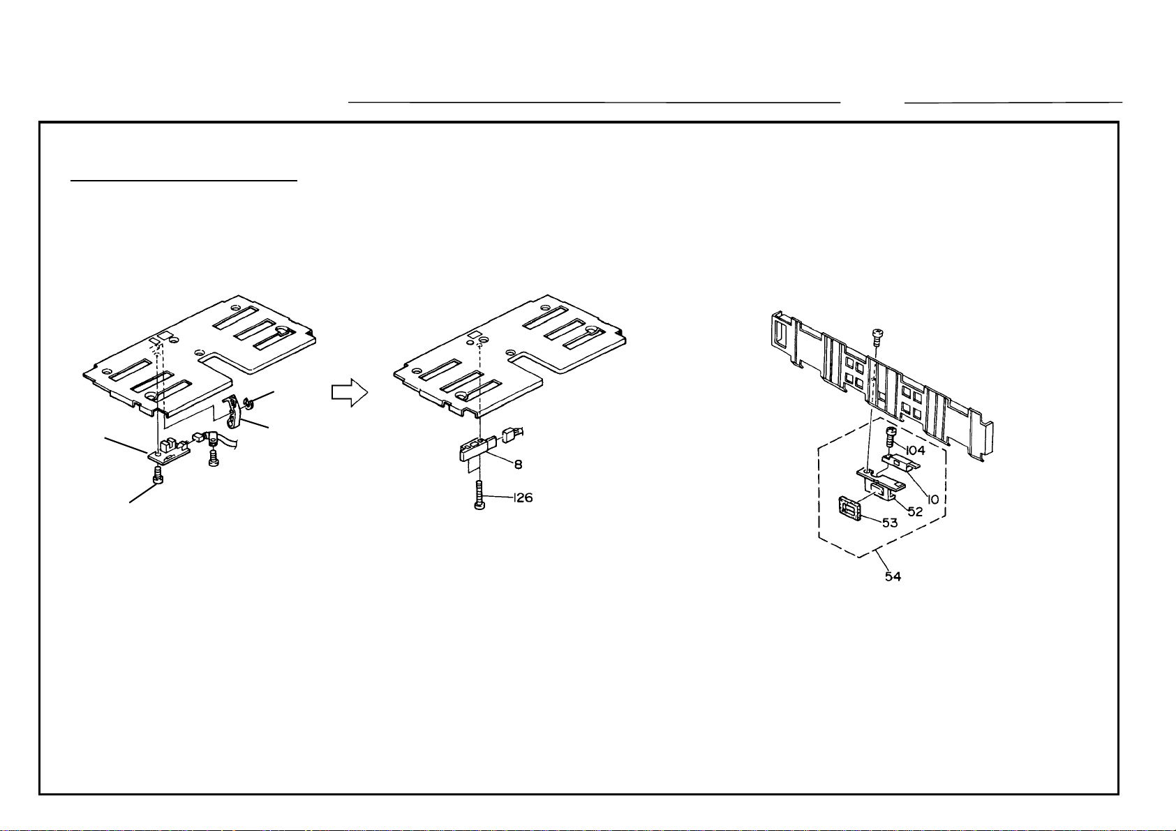
Page 17
1. Delete the following from the parts list.
Index Part Number Description
7 54462686 Paper End Feeler
2. Add the following to the parts list.
Index Part Number Description
Date of
Modification
Serial Number
126 03130120W Philips Pan Head Screw - M3 x 12
3. Correct the illustration on page 16 as shown in Drawing No. 1.
Page 51
Add the following to the part list (see Drawing No. 2):
Index Part Number Description Q’ty
54 A0284384 Separation Sensor Ass’y 1
Page 2
DETAILS OF MODIFICATION
Page 53
Correct the part number as follows:
Index Incorrect P/N Correct P/N Description
* A0283909 A0283913 Cleaning Unit
51 A0285431 A0285432 Varistor Harness
Page 57
Correct the part numbers as follows:
Index Incorrect P/N Correct P/N Description
112 05850101W 05850100B Bolt - M5 x 10
119 03150120W Philips Pan Head Screw - M5 x 12
MODIFICATION BULLETIN NO. 1 Page 2 of 8 ISSUED ON: June 30, ’92
05850121B Bolt - M5 x 12
Page 75
1. Correct the part number as follows (see Drawing No. 3):
Index Incorrect P/N Correct P/N Description
32 A0285210 A0285310 Timer Control Board
NOTE : The timer control board: A0285210 can still be used. However, as a heat sink has
been added from the first massproduction machines as shown Drawing No. 3, the
assembly part number (A0285310) only is used for this part.
Page 3
DETAILS OF MODIFICATION
2. Add the following to the parts list on page 75 and illustration on page 74 (see Drawing No. 4) :
Index Part Number Description Q’ty
93 A0285382 Lightning Surge Absorber 2
Page 77
Correct the part number as follows:
Index Incorrect P/N Correct P/N Description
31 A0287777 A0287781 Rear Cover
Page 83
Correct the part number as follows:
MODIFICATION BULLETIN NO. 1 Page 3 of 8 ISSUED ON: June 30, ’92
Index Incorrect P/N Correct P/N Description
108 09513060W Screw - M3 x 6
09513006W Philips Screw With Flat Washer - M3 x 6
Page 85
Add the following to the parts list on page 85 and illustration on page 84 (see Drawing No.5):
Index Part Number Description Q’ty
60 A0287524 Inverter Guide Plate Ass’y 1
Page 4
DETAILS OF MODIFICATION
Page 109
Correct the part number as follows (the same correction as page 75):
Index Incorrect P/N Correct P/N Description
* A0285210 A0285310 Timer Control Board
Page 112
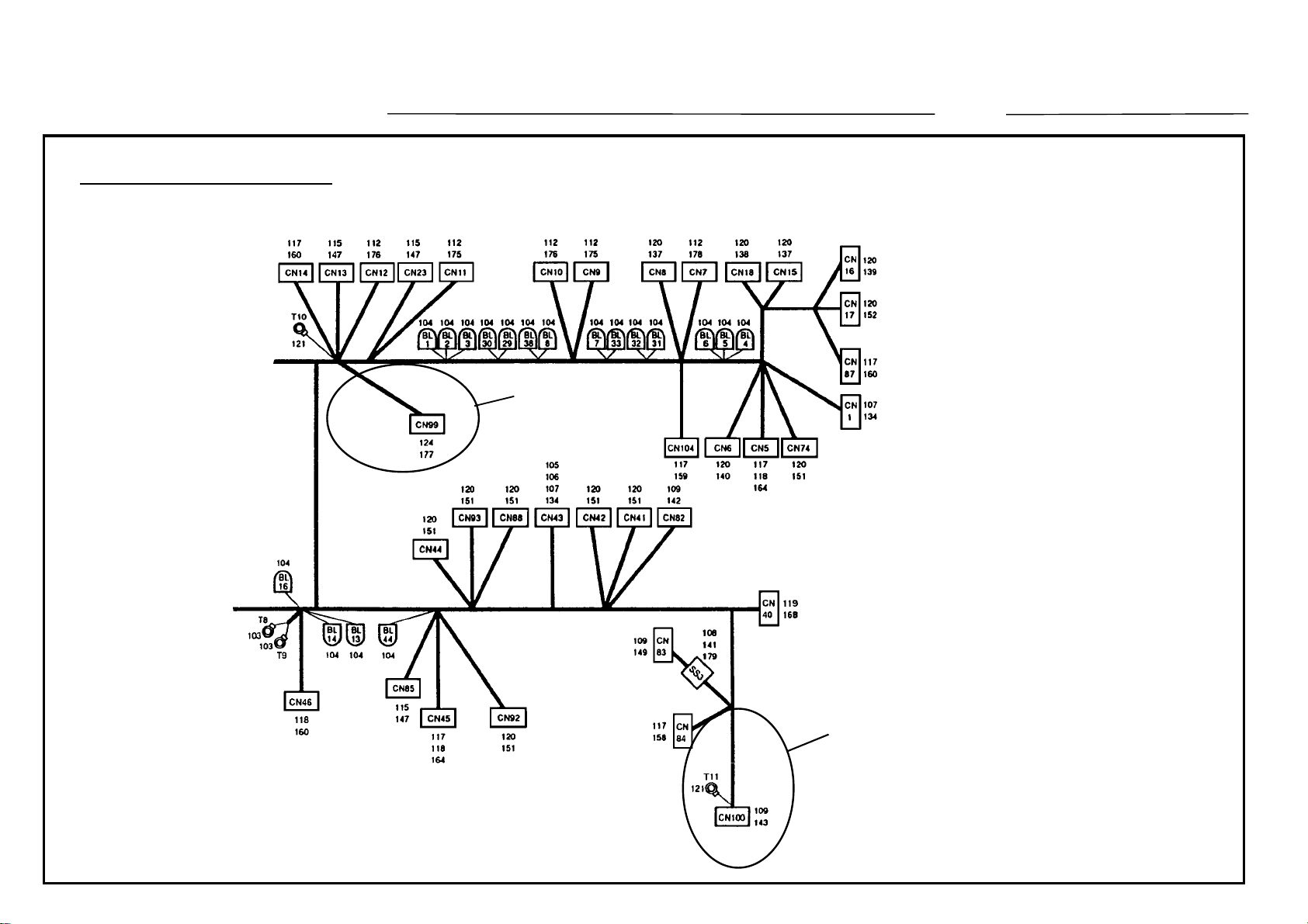
Delete CN99 and CN100 from the illustration (see Drawing No. 6).
Page 117
Correct the part number as follows:
Index Incorrect P/N Correct P/N Description
* A0285811 A0285805 Main Control Board - ADF (See NOTE 1.)
MODIFICATION BULLETIN NO. 1 Page 4 of 8 ISSUED ON: June 30, ’92
1 A0285851 A0285855 ROM - ADF (See NOTE 2.)
112 11070391 Fuse - 5A, 125V
11070752 Fuse - 5A, 250V (See NOTE 1.)
NOTE 1. To meet the safety standard, the fuse on the board has been changed (11070391 → 11070752) from the first
production machines. As a result, the part number of the ADF main control board has also been changed. (The
difference between A0285811 and A0285805 is the fuse only.)
NOTE 2. To enable the use of F4 size paper (8
1/2 x 13"), the ROM’s on the main board, operation ROM board, and paper feed
control board have been changed. (Their part numbers have not been changed. For details, refer to RTB No. 1. ) To
enable the use of the same function on the ADF (original size detection), the ROM has been changed from the March ’92
production. (5 machines of the first production use the old type ROM : A0285851.) The part number of the board is still the
same (A0285805 → A).
Page 5
DETAILS OF MODIFICATION
MODIFICATION BULLETIN NO. 1 Page 5 of 8 ISSUED ON: June 30, ’92
Drawing No. 1 (Page 16)
8
108
Drawing No. 2 (Page 50)
111
7
* New Index
Page 6
DETAILS OF MODIFICATION
MODIFICATION BULLETIN NO. 1 Page 6 of 8 ISSUED ON: June 30, ’92
Drawing No. 3 (Page 74)
Drawing No. 4 (Page 74)
139
93 * New index
139
93 * New index
Page 7
DETAILS OF MODIFICATION
Drawing No. 5 (Page 84)
MODIFICATION BULLETIN NO. 1 Page 7 of 8 ISSUED ON: June 30, ’92
60
New Index
Page 8
DETAILS OF MODIFICATION
Drawing No.6 (Page 112)
MODIFICATION BULLETIN NO. 1 Page 8 of 8 ISSUED ON: June 30, ’92
Delete
Delete
T. Ito, Manager
Copier Technical Support
Page 9
MODIFICATION BULLETIN NO. 2 Page 1 of 3 ISSUED ON: December 31, ’92
Model F5 (NRG25101) Volt/Hz
Modified Article ROMs A028-22 6202070001
Reason for
To enable the use of the sorter stapler
Modification
Date of
Modification
Serial Number
To enable the use of the sorter stapler, the ROMs on the operation ROM board and main con trol board have been changed. For
identification, the part numbe rs of the opera tion panel ass’y, Rom board, and main control board have also been changed. However,
the old ones can still be used for the sorte r version machines. (The interchangeability for the sorter version machine is O/ O. )
For details, please refer to RTB-002 issued on September 15.
Old P/N New P/N Description Interchangeability Page Index No.
AG011286 A0288800 Operation Panel Board O/O (For the sorter stapler version, X/O) 71 9
A0285242 A0288803 ROM Board O/O (For the sorter stapler version, X/O) 71 10
A0285091 A0288802 Main Control Board O/O (For the sorter stapler version, X/O)
71
93
26
*
A0285290 IC - Operation Board 1
A0288900 IC201 - M5M27C101K - 2 X/X 71 58
A0285291 IC - Operation Board 2
A0288901 IC202 - M5M27C101K - 2 X/X X/O as a set 71 59
A0285292 IC - Operation Board 3
A0288902 IC205 - M5M27C101K - 2 X/X 71 60
A0285293 IC - Operation Board 4
A0288903 IC206 - M5M27C101K - 2 X/X (Next Page) 71 61
Page 10
MODIFICATION BULLETIN NO. 2 Page 2 of 3 ISSUED ON: December 31, ’92
Old P/N New P/N Description Interchangeability Page Index No.
A0285294 IC - Operation Board 5 (Preceding Page)
A02888904 IC203 - MBM27C512-20 X/X 71 62
A0285295 IC - Operation Board 6
A0288905 IC204 - MBM27C512-20 X/X 71 63
A0285296 IC - Operation Board 7
A0288906 IC207 - MBM27C512-20 X/X X/O as a set 71 64
A0285297 IC - Operation Board 8
A0288907 IC208 - MBM27C512-20 X/X 71 65
A0285298 IC - Operation Board 9
A0288908 IC210 - MBM27C512-20 X/X 71 66
A0285299 IC - Operation Board 10
A0288909 IC211 - MBM27C512-20 X/X 71 67
A0285093 IC - Main Control 1
A0288850 IC210 - MBM27C512-20 X/X
A0285094 IC - Main Control 2
A0288851 IC198 - MBM27C512-20 X/X X/O as a set
A0285095 IC - Main Control 3
A0288852 IC205 - MBM27C512-20 X/X (Next Page)
71
93
71
93
71
93
27
1
29
2
28
3
Page 11
T. Ito, Manager
Copier Technical Support
MODIFICATION BULLETIN NO. 2 Page 3 of 3 ISSUED ON: December 31, ’92
Old P/N New P/N Description Interchangeability Page Index No.
A0285096 IC - Main Control 4 (Preceding Page)
A0288853 IC190 - MBM27C512-20 X/X
A0285097 IC - Sequence Control 1 X/O as a set
A0288854 IC123 - MBM27C512-20 X/X
A0285298 IC - Sequence Control 2
A0288855 IC124 - MBM27C512-20 X/X
71
93
71
93
71
93
30
4
31
5
32
6
Page 12
T. Ito, Manager
Copier Technical Support
MODIFICATION BULLETIN NO. 3 Page 1 of 1 ISSUED ON: December 31, ’92
Model F5 (NRG25101) Volt/Hz
Modified Article Noise Filter A028-22
Reason for
Due to vendor change
Modification
Due to vendor change, the following parts has been changed.
Old P/N New P/N Description Interchangeability Page Index No.
16020946 Noise Filter - 220V/240V
16027075 Noise Filter - RG208F O/O 75 136
Date of
Modification
Serial Number
Page 13
NOTE
MODIFICATION BULLETIN NO. 4 PAGE 1 OF 27
ISSUED ON: July15, ’93
Model F5 (Gestetener 25101 / Nashuatec 53101) Volt/Hz
Modified Article Parts Catalog A028-22
Reason for
F5 Finisher Version (Nashuatec 53101) Information
Modification
A112-22
A new version machine for the F5 has bee n adde d (A1 12 -22 : F5 Finish er Ve rsion ).
1. Add the following parts unique to the finisher version to your parts cat alo g:
Parts Catalog
Part Number Description Q’ty Used
Page Index No.
11 2 A1121409 Left Door 1 A0281407 —
11 76 AA012055 Dust Filter 1 → 2 Fig.1
11 78 A0281637 Optics Filter Cover 1 → 2 Fig.1
A028-22 Unique Part (P/N)
(Description)
Date of
Modification
Fig. NO.
Serial Number
6203030001
(First
Mass-production)
1) The left door is different because of the model name logotype.
2) The dust filter is replaces with th e Air Filte r (Ind ec # 38 , Page 73, Part Numbe r AA0 12 017) to allow
the installation of the new cleaning roller cooling pump unit.
3) One set of the dust filter an d op tics filt er cover is used in the sorter version machine, but both sets
are used for the finishe r ve rsion ma chine.
2. Add the following part uniq ue to th e fin isher version machine. For the sorter versio n mach ine , two Rear Upper
Support Plates - ADF (Index # 20, Page 15, Pa rt Numb er A0 28 1193 ) are used, and the upper one is replaced with
# A1121193 on the finisher version mach ine , to allow th e installation of the new cleanin g rolle r cooling pump unit.
Parts Catalog
Part Number Description Q’ty Used Fig. No.
Page Index No.
15 * 49 A1121193 Left Side Support Plate 1 Fig 2
*
Page 14

MODIFICATION BULLETIN NO. 4 PAGE 2 OF 27
3. Add the following parts unique to the finisher version machine.
Parts Catalog
Page Index No.
39 * A1122510 OPC Unit 1 A0282500
41 35 A0285306 DC Motor - DC24V 1 A0285307
69
73
71 9 A1121450 Operation Panel Unit 1
71 10 A1125070 Operation ROM Board 1
71
93
71
93
71
93
71
93
71
93
16
41
26
*
27
1
28
3
29
2
30
4
Part Number Description Q’ty Used
A1124095 Pump Tube 1 A0284088
A1125041 Main Control Board 1 A0288802 FIg. 9
A1125102 IC210 - HN27C101AG-17 1
A1125104 IC205 - HN27C101AG-17 1
A1125103 IC198 - HN27C101AG-17 1
A1125105 IC190 - HN27C101AG-17 1
A028-22 Unique Part (P/N)
A0288800
(Operation Panel Board)
A0288803
(ROM Board)
A0288850
(IC210 - MBM27C512-20)
A0288852
(IC205 - MBM27C512-20)
A0288851
(IC198 - MBM27C512-20)
A0288853
(IC190 - MBM27C512-20)
(Description)
Fig. NO.
71
93
71
93
71
73
113
71
73
115
31
5
32
6
33
1
34
2
A1125108 IC123 - MBM27C512-20 1 A0288854
A1125109 IC124 - MBM27C512-20 1 A0288855
A1125400 DC Harness 1 A0285403 Fig. 10
*
A1125500 AC Harness 1 A0285503 Fig. 11
*
Page 15

MODIFICATION BULLETIN NO. 4 PAGE 3 OF 27
ISSUED ON: July15, ’93
Parts Catalog
Page Index No.
71 58 A1125205 IC201 - M5M27C101K-2 1 A0288900
71 59 A1125206 IC202 - M5M27C101K-2 1 A0288901
71 60 A1125207 IC205 - M5M27C101K-2 1 A0288902
71 61 A1125208 IC206 - M5M27C101K-2 1 A0288903
71 62 A1125209 IC203 - MBM27C512-20 1 A0288904
71 63 A1125210 IC204 - MBM27C512-20 1 A0288905
71 64 A1125211 IC207 - MBM27C512-20 1 A0288906
71 65 A1125212 IC208 - MBM27C512-20 1 A0288907
71 66 A1125213 IC210 - MBM27C512-20 1 A0288908
71 67 A1125214 IC211 - MBM27C512-20 1 A0288909
NOTE:
1) The OPC unit is different because th e OP C drive motor (DC Motor - DC24V, # A0285306), which sat isfie s the
Part Number Description Q’ty Used
German electromagnet ic field interference standards (VDE 24 3), is used in the finisher version.
2) The pump tube is different due to the new cleaning roller cooling pump unit. The pump unit has been changed
to meet VDE 243 standards (see fig. 4).
A028-22 Unique Part (P/N)
(Description)
Fig. No.
3) The operation panel unit is differen t du e to the new EPROM’s on the ope rat ion RO M board.
4) The main control board was newly designed to allo w the insta llation of the 4 one-megabyte EPROM’s.
5) The DC and AC main harness are different to allow the installa tio n of the optional key counter an d prin ter
connector unit, and to meet the new ac power dist ribution for approval by VDE 243. The thre e circuit brea kers
used for each phase of the ac 3-phase power distribution have been changed to three choke coils (see fig. 4
and 6).
Page 16

MODIFICATION BULLETIN NO. 4 PAGE 4 OF 27
4. Add the following pa rts un iqu e to the finisher version machine.
ISSUED ON: July15, ’93
Parts Catalog
Page Index No.
73 * A1124085 Cleaning Cooling Pump Ass’y 1 Fig.3
73 * 71 AZ020004 Coil - 750MH 15A 1 Fig. 3
73 * 72 AZ020005 Coil - 4MH 10A 1 Fig. 3
73 * 73 A1124087 Shielding Sheet 1 Fig. 3
73 * 74 A1124093 Pump Bracket 1 Fig. 3
73 * 75 A1124095 Pump Tube 1 Fig. 3
73 * 76 A1124098 Pump Tube Elbow 1 Fig. 3
73 * 77 A1124091 Coil Bracket 1 Fig. 3
73 * 78 A1124092 Shielding Sheet 1 Fig. 3
73 101 03140060W
73 111 11050196 Harness Clamp 1 Fig. 3
73 * 123 08000094 Philips Screw - M3 x 16 2 Fig. 3
73 * 124 09514006W
Part Number Description Q’ty Used Fig. No.
Philips Pan Head Screw - M4 x
6
Philips Screw With Flat Washer
- M4 x 6
9 Fig. 3
4 Fig. 3
73 * 125 11050011 Nylon Clip - 8N 1 Fig. 3
* : New Index No.
Page 17
MODIFICATION BULLETIN NO. 4 PAGE 5 OF 27
NOTE: The following are parts uniqu e to the sorter version machine. (Info rmat ion only)
ISSUED ON: July15, ’93
Parts Catalog
Page Index No.
73 36 AA151272 Seal - 6 x 81 x 84 1 Fig. 4
73 37 A0284076 Filter Holder 1 Fig. 4
73 38 AA012017 Air Filter 1 Fig. 4
73 39 A0284070 Pump Bracket 1 Fig. 4
73 41 A0284088 Pump Tube 1 Fig. 4
73 42 A0284080 Pump Duct 1 Fig. 4
73 101 03140060W Philips Pan Head Screw - M4 x 6 4 Fig. 4
73 104 03130300W Philips Pan Head Screw - M3 x 30 2 Fig. 4
73 114 09514010W
Part Number Description Q’ty Used Fig. No.
Philips Screw With Flat Washer
- M4 x 10
2 Fig. 4
Page 18
MODIFICATION BULLETIN NO. 4 PAGE 6 OF 27
5. Add the following pa rts un iqu e to the finisher version machine.
ISSUED ON: July15, ’93
Parts Catalog
Page Index No.
75 * 94 AZ020004 Coil - 750MH 15A 1 Fig. 5
75 * 95 A1125510 Power Supply Unit Harness - B 1 Fig. 5
75 * 96 A1125520 Power Supply Unit Harness - C 1 Fig. 5
75 * 97 A1125601 Power Supply Unit Bracket 1 Fig. 5
75 101 03140060W Philips Pan Head Screw - M4 x 6 6 Fig. 5
75 * 144 03140040W Philips Pan Head Screw - M4 x 4 6 Fig. 5
75 * 145 11070781 Circuit Bracket - 250V / 15A 1 Fig. 5
Part Number Description Q’ty Used Fig. No.
NOTE: The following are parts unique to the sorter version mach ine. (Information only)
Parts Catalog
Page Index No.
75 58 A0285628 Power Supply Unit Bracket 1 Fig. 6
75 87 A0285532 Power Supply Unit Harness-B 1 Fig. 6
75 88 A0285533 Power Supply Unit Harness-C 1 Fig. 6
Part Number Description Q’ty Used Fig. No.
75 127 03140120W Philips Pan Head Screw - M4 x 12 10 Fig. 6
75 129 11070264 Circuit Breaker - 8A 1 Fig. 6
75 130 11070468 Circuit Breaker - 2-5000 5A / 250V 1 Fig. 6
75 131 11070469 Circuit Breaker - 250V 10A 2 Fig. 6
75 132 11070470 Circuit Breaker - 15A / 250V 1 Fig. 6
Page 19
ISSUED ON: July15, ’93
MODIFICATION BULLETIN NO. 4 PAGE 7 OF 27
6. Add the following parts unique to the finisher version machine.
Parts Catalog
Page Index No.
79 4 A1125841 Connector Harness 1
79
117
83 5 59365501 Transport Drive Motor - DC 21W 3
117 1 A1125855 EPROM - MBM27C128-30 1 A0285855
NOTE:
1) The connector harness is different to allow the operation of the new recycle arm solen oid .
30
*
Part Number Description Q’ty Used
A1125805 Main Control Board - ADF 1
2) The ADF main control board is different due to the new EPROM on the board.
A028-22 Unique Part (P/N)
(Description)
A0285841
(Harness - Relay Board)
A0285805
(ADF Control Board)
AX060027
(Drive Motor - DC24V / 21W)
Fig. No.
Fig. 7
Page 20
MODIFICATION BULLETIN NO. 4 PAGE 8 OF 27
7. Add the following parts unique to the finisher version machine.
ISSUED ON: July15, ’93
Parts Catalog
Page Index No.
81 * 76 A1127881 Solenoid Bracket 1 Fig. 8
81 * 77 A1127885 Solenoid Spring 1 Fig. 8
81 * 78 A1127886 Recycle Arm Solenoid Ass’y 1 Fig. 8
81 * 79 A1127919 Nozzle Upper Casing 1 Fig. 8
81 * 119 07010060G Flat Washer - M6 1 Fig. 8
81 * 120 07010040G Flat Washer - M4 2 Fig. 8
Part Number Description Q’ty Used Fig. No.
* : New Index No.
NOTE: The following are parts uniqu e to the sorter version machine. (Information only)
Parts Catalog
Page Index No.
81 7 A0287919 Nozzle Upper Casing 1 Fig. 8
81 10 A0287883 Pressure Lever 1 Fig. 8
81 11 A0287885 Solenoid Spring 1 Fig. 8
Part Number Description Q’ty Used Fig. No.
81 14 A0287886 Recycle Arm Solenoid Ass’y 1 Fig. 8
81 15 A0287881 Solenoid Bracket 1 Fig. 8
81 17 A0287970 Spring - Separation Plate 1 Fig. 8
Page 21

MODIFICATION BULLETIN NO. 4 PAGE 9 OF 27
ISSUED ON: July15, ’93
8. Add the following to page 93 "41. MA IN CONTRO L BO ARD" as parts unique to the finisher
version machine (see fig. 9 for th e referrence illustration).
Index P/N Description Q’ty Index P/N Description Q’ty
* A1125041 Main Control Board 1
1 A1125102 IC 210 - HN27C101AG-17 1
2 A1125103 IC 198 - HN27C101AG-17 1
3 A1125104 IC 205 - HN27C101AG-17 1
4 A1125105 IC 190 - HN27C101AG-17 1
5 A1125108 IC 123 - MBM27C512-20 1
6 A1125109 IC 124 - MBM27C512-20 1
101 11001093 Connector - 6P
102 11010328 Connector Pin Contact
103 11022484 Connector
104 11024053 Connector - 1P
105 11030428 Connector - 20P
106 11030648 Connector - 60P
107 11030649 Connector - 50P
108 11030653 Connector - 34P
109 11030655 Connector - 16P
110 11031022 Connector - 5P
111 11031889 Connector - 6P
112 11040588 DIP Socket - 28P
113 11040589 DIP Socket : 32P
114 11021436 Dip Switchi
115 12060046 Battery - BR-2/3AE
116 14000418 Capacitor - FA1
117 14000492 Transistor - 2SA1461-Y24
118 14000493 Transistor - 2SC3734-B24
119 14010835 Diode - 1SS190
120 14020593 Zener Diode - RD6.2P
121 14020643 Zener Diode - RD3.3M-B1
122 14020711 Zener Diode - RD4.7MB3
123 14020852 Zener Diode - RD15P 15V 1W
124 14030416 LED - Red
125 14030499 LED - Yellow
126 14030500 LED - Green
127 14071597 IC - SN74LS10NS
128 14071600 IC - SN74LS244NS
129 14071605 TTL - SN74LS157NS
130 14071740 IC - SN74LS27NS
131 14071741 TTLIC - SN74LS32NS
132 14071745 IC - SN74LS139NS
133 14071783 IC - SN74LS02NS
134 14071880 IC - SN74LS04NS
135 14071882 IC - SN74LS373NS
136 14071883 IC - TC4050BF
137 14071925 IC - SN15189ANS
138 14071926 IC - SN75188NS
139 14072051 IC - SN74LS00NS
140 14072052 IC - NS74LS74ANS
141 14072055 IC - TD62304F
142 14072077 IC - SN74LS138NS
143 14072081 IC - SN74LS08NS
144 14072187 IC - SN74LS07NS
145 14072253 IC - SN74LS393NS
146 14072468 IC - TC5565AFL-15L
147 14072767 IC - MB89254-PF
148 14072796 IC - TC4584BF
149 14072797 IC - TC5564AFL-15
Page 22

MODIFICATION BULLETIN NO. 4 PAGE 10 OF 27
ISSUED ON: July15, ’93
Index P/N Description Q’ty Index P/N Description Q’ty
150 14072798 SRAM - MB8421-90LF
151 14072799 IC - MBL8086-2
152 14072800 IC - MB89255A
153 14072801 LSI - MB89251A
154 14072803 IC - MB89284A
155 14072804 TTL - SN74LS122NS
156 14072805 IC - SN74LS03NS
157 14072807 IC - RTC-62421
158 14072825 IC - TD62384F
159 14072933 IC - MB89259A-PF
160 14080611 IC - MB3771PF
161 14080701 IC - TL331CPS
162 14080702 IC - TL431CPS
163 14080704 IC - ADC0808CCN
164 14080945 IC - LM324ANS
165 15030195 Oscillator - 24MHz
166 15030202 IC - JCK1100MC
167 16011871 Resistor - 220 Ohm 1/4W +-1%
168 16011872 Resistor - 240 Ohm 1/4W +-1%
169 16011873 Resistor - 270 Ohm 1/4W +-1%
170 16011874 Resistor - 360 Ohm 1/4W +-1%
171 16011875 Resistor - 820 Ohm 1/4W +-1%
172 16013928 Resistor - 26K Ohm 1/8W +-1%
173 16015188 Resistor - 100K Ohm 1/8W +-1%
174 16018476 Resistor - 2K Ohm 1/2W
175 16027007 Capacitor 0.001UF 12V
176 16041367 Capacitor - 100uF +-20% 25V
177 16042017 Capacitor - 10uF 10V +-20%
178 16042018 Capacitor - 4.7mF 10V +-20%
179 16042019 Capacitor - 0.68uF +-20%
180 16050211 Capacitor - 47000PF -20 +80%
181 16050359 Capacitor - 22pF 50V
182 16050362 Capacitor - GRM40B103J50
183 16050513 Capacitor - 2200pF 50V +80% -20%
184 16050517 Capacitor - 330pF +80 -20% 50V
185 16050636 Capasitor - 0.1MF
186 16100656 Resistor - 9.1K Ohm 1/8W +-5%
187 16100660 Resistor - 62K Ohm 1/8W +-5%
188 16100889 Resistor - 4.7K Ohm 1/16W +-5%
189 16100890 Resistor - 160 Ohm +-5% 1/8W
190 16100891 Resistor - 270 Ohm 1/8W +-5%
191 16100892 Resistor - 1K Ohm 1/8W +-5%
192 16100893 Resistor - 3.9K Ohm 1/8W +-5%
193 16100894 Resistor - 5.6K Ohm 1/8W +-5%
194 16100895 Resistor - 8.2K Ohm 1/8W +-5%
195 16100896 Resistor - 10K Ohm 1/8W +-5%
196 16100897 Resistor - 390K Ohm 1/8W +-5%
197 16100898 Resistor - 150 Ohm 1/8W +-5%
198 16100899 Resistor - 82 Ohm 1/8W +-5%
199 16100902 Resistor - 100K Ohm 1/8W +-5%
200 16100903 Resistor - 4.7K Ohm 1/8W +-5%
201 16114101 Resistor - 100 Ohm 1/4T +-5%
202 16114181 Resistor - 180 Ohm 1/4T +-5%
203 16114471 Resistor - 470 Ohm 1/4T +-5%
204 16221501 Resistor - 1.5k Ohm 1/4T +-1%
205 16224701 Resistor - 4.7k Ohm +-1% 1/4W
206 16302560 Resistor - 56 Ohm +5% 1/8W
Page 23

MODIFICATION BULLETIN NO. 4 PAGE 11 OF 27
ISSUED ON: July15, ’93
9. Add the following to page 113 " 50 DC MAIN HARNESS " as parts un iqu e to the finisher version machine (see fig . 10 for th e
referrence illustration).
Index P/N Description Q’ty Index P/N Description Q’ty
* A1125400 DC Harness 1
1 54085160 Short Connector 1
101 11000340 Connector - 1P
102 11000350 Closed Terminal
103 11000503 Socket - Mate-N-Lock
104 11000844 Socket - Mate-N-Lock
105 11000853 Closed Terminal
106 11001041 Pin - Mate-N-Lock
107 11001043 Pin - Mate-N-Lock
108 11001061 Pin - Mate-N-Lock
109 11001155 Contact
110 11001159 Socket - Mate-N-Lock
111 11001172 Fastening Recept acle
112 11001181 Socket - Mate-N-Lok
113 11001182 Socket - Mate-N-Lock
114 11001187 Pin - Mate-N-Lok
115 11001188 Pin - Mate-N-Lok
116 11001190 Socket - Mate-N-Lock
117 11001239 Pin - Mate-N-Lock
118 11001240 Socket - Mate-N-Lock
119 11001241 Socket - Mate-N-Lock
120 11001254 Socket - Mate-N-Lock
121 11001259 Socket - Mate-N-Lock
122 11001264 Wire Terminal
123 11001270 Fastening Recept acle
124 11001271 Fastening Recept acle
125 11001326 Socket - Mate-N-Lock
126 11001342 Terminal
127 11001345 Pin Contact
128 11001346 Pin Contact
129 11001396 Connector - 1P
130 11001402 Connector - 14-16P
131 11001499 Connector - 1P
132 11001505 Connector - 1P
133 11001506 Connector - 1P
134 11020185 Connector - 4P
135 11020984 Connector - 2P
136 11020989 Connector - 9P
137 11021089 Connector - 3P
138 11021090 Connector - 4P
139 11021091 Connector - 6P
140 11021093 Connector - 10P
141 11021094 Connector - 12P
142 11021178 Connector - 5P
143 11021286 Connector - 2P
144 11021306 Connector - 3P
145 11021322 Connector - 20P
146 11021323 Connector - 30P
147 11021344 Connector - QP - 16XS - C
148 11021375 Connector - 4P
149 11021376 Connector - 6P
150 11021397 Connector - 2P
151 11021398 Connector - 2P
152 11021412 Connector - 2P
153 11021418 Connector - 8P
154 11021419 Connector - 2P
Page 24

MODIFICATION BULLETIN NO. 4 PAGE 12 OF 27
Index P/N Description Q’ty
155 11021507 Connector - 2P
156 11021508 Connector - 3P
157 11021509 Connector - 4P
158 11021511 Connector - 9P
159 11021515 Connector - 2P
160 11021516 Connector - 3P
161 11021517 Connector - 4P
162 11021518 Connector - 6P
163 11021519 Connector - 9P
164 11021520 Connector - 12P
165 11021521 Connector - 15P
166 11021526 Connector - 4P
167 11021563 Connector - 12P
168 11021715 Connector - 26P
169 11021731 Connector - 20P
170 11021740 Connector - 7P
171 11021983 Connector - 3P
172 11022103 Connector - 1P
173 11023762 Connector - 4P
174 11024055 Connector - 24P
175 11024185 Connector - 26P
176 11030656 Connector - 16P
177 11030657 Connector - 50P
178 11030661 Connector
179 11030663 Connector - 16P
180 14020110 Diode - V06C
181 14020471 Zener Diode - Z1015
ISSUED ON: July15, ’93
Page 25

MODIFICATION BULLETIN NO. 4 PAGE 13 OF 27
ISSUED ON: July15, ’93
ISSUED ON: July15, ’93
10. Add the following to page 115 " 51 AC MAIN HARNES S" as part s uniq ue to th e fin isher version machine (see fig. 11 for the
referrence illustration).
Index P/N Description Q’ty Index P/N Description Q’ty
* A1125500 AC Harness 1
101 11000051 Wire Terminal
102 11000270 Fastening Recepta cle
103 11000350 Closed Terminal
104 11000853 Closed Terminal
105 11000916 Connector - 2P
106 11001041 Pin - Mate-N-Lock
107 11001042 Socket - Mate-N-Lock
108 11001043 Pin - Mate-N-Lock
109 11001061 Pin - Mate-N-Lock
110 11001062 Socket - Mate-N-Lock
111 11001171 Fastening Recepta cle
112 11001181 Socket - Mate-N-Lok
113 11001190 Socket - Mate-N-Lock
114 11001238 Pin - Mate-N-Lock
115 11001239 Pin - Mate-N-Lock
116 11001240 Socket - Mate-N-Lock
117 11001241 Socket - Mate-N-Lock
118 11001249 Receptacle Terminal
119 11001259 Socket - Mate-N-Lock
120 11001264 Wire Terminal
121 11001327 Contact
122 11001341 Pin Contact
123 11001345 Pin Contact
124 11001491 Pin Contact - 1P
125 11020512 Connector - 3P
126 11020782 Connector - 4P
127 11020983 Connector - 2P
128 11020987 Connector - 6P
129 11020991 Connector - 12P
130 11020992 Connector - 12P
131 11021005 Connector - 1P
132 11021006 Pin Housing - 1P
133 11021089 Connector - 3P
134 11021323 Connector - 30P
135 11021373 Connector - 3P
136 11021377 Connector - 5265 - 7P
137 11021401 Receptacle Housing - 1P
138 11021402 Receptacle Housing - 1P
139 11021403 Receptacle Housing
140 11021404 Connector - 1P
141 11021506 Connector - 1P
142 11021507 Connector - 2P
143 11021508 Connector - 3P
144 11021510 Connector - 6P
145 11021511 Connector - 9P
146 11021515 Connector - 2P
147 11021516 Connector - 3P
148 11021518 Connector - 6P
149 11021519 Connector - 9P
150 11021520 Connector - 12P
151 11021521 Connector - 15P
152 11021715 Connector - 26P
153 11021918 Connector - 10P
154 11022101 Connector - 1P
Page 26
MODIFICATION BULLETIN NO. 4 PAGE 14 OF 27
Fig. 1 1. EXTERIOR
* 76
* 78
ISSUED ON: July15, ’93
* : Part unique to the finisher version
76
78
Page 27
MODIFICATION BULLETIN NO. 4 PAGE 15 OF 27
* 49
Fig. 2 3. FRAME SECTION 2
# 20
ISSUED ON: July15, ’93
# : Part unique to the sorte r ve rsion
* : Part unique to the finishe r ve rsion
Page 28
MODIFICATION BULLETIN NO. 4 PAGE 16 OF 27
# 101
Fig. 3 32. ELECTRICAL SECTION 2 (Finisher Version Unique Parts)
* 124
ISSUED ON: July15, ’93
# 101
* 72
# 101
* 71
* 125
# 111
* 74
* 77
* 73
* 78
Old
* 76
* 75
* 75
* 76
# 101
* 123
Page 29
MODIFICATION BULLETIN NO. 4 PAGE 17 OF 27
Fig. 4 32. ELECTRICAL SECTION 2 (Sorter Version Unique Parts)
# 41
# 39
ISSUED ON: July15, ’93
# 114
# 104
# 38
# 36
# 42
# 101
# 37
# : Part unique to the sorte r ve rsion
Page 30
MODIFICATION BULLETIN NO. 4 PAGE 18 OF 27
* 95
Fig. 5 33. ELECTRICAL SECTION 3
(Finisher Version Unique Parts)
ISSUED ON: July15, ’93
# 101
* 96
* 145
* 94
* 97
* 144
# : Part unique to the finish er versio n
* : Part unique to the finishe r ve rsion , bu t
used elsewhere in the sort er versio n
Page 31

MODIFICATION BULLETIN NO. 4 PAGE 19 OF 27
Fig. 6 33. ELECTRICAL SECTION 3 (Sorter Version Unique Parts)
# 87
ISSUED ON: July15, ’93
# 88
# 132
# 131
# 130
# 129
# 131
# 58
# 127
# 127
Page 32

T. Ito, Manager
Copier Technical Support
MODIFICATION BULLETIN NO. 4 PAGE 20 OF 27
Fig. 7 35. ADF FRAME AND ELECTRICAL SECTION
ISSUED ON: July15, ’93
Sorter Version
Finisher Version
4 (Connector Harness)
Sorter Version
Finisher Version
Page 33

MODIFICATION BULLETIN NO. 4 PAGE 21 OF 27
* 78
Fig. 8 36. ADF FEED SECTION
( # 14)
# 14
ISSUED ON: July15, ’93
( * 78)
# 17
# 11
# 10
# 7
# 15
* 77
# 7
* 119
* 120
* 76
* 79
* 79
# : Part unique to the sorte r version
* : Part unique to the finishe r ve rsion
Page 34

MODIFICATION BULLETIN NO. 4 PAGE 22 OF 27
Fig. 9 41. MAIN COTROL BOARD (A112) 1/4
ISSUED ON: July15, ’93
Page 35

MODIFICATION BULLETIN NO. 4 PAGE 23 OF 27
Fig. 9 41. MAIN COTROL BOARD (A112) 2/4
ISSUED ON: July15, ’93
Page 36

MODIFICATION BULLETIN NO. 4 PAGE 24 OF 27
Fig. 9 41. MAIN COTROL BOARD (A112) 3/4
ISSUED ON: July15, ’93
Page 37

MODIFICATION BULLETIN NO. 4 PAGE 25 OF 27
Fig. 9 41. MAIN COTROL BOARD (A112) 4/4
ISSUED ON: July15, ’93
Page 38

MODIFICATION BULLETIN NO. 4 PAGE 26 OF 27
Fig. 10 50. DC MAIN HARNESS (A112)
ISSUED ON: July15, ’93
Page 39

MODIFICATION BULLETIN NO. 4 PAGE 27 OF 27
T. Ito, Manager
Copier Technical Support
Fig. 11 51. AC MAIN HARNESS (A112)
ISSUED ON: July15, ’93
Page 40

MODIFICATION BULLETIN NO. 5 PAGE 1 OF 3
ISSUED ON: July 15, ’93
Model F5 (Gestetner 25101 / Nashuatec 53101) Volt/Hz
Modified Article Printer Interface Board etc. A028-22
Draw
No.
Reason for
Modification
Old Parts
No.
To enable the use of the printer for servicing
(Nashuatec 53101 only)
New Parts
No.
A1125060 Printer Interface Board 0 → 1 * 11 125
A1127110 PCB Holder 0 → 1 * 12 125
A1127120
A5315420 Printer Harness 0 → 1 * 14 125
11024039 Connector Joint Stud 0 → 2 * 101 125
11050193 Nylon Stud 0 → 4 * 102 125
Description Rank
Printer Harness Main / Interface
Q’ty Used
Old→New
0 → 1 * 13 125
Inter-
change-
ability
Parts needed for replacement by new part
Part No. Description No. Page
Date of
Modification
A112-22 6203060001
Serial
Number
Parts
Catalog
* : New Index No.
Rank: A : Replace with new parts immediately. B : Replace with new parts at time of repair. C : Replace with new parts at time of overhaul.
Interchangeability:
(1) When old and new parts are not mutually interchangeable, use additional parts or an assembly part as indicated in "Parts needed for
replacement by new part" to install the new part.
(2) The mark to the left of the slash indicates whether the old part can be used in the new machine, and the mark to the right indicates whether
the new part can be used in the old machine. x = Not interchangeable o = Interchangeable
Page 41

CAUTION:
MODIFICATION BULLETIN NO. 5 PAGE 2 OF 3
ISSUED ON: July 15, ’93
MODIFICATION DETAILS
To facilitate servicing, the part s describ ed in the previo us page have been adde d as acce ssories. By using those parts,
service tool number 6 " Print Out " can be used, eve n whe n th e optio na l print er connector unit is not installed. The part s
can be set as follows:
1. Fully open the front door to access the main control board.
2. Disconnect CN101 on the main control board. Then, connect the two harne sses an d prin ter interface board
as shown in the illustration in the following page.
1. Never disconnect CN101 before turning off the main switch.
2. Bind the grounding wire [A] wit h vinyl tape to avoid po ssible dama ge to PCB ’s. The grou nd ing wire is
necessary when the harness is used with th e op tio na l print er connector.
3. The bottom of the PCB holder is a permanent magnet. Stick it on the copier left cover befo re tu rnin g on the
main switch to avoid possible damag e to PCB’s.
3. Connect the printer. (For the printer, refe r to RTB No. 5.)
4. Turn on the main switch and access service to ol nu mbe r 6 " Print Out ". Then, pre ss t he app rop r iat e key.
NOTE: The printer inte rfa ce bo ard (#A1 12 5060 ), prin ter harness (#A5315420), and two con ne cto r joint studs (2 x
#11024039) have been removed fro m the optional printer connector unit (fro m the first mass-p rod uction) then
included in the copier accessories. Those parts are used when th e op tional printer connector unit is installed.
Keep them for each machine for future use.
Page 42

T. Ito, Manager
Copier Technical Support
MODIFICATION BULLETIN NO. 5 PAGE 3 OF 3
102
[A]
ISSUED ON: July 15, ’93
13
14
11, 12,
102
101
11
102
12
Page 43

MODIFICATION BULLETIN NO. 6 PAGE 1 OF 2
ISSUED ON: February 15, ’94
Model F5 (Gestetner 25101 / nashuatec 53101) Volt/Hz
Modified Article Side Plate - First Tray A028-22
Reason for
To allow the use of thick paper in the first tray
Modification
Draw
No.
Old Parts
No.
A0282823 Side Fence
New Parts
No.
A0282848 Side Plate - First Tray
Description
Rank
Q’ty Used
Old→New
1 → 0
0 → 1
Inter-
change-
ability
X/O 4 17
Parts needed for replacement by new part
Part No. Description No. Page
Date of
Modification
A112-22 6203080001
Serial
Number
Service parts
only
Parts
Catalog
Rank: A : Replace with new parts immediately. B : Replace with new parts at time of repair. C : Replace with new parts at time of overhaul.
Interchangeability:
(1) When old and new parts are not mutually interchangeable, use additional parts or an assembly part as indicated in "Parts needed for
replacement by new part" to install the new part.
(2) The mark to the left of the slash indicates whether the old part can be used in the new machine, and the mark to the right indicates whether
the new part can be used in the old machine. x = Not interchangeable o = Interchangeable
Page 44

MODIFICATION BULLETIN NO. 6 PAGE 2 OF 2
ISSUED ON: February 15, ’94
DETAILS OF MODIFICATION
It was found that the paper leading edge hit s the side pla te and a paper misfe ed may occur whe n 170 g/ m m
2
paper is used in the first tray. Although 160 g/mm2 paper can be fed from the first tray without any problem (the
maximum paper weight specification is 163 g/mm2), the configuration of the side plate has been changed as
shown below to allow the use of thicker paper.
51.8mm
3.5mm
51mm
4.5mm
4
(Side Plate - First Tray)
S. Hamano, Assistant General Manager
Technical Support Department
Page 45

MODIFICATION BULLETIN NO. 7 PAGE 1 OF 2
ISSUED ON: February 15, ’94
Model F5 (Gestetner 25101 / nashuatec 53101) Volt/Hz
Modified Article Manual Feed Exit Roller A028-22
Reason for
To prevent the roller from generating sponge dust
Modification
Draw
No.
Old Parts
No.
A0287997 A1127997 Manual Feed Exit Roller
New Parts
No.
Description
Rank
Q’ty Used
Old→New
2 → 2
Inter-
change-
ability
O/O 50 85
Parts needed for replacement by new part
Part No. Description No. Page
Date of
Modification
A112-22 6203060001
Serial
Number
Service parts
only
Parts
Catalog
Rank: A : Replace with new parts immediately. B : Replace with new parts at time of repair. C : Replace with new parts at time of overhaul.
Interchangeability:
(1) When old and new parts are not mutually interchangeable, use additional parts or an assembly part as indicated in "Parts needed for
replacement by new part" to install the new part.
(2) The mark to the left of the slash indicates whether the old part can be used in the new machine, and the mark to the right indicates whether
the new part can be used in the old machine. x = Not interchangeable o = Interchangeable
Page 46

MODIFICATION BULLETIN NO. 7 PAGE 2 OF 2
ISSUED ON: February 15, ’94
DETAILS OF MODIFICATION
To prevent the manual fee d exit rollers (spo ng e like mat erial) from being rubbed against the exterior cover and
generating sponge dust (alth ou gh there is n o problem with roller faunction), the diameter of the roller has been
reduced by 1mm as shown below. This allows for a 0.5mm gap between the roller and exterior cover. Origina ls can
still be transported properly.
OLD
27mm
(Manual Feed Exit Roller)
NEW
26mm
0.5mm
50
S. Hamano, Assistant General Man ag er
Technical Support Department
Page 47

MODIFICATION BULLETIN NO. 8 PAGE 1 OF 1
ISSUED ON: February 15, ’94
Model F5 (Gestetner 25101 / nashuatec 53101) Volt/Hz
Modified Article DC Motor - DC24V (Tracking Motor) A028-22
Reason for
Due to part standardization (Sorter version: Gestetner 25101 only)
Modification
A112-22
Date of
Modification
To unify the tracking motor with that of the finish er versio n model (nashuatec 53101), it s part numb er ha s been
changed as follows:
Old P/N New P/N Description Q’ty Used
A0285307 A0285306 DC Motor - DC24V
1 → 1
Inter-
change-
ability
O/O 35 41
Parts Catalog
Index No. Page
Serial Number
Service Part
only
S. Hamano, Assistant General Manager
Technical Support Department
Page 48

MODIFICATION BULLETIN NO. 9 PAGE 1 OF 1
ISSUED ON: February 15, ’94
Model F5 (Gestetner 25101 / nashuatec 53101) Volt/Hz
Modified Article Decal - Front Scale, etc. A028-22 620309XXXX
Reason for
Due to part standardization
Modification
A112-22 6203090001
Date of
Modification
Serial Number
Due to part standardization , th e following parts have been obsoleted.
Part Number Description Q’ty Page Index No.
*1 AG070002 Door Catch
*1 A0282468 Plate Nut - Door Catch
AA002072 Decal - Front Scale
2 → 1
1 → 0
1 → 0
*2
11 11
11 12
31
121
5
13
*1 These two changes are for the sorter version machine (Gest etner 25101) only. The ozone filte r casing (P/N -
A0282450) fixing method has been chan ged from using the door catch (magnet) to usin g a screw (P/ N 03440080F). A screw hole has been added in the ozone filter casing and rear left cover (P/ N - A02816 52). (Their
part numbers remain the same.)
*2 One of the door catches which is used for the toner supply cover (P /N-A 02 8142 7) is still u sed .
S. Hamano, Assistant General Manager
Technical Support Department
Page 49

MODIFICATION BULLETIN NO. 10 PAGE 1 OF 2
ISSUED ON: February 15, ’94
Model F5 (Gestetner 25101/ nashuatec 53101) Volt/Hz
Modified Article Tightener Spring, etc. A028-22
Draw
No.
Reason for
Modification
Old Parts
No.
A0287741 Timing Belt - S3M 117X4
To increase durability of the original exit roller shaft
(Finisher version : nashuatec 53101 only)
New Parts
No.
A1127620 Tightener Spring
A1127616 Tightener Bracket
A1127614 Collar - Tightener
07010040W Flat Washer - M4
A1127615 Timing Belt - B40S3M354
Description
Rank Q’ty Used
OldNew
0 → 1
0 → 1
0 → 1
0 → 1
1 → 0
0 → 1
Inter-
change-
ability
X/X 58 85
Parts needed for replacement by new part
Part No. Description No. Page
Date of
Modification
A112-22 6203060001
X/O as a set *61 85
Serial
Number
Parts
Catalog
*62 85
*63 85
*118 85
Rank: A : Replace with new parts immediately. B : Replace with new parts at time of repair. C : Replace with new parts at time of overhaul.
Interchangeability:
(1) When old and new parts are not mutually interchangeable, use additional parts or an assembly part as indicated in "Parts needed for
replacement by new part" to install the new part.
(2) The mark to the left of the slash indicates whether the old part can be used in the new machine, and the mark to the right indicates whether
the new part can be used in the old machine. x = Not interchangeable o = Interchangeable
* : New Index
Page 50

S. Hamano, Assistant General Man ag er
Technical Support Department
MODIFICATION BULLETIN NO. 10 PAGE 2 OF 2
ISSUED ON: February 15, ’94
DETAILS OF MODIFICATION
It was found that the bearing on the front side of the original exit roller (A0 28 7498) b rea ks or the roller sha ft wears out du e to
too high tension of the drive belt . This may occur after making 800,000 copies (in worst case) and cause original misfeeds at
the exit area.
To control the drive belt tension properly, a belt tightener has been added as shown below.
Due to this, the drive belt has been lengthe ne d. The pulle y (A 0287 635) an d E-rin g (07 2000 40 E) are still used in the
different locations as shown.
Note: As a temporary method in the production, the tigh tener spring which has stronger t ension than that of the prope r
tightener spring (A112 76 20 ) has be en used . The proper tightener spring ha s bee n use d from November 1993
production (S/N-620311 00 01).
*63
*118
108 (07200040E)
*61
*62
57 (A028 7635)
58
Page 51

MODIFICATION BULLETIN NO. 11 PAGE 1 OF 5
ISSUED ON: Febra uary 15, ’94
Model F5 (Gestetner 25101 / nashuatec 53101) Volt/Hz
Modified Article Exit Pinch Roller, etc. A028-22
Reason for
To ensure the paper feed for thick originals
Modification
Draw
No.
Old Parts
No.
<Finisher Version Only>
A0287498 A1127498 Exit Roller
New Parts
No.
A1127879 Air Knife Nozzle Ass’y *82 81
A1127805 Spring - Pinch Roller
A1127801 Exit Pinch Roller
Description Rank
Q’ty Used
Old → New
1 → 1
0 → 2
0 → 2
Inter-
change-
ability
X/X X/O as a set 32 85
Part needed for replacement by new
Part No. Description No. Page
Date of
Modification Serial Number
Service part
only
A112-22 6203070004
part
Parts Catalog
*80 81
*81 81
A0287983 A1127983 Exit Guide Mylar
A0287971 A1127971 Nozzle Lower Casing
A1127919 A1127920 Nozzle Upper Casing
07010040G Flat Washer - M4
Rank: A : Replace with new parts immediately.B : Replace with new parts at time of repair.C : Replace with new parts at time of overhaul.
I nterchangeability:
(1) When old and new parts are not mutually interchangeable, use additional parts or an assembly part as indicated in "Parts needed for
replacement by new part" to install the new part.
(2) The mark to the left of the slash indicates whether the old part can be used in the new machine, and the mark to the right indicates whether
the new part can be used in the old machine. x = Not interchangeable o = Interchangeable
1 → 1
1 → 1
1 → 1
2 → 0
X/X * : New Index 3 81
X/O 20 81
X/X 79 81
X/O as a set 120 81
Page 52

MODIFICATION BULLETIN NO. 11 PAGE 2 OF 5
ISSUED ON: February 15,’94
Draw
No.
Old Parts
No.
<Sorter Version Only>
A0287919
A0287971 A1127971 Nozzle Lower Casing
New Parts
No.
A1127920 Nozzle Upper Casing
Description Rank
Q’ty Used
Old → New
1 → 0
0 → 1
1 → 1
Inter-
change-
ability
O/X O/O as a set 79 81
O/O 20 81
Part needed for replacement by new part
Part No. Description No. Page
Parts
Catalog
781
Page 53

MODIFICATION BULLETIN NO. 11 PAGE 3 OF 5
ISSUED ON: February 15, ’94
DETAILS OF MODIFICATION
To increase the paper tran spo rt ab ility at the exit are a esp ecia lly for thick originals, the two exit pinch rollers and
springs have been added as shown be low. (This is fo r the finish er versio n machine only.)
The configuration of the exit guide myla r has be en chan ged an d two st rips of adh esive tap e have been added .
Also, two cutouts for the pinch rollers ha ve be en made in the nozzle upper casin g.
79 [Old]
3 [Old]
Adhesive Tape
3 [New]
* 81
* 81
* 80
79 [New]
Page 54

MODIFICATION BULLETIN NO. 11 PAGE 4 OF 5
Moved Rollers
ISSUED ON: February 15, ’94
DETAILS OF MODIFICATION
To correspond to the cutou ts of the new no zzle up pe r casing, the configuratio n of the nozzle lo wer casin g ha s bee n
changed as shown lower left.
Also, as the cutouts could not be made corresp on din g to the exit roller positions (there are ribs in those po sitio ns), the two
rubber rollers of the exit roller, which meet the new exit pinch rollers, have been moved as sho wn lowe r rig ht .
NOTE: As the rubber rollers are not fixed on the shaf t, they can be moved manually. Therefore, the old exit roller can be
used with the new air knife nozzle ass’y if you move the two rollers according to the exit pinch roller’s po sitio n.
Exit Roller (Index 32)
[Old]
[New]
[Old]
20 (Nozzle Lower Casing)
[New]
Page 55

MODIFICATION BULLETIN NO. 11 PAGE 5 OF 5
ISSUED ON: February 15, ’94
79
(Nozzle Upper Casing)
DETAILS OF MODIFICATION
The boss in the nozzle upper casing has been le ngthened as shown below. Due to this, the two washers
(07010040G) have been obsolet ed . The large washer (07010060G) is still used.
(119)
120
(119)
For the sorter version machine (G est etner 25101), due to part standardiza tion, the upper and lower nozzle
casings have been changed. Note that the old exit guide mylar (A0287983) and old exit rolle r (A02 87 498) are
still used for the sorter version ma chin e.
S. Hamano, Assistant General Man ag er
Technical Support Department
Page 56

MODIFICATION BULLETIN NO. 12 PAGE 1 OF 4
ISSUED ON: March 31, ’94
Model F5 (FT9101 / Gestetner 25101 / nashuatec 53101) Code Model Name Serial Number
Modified Article Right Turn Guide Plate, Entrance Turn Roller Pulley A028-22 25101
A112-22 53101 6203120010
A112-20 FT9101 A3543120001
part
X/O as a set 39 87
* : New Index *121 87
Draw
No.
Reason for
To minimize original smearing or jams
Modification
Old Parts
No.
A0287361 A1127350 Right Turn Guide Plate
[Finisher Version Only]
A0287638 A1127638 Pulley - 42Z
07200060E Retaining Ring - M6
New Parts
No.
05750080E
Description
Hexagon Headless Set
Screw - M5 x 8
Rank
Q’ty Used
Old→New
1 → 1
1 → 1
n → n-1
0 → 2
Inter-
change-
ability
X/O 12 87
Parts needed for replacement by new
Part No. Description No. Page
Service part
only
Parts Catalog
115 87
Rank: A : Replace with new parts immediately. B : Replace with new parts at time of repair. C : Replace with new parts at time of overhaul.
Interchangeability:
(1) When old and new parts are not mutually interchangeable, use additional parts or an assembly part as indicated in "Parts needed for
replacement by new part" to install the new part.
(2) The mark to the left of the slash indicates whether the old part can be used in the new machine, and the mark to the right indicates whether
the new part can be used in the old machine. x = Not interchangeable o = Interchangeable
Page 57

MODIFICATION BULLETIN NO. 12 PAGE 2 OF 4
ISSUED ON: March 31, ’94
First Transport
Sensor
Information for Ricoh model (Ricoh FT9101 ) star ts from thi s bull eti n. MB no. 1 to no. 11 are for the Ge ste tner
and nashuatec models only.
To minimize original smearing or jams in the RDH mode, the pulley, which drive s the entrance turn roller, and the right turn
guide plate have been changed . Deta ils of th e cha nges are as follows.
NOTE: This improvement is more effective with the new RDH ROM (refer to RTB-017).
1. In the RDH the original is stopped once at the ent ran ce of the inte rmediate transport section as soo n as the first tran spo rt
sensor detects it. At this time, while the first and secon d relay rollers stop immediately, the entrance turn roller still turns
because of a one-way clutch built-in the roller’s pulle y. As a result , the orig ina l rubs ag ain st th e first relay roller and this will
cause smearing on the reverse of orig ina ls after many original recirculations. This ma y also cau se orig inal jams if the
original stop position is too late.
Original
Entrance Turn
(Original Feed) Roller
First Relay Roller
Buckle of Original
Page 58

MODIFICATION BULLETIN NO. 12 PAGE 3 OF 4
ISSUED ON: March 31, ’94
To prevent this symptom, the one -way clut ch in th e en tra nce turn roller pulley has been removed, and th e pu lley is fixed on th e
roller shaft with two headle ss set screws. The one-way clutch was used to make it easier to pull out the jammed origina l
stopped between the rollers. Due to this mo dif ication, the removal of such a jam slightly becomes harder but it remains no
problem.
CAUTION: As a special hard material is used for the roller’s shaft, be sure to tighten the set screws firmly t o prevent
the pulley from slipping on the shaft . The remo val of the pulle y is no prob lem eve n whe n th e set scre ws
are tightened strongly due to the hard mate rial of the shaf t.
Entrance Turn Roller Shaft
(A0287342)
121
39
121
Old Pulley
(with an E-ring)
Page 59

MODIFICATION BULLETIN NO. 12 PAGE 4 OF 4
Original
12
(Right Turn
Guide Plate)
ISSUED ON: March 31, ’94
2. When the original enters the right turn ro ller, the le ading edge tends to hit the driven rollers as shown below. If the
original is stopped there, th e second relay roller rubs the original beca use it still turns. This will make smearing on
the reverse of the original, an d it be come s visible after many original recirculatio ns.
To prevent this, the guid e strips have been added to the right turn guide plate, so th at the origin al leading edge
smoothly enters between the right turn rolle r and its driven roller.
NOTE: When you replace the right turn guide plate, be sure to remove the antistatic brush an d rein stall it.
21 (Antistatic Brush - Exit Lower)
Driven Roller
Right Turn Roller
Guide Strip
Guide Strip
S. Hamano, Assistant General Manager
Technical Support Department
Page 60

MODIFICATION BULLETIN NO. 13 PAGE 1 OF 3
ISSUED ON: March 31, ’94
Model F5 (FT9101 / Gestetner 25101 / nashuatec 53101) Code Model Name Serial Number
Modified Article Right Turn Pressure Roller A028-22 25101
A112-22 53101 6203120004
A112-20 FT9101 A3543120001
part
* : New Index
Draw
No.
Reason for
To minimize original jams
Modification
Old Parts
No.
A0287363 A1127363 Right Turn Guide Plate
New Parts
No.
07200050E Retaining Ring - M5
07403906 Ball Bearing - 6 x 15 x 5
Description
Rank
Q’ty Used
Old→New
1 → 1
0 → 8
0 → 4
Inter-
change-
ability
X/O 11 87
Parts needed for replacement by new
Part No. Description No. Page
Service part
only
Parts Catalog
* 122 87
* 123 87
Rank: A : Replace with new parts immediately. B : Replace with new parts at time of repair. C : Replace with new parts at time of overhaul.
Interchangeability:
(1) When old and new parts are not mutually interchangeable, use additional parts or an assembly part as indicated in "Parts needed for
replacement by new part" to install the new part.
(2) The mark to the left of the slash indicates whether the old part can be used in the new machine, and the mark to the right indicates whether
the new part can be used in the old machine. x = Not interchangeable o = Interchangeable
Page 61

MODIFICATION BULLETIN NO. 13 PAGE 2 OF 3
ISSUED ON: March 31, ’94
Angle for the
roller’s free
rotation
When an original stops in front the right turn rolle r, th e trailing edge of the previousely fed original is still caught with the
right turn roller as shown below. Due to a one-way clutch built-in th e righ t turn rolle r’s p ulle y, th e roller can still turn to feed
the original even after the original feed moto r stops.
As a side effect of the RDH ROM modification (refer to RTB-01 7), the trailin g edge of orig ina ls ten ds to be caugh t with the
right turn roller because th e orig inal feed motor stops earlier than old type. This might cause original jams, especially wh en
11" x 81/2" or 14" x 81/2" originals are used (their short edges are longer than that of A4 size). Also, as the original stop timing in the intermediate tran spo rt fo r t he last original is slightly earlier than usual in the simplex orig ina ls to du ple x copy
mode, the last original tends to be delayed to be transpo rted onto the exposure glass. Thus, creating an improper leadin g
edge registration for its co py. (This does not occu r with A4 origin als, but might occur with 11" x 81/2" or 14" x 81/2" origi-
nals.)
NOTE: These symptoms do no t occu r wh en the tran sport belt is replaced at the PM intervals. If the friction between
originals and the transport be lt be come s less, the problems will occur.
Right Turn Pressure
Roller
Originals
Page 62

MODIFICATION BULLETIN NO. 13 PAGE 3 OF 3
123
123
ISSUED ON: March 31, ’94
To allow the right turn roller to rotate free ly e ven aft er th e mot or sto ps, the frictio n of the right turn pressure
roller has been reduced by using 4 roller bearin gs as drive n rollers.
New Right Turn
Pressure Roller
(P/N - A1127363)
122
123
123
S. Hamano, Assistant General Manager
Technical Support Department
Page 63

MODIFICATION BULLETIN NO. 14 PAGE 1 OF 2
ISSUED ON: March 31, ’94
Model F5 (FT9101 / Gestetner 25101 / nashuatec 53101) Code Model Name Serial Number
Modified Article Right Turn Roller A028-22 25101
A112-22 53101 6204020001
A112-20 FT9101 A3544020004
part
* : New Index
Draw
No.
Reason for
To increase the tolerance for the modification of MB no. 13
Modification
Old Parts
No.
A0287362 A1127362 Right Turn Roller
New Parts
No.
A1127366 Flywheel
05740040
Description
Hexagon Headless Set
Screw - M4 x 4
Rank
Q’ty Used
Old→New
1 → 1
0 → 1
0 → 2
Inter-
change-
ability
O/O 14 87
Parts needed for replacement by new
Part No. Description No. Page
Service part
only
Parts Catalog
*56 87
* 124 87
Rank: A : Replace with new parts immediately. B : Replace with new parts at time of repair. C : Replace with new parts at time of overhaul.
Interchangeability:
(1) When old and new parts are not mutually interchangeable, use additional parts or an assembly part as indicated in "Parts needed for
replacement by new part" to install the new part.
(2) The mark to the left of the slash indicates whether the old part can be used in the new machine, and the mark to the right indicates whether
the new part can be used in the old machine. x = Not interchangeable o = Interchangeable
Page 64

MODIFICATION BULLETIN NO. 14 PAGE 2 OF 2
ISSUED ON: March 31, ’94
56
To increase the tolera nce for th e modification of MB no. 13 (the right tu rn pre ssure roller change), the right turn roller ha s
been changed as shown below.
The one of the rubber rollers (the non-op eration side) has been changed to a meta l f lywhe el. This allows the right turn
roller to rotate more smoothly after the origina l fee d mot o r sto ps. For the application to the field ma chin es, the change of
the right turn pressure roller is effective enough.
Old
New
(including the flywheel)
124
124
0 ± 0.5mm
S. Hamano, Assistant General Manager
Technical Support Department
Page 65

MODIFICATION BULLETIN NO. 15 PAGE 1 OF 3
ISSUED ON: March 31, ’94
Model F5 (FT9101 / Gestetner 25101 / nashuatec 53101) Code Model Name Serial Number
Modified Article Air Duct, etc. A028-22 25101
A112-22 53101 6204030001
A112-20 FT9101 A3544030002
part
Draw
No.
Reason for
To minimize original jams
Modification
Old Parts
No.
A0287579 A1127579 Air Duct
A0287597 A1127597 Shutter Spring Boss
A0287604
A0287589 Air Solenoid Link
New Parts
No.
07413504 Bushing - 4 x 8 x 3 mm
Description
Rank
Q’ty Used
Old→New
1 → 1
1 → 1
2 → 0
0 → 2
1 → 0
Inter-
change-
ability
X/X X/O as a set 74 81
X/O 65 81
X/X 67 81
Parts needed for replacement by new
Part No. Description No. Page
Service part
only
Parts Catalog
A1127589 Shutter Solenoid Ass’y
Rank: A : Replace with new parts immediately. B : Replace with new parts at time of repair. C : Replace with new parts at time of overhaul.
Interchangeability:
(1) When old and new parts are not mutually interchangeable, use additional parts or an assembly part as indicated in "Parts needed for
replacement by new part" to install the new part.
(2) The mark to the left of the slash indicates whether the old part can be used in the new machine, and the mark to the right indicates whether
the new part can be used in the old machine. x = Not interchangeable o = Interchangeable
0 → 1
X/O 64 81
Page 66

MODIFICATION BULLETIN NO. 15 PAGE 2 OF 3
ISSUED ON: March 31, ’94
Air Duct
There is a possibility that the vacuum shutter might not be closed tightly an d orig inal feed jams occur after approximately 1,000,000 copies. Th e portio ns of the air duct which support the shutter’s shafts (via dry bearings), the
shaft of the shut te r spring boss, and the hole of the soleno id link tend to wear out.
Shutter Spring Boss
Solenoid Link
Page 67

MODIFICATION BULLETIN NO. 15 PAGE 3 OF 3
ISSUED ON: March 31, ’94
To increase the durability, the follo wing chan ge s have been mad e:
1) The dry bearings have been changed to ball bearings. Due to this, the portions of the air duct which sup po rt th e bearin gs ha ve
been enlarged. Also, to prevent th e shu tter spring boss from touching the new ball bearing, a groove has been made on the
boss. (Therefore, th e air duct, two ball bearings, and shutt er spring boss can be changed only as a set.)
2) To prevent the shaft of the shutter spring boss from wearing out, the material of the solenoid link has been chan ge d fro m me ta l
to plastic. The thickness has also been chan ged from 1 mm to 2.5 mm.
CAUTION : 1. Even after using the new pa rts, the shutter solenoid position mu st be ch ecke d every 2,000,000 copies to
prevent original feed jams. If necessary, adjust the position according to th e service manual.
2. When the solenoid is installed, fix it so tha t the link do es not interfere with the shutter spring bo ss as shown .
Air Duct
Shutter
Ball Bearing
Dry Bearing
Avoid this interference
Shutter Spring Boss
Groove
Shutter Solenoid
Solenoid Link
Ass’y
S. Hamano, Assistant General Manager
Technical Support Department
Page 68

MODIFICATION BULLETIN NO. 16 PAGE 1 OF 4
ISSUED ON: March 31, ’94
Model F5 (FT9101 / Gestetner 25101 / nashuatec 53101) Code Model Name Serial Number
Modified Article Recycle Arm Solenoid Ass’y A028-22 25101
Reason for
To increase the durability of the recycle arm (Finisher version only)
Modification
A112-22 53101 6203110001
A112-20 FT9101 A3543120001
There is a possibility that the recycle arm might break after the 200,000 time s of its opera tio n (ap pro ximat ely 1, 000, 000
copies). To increase the durab ility, the assembled recycle arm has been changed as follo ws:
Old P/N New P/N Description Q’ty Used
A1127886 A1127990 Recycle Arm Solenoid Ass’y
1 → 1
Inter-
change-
ability
X/O 78 81
Parts Catalog
Index No. Page
NOTE:
1. The air knife nozzle ass’y (P/N - A1127879) includ es th is p art , bu t its part nu mbe r remain s the same.
However, all service parts are the ne w type only.
2. The new part number is already mentio ne d on the Rico h versio n’s parts catalog.
Page 69

MODIFICATION BULLETIN NO. 16 PAGE 2 OF 4
Details of the charges are as follo ws:
ISSUED ON: March 31, ’94
1. The fence has been thickened by 0.5 mm to preve nt the pin
of the recycle arm from breaking. Also, the bot to m of th e
pin has been rounded as shown be low.
Fence
Pin
2. A rib has been added to guide the recycle arm smoother. A
mylar sheet has been added to cove r the metal plate on the
recycle arm. This reduces the attractio n force to the magnet
and prevents the recycle arm from bre akin g.
Mylar
Sheet
Recycle Arm
Rib
Page 70

MODIFICATION BULLETIN NO. 16 PAGE 3 OF 4
Link Stopper
Side View
ISSUED ON: March 31, ’94
3. A dry bearing has been added to preve nt the lin king
shaft from wearing out.
4. To prevent the recycle arm link stopper ( in the nozzle lower
casing) from wearing out, a flat face has been added to the
link.
Link Stopper
Flat Face
Worn Shaft
Dry Bearing
Link
Page 71

MODIFICATION BULLETIN NO. 16 PAGE 4 OF 4
ISSUED ON: March 31, ’94
5. To prevent the hole of the solenoid plunger link from
wearing out, the thickness of the link has bee n incre ase d
from 1mm to 1.5mm.
CAUTION: As a flat face has been added to the link
(modification number 4), ma ke sure that the flat
face is not caught with the harness when
assembling. Be sure that the recycle arm can move
smoothly by operating the solenoid plunger
manually.
Harness
Link
Worn Hole
S. Hamano, Assistant General Man ag er
Technical Support Departme nt
Page 72

MODIFICATION BULLETIN NO. 17 PAGE 1 OF 2
ISSUED ON: March 31, ’94
Model F5 (FT9101 / Gestetner 25101 / nashuatec 53101) Code Model Name Serial Number
Modified Article End Plate Stopper A028-22 25101 Service part only
Reason for
To prevent operators from setting the original end plate at the wrong position
Modification
A112-22 53101 6204010001
A112-20 FT9101 A3544020001
For the customers who use 11" x 81/2" o r 14" x 81/2" originals, a slot had to be made to sto p the original end plate at
the 81/2 inch position. (Refer to RTB-012 for the Gest et ner/nashuatec models or page 1-14 of the field service manual
for the Ricoh model.) If the slot is made, an opera to r may set th e orig ina l e nd plat e at the wrong posit ion (b eca use the
A4 and 81/2 inch positions are very close) and this will cause original feed jams.
To improve this, the end plate stopper has been changed as shown below.
Old P/N New P/N Description Q’ty Used
A0287903 A1127903 End Plate Stopper
1 → 1
Inter-
change-
ability
X/O 53 79
Parts Catalog
Index No. Page
Old End Plate Stopper
New Type
Page 73

MODIFICATION BULLETIN NO. 17 PAGE 2 OF 2
ISSUED ON: March 31, ’94
The new end plate stopper has different shapes at each end. One is for metric sized origin als and th e other is for inch
sized originals. Each end can be replaced as shown below, and you do no t ha ve to make the slot when the end for the
inch size is used.
CAUTION: When both inch size and metric sized origin als are used , the slot for the 8 1/2 inch position still has to be
made. (The end for the metric size is used in this case .)
New End Plate Stoppe r
S. Hamano, Assistant General Manager
Technical Support Department
Page 74

MODIFICATION BULLETIN NO. 18 PAGE 1 OF 3
ISSUED ON: April 15. ’ 94
Model F5 (FT9101 / Gestetner 25101 / nashuatec 53101) Code
Modified Article Inverter Entrance Roller, etc. A028-22 25101 Service part only
A112-22 53101 6203110001
A112-20 FT9101 A3543120001
new part
Draw
No.
Reason for
To increase the durability of the inverter entrance roller
Modification
Old Parts
No.
A0287540 A1127540 Inverter Entrance Roller
A0287538 Bushing Plate
03140060W Philips Pan Head Screw - M4 x 6
A0287878 Arm Spacer
New Parts
No.
07413506 Ball Bearing - 6 x 12 x 4 mm
A0287744 Exit Idler Collar
Description Rank
Q’ty Used
Old→New
1 → 1
n → n-1
n → n+1
n → n-1
n → n-1
n → n+1
Inter-
change-
ability
X/O 36 85
X/X X/O as a set 111 85
X/X 23 85
Parts needed for replacement by
Part No. Description No. Page
Model
Name
Serial Number
Parts Catalog
18 85
101 85
19 85
03140060W Philips Pan Head Screw - M4 x 6
09514006B
54101291 Return Lever Pin
Rank: A : Replace with new parts immediately. B : Replace with new parts at time of repair. C : Replace with new parts at time of overhaul.
Interchangeability:
(1) When old and new parts are not mutually interchangeable, use additional parts or an assembly part as indicated in "Parts needed for
replacement by new part" to install the new part.
(2) The mark to the left of the slash indicates whether the old part can be used in the new machine, and the mark to the right indicates whether
the new part can be used in the old machine. x = Not interchangeable o = Interchangeable
Philips Screw with Flat Washer M4 x 6
n → n-2
n → n+1
n → n+1
O/O 106 85
X/O 24 85
101 85
Page 75

MODIFICATION BULLETIN NO. 18 PAGE 2 OF 3
ISSUED ON: April 15, ’94
DETAILS OF MODIFICATION
It was found that the shaft of th e inve rte r e ntrance roller might wear out or that the rolle r’s bea ring s mig ht brea k
when the tension of its d rive belt is t oo string . Although the tension is determine d by a spring, too much tension is
applied when the screw in the lowe r right side (see illustration) is tighte ne d first .
To prevent this, the screw securing the lower side of the inverter idler pla te (P /N-A 02 8772 7) ha s been cha ng ed to a
stud (Return Lever Pin: P/N-5410129 1). The other screw has also be en change d to a golden (zinc plated) screw to
identify it as an adjusting point . The inverter idler plate is now fixed with only o ne scre w and the stud works as a
guide for the pla te.
Drive Belt
Inverter
Idler
Plate
Inverter Idler Plate
03140060W to 09514006B
Old
New
Inverter
Entrance Roller
Pulley
54101291
Page 76

MODIFICATION BULLETIN NO. 18 PAGE 3 OF 3
ISSUED ON: April 15, ’94
To increase the durability of the shaft of the inverte r ent rance roller, its material has been chan ge d to a harder metal. At the
same time, the end of the sha ft , to which the drive pulley is installed, has be en leng thened by 2mm. This makes the flat part
of the shaft visible so that the pulley can be prope rly positioned before tightenin g the two headless set screws.
CAUTION: With the old inverter ent ran ce roller, the pulley just meets the end of the rolle r’s sh af t, but with th e ne w one 2mm
from the end of the shaft must be seen when the pulley is installed as sho wn below.
To make the removal of the inverte r ent ran ce roller easier, the bushing plate (P/N-A0287538), which includes a ball
bearing, has been changed to a norma l ball be arin g (P/N-07413506). (The screw securing the bushing plate was hard to
access. ) Due to this, the spacer of 1mm thickness (P/N-A0287878) has be en ch ange d to another of 2mm thickness
(P/N-A0287744).
NOTE: At the same time with these mo dif icat ions (the same cut-in serial numbers), the proper tightener spring
(P/N-A1127620) for the origin al exit roller ha s been use d. Before this, a tightener spring which has stro ng er te nsion
had been used as a temporary method in the pro duction. (Even with the stronger tightene r spring, there was no
problem for the performance. But it has been changed to in crea se tolerance.)
Inverter Entrance Roller
A0287538
A0287878
Pulley
A0287744
07413506
2mm
Pulley
2mm
Old
New
S. Hamano, Assistant General Manager
Technical Support Department
Page 77

MODIFICATION BULLETIN NO. 19 PAGE 1 OF 2
ISSUED ON: April 15, ’94
Model F5 (FT9101 / Gestetner 25101 / nashuatec 53101) Code Model Name Serial Number
Modified Article Original Guide Mylar A028-22 25101 Service part only
Reason for
To minimize jams for thin originals
Modification
A112-22 53101 6204020002
A112-20 FT9101 A3544030001
To improve the original feed-out onto the original table, 4 of the 6 origin al gu ide mylars (P aper Fee d Cove r G uid e - C)
have been changed.
Old P/N New P/N Description Q’ty Used
A0287761 Paper Feed Cover Guide - C
A1127761 Original Guide Mylar
A1127763 Mylar - 31 x 15
6 → 2
0 → 4
0 → 4
Inter-
change-
ability
X/O
(as a set)
Index No. Page
Parts Catalog
77 24
77 * 38
77 * 39
* : New Index
NOTE: With the existing guide mylars, jams tend to occur at the exit area whe n a small number of thin (70 g/m2 or less)
A4, 11" x 81/2", or 14" x 81/2" originals is set in the RDH mode. The new guide mylars are effective in reducing
Page 78

MODIFICATION BULLETIN NO. 19 PAGE 2 OF 2
ISSUED ON: April 15, ’94
DETAILS OF MODIFICATION
For application to the fie ld units, remove the 4 old mylars and install the new ones as shown belo w. Before installing
them, clean with alcohol. (The mylar strip (P/ N-A1 12 7763) used in the original guide mylar is also available as a
service part separately.)
Old New
Original
A1127763
Original Table Cover
A1127761
New Original Guide Mylar
S. Hamano, Assistant General Manager
Technical Support Department
Page 79

MODIFICATION BULLETIN NO. 20 PAGE 1 OF 1
ISSUED ON: April 15, ’94
Model F5 (FT9101 / Gestetner 25101 / nashuatec 53101) Code Model Name Serial Number
Modified Article Parts Catalog A028-22 25101
Reason for
Parts Catalog Correction
Modification
Correct your parts catalog as follows:
Ricoh Version Catalog
Incorrect P/N Correct P/N Description
58055011 08055011 Caster - 250 KGF 15 45
Gestetner / nashuatec Vers ion Pa rts Catalog
Incorrect P/N Correct P/N Description
A0281198 08055011 Caster - 250 KGF 15 45
NOTE: A0281198 can also be used if you ha ve it in sto ck. Int erch an ge ability is O/O.
A112-22 53101
A112-20 FT9101
Parts Catalog
Index No. Page
Parts Catalog
Index No. Page
S. Hamano, Assistant General Manager
Technical Support Department
Page 80

MODIFICATION BULLETIN NO. 21 PAGE 1 OF 1
ISSUED ON: April 15, ’94
Model F5 (FT9101 only) Code Model Name Serial Number
Modified Article Main Control Board - ADF A028-22 25101
A112-22 53101
Reason for
To meet the safety standard
Modification
A112-20 FT9101
To meet the safety standard , the fu se in th e ADF main cont rol bo ard has be en chan ged.
Old P/N New P/N Description Q’ty
A1125805 A1125810 Main Control Board - ADF
11070752 Fuse - 5A, 250V
11070391 Fuse - 5A, 125V
1 → 1
1 → 0
0 → 1
Inter-
change-
ability
X/O
X/O
Index No. Page
Parts Catalog
30
*
114
112
79
117
79
117
NOTE: If the fuse is repla ced by the one approved by the UL (1107 03 91 ), th e old board can be used with no proble m.
From first
production
(September 1993)
S. Hamano, Assistant General Manager
Technical Support Department
Page 81

MODIFICATION BULLETIN NO. 22 PAGE 1 OF 2
ISSUED ON: November 15, ’94
Model F5 (FT9101 / Gestetner 25101 / nashuatec 53101) Code Model Name
Modified Article Resistor on Main Board A028 - 22 25101
A112 - 22 53101 See Page 2
A112 - 20 FT9101 See Page 2
* : New Index
Draw
No.
Reason for
To prevent abnormal leading edge registration
Modification
Old Parts
No.
16100890
[Gestetner 25101 (A028-22) Only]
New Parts
No.
16303120
Description Rank
Registor - 160Ω ±5% 1/8W n → n-1
Registor - 1KΩ ±5% 1/10W 0 → 1
Q’ty Used
Old→New
Inter-
change-
ability
O/O * 207 93
Parts needed for replacement by new part
Part No. Description No. Page
Serial
Number
Service
Parts only
Parts
Catalog
189 93
A0288802 A1125049 Main Board
NOTE: For details, refer to
RTB-022, Page 2,
NOTE 1. (For Gestetner Only)
Rank: A : Replace with new parts immediately. B : Replace with new parts at time of repair. C : Replace with new parts at time of overhaul.
Interchangeability:
(1) When old and new parts are not mutually interchangeable, use additional parts or an assembly part as indicated in "Parts needed for
replacement by new part" to install the new part.
(2) The mark to the left of the slash indicates whether the old part can be used in the new machine, and the mark to the right indicates whether
the new part can be used in the old machine. x = Not interchangeable o = Interchangeable
1 → 1
O/O
26
71
*
93
Page 82

MODIFICATION BULLETIN NO. 22 PAGE 2 OF 2
ISSUED ON: November 15, ’94
DETAILS OF MODIFICATION
If was found on the production line tha t abno rmal lea din g ed ge registration suddenly occurs during a copy run . This
was because of part variation of the main board. All main boards use d on the production machines and used as
service parts have been teste d, and we have been using only the main bo ard s wh ich do not cause such a problem.
Recently, we have found th at this problem is cured by replacing resistor R236 on the main board with
# 16303102.
If this problem occurs in the field, the lead ing edg e reg istra tio n will sometimes differ 7 to 8 mm during a copy run. If
this is found, replace th e main board.
NOTE : The part number fo r the ma in board (A1125041) remains the same , bu t the suffix has been advanced fr om
E to F. The suffix F version main board also includ es the latest version ROMs (refer to RTB - 020 Pag e 6).
CUT-IN SERIAL NUMBERS
FT9101 (A112 - 20) : A35440 80 001
53101 (A112 - 22) : 6204070003, 6204070004, 6204080001 and after.
S. Hamano, Assistant General Manager
Technical Support Department
Page 83

MODIFICATION BULLETIN NO. 23 PAGE 1 OF 3
ISSUED ON: November 15, ’94
Model F5 (FT9101 / Gestetner 25101 / nashuatec 53101) Code Model Name
Modified Article Recycle Arm A028 - 22 25101
A112 - 22 53101 6204080003
A112 - 20 FT9101 A3544090001
part
Draw
No.
Reason for
Modification
Old Parts
No.
A1127990 A1127975 Recycle Arm Solenoid Ass’y
To prevent holes on originals from being caught by the recycle arm
(FT9101 and 53101 only)
New Parts
No.
A1127977 Recycle Arm
A0287915 Magnet Catch Plate - 5 x 10
A1127996 Mylar Sheet - Recycle Arm
06320100G Pin - 2 x 10 mm
Description Rank
Q’ty Used
Old→New
1 → 1
0 → 1
0 → 1
0 → 1
0 → 1
Inter-
change-
ability
O/O 78 81
Parts needed for replacement by new
Part No. Description No. Page
FT9101
53101
Serial
Number
Parts
Catalog
* 83 81
* 84 81
* 85 81
* 120
* 1218181
* : New Index
Rank: A : Replace with new parts immediately. B : Replace with new parts at time of repair. C : Replace with new parts at time of overhaul.
Interchangeability:
(1) When old and new parts are not mutually interchangeable, use additional parts or an assembly part as indicated in "Parts needed for
replacement by new part" to install the new part.
(2) The mark to the left of the slash indicates whether the old part can be used in the new machine, and the mark to the right indicates whether
the new part can be used in the old machine. x = Not interchangeable o = Interchangeable
Page 84

MODIFICATION BULLETIN NO. 23 PAGE 2 OF 3
OLD
NEW
ISSUED ON: November 15, ’94
DETAILS OF MODIFICATION
When perforated originals are used in the RDH mod e, hole s on the orig ina ls mig ht be caugh t by th e recycle arm,
causing an original jam. (This problem is like ly to occu r in the U. S. A. market only be cau se th e po sition of the
holes on perforated originals a re dif ferent between the U. S. A. market and the others.)
To prevent this problem, the recycle arm ha s been wide ne d as sho wn below. The new recycle arm does not catch
holes up to 8.5 mm in diameter even if the hole s pass unde r the recycle arm at fee din g.
NOTE : Due to this modificat ion, the part number of the recycle arm solenoid assemb ly has be en change d as
described on the first page.
8.5 mm (Holes on originals)
4 mm
8.5 mm
7.2 mm
Recycle Arm
Page 85

MODIFICATION BULLETIN NO. 23 PAGE 3 OF 3
DETAILS OF MODIFICATION
The cutout of the recycle arm has been deepen ed as shown belo w t o prevent the magnet catch
plate from coming off.
To enable the replacement of th e recycle arm only, the new recycle arm, mylar sheet, magnet cat ch
plate, and pin have been registere d as service part s as describ ed on the first page. The recycle
arm can be removed by pushing ou t th e pin using a hexagonal key or equivale nt as shown below.
NOTE: When you stick the mylar she et and magn et ca tch plat e, be sure to clean the area where
those parts are installe d with a cloth damped with alcohol. Oth erwise, the magnet catch
plate might come off du ring operation.
ISSUED ON: November 15, ’94
Mylar Sheet (# A1127996)
Magnet Catch Plate (# A0287915)
Recycle Arm (# A1127977)
0.5 mm
0.7 mm
Pin (# 06 320100G)
S. Hamano, Assistant General Manager
Technical Support Department
Page 86

MODIFICATION BULLETIN NO. 24 PAGE 1 OF 2
ISSUED ON: November 30, ’94
Model F5 (FT9101 / Gestetner 25101 / nashuatec 53101) Code Model Name
Modified Article Bearings A028 - 22 25101
A112 - 22 53101 6204040001
A112 - 20 FT9101 A3544050001
part
* : New Index
Draw
No.
Reason for
To prevent original double-feeding
Modification
Old Parts
No.
07413506 Ball Bearing - 6 x 12 x 4 mm
New Parts
No.
A4221078 Bushing - 6 x 12 x 4 mm
Description
Rank
Q’ty Used
Old→New
n → n-4
0 → 4
Inter-
change-
ability
X/O (Only as a set) * 86 81
Parts needed for replacement by new
Part No. Description No. Page
Serial
Number
Service Parts
Only
Parts Catalog
115 81
Rank: A : Replace with new parts immediately. B : Replace with new parts at time of repair. C : Replace with new parts at time of overhaul.
Interchangeability:
(1) When old and new parts are not mutually interchangeable, use additional parts or an assembly part as indicated in "Parts needed for
replacement by new part" to install the new part.
(2) The mark to the left of the slash indicates whether the old part can be used in the new machine, and the mark to the right indicates whether
the new part can be used in the old machine. x = Not interchangeable o = Interchangeable
Page 87

MODIFICATION BULLETIN NO. 24 PAGE 2 OF 2
Bearing
ISSUED ON: November 30, ’94
DETAILS OF MODIFICATION
To prevent original double-f ee din g, the 4 bearing s for the original transport belt drive rollers ha ve be en chan ged.
For details, refer to RTB - 019 page 1.
Bearing
S. Hamano, Assistant General Manager
Technical Support Department
Page 88

MODIFICATION BULLETIN NO. 25 PAGE 1 OF 2
ISSUED ON: November 30, ’94
Model F5 (FT9101 / Gestetner 25101 / nashuatec 53101) Code Model Name
Modified Article Reversing Section Entrance Gate Plate A028 - 22 25101
A112 - 22 53101 6204070001
A112 - 20 FT9101 A3544080001
part
* : New Index
Draw
No.
Reason for
To prevent original jams at the reversing section
Modification
Old Parts
No.
A0287500 Pick-off Pawl
New Parts
No.
A1127545 Gate Plate
A1127546 Mylar - 442 x 21.3
Description
Rank
Q’ty Used
Old→New
1 → 0
0 → 1
0 → 1
Inter-
change-
ability
X/O 46 85
Parts needed for replacement by new
Part No. Description No. Page
Serial
Number
Service Parts
Only
Parts Catalog
* 64 85
Rank: A : Replace with new parts immediately. B : Replace with new parts at time of repair. C : Replace with new parts at time of overhaul.
Interchangeability:
(1) When old and new parts are not mutually interchangeable, use additional parts or an assembly part as indicated in "Parts needed for
replacement by new part" to install the new part.
(2) The mark to the left of the slash indicates whether the old part can be used in the new machine, and the mark to the right indicates whether
the new part can be used in the old machine. x = Not interchangeable o = Interchangeable
Page 89

MODIFICATION BULLETIN NO. 25 PAGE 2 OF 2
0 to 7 mm
ISSUED ON: November 30, ’94
DETAILS OF MODIFICATION
To prevent original jams at the entrance of the reversing se ctio n, a mylar sheet has been added on the gat e pla te .
For details, refer to RTB - 019 page 4.
NOTE: The new gate plate (# A1127 545 ) inclu de s the new mylar (# A1 1275 46 ). The gate plate itself remains the same.
0 to 1 mm
New Mylar
Gate Plate
S. Hamano, Assistant General Manager
Technical Support Department
Page 90

MODIFICATION BULLETIN NO. 26 PAGE 1 OF 3
ISSUED ON: November 30, ’94
Model F5 (FT9101 / Gestetner 25101 / nashuatec 53101) Code Model Name
Modified Article Original Length Sensor Actuator A028 - 22 25101
A112 - 22 53101 6204090005
A112 - 20 FT9101 A3544090001
part
* : New Index
Draw
No.
Reason for
Modification
Old Parts
No.
To prevent mis-detection of 8
New Parts
No.
A1127820
Description
Original Length Sensor
Actuator
1/2" x 14" originals
Rank
Q’ty Used
Old→New
0 → 1
Inter-
change-
ability
Parts needed for replacement by new
Part No. Description No. Page
Serial
Number
Service Parts
Only
Parts Catalog
* 57 79
Rank: A : Replace with new parts immediately. B : Replace with new parts at time of repair. C : Replace with new parts at time of overhaul.
Interchangeability:
(1) When old and new parts are not mutually interchangeable, use additional parts or an assembly part as indicated in "Parts needed for
replacement by new part" to install the new part.
(2) The mark to the left of the slash indicates whether the old part can be used in the new machine, and the mark to the right indicates whether
the new part can be used in the old machine. x = Not interchangeable o = Interchangeable
Page 91

MODIFICATION BULLETIN NO. 26 PAGE 2 OF 3
ISSUED ON: November 30, ’94
DETAILS OF MODIFICATION
The size of originals set in the RDH can be detecte d based on the positions of the side fences and original stopper (the
end fence). Since the widt hs of 81/2" x 14" and B4 originals are close, 81/2" x 14" originals can be distin gu ishe d by th e
original stopper position. When the origina l stop per is set at the 81/2 inch position, the original length sensor is
activated by the end fe nce gear which moves along with the origin al sto pp er.
However, the area on the gear wh ere light from the original length senso r is reflected varies from one machine to
another due to part variation. Very rarely, the orig ina l leng th senso r sometimes is not activated properly. If this occurs
and 81/2" x 14" originals are used some originals are rand omly fe d ou t up-side down because the RDH carries out the
original transportat ion wit h th e timin g for B4 originals and some originals are no t inve rte d in th e reversing section
properly. Due to the same reaso n, blan k copie s or copie s wit h abno rmal lea ding edge registrations are made.
NOTE: 1. This problem does not alwa ys occur eve n in th e problem machine. The original stopp er po sitio n sligh tly
varies each time when it is set.
2. This problem does not occur when 81/ 2 " x 11" origin als are used . Such origin als can be distinguished from
the other size originals by only the position of the side fence s.
To ensure that the original len gth sen sor is a ctiva te d pro perly, th e orig ina l le ngth sensor actuator has been adhered on
the end plate front guid e as sho wn on the following page.
CAUTION : When you install the new part, be sure to make it parallel with the end plate front guide as shown.
Page 92

MODIFICATION BULLETIN NO. 26 PAGE 3 OF 3
ISSUED ON: November 30, ’94
DETAILS OF MODIFICATION
Parallel
* Original Length
Sensor Actuator
Original Length Sensor
(A4225270)
End Plate Front Guide
(A0287992)
Original Stopper
(End Fence)
End Fence Gear
(A0287907)
* Original Length Sensor Actuator
S. Hamano, Assistant General Manager
Technical Support Department
Page 93

MODIFICATION BULLETIN NO. 27 PAGE 1 OF 5
ISSUED ON: February 15, ’95
Model F5 (FT9101 / Gestetner 25101 / Nashuatec 53101) Code Model Name
Modified Article Operation Panel Board, etc. A028 - 22 25101
A112 - 22 53101
A112 - 20 FT9101
* : New Page 1 *
Draw
No.
Reason for
Modification
Old Parts
No.
As per field request
New Parts
No.
A0285251 Operation Touch Panel (EU)
A1125250
A0281897 Operation Panel Cover (EU)
A1121900 Operation Panel Cover (USA)
A0285247 Sheet - Key Board
A0285235 Key Board
Description Rank
Operation Touch Panel
(USA)
Q’ty Used
Old→New
0 → 1
0 → 1
0 → 1
0 → 1
0 → 1
0 → 1
Inter-
change-
ability
Parts needed for replacement by new part
Part No. Description No. Page
Serial
Number
Parts
Catalog
1*
2*
2*
3*
4*
A0285230 Operation Panel Board
A0281753 Operation Panel Base
AW030011 Optical Fiber Cable - 100 mm
Rank: A : Replace with new parts immediately. B : Replace with new parts at time of repair. C : Replace with new parts at time of overhaul.
Interchangeability:
(1) When old and new parts are not mutually interchangeable, use additional parts or an assembly part as indicated in "Parts needed for
replacement by new part" to install the new part.
(2) The mark to the left of the slash indicates whether the old part can be used in the new machine, and the mark to the right indicates whether
the new part can be used in the old machine. x = Not interchangeable o = Interchangeable
0 → 1
0 → 1
0 → 1
5*
6*
7*
Page 94

MODIFICATION BULLETIN NO. 27 PAGE 2 OF 5
ISSUED ON: February 15, ’95
Draw
No.
Old Parts
No.
New Parts
No.
A0285245 LCD Display
A0285246 FL Stabilizer
14071780 CMOSIC - SN74HC367NS
14072813 CMOSIC - SN74HC390NS
14072588 TTLIC - SN74ALS04BNS
14072464 TTLIC - SN74ALS74ANS
14072817 TTLIC - SN74ALS32NS
14073128 TTLIC - SN74ALS19ANS
14072818 TTLIC - SN74ALS156NS
14072463 TTLIC - SN74ALS08NS
Description Rank
Q’ty Used
Old → New
0 → 1
0 → 1
0 → 2
0 → 1
0 → 1
0 → 3
0 → 3
0 → 1
0 → 8
0 → 2
Inter-
change-
ability
Part needed for replacement by new part
Part No. Description No. Page
* : New Page 8 *
Parts
Catalog
9*
101 *
102 *
103 *
104 *
105 *
106 *
107 *
108 *
14072823
14072821
14072077 TTLIC - SN74LS138NS
14072822
14072816 TTLIC - SN74ALS374ANS
14073125
14072811 CMOSIC - SN74HC4020NS
LSI - µPD71051GB-3B4 0 → 1
LSI - µPD71059GB-3B4 0 → 1
LSI - µPD71054GB-3B4 0 → 1
IC - µPD70116C-10 0 → 1
0 → 3
0 → 4
0 → 1
109 *
110 *
111 *
112 *
113 *
114 *
115 *
Page 95

MODIFICATION BULLETIN NO. 27 PAGE 3 OF 5
ISSUED ON: February 15, ’95
Draw
No.
Old Parts
No.
New Parts
No.
14080611 IC - MB3771PF
14073126
14080705
14080321 IC - AUDIO AMP : LM386N-1
14072815
14071783 TTLIC - SN74LS02NS
14071813 TTLIC - SN74LS11NS
14080395 IC - AN6912S
14072158 TTLIC - SN74ALS373NS
14072812 CMOSIC - SN74HC540NS
Description Rank
LSI - µPD71011C-10 0 → 1
Operational Amplifier -
µPC251G2
CMOSIC - µPD22148CA 0 → 1
Q’ty Used
Old → New
0 → 1
0 → 1
0 → 1
0 → 1
0 → 1
0 → 4
0 → 1
0 → 2
Inter-
change-
ability
Part needed for replacement by new part
Part No. Description No. Page
* : New Page 116 *
Parts
Catalog
117 *
118 *
119 *
120 *
121 *
122 *
123 *
124 *
125 *
14072820 LSI - HD64645F
14072378 TTLIC - SN74ALS245ANS
14071605 TTLIC - SN74LS157NS
0 → 1
0 → 2
0 → 4
126 *
127 *
128 *
Page 96

MODIFICATION BULLETIN NO. 27 PAGE 4 OF 5
ISSUED ON: February 15, ’95
DETAILS OF MODIFICATION
The component parts of the operation panel unit have been registered as service part s. Add the new parts de scribe d
on pages 1 to 3 to your parts catalog. For index numbe rs 1 to 9, refe r to the illust ration below. For index numbers 101
to 128, refer to the table on the next page.
1
9
8
7
2
3
4
5
6
Page 97

DETAILS OF MODIFICATION
MODIFICATION BULLETIN NO. 27 PAGE 5 OF 5
ISSUED ON: February 15, ’95
SYMBOL
NO.
IC 1
IC 2
IC 3
IC 4
IC 5
IC 6
IC 7
IC 8
IC 9
IC 10
IC 11
IC 12
IC 13
IC 14
IC 15
IC 16
IC 17
IC 18
IC 19
IC 20
INDEX
NO.
101
101
102
103
104
105
104
106
107
108
107
105
109
107
107
110
104
111
112
111
SYMBOL
NO.
IC 21
IC 22
IC 23
IC 24
IC 25
IC 26
IC 27
IC 28
IC 29
IC 30
IC 31
IC 32
IC 33
IC 34
IC 35
IC 36
IC 37
IC 38
IC 39
IC 40
INDEX
NO.
113
114
108
107
105
107
115
107
116
107
117
118
119
120
121
122
123
123
113
124
SYMBOL
NO.
IC 41
IC 42
IC 43
IC 44
IC 45
IC 46
IC 47
IC 48
IC 49
IC 50
IC 51
IC 54
IC 55
IC 56
INDEX
NO.
123
123
125
125
113
113
126
127
127
128
128
128
128
111
S. Hamano, Assistant General Manager
Technical Support Department
Page 98

MODIFICATION BULLETIN NO. 28 PAGE 1 OF 3
ISSUED ON: February 15, ’95
Model F5 (FT9101 / Gestetner 25101 / Nashuatec 53101) Code Model Name
Modified Article Antistatic Brushes, etc. A028 - 22 25101
A112 - 22 53101 See Page 2
A112 - 20 FT9101 See Page 2
* : New Index * 90 81
Draw
No.
Reason for
To minimize original double-feeds
Modification
Old Parts
No.
A1127879 A1127870 Air Knife Nozzle Ass’y
A0287894
New Parts
No.
A1127984 Antistatic Brush - 180 mm
A1127871 Mylar Sheet - 183 x 22.5
A1127872 Base Plate - 110 x 6
A1127873 Base Plate - 314 x 6
Description Rank
Front Upper Exit Antistatic
Brush
Q’ty Used
Old→New
1 → 1
0 → 1
0 → 1
0 → 1
0 → 1
1 → 0
Inter-
change-
ability
X/O 82 81
Parts needed for replacement by new part
Part No. Description No. Page
Serial
Number
Service
Parts Only
Parts
Catalog
* 87 81
* 88 81
* 89 81
A1127874 Antistatic Brush - 110 mm
A0287895
A1127875 Antistatic Brush - 314 mm
Rank: A : Replace with new parts immediately. B : Replace with new parts at time of repair. C : Replace with new parts at time of overhaul.
Interchangeability:
(1) When old and new parts are not mutually interchangeable, use additional parts or an assembly part as indicated in "Parts needed for
replacement by new part" to install the new part.
(2) The mark to the left of the slash indicates whether the old part can be used in the new machine, and the mark to the right indicates whether
the new part can be used in the old machine. x = Not interchangeable o = Interchangeable
Rear Upper Exit Antistatic
Brush
0 → 1
1 → 0
0 → 1
X/O 22 81
X/O 23 81
Page 99

MODIFICATION BULLETIN NO. 28 PAGE 2 OF 3
ISSUED ON: February 15, ’95
DETAILS OF MODIFICATION
To minimize original double-feeds, the parts listed on the first page have been added. (See the illustra tio ns on the
following page.) The part number of the air knife nozzle assembly has been changed as describ ed on the first pag e
due to the modified and added parts in it. For details, refer to RTB-023.
Cut-in Serial Numbers
Only the antistatic brush - 180 mm (P/N-A1 12 7984) was imple mented into production in advance. Theref ore, the
cut-in serial numbers are:
FT9101 (A112-20) : A354 40 80 00 1
53101 (A112-22) : 6204080001
For the other parts, the cut-in serial numbers are:
FT9101 (A112-20) : A354 41 10 00 7
53101 (A112-22) : 6204120001
Page 100

DETAILS OF MODIFICATION
90
89
MODIFICATION BULLETIN NO. 28 PAGE 3 OF 3
ISSUED ON: February 15, ’95
87
88
23
22
S. Hamano, Assistant General Manager
Technical Support Department
 Loading...