

Page 1
Technical Bulletin No. RTB-001
SUBJECT: Oil end sensor harness wiring DATE: April 30 ’94
PAGE: 1 of 2
PREPARED BY: S. MANO
CHECKED BY: S. Hamano
CLASSIFICATION:
Action Required
Troubleshooting
Retrofit Information
We have found the following problem in the factory.
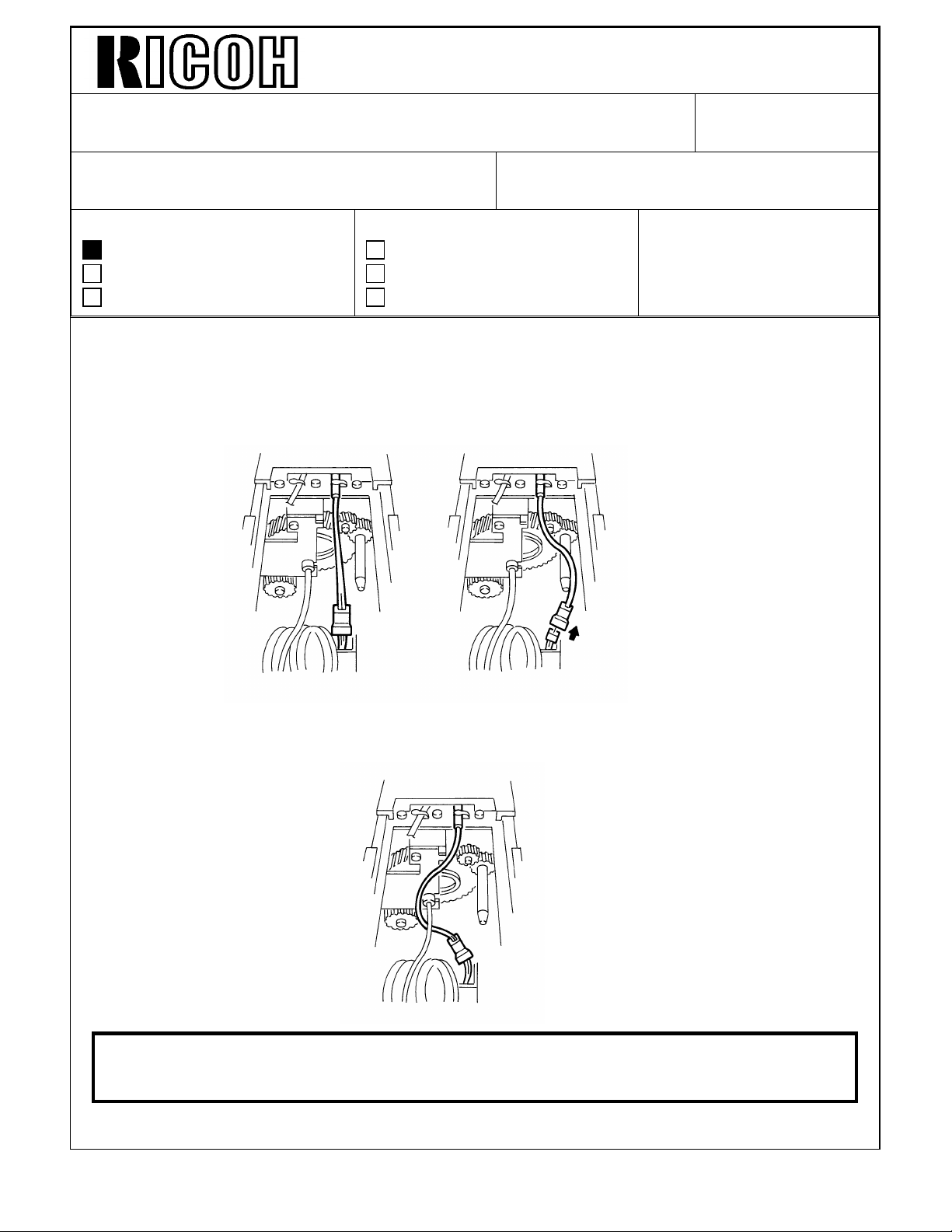
The oil end sensor harness is caught by the positioning pin and it is disconnected after the
fusing unit is pulled out and pushed in several times. If this occurs, oil end is not detected.
Revision of service manual
Information only
Other
FROM: 2nd Technical Support Section
MODEL: DFC-α
Normal condition When problem occur
To prevent this, the wiring route has been changed as shown below.
Caution: When reconnecting the hot roller’s fusing lamp after replacing hot roller
and/or pressure roller, be sure to route the oil end sensor harness as
shown above.
Page 2

Technical Bulletin No. RTB-001
SUBJECT: Oil end sensor harness wiring DATE: April 30, ’94
PAGE: 2 of 2
The oil end sensor harness wiring will be changed from the first May 1994 production
machine. (The cut-in serial number is as shown below.)
A109-17: A351405xxxx ~
A109-22: 67 940500 01 ~
A109-27: A351405xxxx ~
For the machines prior to the above serial number, we recommend changing the wiring at
the machine installation.
Page 3
Technical Bulletin No. RTB-002
SUBJECT: MANUAL CORRECTIONS DATE: MAY 15 ’94
PAGE: 1 of 2
PREPARED BY:S. MANO
CHECKED BY: S. Hamano
CLASSIFICATION:
Action Required
Troubleshooting
Retrofit Information
Please correct your service manual as follows:
Revision of service manual
Information only
Other
FROM: 2nd Technical Support Section
MODEL:
DFC - α
PAGE 4-21 Item "❷" Note
Incorrect :
standard data: (Standard data of the potential sensor calibration is blank)
Correct:
standard data: 230 ±20
PAGE 4-21 Item "❹"
Incorrect :
Indicates data (Vsg, Vsp, Vsg/Vsp) relate to ID sensor for each color and potential sensor
output while detecting the ID sensor pattern.
Correct:
Not used. (Actually this page 3 exists but all data indicated is " 0 ")
PAGE 4-24 Item "❶"
Incorrect :
Default setting must be selected.
Default:PID
Correct:
"PID" setting must be selected.
Default: Reset
Page 4
Technical Bulletin No. RTB-002
SUBJECT: MANUAL CORRECTIONS DATE: MAY 15 ’94
PAGE: 2 of 2
PAGE 4-26 Item "❼"
Incorrect :
Table of item ❼ is tinted
Correct:
Table of item ❼ is not tinted. This means the data can be changed in the field.
Select " Display " when editor is installed.
PAGE 4-42 Step #1, #3, #6
Incorrect :
1. Confirm that the main switch is ON.
2. Turn the DIP-switch 501 No.4 of the main control board ON and OFF.
3. Turn the main switch OFF and ON.
6. Replace all developer. (See section 5, Developer section.)
Correct:
1. Confirm that the main switch is OFF.
2. Turn the DIP-switch 501 No.4 of the main control board ON.
3. Turn the main switch ON. Then turn OFF the DIP-switch 501 No.4.
6. Replace all developer. (See section 5, Developer section.)
NOTE: SP4-2, No.403 (Process Control Mode Selection) - change the setting to "PID".
PAGE 5-69 DEVELOPER INSTALLATION Step #10
Incorrect :
Shake 2 packs of developer [G] 20 times then pour them in.
Correct:
Shake a pack of black developer [G] 20 times then pour them in.
Page 5

Technical Bulletin No. RTB-003
SUBJECT: SP402 ADJUSTMENT DATE: MAY 15 ’94
PAGE: 1 of 2
PREPARED BY: S.MANO
CHECKED BY: S. Hamano
CLASSIFICATION:
Action Required
Troubleshooting
Retrofit Information
Revision of service manual
Information only
Other
FROM: 2nd Technical Support Section
MODEL:
DFC - α
SYMPTOM
If paper becomes very dry under low humidity, the following symptoms are most visible.
1. Rough solid image surface and poor color reproduction in 4C mode.
2. Scattered toner around solid image areas in 1C mode.
The level of these symptoms depend on paper kinds such as smoothness and electrical
resistance, and how paper is dried.
POSSIBLE CAUSE
The transfer belt bias and transfer roller bias are adjusted for the machine under normal,
high, and low humidity conditions. The absolute humidity is detected by the humidity
sensor and the bias voltage changes accordingly. However, as the humidity sensor cannot
detect the moisture in the paper, those bias settings are for the paper just from the
package and not for too dried or too moistened paper.
Therefore, when we face the above symptoms, we can use the SP402 as a
troubleshooting but it might not solve them completely.
The best solution is to instruct the customer to keep the paper as fresh as possible and to
use a good pa per brand .
Page 6

Technical Bulletin No. RTB-003
SUBJECT: SP402 ADJUSTMENT DATE: MAY 15 ’94
PAGE: 2 of 2
COUNTERMEASURE
The following is how to use the SP as a troubleshooting.
1. ROUGH SOLID IMAGE SURFACE AND POOR COLOR REPRODUCTION IN
4C MODE
Increase the transfer roller bias for low humidity to improve this symptom.
Adjustment range: From 100% (1700V) to 150% (2550V)
If you have following side effect, decrease the setting to improve the side effect to an
acceptable level:
1) Incomplete toner transfer for low density areas (Too much transfer ability)
2) Feed roller mark in half toner image area in 1C mode
You should also check if the fresh paper can get reasonable copy image or not.
If not, decrease the setting.
2. SCATTERED TONER AROUND SOLID IMAGE AREAS IN 1C MODE
Increase the transfer belt bias for low humidity to improve this symptom.
Adjustment range: From 100% (2000V) to 140% (2800V)
If you have the following side effect, decrease the setting to improve the side effect to an
acceptable level:
1) The edge of letters become blurred with scattered toner (Toner scatters not all over
around the image but along the letter edges as thin lines.)
You should also check if the fresh paper can reasonable copy image or not. If not,
decrease the setting.
Page 7
Technical Bulletin No. RTB-004
SUBJECT:MAIN BOARD REPLACEMENT IN THE FIELD DATE: June 15 ’94
PAGE: 1 of 1
PREPARED BY: S. MANO
CHECKED BY: S. Hamano
CLASSIFICATION:
Action Required
Troubleshooting
Retrofit Information
Just after the mass-production started, the software (Main ROMs on the main control
board) was modified. (We do not mention the detail in this RTB)
We replaced the ROMs on all the mass-produced machines before shipping. In other
words, all of your machines have updated ROMs. (Up to now, the latest version main
ROMs are A1095265E and A1095267E).
However, the main control boards shipped out as initial stock parts were shipped without
the modification.
The main ROMs on the initial stock parts are A1095265B and A1095267B or A1095265D
and A109 5267D.
Therefore, when replacing the main control board in the field, please check the part
number suffix of the main ROMs on the main control board. If the suffix is B or D (C does
not exist), remove the main ROMs on the old main control board and install them on the
new main control board.
Revision of service manual
Information only
Other
FROM: 2nd Technical Support Section
MODEL: DFC - α
It is possible that the following symptoms occur if the ROMs are not updated when
replacing the main control board.
1. Toner scattering
2. Copy image leaning to some color (Bk,C,Y, mostly magenta).
3. Dirty background at the front or rear side of copies
4. Dirty background on entire copies
5. Toner spots on copies
6. Toner end misdetection
7. Toner end recovery error.
Page 8

Technical Bulletin No. RTB-005
SUBJECT: ORIGINAL DOUBLE FEEDING DATE:June 30, ’94
PAGE: 1 of 2
PREPARED BY: S. MANO
CHECKED BY: S. Hamano
CLASSIFICATION:
Action Required
Troubleshooting
Retrofit Information
This is additional information of RTB-025 "DJF double feeding".
Revision of service manual
Information only
Other
FROM: 2nd Technical Support Section
MODEL:DUAL JOB
FEEDER FOR DFC-α
<PHENOMENON>
Original double feeding (two or more sheets of the originals are fed at a time)
<POSSIBLE CAUSE>
The separation belts become dirty with the toner, loosing the friction to separate the
originals.
This is especially true when the customer feeds lots of poorly fused originals such as laser
output or cotton paper.
Separation Belts
Page 9

Technical Bulletin No. RTB-005
SUBJECT: ORIGINAL DOUBLE FEEDING DATE: June 30, ’94
PAGE: 2 of 2
<FIELD COUNTERMEASURE>
Replace the separation belts with the new parts. The new part number is A3769502.
The material of the separation belts has been changed to the one which less toner
adheres to.
NOTE: Depending on the type of originals that the customer use, there is still a possibility
that the separation belts become dirty. For those cases, cleaning the belts at every
visits, which was introduced in the previous RTB, is recommended.
This modification is implemented from the following serial numbers.
A376-10: 537403xxxx
A376-15: 41 240300 01
A376-17: A33840 30001
A376-22: 53 240300 01
A376-26: 3D80340001
A376-27: A33840 30150
Page 10
Technical Bulletin No. RTB-006
[A]
New style stopper
SUBJECT: Overtoning / Undertoning Countermeasures Reissued on: Nov. 30, ’94
DATE: OCT. 15 ,’94
PAGE: 1 of 2
PREPARED BY: S. Hizen
CHECKED BY: S. Hamano
CLASSIFICATION:
Action Required
Troubleshooting
Retrofit Information
SYMPTOM 2: Overtoning
Overtoning in the development unit just after installing a new toner bottle at toner end
CAUSE:
The toner fluidity increases when the toner bottle is shaken because the toner holds a lot
of air. This results in excessive toner being supplied into the development unit when a
new toner bottle is set by a customer.
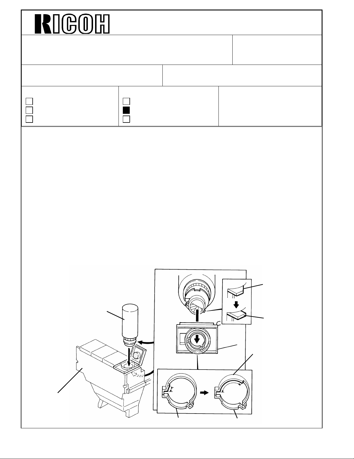
COUNTERMEASURE:
The open angle of the toner bottle shutter has been changed from 180 degrees to 70
degrees to make the toner supply time longer. This is to reduce the amount of air held by
toner at toner bottle installation. The following two modifications have been implemented
to change the shutter open angle.
Revision of service manual
Information only
Other
FROM: 2nd Technical Support Section
MODEL: DFC-alpha
Toner Bottle Guide Modification:
The toner bottle guide rib has been changed as shown in the illustration [A] from the first
production to stop the bottle rotation at 70 degrees.
Old style stopper
[B]
Toner
Bottle
Toner bottle guide rib
Toner Tank
Old toner guide New toner guide
Page 11
Technical Bulletin No. RTB-006
SUBJECT: Overtoning / Undertoning Countermeasure Reissued on: Nov. 30, ’94
DATE: OCT. 15, ’94
PAGE: 2 of 2
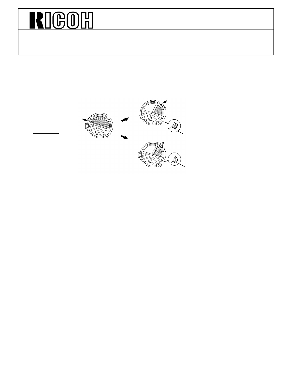
Toner Bottle Modification:
The shape of the stopper has been changed as shown in the illustration [B] (on the
previous page) from the following lots in each color toner. This is to prevent the stopper
from going inside the guide rib as shown below [C] when the toner bottle is turned strongly.
Open angle of toner bottle.
180°
Old Bottle Guide
with
Old Bottle
[C]
Start Lot # for the new style shape stopper bottle.
Black: Lot #4416001
Cyan: Lot #4416001
Magenta Lot #4416001
Yellow Lot #4416001
SYMPTOM 2: Undertoning when making many copies with a high image ratio.
70°
70°
New
style
stopper
Old
style
stopper
New Bottle Guide
with
New Bottle
New Bottle Guide
with
Old Bottle
The Toner End indicator is on even if there is toner still in the bottle.
CAUSE:
The toner supply amount from the toner hopper to the development unit is not enough
when making many copies with a high image ratio at the same time. This is due to the
development ability limitation.
COUNTERMEASURE:
Instruct a customer to make copies using lengthwise paper feed rather than sideways
paper feed. lengthwise feed takes longer than sideways feed. This allows enough toner
be supplied to the development unit to develop copies with a high image ratio.
Note: Continuous copy runs using lengthwise paper cause the undertone problem on
both sides of copy. (Please refer to RTB - 007 for details.)
Side-way paper feeding is recommended when more than 30 continuous copies
are made.
Page 12
Technical Bulletin No. RTB-007
SUBJECT: Light image along both sides of the copy DATE: OCT.15 ’94
PAGE: 1 of 2
PREPARED BY: S. MANO
CHECKED BY: S. Hamano
CLASSIFICATION:
Action Required
Troubleshooting
Retrofit Information
Revision of service manual
Information only
Other
FROM: 2nd Technical Support Section
MODEL:DFC-alpha
<SYMPTOM>
If the customer feeds small size paper (A4 or less/8 1/2 x 11 or less) mostly lengthwise, it
is possible that the image density of half tone areas image on both sides will become
lighter than the center area. (This symptom will be visible only when copying a half tone
original and using wide size copy paper.)
To prevent this, when feeding small size paper (A4 or less/8 1/2 x 11 or less), feed the
paper in sideways.
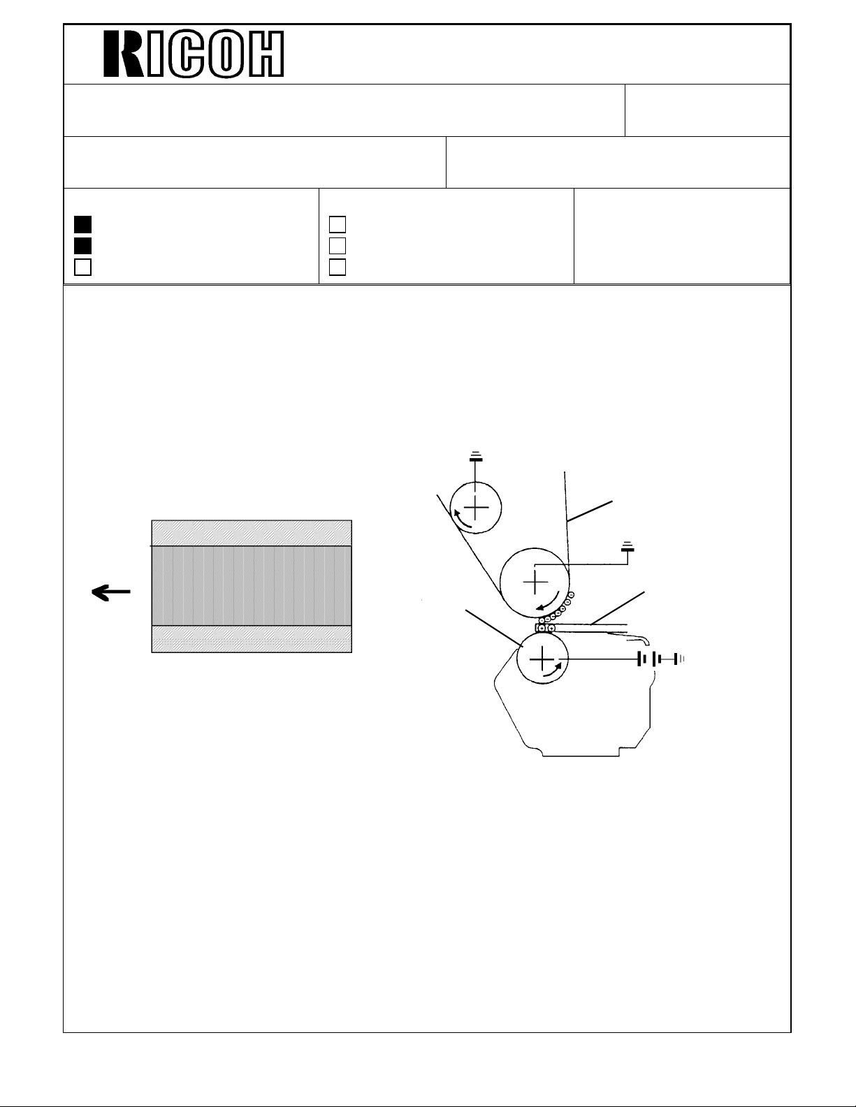
[B]
[A]
[C]
<REASON>
At the paper transfer area, the paper [A] affects the electrical resistance between the
transfer belt [B] and the transfer roller [C]. When the paper exists, less paper transfer bias
is applied from the transfer roller to the transfer belt.
If small size paper is continuously used, the front and rear areas of the transfer belt
continuously receive a stronger paper transfer bias than the center area of the transfer
belt. This is because the paper exists only at the center.
This gradually reduces the electrical resistance of the transfer belt ion the side. Especially
when many OHP transparency sheets are fed, the possibility to cause this symptom will be
higher due to higher paper transfer bias for OHP mode.
Page 13

Technical Bulletin No. RTB-007
SUBJECT: Light image along both sides of the copy DATE: OCT. 15 ’94
PAGE: 2 of 2
<COUNTERMEASURE>
If this symptom is weak, after feeding several (about 50 sheets) of wide paper, the transfer
belt’s electrical resistance will become even, and the symptom will disappear. (So, if the
customer feeds both narrow and wide paper alternately, the symptom does not appear.)
However, if this has no affect, you must replace the transfer belt. After replacing the
transfer belt, please instruct the customer to feed the paper in sideways as frequently as
possible.
Page 14

Technical Bulletin No. RTB-008
SUBJECT: Dirty background spots (377mm pitch) DATE: OCT. 15 ’94
PAGE: 1 of 2
PREPARED BY: S. MANO
CHECKED BY: S. Hamano
CLASSIFICATION:
Action Required
Troubleshooting
Retrofit Information
Revision of service manual
Information only
Other
FROM: 2nd Technical Support Section
MODEL: DFC-alpha
<SYMPTOM>
Slight dirty background areas appear. The distance between the background spots is
377mm. (diameter of the OPC drum is 120mm.)
377 mm
<POSSIBLE CAUSE>
Some of the adhesive from the tape [A] fixing the drum protective sheet is on the OPC
drum surface.
[A]
Page 15

Technical Bulletin No. RTB-008
SUBJECT: Dirty background spots (377mm pitch) DATE: OCT. 15’94
PAGE: 2 of 2
<INSTRUCTIONS>
Be sure not to contact the protective sheet tape with the OPC drum surface (Removing the
adhesive from the drum surface is difficult).
The surface of the OPC drum used in this model is easily dissolved by alcohol. So, for
normal maintenance, do not use alcohol.
However, you cannot remove the adhesive and all you can do is replace the OPC drum,
try to use alcohol with risk as a final solution. In this case, after wiping off the adhesive,
immediately remove the remaining alcohol on the OPC drum. Use the alcohol (isopropyl
alcohol is better than ethyl alcohol or methyl alcohol) after mixing it with water because
pure alcohol is too strong.
Page 16

REVISED ON JULY 31, ’95
Technical Bulletin No. RTB-009
SUBJECT: Add Toner Indication without Color Indication DATE: July 15, ’95
PAGE: 1 of 3
PREPARED BY: N. Kaiya
CHECKED BY:
CLASSIFICATION:
Action Required
Troubleshooting
Retrofit Information
Revision of service manual
Information only
Other
FROM: 2nd Technical Support Section
MODEL: DFC - α
Problem
Add toner Indication is lit without any color indication.
This problem happens when all of the following conditions occur.
1. Add toner condition is indicated for any of the color toners. The indication is normal at
this point.
2. Black and white copy is selected. The add toner indication turns off and the print key
turns green.
3. Editing, user program, color balance adjustment, user tool or any other mode which
changes the display from standard screen is selected.
4. The front door is opened and closed. At this point, the add toner condition is cleared.
5. When the display returns to the standard screen, the add toner indicator is lit without
any color indication.
Cause
Except for when the operation panel display is showing the standard display, the add toner
condition is not cleared within the operation panel display software, even when toner
replenishment is done. When the display returns to the standard screen, the add toner
indication remains on the display without color indication.
Page 17

REVISED ON JULY 31, ’95
Technical Bulletin No. RTB-009
SUBJECT: Add Toner Indication without Color Indication DATE: July 15, ’95
PAGE: 2 of 3
Countermeasure
Software modification is made. Two ROMs on the Main Board and two out of four ROMs
on the Operation Panel Board are modified.
Main Board ROM A109 5265F G
A109 5267F G
Operation Panel ROM: for -10, -17 machines
A109 5547C D
A109 5548D E
for -22 machine
A109 5647C D
A109 5648D E
Language ROM Kit English IC101 A544 51 02C D (not service parts)
IC102 A544 51 03C D (not service parts)
German IC101 A544 5112B C (not service parts)
IC102 A544 51 13B C (not service parts)
French IC101 A544 5122B C (not service parts)
IC102 A544 51 23B C (not service parts)
ItalianI IC101 A544 5132A B (not service parts)
IC102 A544 5133A B (not service parts)
Spanish IC101 A544 5142A B (not service parts)
IC102 A544 5143A B (not service parts)
Page 18

REVISED ON JULY 31, ’95
Technical Bulletin No. RTB-009
SUBJECT: Add Toner Indication without Color Indication DATE: July 15, ’95
PAGE: 3 of 3
CUT IN SERIAL NUMBER
A109-10 678502XX XX
A109-22 67950100 01
A109-27 A3515010 121
A109-17 A3515010 001
A109-26 3E501500 01
A109-29 A351502X XXX
Language ROM Kit : from Jan. ’95 production
Note: For the moment, only English, German, French, Italian and spanish will be
modified.
In case this problem is experienced in your field, please inform us. We will provide you
with the master ROMs.
Page 19

Technical Bulletin No. RTB-010
SUBJECT: Improvement of Copy Quality DATE:August 31, ’95
PAGE: 1 of 4
PREPARED BY: N. Kaiya
CHECKED BY: M. Iwasa
CLASSIFICATION:
Action Required
Troubleshooting
Retrofit Information
This RTB explains the modification made to the DFC alpha to improve its copy quality.
Revision of service manual
Information only
Other
FROM: 2nd Technical Support Section
MODEL:
DFC - α
Modified Parts
1. IPU Board
2. IPU ROM
3. Main Board ROM
4. Operation Panel Board ROM
5. An explanation sheet has been added to the Operating Instructions booklet.
(Page 4/4 of this RTB)
Please refer to MB No. 31 for part numbers, interchangeability, and the cut in serial
number.
Contents of the Modification
1. Improvement of the copy quality of photograph images
The copy quality of the photographic image varies depending on the type of original used.
With the new machine, the type of original to be copied can be specified from the following
three selections by User Tool 4. Sensitivity Adjustment, Photo Mode Setting
Printed Photo
Glossy Photo
Copied Photo
Based on the selection made, the copier will make adjustments to obtain the best copy
quality. This is achieved as follows.
The IPU converts the RGB video signal received from the Scanner Control Board into a
YMCBk video signal and outputs it to the LD unit. When doing this conversion, a color
correction is made to compensate for the difference between the ideal and actual
characteristics of each color toner. (Please refer to page 2-41 of the Service Manual for
details). With this modification, three different sets of color correction coefficient are
prepared to compensate for the differences in color reproduction resulting from differences
in characteristics of the photographic original used. The adjustment made for each type of
original is as follows.
Page 20

Technical Bulletin No. RTB-010
SUBJECT: Improvement of Copy Quality DATE:August 31, ’95
PAGE: 2 of 4
Printed Photo
When Printed Photo is selected, the copy quality is basically the same as in the old
machine.
Glossy Photo
Glossy photo should be selected when making copies from normal color photographs on
photographic paper. With this type of original;
- green may be copied brighter (or lighter)
- gray may become bluish.
To compensate for these,
- green is converted with less cyan
- the high ID part of cyan is made lighter.
Also, the amount of UCR is reduced to improve the reproduction of dark areas of the
original.
Copied Photo
Copied Photo should be selected when copying a copy. When doing this,
- a low ID area may not be reproduced well
- the copy may become reddish (strong magenta and less yellow).
To compensate for this:
- the low ID part of the original is reproduced darker
- yellow is reproduced darker and magenta is reproduced lighter.
General
For all three types of originals, The following improvements have been made.
The edge of black areas (for example, the girl’s hair on the C4 test chart) may be too
distinct (too black). To compensate for this, cyan, magenta, and yellow toner is added in
such areas.
Page 21

Technical Bulletin No. RTB-010
SUBJECT: Improvement of Copy Quality DATE:August 31,’95
PAGE: 3 of 4
2. Improvement of Auto Letter / Photo Separation
The letter/photo separation process is basically the same as before. A new algorithm is
used in the final evaluation process of the letter/photo separation to reduce separation
errors.
When installing Fiery Controller
When connecting a Fiery Controller to a modified machine, it is no longer necessary to
replace the ROMs on the main board and the IPU board. Please refer to the following
table for the necessary ROMs for each version of the IPU.
IPU Board P/ N A1095510 A109551 5 A1095519
IPU
Main
Board
Action
Replace the ROM
chips with the
following ROM chips.
IC303 V1.72 A109551 7 IC309 V1.72 A109551 8 IC509 A3996782 A3996782 IC522 A3996783 A3996783 -
Replace the ROM
chips with the
following ROM chips.
Do not replace the
ROMs.
Language ROM kit
Language ROM kit, necessary for some versions of the machines, are also modified but
the EDP code remains unchanged.
A round blue 9 mm sticker on the label indicates the new version of the ROM kit.
English ROM Type J
EDP CODE 208823
MODEL NO. A544-00
Blue sticker
Page 22

Technical Bulletin No. RTB-010
SUBJECT: Improvement of Copy Quality DATE:August 31, ’95
PAGE: 4 of 4
Supplemental Information (English) (A1098650)
Page 23

Technical Bulletin No. RTB-011
[B]
SUBJECT: Sorter Installation DATE: September 15, ’95
PAGE: 1 of 2
PREPARED BY: N. Kaiya
CHECKED BY: M. Iwasa
CLASSIFICATION:
Action Required
Troubleshooting
Retrofit Information
To comply with the CE mark, it is necessary to attach five ferrite cores when installing a
sorter on DFC - α. The ferrite cores have been enclosed in the screw bag of the DFC - α
from September production. Please refer to the following for the installation procedure of
the ferrite cores.
Additional procedure for sorter installation
Ferrite core P/N 16070418 4 pcs.
Ferrite core P/N 16070721 1 pc.
1. Turn off the main switch and unplug
the machine.
2. Remove the sorter top cover
(3 screws).
Revision of service manual
Information only
Other
FROM: 2nd Technical Support Section
MODEL:
DFC - α
[A]
3. Remove the sorter rear cover
(4 screws).
[D]
4. Attach the ferrite core ( [A] P/N
16070721 ) to the DC harness as
shown.
5. Remove the harnesses for second
bin solenoid (CN100) and third bin
solenoid (CN101). Pass the both
harnesses through the ferrite core
( [B] P/N 16070418 ) and reconnect
them to the sorter main board.
6. Remove the harnesses for the fourth bin solenoid (CN102) and the fifth bin solenoid
(CN103). Pass the both harnesses through the ferrite core ( [C] P/N 16070418 ) and
reconnect them to the sorter main board.
7. Remove the harnesses for the encoder (CN150) and the entry sensor LED (CN170).
Pass the both harnesses through the ferrite core ( [D] P/N 16070418 ) and reconnect
them to the sorter main board.
8. Remove the harnesses for the entry sensor Phototransistor (CN160) and the inlet
sensor (CN165). Pass the both harnesses through the ferrite core ( [E] P/N 16070418)
and reconnect them to the sorter main board.
[E]
[C]
9. Reassemble the unit.
Page 24

Technical Bulletin No. RTB-011
P/N 16070721
P/N 160706 38
P/N 16070623
SUBJECT: Sorter Installation DATE: September 15, ’95
PAGE: 2 of 2
Ferrite Cores Packed with DFC - α
For Sorter Installation
For DJF installation
P/N 160704 18
Page 25

Technical Bulletin No. RTB-012
SUBJECT: OPC Drum DATE:October 15, ’95
PAGE: 1 of 1
PREPARED BY: N. Kaiya
CHECKED BY:
CLASSIFICATION:
Action Required
Troubleshooting
Retrofit Information
The OPC drum for DFC - α has been changed from P/N A1099510 to P/N A1729510 as
informed by MB No.33.
Revision of service manual
Information only
Other
FROM: 2nd Technical Support Section
MODEL: DFC - α
Reason for the change
To extend the expected yield of the OPC drum, the OPC material has been improved. The
yield for the old drum was expected to be 40k scans based on our laboratory test results.
The OPC material was deteriorated by ozone or NOx gas generated mainly by corona
discharge, resulting in dirty background after around 50k scans. The new OPC material is
stronger against such gases. According to our laboratory tests, the level of background
remains unchanged until after 80k scans.
Expected Yield
The expected yield will be changed from 40k scans to 80k scans.
Interchangeability
The old and new OPC drums are completely interchangeable.
Page 26

Technical Bulletin No. RTB-013
SUBJECT: Anticondensation Heater DATE: November
15, ’95
PAGE: 1 of 1
PREPARED BY: N. Kaiya
CHECKED BY:
CLASSIFICATION:
Action Required
Troubleshooting
Retrofit Information
The following problem has been found on the production line. Please check this point
at machine installation.
Revision of service manual
Information only
Other
FROM: 2nd Technical Support Section
MODEL:
DFC - α
Problem
The second scanner contacts the anti-condensation heater lead wire. As a result, jitter
image may appear.
Anti-condensation Heater
Cause
A part of the anti-condensation heater lead wire has bent above the scanner unit base
plate.
Action
At installation, please check the routing of the anti-condensation heater lead wire. If it is
bent away from the scanner unit base plate, please flatten the lead wire so it is within 5
mm away from the base plate.
Note: This problem has been found with some earlier September production machines,
after new workers were assigned to assembling the scanner unit. The routing of
the lead wire has been strictly checked on the production line since the problem
was discovered, so we presume that this problem may happen only with a limited
number of September production machines.
Page 27

Technical Bulletin No. RTB-014
SUBJECT: Interface Kit Type A CE Mark Compliance DATE: December
31, ’95
PAGE: 1 of 9
PREPARED BY: N. Kaiya
CHECKED BY:
CLASSIFICATION:
Action Required
Troubleshooting
Retrofit Information
To comply with the CE mark standards, the following modifications have been made
to the Interface Kit Type A.
<Ferite Core>
Two ferrite cores are packed with the kit. Please refer to the attached installation
procedure of the interface kit for where to use these ferrite cores.
<Main Board ROMs>
The mainboard ROMs packed with the interface kit have been standardized with the
main board ROM on the copier main board.
Revision of service manual
Information only
Other
FROM: 2nd Technical Support Section
MODEL:
Interface Kit Type A
for DFC - α
A3996782 --> A1095104
A3996783 --> A1095106
At the same time, the ROMs have been updated from suffix L to suffix M.
A1095104L --> A1095104M
A1095106L --> A1095106M
The purpose of this update is to cut the signal from the scanner unit to the IPU when
using the copier in scanner mode. This will reduce the amount of electromagnetic
emission from the copier.
<CE Mark>
The CE mark is printed on the carton box. Please check this CE mark to distinguish
new kits from old kits, since there is no serial number for this kit.
Page 28

Technical Bulletin No. RTB-014
SUBJECT: Interface Kit Type A CE Mark Compliance DATE: December
31, ’95
PAGE: 2 of 9
Page 29

Technical Bulletin No. RTB-014
SUBJECT: Interface Kit Type A CE Mark Compliance DATE: December
31, ’95
PAGE: 3 of 9
Page 30

Technical Bulletin No. RTB-014
SUBJECT: Interface Kit Type A CE Mark Compliance DATE: December
31, ’95
PAGE: 4 of 9
Page 31

Technical Bulletin No. RTB-014
SUBJECT: Interface Kit Type A CE Mark Compliance DATE: December
31, ’95
PAGE: 5 of 9
Page 32

Technical Bulletin No. RTB-014
SUBJECT: Interface Kit Type A CE Mark Compliance DATE: December
31, ’95
PAGE: 6 of 9
Page 33

Technical Bulletin No. RTB-014
SUBJECT: Interface Kit Type A CE Mark Compliance DATE: December
31, ’95
PAGE: 7 of 9
Page 34

Technical Bulletin No. RTB-014
SUBJECT: Interface Kit Type A CE Mark Compliance DATE: December
31, ’95
PAGE: 8 of 9
Page 35

Technical Bulletin No. RTB-014
SUBJECT: Interface Kit Type A CE Mark Compliance DATE: December
31, ’95
PAGE: 9 of 9
Page 36

REVISED ON: MARCH 31, ’96
Technical Bulletin No. RTB-015
SUBJECT: New Type OPC Drum DATE: January 31, ’96
PAGE: 1 of 1
PREPARED BY: N. Kaiya
CHECKED BY:
CLASSIFICATION:
Action Required
Troubleshooting
Retrofit Information
The following is some additional information about the new type OPC drum used for DFC-α.
Please refer to RTB No.12 and MB No.33 for this change.
1.Cut-in Serial Numbers
The new type drum has been used in production from the following serial numbers.
A109-17 A3515110158
A109-22 6795110001
A109-26 3E1150001
A109-27 A3515110261
A109-57 S115115001
A109-67 from next production
2.Lot Number
You can distinguish the new type drum by the lot number printed on the flange of the drum.
If the second digit of the lot number is C, then the drum is a new type. If it is D, then the
drum is an old type.
Revision of service manual
Information only
Other
FROM: 2nd Technical Support Section
MODEL:
DFC - α
Example
1D52921234 - Old Type
1C50101234 - New Type
3.Remarks
When installing a new type drum, do not forget to apply setting powder and to rotate the
drum counterclockwise 3 times, as explained on page 5-57 of the Service Manual.
Page 37

Technical Bulletin No. RTB-016
SUBJECT: Standardization of Toner and Developer DATE: Sept. 30, ’96
PAGE: 1 of 2
PREPARED BY: N. Kaiya
CHECKED BY:
CLASSIFICATION:
Action Required
Troubleshooting
Retrofit Information
The toner and the developer for DFC-α have been standardized with those developed for
the new product, Lily.
The new toner and the new developer are compatible with the current toner and current
developer. A mixture of new and current toner, or mixtures of new toner and current
developer or current toner and new developer have no effect on the performance or copy
quality.
For the product names of the new toner and developer, please refer to the tables below.
Ricoh
toner black RICOH COLOR TONER TYPE F BLACK
yellow RICOH COLOR TONER TYPE F YELLOW
magenta RICOH COLOR TONER TYPE F MAGENTA
cyan RICOH COLOR TONER TYPE F CYAN
developer black RICOH COLOR DEVELOPER TYPE F BLACK
yellow RICOH COLOR DEVELOPER TYPE F YELLOW
magenta RICOH COLOR DEVELOPER TYPE F MAGENTA
cyan RICOH COLOR DEVELOPER TYPE F CYAN
Revision of service manual
Information only
Other
FROM: 1st Field Information Dept. QAC
MODEL:
DFC - α
Savin
toner black SAVIN COLOR TONER BLACK FOR SAVIN SDC206
yellow SAVIN COLOR TONER YELLOW FOR SAVIN SDC206
magenta SAVIN COLOR TONER MAGENTA FOR SAVIN SDC206
cyan SAVIN COLOR TONER CYAN FOR SAVIN SDC206
developer black SAVIN COLOR DEVELOPER BLACK FOR SAVIN SDC103/206
yellow SAVIN COLOR DEVELOPER YELLOW FOR SAVIN SDC103/206
magenta SAVIN COLOR DEVELOPER MAGENTA FOR SAVIN
SDC103/206
cyan SAVIN COLOR DEVELOPER CYAN FOR SAVIN SDC103/206
Page 38

Technical Bulletin No. RTB-016
SUBJECT: Standardization of Toner and Developer DATE: Sept. 30, ’96
PAGE: 2 of 2
Infotec
toner black TONER BLACK TYPE XX/1
yellow TONER YELLOW TYPE XX/1
magenta TONER MAGENTA TYPE XX/1
cyan TONER CYAN TYPE XX/1
developer black DEVELOPER BLACK TYPE XX
yellow DEVELOPER YELLOW TYPE XX
magenta DEVELOPER MAGENTA TYPE XX
cyan DEVELOPER CYAN TYPE XX
NRG
toner black CT107BLK
yellow CT107YLW
magenta CT107MGT
cyan CT107CYN
developer black CD107BLK
yellow CD107YLW
magenta CD107MGT
cyan CD107CYN
Page 39

Technical Bulletin No. RTB-017
SUBJECT: Grease for Transfer Belt Unit and Transfer Roller Unit DATE:Oct. 31, ’96
PAGE: 1 of 1
PREPARED BY: N. Kaiya
CHECKED BY:
CLASSIFICATION:
Action Required
Troubleshooting
Retrofit Information
Please use the KS660 grease (P/N G0049668) for lubricating the end of the bias roller
shaft and the end of the transfer roller shaft. The KS660 grease is more conductive than
the 40M grease currently recommended.
Revision of service manual
Information only
Other
Transfer
Roller Shaft
FROM: 1st Field Information Dept. QAC
MODEL: DFC - α
Belt Bias Roller
Shaft
P/N G004 9668
Grease KS660
Page 40

RICOH Technical Bulletin
Model: DFC-α
Subject: Transfer Belt Tension Release Wedge Prepared by: N. Kaiya
From: QAC 1st Field Information Dept. Checked by: T. Inoue
Classification:
In order to release the tension of the transfer belt during transportation, the Transfer Belt
Release Wedges are installed on the front and rear belt tension roller bearing holders.
Please do not forget to remove the wedges at machine installation.
To remove the wedge, push the wedge toward the bearing holder and slide it inside
slightly.
Troubleshooting
Mechanical
Paper path
Other ( )
Date: 31-Mar-97
Part information
Electrical
Transmit/receive
No: 18
Action required
Service manual revision
Retrofit information
1/2
Page 41

RICOH Technical Bulletin
Model: DFC-α
MODEL NAME V/ Hz DESTINATION CODE SERIAL NUMBER
Savin SC106 115V / 60Hz USA, CANADA A109- 15 50701xxxx
Ricoh NC5006 115V / 60Hz USA, CANADA A109- 17 A3517010001
Ges 2706 / NSA
C406 / REX
CC8406
Infotec 7306 230V / 50Hz EUROPE etc. A109- 26 3E5701xxxx
Ricoh NC 5006 230V / 50Hz EUROPE etc. A109- 27 A351701xxxx
Sharp AR- C860 115V / 60Hz USA, CANADA A109- 57 S11701xxxx
Sharp AR- C860 230V/ 50Hz EUROPE A109- 67 S11701xxxx
230V / 50Hz EUROPE etc. A109- 22 6797020001
Date: 31-Mar-97 No: 18 2/2
 Loading...