

Page 1
RICOH GROUP COMPANIES
B022/B027
SERVICE MANUAL
001197MIU
Page 2

Page 3

®
®
SERVICE MANUAL
B022/B027
RICOH GROUP COMPANIES
Page 4

Page 5

B022/B027
SERVICE MANUAL
001197MIU
Page 6

Page 7

It is the reader's responsibility when discussing the information contained
within this document to maintain a level of confidentiality that is in the best
interest of Ricoh Corporation and its member companies.
NO PART OF THIS DOCUMENT MAY BE REPRODUCED IN ANY
FASHION AND DISTRIBUTED WITHOUT THE PRIOR
PERMISSION OF RICOH CORPORATION.
All product names, domain names or product illustrations, including
desktop images, used in this document are trademarks, registered
trademarks or the property of their respective companies.
They are used throughout this book in an informational or editorial fashion
only and for the benefit of such companies. No such use, or the use of
any trade name, or web site is intended to convey endorsement or other
affiliation with Ricoh products.
2001 RICOH Corporation. All rights reserved.
Page 8

Page 9

n
t
s
r
h
g
o
l
y
WARNING
The Service Manual contains informatio
regarding service techniques, procedures,
processes and spare parts of office equipmen
distributed by Ricoh Corporation. Users of thi
manual should be either service trained o
certified by successfully completing a Rico
Technical Training Program.
Untrained and uncertified users utilizin
information contained in this service manual t
repair or modify Ricoh equipment risk persona
injury, damage to property or loss of warrant
protection.
Ricoh Corporation
Page 10

Page 11

LEGEND
PRODUCT CODE
B022 2212 5622AG Aficio 1022 2522
B027 2712 5627AG Aficio 1027 2527
DOCUMENTATION HISTORY
REV. NO. DATE COMMENTS
*
COMPANY
GESTETNER LANIER RICOH SAVIN
11/2001 Original Printing
Page 12

Page 13

B022/B027
TABLE OF CONTENTS
INSTALLATION
1 OVERALL MACHINE INFORMATION.........................................1-1
1.1 SPECIFICATIONS.................................................................................... 1-1
1.2 MACHINE CONFIGURATION.................................................................. 1-5
1.2.1 SYSTEM COMPONENTS ............................................................... 1-5
1.2.2 INSTALLABLE OPTION TABLE...................................................... 1-7
Copier options...................................................................................... 1-7
Fax option............................................................................................ 1-7
Printer/scanner options........................................................................ 1-7
1.3 PAPER PATH........................................................................................... 1-8
1.4 MECHANICAL COMPONENT LAYOUT................................................... 1-9
1.5 ELECTRICAL COMPONENT DESCRIPTIONS...................................... 1-11
1.6 DRIVE LAYOUT ..................................................................................... 1-14
1.7 COPY PROCESS...................................................................................1-15
1.7.1 OVERVIEW ................................................................................... 1-15
1.8 BOARD STRUCTURE............................................................................ 1-17
1.8.1 OVERVIEW ................................................................................... 1-17
1.8.2 CONTROLLER.............................................................................. 1-19
DETAILED SECTION DESCRIPTIONS
2 DETAILED SECTION DESCRIPTIONS........................................2-1
2.1 SCANNING............................................................................................... 2-1
2.1.1 OVERVIEW ..................................................................................... 2-1
2.1.2 SCANNER DRIVE ........................................................................... 2-2
2.1.3 ORIGINAL SIZE DETECTION IN PLATEN MODE.......................... 2-3
2.2 IMAGE PROCESSING ............................................................................. 2-5
2.2.1 OVERVIEW ..................................................................................... 2-5
2.2.2 SBU (SENSOR BOARD UNIT)........................................................ 2-6
2.2.3 AUTO IMAGE DENSITY.................................................................. 2-7
2.2.4 IPU (IMAGE PROCESSING UNIT).................................................. 2-8
Overview.............................................................................................. 2-8
Image Processing Modes..................................................................... 2-9
Image Processing Path...................................................................... 2-10
Overview............................................................................................ 2-10
SP Modes for Each Image Processing Step ...................................... 2-11
Text Mode.......................................................................................... 2-11
Photo Mode........................................................................................ 2-12
Text/Photo Mode................................................................................ 2-13
Pale Mode.......................................................................................... 2-14
Generation Copy................................................................................ 2-15
Auto Shading...................................................................................... 2-16
SM i B022/B027
Page 14

Pre-Filtering........................................................................................ 2-16
Main Scan Magnification/Reduction................................................... 2-16
Mirroring for ADF Mode...................................................................... 2-16
Characteristic Detection..................................................................... 2-17
Filtering .............................................................................................. 2-17
Overview............................................................................................ 2-17
MTF Filter........................................................................................... 2-17
Smoothing Filter................................................................................. 2-17
Characteristic Filter............................................................................ 2-17
Independent Dot Erase...................................................................... 2-18
Background Erase.............................................................................. 2-18
ID Gamma (γ) Correction ................................................................... 2-18
Gradation Processing......................................................................... 2-18
Overview............................................................................................ 2-18
Grayscale Processing........................................................................ 2-19
Binary Picture Processing.................................................................. 2-19
Error Diffusion.................................................................................... 2-19
Dithering............................................................................................. 2-19
Line width correction.......................................................................... 2-19
2.2.5 VIDEO CONTROL UNIT (VCU)..................................................... 2-20
Fine Character and Image (FCI)........................................................ 2-20
2.3 LASER EXPOSURE............................................................................... 2-21
2.3.1 OVERVIEW ................................................................................... 2-21
2.3.2 AUTO POWER CONTROL (APC) ................................................. 2-22
2.3.3 LD SAFETY SWITCH.................................................................... 2-23
2.4 PHOTOCONDUCTOR UNIT (PCU)........................................................ 2-24
2.4.1 OVERVIEW ................................................................................... 2-24
2.4.2 DRIVE............................................................................................ 2-25
2.4.3 NEW PCU DETECTION................................................................ 2-26
2.5 DRUM CHARGE..................................................................................... 2-27
2.5.1 OVERVIEW ................................................................................... 2-27
2.5.1 CHARGE ROLLER VOLTAGE CORRECTION............................. 2-28
Correction for Environmental Conditions............................................ 2-28
2.5.2 ID SENSOR PATTERN PRODUCTION TIMING........................... 2-29
2.5.3 DRUM CHARGE ROLLER CLEANING......................................... 2-30
2.6 DEVELOPMENT..................................................................................... 2-31
2.6.1 OVERVIEW ................................................................................... 2-31
2.6.2 DRIVE............................................................................................ 2-32
2.6.3 DEVELOPER MIXING................................................................... 2-33
2.6.4 DEVELOPMENT BIAS................................................................... 2-34
2.6.5 TONER SUPPLY........................................................................... 2-35
Toner bottle replenishment mechanism............................................. 2-35
Toner supply mechanism................................................................... 2-36
2.6.6 TONER DENSITY CONTROL....................................................... 2-37
Overview............................................................................................ 2-37
Toner density sensor initial setting..................................................... 2-39
Toner density measurement .............................................................. 2-39
Vsp/Vsg detection.............................................................................. 2-39
Toner supply reference voltage (Vref) determination......................... 2-39
B022/B027 ii SM
Page 15

Toner supply determination................................................................ 2-39
Toner Supply Motor On Time Determinations.................................... 2-40
2.6.7 TONER SUPPLY IN ABNORMAL SENSOR CONDITIONS.......... 2-41
ID sensor............................................................................................ 2-41
TD Sensor.......................................................................................... 2-41
2.6.8 TONER NEAR END/END DETECTION AND RECOVERY........... 2-41
Toner Near End Detection ................................................................. 2-41
Toner Near End Recovery.................................................................. 2-42
Toner End Detection.......................................................................... 2-42
Toner End Recovery.......................................................................... 2-42
2.7 DRUM CLEANING AND TONER RECYCLING...................................... 2-43
2.7.1 DRUM CLEANING......................................................................... 2-43
2.7.2 TONER RECYCLING .................................................................... 2-44
2.8 PAPER FEED......................................................................................... 2-45
2.8.1 OVERVIEW ................................................................................... 2-45
2.8.2 PAPER FEED DRIVE MECHANISM ............................................. 2-46
2.8.3 PAPER FEED AND SEPARATION MECHANISM......................... 2-47
2.8.4 PAPER LIFT MECHANISM............................................................ 2-48
2.8.5 PAPER END DETECTION............................................................. 2-49
2.8.6 PAPER HEIGHT DETECTION....................................................... 2-50
2.8.7 FEED PRESSURE ADJUSTMENT FOR PAPER SIZE................. 2-51
Overview............................................................................................ 2-51
Paper Size Thresholds....................................................................... 2-51
Feed Pressure Adjustment................................................................. 2-52
Effect of the Amount of Remaining Paper.......................................... 2-52
From tray full to paper near-end......................................................... 2-52
From paper near end to paper end.................................................... 2-53
2.8.8 PAPER SIZE DETECTION............................................................ 2-54
2.8.9 SPECIAL PAPER SETTING.......................................................... 2-55
2.8.10 SIDE AND END FENCES............................................................ 2-56
Side Fences....................................................................................... 2-56
End Fence.......................................................................................... 2-56
2.8.11 PAPER REGISTRATION............................................................. 2-57
2.9 IMAGE TRANSFER AND PAPER SEPARATION.................................. 2-58
2.9.1 OVERVIEW ................................................................................... 2-58
2.9.2 IMAGE TRANSFER CURRENT TIMING....................................... 2-59
2.9.3 TRANSFER ROLLER CLEANING................................................. 2-60
2.9.4 PAPER SEPARATION MECHANISM............................................ 2-60
2.10 IMAGE FUSING AND PAPER EXIT..................................................... 2-61
2.10.1 OVERVIEW ................................................................................. 2-61
2.10.2 FUSING DRIVE AND RELEASE MECHANISM........................... 2-62
2.10.3 FUSING ENTRANCE GUIDE SHIFT MECHANISM.................... 2-63
2.10.4 PRESSURE ROLLER.................................................................. 2-64
2.10.5 CLEANING MECHANISM............................................................ 2-64
2.10.6 FUSING TEMPERATURE CONTROL......................................... 2-65
Temperature Control.......................................................................... 2-65
Fusing Lamp Control.......................................................................... 2-66
2.10.7 OVERHEAT PROTECTION......................................................... 2-67
2.10.8 PAPER EXIT................................................................................ 2-67
SM iii B022/B027
Page 16

2.11 ENERGY SAVER MODES ................................................................... 2-68
2.11.1 OVERVIEW ................................................................................. 2-68
2.11.2 ENERGY SAVER MODE............................................................. 2-69
Entering the energy saver mode........................................................ 2-69
What happens in energy saver mode................................................. 2-69
Return to stand-by mode.................................................................... 2-69
2.11.3 AUTO OFF MODE....................................................................... 2-70
Entering off stand-by and off modes .................................................. 2-70
Off Stand-by mode............................................................................. 2-70
Off Mode............................................................................................ 2-70
Returning to stand-by mode............................................................... 2-70
INSTALLATION PROCEDURE
3 INSTALLATION PROCEDURE.................................................... 3-1
3.1 INSTALLATION REQUIREMENTS .......................................................... 3-1
3.1.1 ENVIRONMENT .............................................................................. 3-1
3.1.2 MACHINE LEVEL............................................................................ 3-1
3.1.3 MINIMUM SPACE REQUIREMENTS.............................................. 3-2
3.1.4 POWER REQUIREMENTS.............................................................. 3-3
3.2 COPIER INSTALLATION.......................................................................... 3-4
3.2.1 POWER SOCKETS FOR PERIPHERALS....................................... 3-4
3.2.2 INSTALLATION FLOW CHART....................................................... 3-5
3.2.3 ACCESSORY CHECK..................................................................... 3-6
3.2.4 INSTALLATION PROCEDURE........................................................ 3-7
3.3 PAPER TRAY UNIT INSTALLATION..................................................... 3-11
3.3.1 ACCESSORY CHECK................................................................... 3-11
3.3.2 INSTALLATION PROCEDURE...................................................... 3-11
3.4 LCT INSTALLATION .............................................................................. 3-14
3.4.1 ACCESSORY CHECK................................................................... 3-14
3.4.2 INSTALLATION PROCEDURE...................................................... 3-14
3.5 AUTO REVERSE DOCUMENT FEEDER INSTALLATION.................... 3-17
3.5.1 ACCESSORY CHECK................................................................... 3-17
3.5.2 INSTALLATION PROCEDURE...................................................... 3-17
3.6 INTERCHANGE UNIT INSTALLATION.................................................. 3-20
3.6.1 COMPONENT CHECK.................................................................. 3-20
3.6.2 INSTALLATION PROCEDURE...................................................... 3-21
3.7 1-BIN TRAY UNIT INSTALLATION ........................................................ 3-23
3.7.1 COMPONENT CHECK.................................................................. 3-23
3.7.2 INSTALLATION PROCEDURE...................................................... 3-23
3.8 SHIFT TRAY........................................................................................... 3-26
3.8.1 COMPONENT CHECK.................................................................. 3-26
3.8.2 INSTALLATION PROCEDURE...................................................... 3-26
3.9 BY-PASS FEED UNIT INSTALLATION.................................................. 3-28
3.9.1 COMPONENTS CHECK................................................................ 3-28
3.9.2 INSTALLATION PROCEDURE...................................................... 3-28
3.10 DUPLEX UNIT INSTALLATION............................................................ 3-30
3.10.1 ACCESSORY CHECK................................................................. 3-30
B022/B027 iv SM
Page 17

3.10.2 INSTALLATION PROCEDURE.................................................... 3-31
3.11 BRIDGE UNIT INSTALLATION............................................................ 3-33
3.11.1 ACCESSORY CHECK................................................................. 3-33
3.11.2 INSTALLATION PROCEDURE.................................................... 3-33
3.12 1,000-SHEET FINISHER INSTALLATION............................................ 3-35
3.12.1 ACCESSORY CHECK................................................................. 3-35
3.12.2 INSTALLATION PROCEDURE.................................................... 3-36
3.13 500-SHEET FINISHER INSTALLATION............................................... 3-39
3.13.1 ACCESSORY CHECK................................................................. 3-39
3.13.2 INSTALLATION PROCEDURE.................................................... 3-40
3.14 PLATEN COVER INSTALLATION........................................................ 3-42
3.14.1 MEMORY (G578/G579)............................................................... 3-43
3.14.2 HDD (B420)................................................................................. 3-44
3.15 KEY COUNTER INSTALLATION ......................................................... 3-46
3.16 ANTI-CONDENSATION HEATER........................................................ 3-48
3.17 TRAY HEATER..................................................................................... 3-49
3.18 TRAY HEATER (OPTIONAL PAPER TRAY UNIT).............................. 3-51
3.19 TRAY HEATER (OPTIONAL LCT) ....................................................... 3-54
SERVICE TABLES
4 SERVICE TABLES.......................................................................4-1
4.1 GENERAL CAUTION................................................................................ 4-1
4.1.1 PCU (PHOTOCONDUCTOR UNIT)................................................. 4-1
4.1.2 TRANSFER ROLLER UNIT............................................................. 4-1
4.1.3 SCANNER UNIT.............................................................................. 4-1
4.1.4 LASER UNIT.................................................................................... 4-2
4.1.5 FUSING UNIT.................................................................................. 4-2
4.1.6 PAPER FEED.................................................................................. 4-2
4.1.7 OTHERS.......................................................................................... 4-2
4.2 SERVICE PROGRAM MODE................................................................... 4-3
4.2.1 SERVICE PROGRAM MODE OPERATION.................................... 4-3
Entering and Exiting SP mode............................................................. 4-3
SP Mode Button Summary................................................................... 4-4
Switching Between SP Mode and Copy Mode for Test Printing........... 4-5
Selecting the Program Number............................................................ 4-5
4.2.2 SERVICE PROGRAM MODE TABLES........................................... 4-6
SP1-XXX: Feed.................................................................................... 4-6
SP2-XXX: Drum................................................................................. 4-16
SP4-XXX: Scanner............................................................................. 4-25
SP5-XXX: Mode................................................................................. 4-31
SP6-XXX: Peripherals........................................................................ 4-41
SP7-XXX: Data Log ........................................................................... 4-43
SP9-XXX: Debug/Testing................................................................... 4-52
4.2.3 TEST PATTERN PRINTING (SP2-902-3) ..................................... 4-53
4.2.4 INPUT CHECK............................................................................... 4-54
Main Machine Input Check (SP5-803)............................................... 4-54
ARDF Input Check (SP6-007)............................................................ 4-57
SM v B022/B027
Page 18

Finisher Input Check (SP6-117)......................................................... 4-58
4.2.5 OUTPUT CHECK........................................................................... 4-60
Main Machine Output Check (SP5-804)............................................. 4-60
ARDF Output Check (SP6-008)......................................................... 4-62
Finisher Output Check (SP6-118)...................................................... 4-62
4.2.6 SMC DATA LISTS (SP5-990)........................................................ 4-63
4.2.7 MEMORY ALL CLEAR (SP5-801)................................................. 4-64
Using a Flash Memory Card............................................................... 4-64
Without Using a Flash Memory Card................................................. 4-65
4.2.8 UPLOADING/DOWNLOADING NVRAM DATA............................. 4-66
Uploading NVRAM Data (SP5-824)................................................... 4-66
Downloading NVRAM Data (SP5-825)............................................... 4-67
4.2.9 APS OUTPUT DISPLAY (SP4-301)............................................... 4-68
4.2.10 DF APS SENSOR OUTPUT DISPLAY (SP6-901)....................... 4-69
4.2.11 NIP BAND WIDTH MEASUREMENT (SP1-109)......................... 4-70
4.3 PROGRAM DOWNLOAD....................................................................... 4-71
4.4 SOFTWARE RESET .............................................................................. 4-72
4.5 SYSTEM SETTINGS AND COPY SETTING RESET............................. 4-72
4.5.1 SYSTEM SETTING RESET........................................................... 4-72
4.5.2 COPIER SETTING RESET............................................................ 4-73
4.6 USER TOOLS......................................................................................... 4-74
4.6.1 HOW TO USE UP MODE.............................................................. 4-74
UP Mode Initial Screen: User Tools/Counter Display ......................... 4-74
System Settings................................................................................. 4-74
Copier/Document Server Features..................................................... 4-75
Printer, Facsimile, Scanner Settings.................................................. 4-75
Inquiry................................................................................................ 4-75
Counter.............................................................................................. 4-76
4.7 LEDS...................................................................................................... 4-77
Controller ........................................................................................... 4-77
SBCU................................................................................................. 4-77
IPU..................................................................................................... 4-77
4.8 DIP SWITCHES...................................................................................... 4-77
Controller: DIP SW2........................................................................... 4-77
SBCU: DIP SW102 ............................................................................ 4-77
4.9 SPECIAL TOOLS AND LUBRICANTS ................................................... 4-78
4.9.1 SPECIAL TOOLS........................................................................... 4-78
4.9.2 LUBRICANTS................................................................................ 4-78
PREVENTIVE MAINTENANCE SCHEDULE
5 PREVENTIVE MAINTENANCE SCHEDULE................................5-1
5.1 PM TABLE................................................................................................ 5-1
REPLACEMENT AND ADJUSTMENT
6 REPLACEMENT AND ADJUSTMENT.........................................6-1
B022/B027 vi SM
Page 19

6.1 SCANNER UNIT....................................................................................... 6-1
6.1.1 EXPOSURE GLASS........................................................................ 6-1
6.1.2 SCANNER EXTERIOR/OPERATION PANEL................................. 6-2
6.1.3 LENS BLOCK ASSEMBLY.............................................................. 6-3
6.1.4 ORIGINAL SIZE SENSORS............................................................ 6-4
6.1.5 EXPOSURE LAMP.......................................................................... 6-5
6.1.6 SCANNER MOTOR/LAMP STABILIZER......................................... 6-6
6.1.7 SCANNER WIRES........................................................................... 6-7
6.2 LASER UNIT........................................................................................... 6-10
6.2.1 CAUTION DECAL LOCATIONS.................................................... 6-10
6.2.2 LASER UNIT.................................................................................. 6-11
6.2.3 POLYGON MIRROR MOTOR....................................................... 6-12
6.2.4 LD UNIT......................................................................................... 6-12
6.2.5 LASER SYNCHRONIZATION DETECTOR................................... 6-13
6.3 PHOTOCONDUCTOR UNIT (PCU)........................................................ 6-14
6.3.1 PCU............................................................................................... 6-14
6.4 TRANSFER UNIT................................................................................... 6-15
6.4.1 TRANSFER ROLLER UNIT........................................................... 6-15
6.4.2 IMAGE DENSITY SENSOR........................................................... 6-16
6.5 FUSING/EXIT......................................................................................... 6-17
6.5.1 FUSING UNIT................................................................................ 6-17
6.5.2 THERMISTORS............................................................................. 6-17
6.5.3 THERMOFUSE.............................................................................. 6-18
6.5.4 HOT ROLLER AND FUSING LAMP.............................................. 6-20
6.5.5 PRESSURE ROLLER/CLEANING ROLLER................................. 6-21
6.5.6 PAPER EXIT SENSOR/PAPER OVERFLOW SENSOR............... 6-22
6.6 PAPER FEED......................................................................................... 6-23
6.6.1 FEED ROLLERS............................................................................ 6-23
6.6.2 PAPER END SENSOR.................................................................. 6-24
6.6.3 PAPER TRAY LIFT MOTORS....................................................... 6-25
6.6.4 REGISTRATION CLUTCH............................................................. 6-26
6.6.5 PAPER FEED CLUTCHES............................................................ 6-27
Lower Paper Feed Clutch .................................................................. 6-27
Upper Paper Feed Clutch. ................................................................. 6-27
6.6.6 RELAY CLUTCHES....................................................................... 6-28
6.6.7 PAPER SIZE DETECTOR............................................................. 6-29
6.6.8 REGISTRATION SENSOR............................................................ 6-30
6.6.9 RELAY SENSORS......................................................................... 6-31
Upper Relay Sensor........................................................................... 6-31
Lower Relay Sensor........................................................................... 6-31
6.7 PCBS AND OTHER ITEMS.................................................................... 6-32
6.7.1 CONTROLLER BOARD................................................................. 6-32
6.7.2 SBCU BOARD............................................................................... 6-33
6.7.3 POWER PACK............................................................................... 6-33
6.7.4 MAIN MOTOR................................................................................ 6-34
6.7.5 PSU ............................................................................................... 6-35
6.8 COPY ADJUSTMENTS: PRINTING/SCANNING................................... 6-36
6.8.1 PRINTING...................................................................................... 6-36
Registration - Leading Edge/Side-to-Side.......................................... 6-36
SM vii B022/B027
Page 20

Blank Margin...................................................................................... 6-37
Main Scan Magnification.................................................................... 6-37
Parallelogram Image Adjustment....................................................... 6-38
6.8.2 SCANNING.................................................................................... 6-39
Registration: Platen Mode.................................................................. 6-39
Magnification...................................................................................... 6-39
Standard White Density Adjustment................................................... 6-40
6.8.3 ADF IMAGE ADJUSTMENT.......................................................... 6-41
Registration........................................................................................ 6-41
Sub Scan Magnification ..................................................................... 6-41
6.8.4 TOUCH SCREEN CALIBRATION ................................................. 6-42
TROUBLESHOOTING
7 TROUBLESHOOTING..................................................................7-1
7.1 SERVICE CALL CONDITIONS................................................................. 7-1
7.1.1 SUMMARY....................................................................................... 7-1
7.1.2 SC CODE DESCRIPTIONS............................................................. 7-2
7.2 SELF-DIAGNOSTIC MODE.................................................................... 7-12
7.2.1 SELF-DIAGNOSTIC MODE AT POWER ON................................ 7-12
7.2.2 DETAILED SELF-DIAGNOSTIC MODE........................................ 7-13
Executing Detailed Self-Diagnosis..................................................... 7-13
7.3 PAPER FEED TROUBLESHOOTING.................................................... 7-15
7.4 SKEWED IMAGE.................................................................................... 7-16
7.5 ELECTRICAL COMPONENT DEFECTS................................................ 7-17
7.5.1 SENSORS..................................................................................... 7-17
7.5.2 SWITCHES.................................................................................... 7-19
7.6 BLOWN FUSE CONDITIONS................................................................. 7-20
PAPER TRAY UNIT (A860/B390)
1 OVERALL MACHINE INFORMATION.........................................8-1
1.1 SPECIFICATIONS.................................................................................... 8-1
1.2 MECHANICAL COMPONENT LAYOUT................................................... 8-2
1.3 ELECTRICAL COMPONENT LAYOUT.................................................... 8-3
1.4 ELECTRICAL COMPONENT DESCRIPTION.......................................... 8-4
1.5 DRIVE LAYOUT ....................................................................................... 8-5
2 DETAILED DESCRIPTIONS........................................................8-6
2.1 PAPER FEED AND SEPARATION MECHANISM.................................... 8-6
2.2 PAPER LIFT MECHANISM...................................................................... 8-7
2.3 PAPER END DETECTION....................................................................... 8-9
2.4 PAPER HEIGHT DETECTION ............................................................... 8-10
2.5 PAPER SIZE DETECTION..................................................................... 8-12
2.6 SIDE AND END FENCES....................................................................... 8-13
Side Fences....................................................................................... 8-13
End Fence.......................................................................................... 8-13
B022/B027 viii SM
Page 21

3 REPLACEMENT AND ADJUSTMENT....................................... 8-14
3.1 FEED ROLLER REPLACEMENT........................................................... 8-14
3.2 TRAY MAIN BOARD REPLACEMENT................................................... 8-15
3.3 TRAY MOTOR REPLACEMENT............................................................ 8-15
3.4 RELAY CLUTCH REPLACEMENT......................................................... 8-16
3.5 UPPER PAPER FEED CLUTCH REPLACEMENT ................................ 8-17
3.6 LOWER PAPER FEED CLUTCH REPLACEMENT................................ 8-18
3.7 LIFT MOTOR REPLACEMENT.............................................................. 8-19
3.8 PAPER END SENSOR REPLACEMENT............................................... 8-20
3.9 VERTICAL TRANSPORT SENSOR REPLACEMENT ........................... 8-20
3.10 PAPER SIZE SWITCH REPLACEMENT.............................................. 8-21
LCT (A862/B391)
1 OVERALL MACHINE INFORMATION.........................................9-1
1.1 SPECIFICATIONS.................................................................................... 9-1
1.2 MECHANICAL COMPONENT LAYOUT................................................... 9-2
1.3 ELECTRICAL COMPONENT LAYOUT.................................................... 9-3
1.4 ELECTRICAL COMPONENT DESCRIPTIONS........................................ 9-4
2 DETAILED SECTION DESCRIPTIONS........................................9-5
2.1 PAPER FEED........................................................................................... 9-5
2.2 REVERSE ROLLER AND PICK-UP ROLLER RELEASE......................... 9-6
2.3 TRAY LIFT................................................................................................ 9-7
2.4 NEAR END/END DETECTION................................................................. 9-8
2.5 RIGHT TRAY SIDE FENCE...................................................................... 9-9
2.6 LEFT TRAY REAR FENCE...................................................................... 9-9
2.7 RIGHT TRAY PAPER END DETECTION............................................... 9-10
3 REPLACEMENT AND ADJUSTMENT....................................... 9-11
3.1 DETACHING THE TRAY FROM THE MAINFRAME.............................. 9-11
3.2 REAR FENCE HP SENSOR................................................................... 9-11
3.3 CHANGING THE TRAY PAPER SIZE.................................................... 9-12
3.4 LEFT TRAY PAPER END SENSOR....................................................... 9-12
3.5 TRAY LIFT MOTOR................................................................................ 9-13
3.6 TRAY MOTOR........................................................................................ 9-14
3.7 PAPER FEED CLUTCH AND RELAY CLUTCH..................................... 9-15
3.8 PAPER FEED UNIT................................................................................ 9-16
3.9 UPPER LIMIT, RIGHT TRAY PAPER END,
AND RELAY SENSORS......................................................................... 9-17
3.10 REAR FENCE MOTOR ........................................................................ 9-18
3.11 PICK-UP/PAPER FEED/REVERSE ROLLERS.................................... 9-19
AUTO REVERSE DOCUMENT FEEDER (B386)
1 OVERALL MACHINE INFORMATION.......................................10-1
SM ix B022/B027
Page 22

1.1 SPECIFICATIONS.................................................................................. 10-1
1.2 MECHANICAL COMPONENT LAYOUT................................................. 10-2
1.3 ELECTRICAL COMPONENT LAYOUT.................................................. 10-3
1.4 ELECTRICAL COMPONENT DESCRIPTION........................................ 10-4
1.5 DRIVE LAYOUT ..................................................................................... 10-5
2 DETAILED SECTION DESCRIPTIONS...................................... 10-6
2.1 ORIGINAL SIZE DETECTION................................................................ 10-6
2.2 MIXED ORIGINAL SIZE MODE.............................................................. 10-9
2.3 PICK-UP AND SEPARATION............................................................... 10-10
2.4 ORIGINAL TRANSPORT AND EXIT.................................................... 10-11
2.4.1 SINGLE-SIDED ORIGINALS....................................................... 10-11
2.4.2 DOUBLE-SIDED ORIGINALS...................................................... 10-12
2.4.3 ORIGINAL TRAILING EDGE SENSOR....................................... 10-13
2.5 STAMP ................................................................................................. 10-14
2.6 TIMING CHART.................................................................................... 10-15
2.7 CONDITION OF JAM DETECTION...................................................... 10-16
2.8 OVERALL ELECTRICAL CIRCUIT....................................................... 10-17
3 SERVICE TABLES................................................................... 10-18
3.1 DIP SWITCHES.................................................................................... 10-18
4 REPLACEMENT AND ADJUSTMENT..................................... 10-19
4.1 DF EXIT TABLE AND COVER ............................................................. 10-19
4.2 ORIGINAL FEED UNIT......................................................................... 10-20
4.3 LEFT COVER....................................................................................... 10-21
4.4 PICK-UP ROLLER................................................................................ 10-22
4.5 FEED BELT.......................................................................................... 10-23
4.6 SEPARATION ROLLER....................................................................... 10-24
4.7 ORIGINAL SET/ORIGINAL REVERSE SENSOR ................................ 10-25
4.8 ORIGINAL SIZE SENSOR.................................................................... 10-26
4.9 ORIGINAL FEED DRIVE...................................................................... 10-27
DF Feed Clutch................................................................................ 10-27
Pick-up Solenoid.............................................................................. 10-27
Transport Motor................................................................................ 10-27
DF Feed Motor................................................................................. 10-27
4.10 REGISTRATION SENSOR................................................................. 10-28
4.11 STAMP SOLENOID AND ORIGINAL EXIT SENSOR........................ 10-29
INTERCHANGE UNIT (B300/B416)
1 OVERALL MACHINE INFORMATION.......................................11-1
1.1 SPECIFICATIONS.................................................................................. 11-1
1.2 MECHANICAL COMPONENT LAYOUT................................................. 11-2
1.3 DRIVE LAYOUT ..................................................................................... 11-3
2 DETAILED DESCRIPTION.........................................................11-4
B022/B027 x SM
Page 23

2.1 JUNCTION GATE MECHANISM............................................................ 11-4
To the Exit Tray or Bridge Unit
(for the Upper Tray on top of the Bridge Unit, or the Finisher)........... 11-4
To the 1-bin Tray................................................................................ 11-4
To the Duplex Unit ............................................................................. 11-4
3 REPLACEMENT AND ADJUSTMENT....................................... 11-5
3.1 EXIT SENSOR REPLACEMENT............................................................ 11-5
1-BIN TRAY UNIT (A898/B413)
1 OVERALL INFORMATION.........................................................12-1
1.1 SPECIFICATIONS.................................................................................. 12-1
1.2 MECHANICAL COMPONENT LAYOUT................................................. 12-2
1.3 ELECTRICAL COMPONENT LAYOUT.................................................. 12-3
1.4 ELECTRICAL COMPONENT DESCRIPTION........................................ 12-3
2 DETAILED SECTION DESCRIPTIONS...................................... 12-4
2.1 BASIC OPERATION............................................................................... 12-4
3 REPLACEMENT AND ADJUSTMENT....................................... 12-5
3.1 PAPER SENSOR REMOVAL................................................................. 12-5
SHIFT TRAY UNIT (B313/B459)
1 OVERALL MACHINE INFORMATION.......................................13-1
1.1 SPECIFICATIONS.................................................................................. 13-1
1.2 COMPONENT LAYOUT......................................................................... 13-2
2 DETAILED SECTION DESCRIPTIONS...................................... 13-3
2.1 BASIC OPERATION............................................................................... 13-3
2.2 PRIMARY MECHANISMS...................................................................... 13-4
2.2.1 TRAY SHIFT.................................................................................. 13-4
2.2.2 HALF TURN DETECTION............................................................. 13-5
3 REPLACEMENT AND ADJUSTMENT....................................... 13-6
3.1 TRAY COVER REPLACEMENT............................................................. 13-6
3.1.1 TRAY COVER REMOVAL............................................................. 13-6
3.1.2 TRAY COVER ATTACHMENT...................................................... 13-6
3.2 TRAY MOTOR AND HALF TURN SENSOR REPLACEMENT .............. 13-7
3.2.1 REPLACING THE TRAY MOTOR................................................. 13-7
3.2.2 REPLACING THE HALF TURN SENSOR:.................................... 13-7
SM xi B022/B027
Page 24

BY-PASS (A899/B415)
1 OVERALL MACHINE INFORMATION.......................................14-1
1.1 SPECIFICATIONS.................................................................................. 14-1
1.2 MECHANICAL COMPONENT LAYOUT................................................. 14-1
1.3 ELECTRICAL COMPONENT LAYOUT.................................................. 14-2
1.4 ELECTRICAL COMPONENT DESCRIPTION........................................ 14-2
2 DETAILED DESCRIPTIONS...................................................... 14-3
2.1 BASIC OPERATION............................................................................... 14-3
2.2 PAPER SIZE DETECTION..................................................................... 14-4
3 REPLACEMENT AND ADJUSTMENT....................................... 14-5
3.1 PAPER FEED ROLLER/FRICTION PAD/PAPER END SENSOR.......... 14-5
3.2 PAPER SIZE SENSOR BOARD............................................................. 14-6
3.3 PAPER FEED CLUTCH.......................................................................... 14-7
DUPLEX (A896/B414)
1 OVERALL MACHINE INFORMATION.......................................15-1
1.1 SPECIFICATIONS.................................................................................. 15-1
1.2 MECHANICAL COMPONENT LAYOUT................................................. 15-2
1.3 ELECTRICAL COMPONENT LAYOUT.................................................. 15-3
1.4 ELECTRICAL COMPONENT DESCRIPTION........................................ 15-4
1.5 DRIVE LAYOUT ..................................................................................... 15-5
2 DETAILED DESCRIPTIONS...................................................... 15-6
2.1 BASIC OPERATION............................................................................... 15-6
Longer than A4 sideways/LT sideways.............................................. 15-6
Up to A4 sideways/LT sideways......................................................... 15-7
2.2 FEED IN AND EXIT MECHANISM......................................................... 15-8
When paper is fed into duplex unit:.................................................... 15-8
Inversion and Exit:.............................................................................. 15-8
3 REPLACEMENT AND ADJUSTMENT....................................... 15-9
3.1 COVER REMOVAL ................................................................................ 15-9
3.2 ENTRANCE SENSOR REPLACEMENT.............................................. 15-10
3.3 EXIT SENSOR REPLACEMENT.......................................................... 15-11
BRIDGE UNIT (A897/B417)
1 OVERALL MACHINE INFORMATION.......................................16-1
1.1 SPECIFICATIONS.................................................................................. 16-1
1.2 MECHANICAL COMPONENT LAYOUT................................................. 16-2
1.3 ELECTRICAL COMPONENT LAYOUT.................................................. 16-3
1.4 ELECTRICAL COMPONENT DESCRIPTION........................................ 16-4
B022/B027 xii SM
Page 25

1.5 DRIVE LAYOUT ..................................................................................... 16-5
2 DETAILED DESCRIPTION.........................................................16-6
2.1 JUNCTION GATE MECHANISM............................................................ 16-6
3 REPLACEMENT AND ADJUSTMENT....................................... 16-7
3.1 BRIDGE UNIT DRIVE MOTOR REPLACEMENT................................... 16-7
3.2 TRAY EXIT SENSOR REPLACEMENT................................................. 16-8
3.3 RELAY SENSOR REPLACEMENT........................................................ 16-8
1,000-SHEET FINISHER (B408)
1 REPLACEMENT AND ADJUSTMENT....................................... 17-1
1.1 MAIN PCB .............................................................................................. 17-1
1.2 STAPLER UNIT...................................................................................... 17-2
1.3 MOTORS................................................................................................ 17-3
1.3.1 SHIFT MOTOR.............................................................................. 17-3
1.3.2 STAPLER MOTOR........................................................................ 17-3
1.3.3 UPPER TRANSPORT MOTOR AND EXIT MOTOR..................... 17-3
1.3.4 LOWER TRANSPORT MOTOR.................................................... 17-4
1.4 MOTORS AND SENSORS..................................................................... 17-5
1.4.1 PREPARATION............................................................................. 17-5
1.4.2 STACK HEIGHT SENSOR............................................................ 17-6
1.4.3 STAPLER TRAY PAPER SENSOR............................................... 17-6
1.4.4 LOWER TRAY LIFT MOTOR......................................................... 17-6
1.4.5 STACK FEED-OUT MOTOR......................................................... 17-7
2 TROUBLESHOOTING................................................................17-8
2.1 JAM DETECTION................................................................................... 17-8
3 SERVICE TABLES.....................................................................17-9
3.1 DIP SWITCH SETTINGS........................................................................ 17-9
4 DETAILED DESCRIPTIONS.................................................... 17-10
4.1 GENERAL LAYOUT............................................................................. 17-10
4.2 ELECTRICAL COMPONENT LAYOUT................................................ 17-11
4.3 ELECTRICAL COMPONENT DESCRIPTION...................................... 17-13
4.4 DRIVE LAYOUT ................................................................................... 17-15
4.5 JUNCTION GATES .............................................................................. 17-17
Upper tray mode.............................................................................. 17-17
Sort/stack mode............................................................................... 17-17
Staple mode..................................................................................... 17-17
4.6 UPPER TRAY....................................................................................... 17-18
4.7 LOWER TRAY UP/DOWN MECHANISMS........................................... 17-19
4.8 PAPER SHIFT MECHANISM ............................................................... 17-20
4.9 JOGGER UNIT PAPER POSITIONING MECHANISM......................... 17-21
4.10 EXIT GUIDE PLATE........................................................................... 17-22
4.11 STAPLER MECHANISM..................................................................... 17-23
SM xiii B022/B027
Page 26

4.12 STAPLER UNIT MOVEMENT MECHANISM...................................... 17-24
4.13 PAPER FEED-OUT MECHANISM ..................................................... 17-25
5 OVERALL MACHINE INFORMATION..................................... 17-26
5.1 SPECIFICATIONS................................................................................ 17-26
Upper Tray....................................................................................... 17-26
Lower Tray....................................................................................... 17-26
500-SHEET FINISHER (G302/B442)
1 REPLACEMENT AND ADJUSTMENT....................................... 18-1
1.1 EXTERIOR ............................................................................................. 18-1
1.2 ENTRANCE UPPER GUIDE / PAPER EXIT UNIT................................. 18-4
1.3 ENTRANCE LOWER GUIDE.................................................................. 18-5
1.4 PAPER EXIT UNIT GEAR / PADDLE ROLLER SOLENOID.................. 18-5
1.5 STAPLER UNIT...................................................................................... 18-6
1.6 JOGGER TRAY UNIT............................................................................. 18-6
1.7 PAPER EXIT SENSOR FEELER............................................................ 18-7
1.8 MAIN MOTOR ........................................................................................ 18-7
1.9 JOGGER MOTOR.................................................................................. 18-8
1.10 CONTROL BOARD............................................................................... 18-8
1.11 OUTPUT TRAY UNIT........................................................................... 18-9
2 DETAILED DESCRIPTIONS.................................................... 18-10
2.1 OVERALL MACHINE INFORMATION.................................................. 18-10
2.1.1 COMPONENT LAYOUT.............................................................. 18-10
Mechanical component layout.......................................................... 18-10
Drive layout...................................................................................... 18-11
2.1.2 ELECTRICAL COMPONENT DESCRIPTIONS........................... 18-12
2.2 DETAILED SECTION DESCRIPTIONS................................................ 18-14
2.2.1 OUTPUT TRAY MECHANISM..................................................... 18-14
Stack height detection...................................................................... 18-14
Output tray up/down mechanism...................................................... 18-15
2.2.2 PAPER FEED.............................................................................. 18-16
Overview.......................................................................................... 18-16
Straight feed out mode..................................................................... 18-16
Shift sorting mode............................................................................ 18-17
Stapling mode.................................................................................. 18-19
2.2.3 JAM CONDITIONS...................................................................... 18-20
2.2.4 ERROR DETECTION.................................................................. 18-20
3 OVERALL MACHINE INFORMATION..................................... 18-21
3.1 SPECIFICATIONS................................................................................. 18-21
B022/B027 xiv SM
Page 27

B453/B461
TABLE OF CONTENTS
INSTALLATION
1 INSTALLATION............................................................................1-1
1.1 INSTALLATION REQUIREMENTS .......................................................... 1-1
1.2 PRINTER/SCANNER INSTALLATION..................................................... 1-1
Accessory Check ................................................................................. 1-1
Printer, Printer/Scanner Controller Installation..................................... 1-2
1.3 PRINTER OPTIONS................................................................................. 1-5
1.3.1 POSTSCRIPT UNIT (B462)............................................................. 1-5
1.3.2 NIB (G335)....................................................................................... 1-6
1.3.3 IEEE1394 INTERFACE (G590) ....................................................... 1-7
1.4 CHECKING THE CONNECTIONS........................................................... 1-8
TROUBLESHOOTING
2 TROUBLESHOOTING..................................................................2-1
2.1 CONTROLLER ERRORS......................................................................... 2-1
2.2 LEDS AND TEST POINTS....................................................................... 2-1
SERVICE TABLES
3 SERVICE TABLES.......................................................................3-1
3.1 SERVICE PROGRAM MODE................................................................... 3-1
3.1.1 ENABLING AND DISABLING SERVICE PROGRAM MODE.......... 3-1
Entering the SP mode......................................................................... 3-1
Exiting the Service Mode ..................................................................... 3-1
3.2 PRINTER SERVICE MODE...................................................................... 3-2
3.2.1 SERVICE MODE TABLE................................................................. 3-2
3.2.2 SP MODES RELATED TO PRINTER CONTROLLER.................... 3-2
3.3 SCANNER SERVICE MODE.................................................................... 3-3
3.3.1 SCANNER PROGRAM MODE TABLE............................................ 3-3
3.4 FIRMWARE UPDATE PROCEDURE..................................................... 3-11
3.5 POWER-ON SELF TEST........................................................................ 3-11
3.6 SELF DIAGNOSTIC TEST..................................................................... 3-11
3.7 USER PROGRAM MODE....................................................................... 3-12
3.7.1 PRINTER USER PROGRAM MODE............................................. 3-12
3.7.2 SCANNER USER PROGRAM MODE........................................... 3-13
SM xv B022/B027
Page 28

DETAILED SECTION DESCRIPTIONS
4 DETAILED SECTION DESCRIPTIONS........................................4-1
4.1 OVERVIEW .............................................................................................. 4-1
4.2 CONTROLLER FUNCTIONS ................................................................... 4-3
4.2.1 SAMPLE PRINT............................................................................... 4-3
4.2.2 LOCKED PRINT .............................................................................. 4-3
4.2.3 PAPER SOURCE SELECTION....................................................... 4-4
Tray Priority (Auto Tray Select)............................................................ 4-4
Tray Lock............................................................................................. 4-4
Manual Tray Select.............................................................................. 4-4
4.2.4 AUTO CONTINUE........................................................................... 4-5
4.2.5 PAPER OUTPUT TRAY .................................................................. 4-6
Output Tray Selected........................................................................... 4-6
4.2.6 DUPLEX PRINTING ........................................................................ 4-6
4.2.7 STAPLING....................................................................................... 4-7
4.3 SCANNER FUNCTIONS .......................................................................... 4-8
4.3.1 IMAGE PROCESSING FOR SCANNER MODE.............................. 4-8
Image Data Path.................................................................................. 4-8
4.4 NIB............................................................................................................ 4-9
4.4.1 BLOCK DIAGRAM........................................................................... 4-9
4.4.2 LED INDICATORS........................................................................... 4-9
4.5 IEEE1394 INTERFACE.......................................................................... 4-10
4.5.1 SPECIFICATIONS......................................................................... 4-10
Hardware Specification...................................................................... 4-10
System Requirements........................................................................ 4-10
4.5.2 IEEE1394....................................................................................... 4-10
4.5.3 BLOCK DIAGRAM......................................................................... 4-11
4.5.4 PIN ASSIGNMENT........................................................................ 4-11
4.5.5 REMARKS ABOUT THIS INTERFACE KIT................................... 4-12
4.5.6 TROUBLESHOOTING NOTES...................................................... 4-12
SPECIFICATIONS
SPECIFICATIONS
1 GENERAL SPECIFICATIONS..................................................................... 5-1
1.1 PRINTER............................................................................................ 5-1
1.2 SCANNER.......................................................................................... 5-3
2 SOFTWARE ACCESSORIES...................................................................... 5-4
2.1 PRINTER............................................................................................ 5-4
Printer Drivers...................................................................................... 5-4
Utility Software..................................................................................... 5-4
2.2 SCANNER.......................................................................................... 5-5
Scanner Driver..................................................................................... 5-5
Scanner Utilities................................................................................... 5-5
3 MACHINE CONFIGURATION..................................................................... 5-6
3.1 SYSTEM COMPONENTS .................................................................. 5-6
B022/B027 xvi SM
Page 29

B418
TABLE OF CONTENTS
INSTALLATION
1 INSTALLATION............................................................................1-1
1.1 FAX UNIT ................................................................................................. 1-1
1.1.1 CAUTIONS...................................................................................... 1-1
1.1.2 FLOW CHART................................................................................. 1-2
1.1.3 FAX OPTION TYPE 1027 INSTALLATION ..................................... 1-3
1.2 FAX UNIT OPTIONS................................................................................ 1-6
1.2.1 G3 INTERFACE UNIT TYPE 1027 INSTALLATION........................ 1-6
1.2.2 ISDN OPTION TYPE 1027 INSTALLATION.................................... 1-9
TROUBLESHOOTING
2 TROUBLESHOOTING..................................................................2-1
2.1 ERROR CODES....................................................................................... 2-1
2.2 ERROR CODES FOR THE ISDN OPTION.............................................. 2-9
2.2.1 D-CHANNEL LAYER MANAGEMENT........................................... 2-10
2.2.2 D-CHANNEL, LAYER 1................................................................. 2-10
2.2.3 D-CHANNEL LINK LAYER............................................................ 2-10
2.2.4 D-CHANNEL NETWORK LAYER.................................................. 2-11
2.2.5 B-CHANNEL LINK LAYER............................................................. 2-11
2.2.6 B-CHANNEL NETWORK LAYER.................................................. 2-12
2.2.7 TRANSPORT LAYER.................................................................... 2-12
2.2.8 SESSION LAYER.......................................................................... 2-13
2.2.9 DOCUMENT LAYER ..................................................................... 2-14
2.2.10 PRESENTATION LAYER............................................................ 2-14
2.3 FAX SC CODES..................................................................................... 2-15
2.3.1 OVERVIEW ................................................................................... 2-15
2.3.2 SC1201.......................................................................................... 2-15
2.3.3 SC1207.......................................................................................... 2-15
2.3.4 FAX SC CODE TABLE.................................................................. 2-16
2.4 ISDN TEST FUNCTION.......................................................................... 2-17
2.4.1 LEDS ............................................................................................. 2-17
2.4.2 BACK-TO-BACK TEST.................................................................. 2-18
SERVICE TABLES
3 SERVICE TABLES.......................................................................3-1
3.1 SERVICE PROGRAM MODE................................................................... 3-1
3.1.1 SERVICE PROGRAM MODE OPERATION.................................... 3-1
Entering and Exiting SP mode............................................................. 3-1
SM xvii B022/B027
Page 30

SP Mode Button Summary................................................................... 3-2
Switching Between SP Mode and Copy Mode for Test Printing........... 3-3
Selecting the Program Number............................................................ 3-3
3.1.2 SERVICE PROGRAM MODE TABLES........................................... 3-4
3.2 BIT SWITCHES........................................................................................ 3-9
3.2.1 SYSTEM SWITCHES...................................................................... 3-9
3.2.2 SCANNER SWITCHES ................................................................. 3-21
3.2.3 PRINTER SWITCHES................................................................... 3-25
3.2.4 COMMUNICATION SWITCHES.................................................... 3-30
3.2.5 G3 SWITCHES.............................................................................. 3-39
3.2.6 G3-2 SWITCHES........................................................................... 3-46
3.2.7 G4 INTERNAL SWITCHES............................................................ 3-52
3.2.8 G4 PARAMETER SWITCHES....................................................... 3-59
3.3 NCU PARAMETERS .............................................................................. 3-62
3.4 DEDICATED TRANSMISSION PARAMETERS..................................... 3-73
3.4.1 PROGRAMMING PROCEDURE................................................... 3-73
3.4.2 PARAMETERS.............................................................................. 3-74
3.5 SERVICE RAM ADDRESSES................................................................ 3-78
DETAILED SECTION DESCRIPTIONS
4 DETAILED SECTION DESCRIPTIONS........................................4-1
4.1 OVERVIEW .............................................................................................. 4-1
4.2 BOARDS................................................................................................... 4-2
4.2.1 FCU ................................................................................................. 4-2
FACE2 (Fax Application Control Engine)............................................. 4-2
FBI (FACE Bridge Interface)................................................................ 4-2
Modem (R288F-29).............................................................................. 4-2
DRAM .................................................................................................. 4-3
Memory back-up .................................................................................. 4-3
Switches............................................................................................... 4-3
4.2.2 MBU................................................................................................. 4-3
ROM..................................................................................................... 4-3
SRAM................................................................................................... 4-3
Memory back-up .................................................................................. 4-3
Switches............................................................................................... 4-3
4.2.3 NCU (US)......................................................................................... 4-4
4.2.4 NCU (EUROPE/ASIA) ..................................................................... 4-5
4.2.5 SG3 BOARD.................................................................................... 4-6
CCP (Communication Control Processor)............................................ 4-6
Flash ROM........................................................................................... 4-6
DRAM .................................................................................................. 4-6
QM coder............................................................................................. 4-6
V.34 Modem......................................................................................... 4-6
4.2.6 SIG4 BOARD................................................................................... 4-7
ICCP (ISDN Communication Control Processor)................................. 4-7
CODEC................................................................................................ 4-7
B022/B027 xviii SM
Page 31

LAPD Controller................................................................................... 4-7
ROM..................................................................................................... 4-7
DRAM .................................................................................................. 4-7
4.3 VIDEO DATA PATH ................................................................................. 4-8
4.3.1 TRANSMISSION.............................................................................. 4-8
Memory Transmission and Parallel Memory Transmission.................. 4-9
Immediate Transmission...................................................................... 4-9
JBIG Transmission............................................................................... 4-9
I-G3 (ISDN G3) Transmission.............................................................. 4-9
Adjustments....................................................................................... 4-10
4.3.2 RECEPTION.................................................................................. 4-11
4.4 FAX COMMUNICATION FEATURES..................................................... 4-13
4.4.1 PERSONAL/INFORMATION/TRANSFER BOXES........................ 4-13
Personal Box (Confidential Box)........................................................ 4-13
Transfer Box....................................................................................... 4-14
Information Box (Polling Tx)............................................................... 4-15
4.4.2 MULTI-PORT................................................................................. 4-16
4.4.3 DOCUMENT SERVER .................................................................. 4-17
4.4.4 LAN FAX DRIVER ......................................................................... 4-18
Regular transmission: ........................................................................ 4-19
Print and transmission........................................................................ 4-19
Using Document Server..................................................................... 4-19
SPECIFICATIONS
SPECIFICATIONS............................................................................5-1
1 GENERAL SPECIFICATIONS..................................................................... 5-1
2 CAPABILITIES OF PROGRAMMABLE ITEMS........................................... 5-3
3 MACHINE CONFIGURATION..................................................................... 5-4
SM xix B022/B027
Page 32

Page 33

IMPORTANT SAFETY NOTICES
PREVENTION OF PHYSICAL INJURY
1. Before disassembling or assembling parts of the copier and peripherals,
make sure that the copier power cord is unplugged.
2. The wall outlet should be near the copier and easily accessible.
3. If any adjustment or operation check has to be made with exterior covers off
or open while the main switch is turned on, keep hands away from electrified
or mechanically driven components.
4. If a job has started before the copier completes the warm-up or initializing
period, keep hands away from the mechanical and electrical components
because the machine will start making copies as soo n as the warm-up
period is completed.
5. The inside and the metal parts of the fusing unit become extremely hot while
the copier is operating. Be careful to avoid touching those components with
your bare hands.
HEALTH SAFETY CONDITIONS
Toner is non-toxic, but if you get it in your eyes by accident, it may cause
temporary eye discomfort. Try to remove with eye drops or flush with water as
first aid. If unsuccessful, get medical attention.
SAFETY AND ECOLOGICAL NOTES FOR DISPOSAL
1. Do not incinerate the toner cassettes. Toner dust may ignite suddenly when
exposed to an open flame.
2. Dispose of toner cassettes in accordance with local regulations. (This is a
non-toxic unit.)
3. Dispose of replaced parts in accordance with local regulations.
OBSERVANCE OF ELECTRICAL SAFETY STANDARDS
1. The copier and its peripherals must be installed and maintained by a
customer service representative who has completed the training course on
those models.
2. The NVRAM on the Controller board has a lithium battery which can explode
if replaced incorrectly. Replace the NVRAM only with an identical one. Do
not recharge or burn this battery. Used NVRAM must be handled in
accordance with local regulations.
3. The danger of explosion exists if batteries on the FCU, MBU and JBIG are
incorrectly replaced. Replace only with the same or an equivalent type
recommended by the manufacturer. Discard used batteries in accordance
with the manufacturer’s instructions.
Page 34

LASER SAFETY
The Center for Devices and Radiological Health (CDRH) prohibits the repair of
laser-based optical units in the field. The optical housing unit can only be repaired
in a factory or at a location with the requisite equipment. The laser subsystem is
replaceable in the field by a qualified Customer Engineer. The laser chassis is not
repairable in the field. Customer engineers are therefore directed to return all
chassis and laser subsystems to the factory or service depot when replacement of
the optical subsystem is required.
WARNING
Use of controls, or adjustment, or performance of procedures other than
those specified in this manual may result in hazardous radiation exposure.
WARNING FOR LASER UNIT
WARNING: Turn off the main switch before attempting any of the
procedures in the Laser Unit section. Laser beams can
seriously damage your eyes.
CAUTION MARKING:
LASER-4.WMF
Page 35

OVERALL INFORMATION B022/B027
LCT A862/B391
1,000-SHEET FINISHER B408
DETAILED DESCRIPTIONS B022/B027
AUTO REVERSE DOCUMENT FEEDER B386
500-SHEET FINISHER G302/B442
INSTALLATION B022/B027
INTERCHANGE UNIT B300/B416
PRINTER/SCANNER
CONTROLLERS B453/B461
SERVICE TABLES B022/B027
1-BIN TRAY UNIT A898/B413
FAX UNIT B418
TAB
POSITION 1
TAB
POSITION 2
TAB
POSITION 3
TAB
POSITION 4
PREVENTIVE MAINTENANCE B022/B027
SHIFT TRAY UNIT B313/B459
REPLACEMENT AND ADJUSTMENT B022/B027
BY-PASS A899/B415
TROUBLESHOOTING B022/B027
DUPLEX A896/B414
PAPER TRAY UNIT A860/B390
BRIDGE UNIT A897/B417
TAB
POSITION 5
TAB
POSITION 6
TAB
POSITION 7
TAB
POSITION 8
Page 36

Page 37

OVERALL MACHINE INFORMATION
Page 38

Page 39

1. OVERALL MACHINE INFORMATION
SPECIFICATIONS
1.1 SPECIFICATIONS
Configuration: Desktop
Copy Process: Dry electrostatic transfer system
Originals: Sheet/Book
Original Size: Maximum A3/11" x 17"
Copy Paper Size: Maximum
A3/11" x 17"
Minimum
A5/8
Custom sizes
2nd paper tray
Width: 100 ~ 297 mm (3.9" ~ 11. 5")
Length: 148 ~ 432 mm (5.8" ~ 17.0")
By-pass tray (Option):
Width: 90 ~ 305 mm (3.5" ~ 12.0")
Length: 148 ~ 1,260 mm (5.8" ~ 49.6")
Copy Paper Weight: Paper Tray:
60 ~ 105 g/m2, 16 ~ 28 lb (1st paper tray)
52 ~ 157 g/m2, 16 ~ 43 lb (2nd paper tray)
By-pass (Option):
52 ~ 157 g/m2, 16 ~ 42 lb
1/2
" x 5
" lengthwise
1/2
Overall
Information
Reproduction Ratios: 5 Enlargement and 7 Reduction
A4/A3 Version LT/DLT Version
400%
200%
Enlargement
Full Size 100% 100%
Reduction
141%
122%
115%
93%
87%
82%
71%
65%
50%
25%
400%
200%
155%
129%
121%
93%
85%
78%
73%
65%
50%
25%
SM 1-1 B022/B027
Page 40

SPECIFICATIONS
Zoom: 25% to 400% in 1% steps (Platen mode)
25% to 200% in 1% steps (ADF mode)
Power Source: 120 V, 60 Hz:
More than 12 A (for North America)
220 ~ 240 V, 50/60 Hz
More than 7 A (for Europe/Asia)
110 V, 50/60 Hz
More than 13 A (for Taiwan)
Power Consumption:
Mainframe Only Full System
120 V 220 ~ 240 V 120 V 220 ~ 240 V
Maximum
Copying
Warm-up
Stand-by
Energy Saver / Auto
Off
Less than
1.44 kW
Approx.
650 Wh
Approx.
1.44 kW
Approx.
150 Wh
Less than 10 W Less than 10 W Less than 10 W Less than 10 W
Less than
1.5 kW
Approx.
650 Wh
Approx.
1.5 kW
Approx.
150 Wh
Less than
1.44 kW
Approx.
680 Wh
Approx.
1.44 kW
Approx.
160 Wh
Less than
1.5 kW
Approx.
680 Wh
Approx.
1.5 kW
Approx.
160 Wh
NOTE:
1) Full system: Mainframe + ADF + 1-bin Sorter + Paper Tray Unit +
Duplex Unit + Bridge Unit + Finisher
2) Without the optional heaters, fax unit, and pri nter contr oll er
Noise Emission (Sound Power Level):
Stand-by (Mainframe only): US/Asia Model: 40 dB(A)
Europe Model: 40 dB(A)
Operating (Mainframe only): US/Asia Model: 63 dB(A)
Europe Model: 63 dB(A)
Operating (Full System): 68.5 dB(A)
NOTE:
1) The above measurements were made in accordance with ISO 7779.
2) Full System: Mainframe + ADF + 1-bin Sorter + Paper Tray Unit +
Duplex Unit + Bridge Unit + Finisher
B022/B027 1-2 SM
Page 41

SPECIFICATIONS
Dimensions (W x D x H): 550 x 604 x 709 mm (21.7" x 23.8" x 28.0")
NOTE:
Measurement Conditions
1) With the paper tray unit or LCT
2) Without the ADF
Weight: Less than 55 kg (121.3lb)
Copying Speed (copies/minute):
Overall
Information
B022
Non-memory copy mode 22 13
Memory copy mode 22 13
B027
Non-memory copy mode 27 15
Memory copy mode 27 15
NOTE:
Measurement Conditions
A4 sideways/
11" x 8
A4 sideways/
11" x 8
1/2
1/2
"
"
A3/11" x 17"
A3/11" x 17"
1) Not APS mode
2) A4/LT copying
3) Full size
Warm-up Time: Less than 10 seconds (20°C, 68°F) from when the
operation switch is turned on.
Less than 15 seconds (20°C, 68°F) from when the main
switch is turned on.
First Copy Time: Less than 4.9 s (A4), less than 5.0 s (LT)
NOTE:
Measurement Conditions
1) When the polygonal mirror motor is spinning.
2) From the 1st paper tray
3) Not APS mode
4) Full size
Copy Number Input: Ten-key pad, 1 to 99 (count up or count down)
Manual Image Density: 7 steps
SM 1-3 B022/B027
Page 42

SPECIFICATIONS
Paper Tray Capacity: Paper Tray:
500 sheets x 2
(Special paper in the 2nd paper tray: 50 sheets)
Paper Tray Unit (Option):
500 sheets x 2
LCT (Option):
1000 sheets x 2
By-pass Tray (Option):
100 sheets (A4, B5, A5, B6, 8
10 sheets (A3, B4, 11" x 17", 8
" x 11", 5
1/2
" x 13")
1/2
1/2
" x 8
1/2
")
1 sheets (non-standard sizes)
NOTE:
Copy paper weight: 80g/m
2
(20 lb)
Toner Replenishment: Cartridge exchange (360 g/cartridge)
Toner Yield: 11 k copies (A4 sideways, 6% full black, 1 to 1 copying,
ADS mode)
Copy Tray Capacity: Copy Tray: 500 sheets (without 1-bin tray)
250 sheets (with 1-bin tray)
Memory Capacity: Standard 32 MB, Optional memory either 32 MB or
64MB
B022/B027 1-4 SM
Page 43

1.2 MACHINE CONFIGURATION
1.2.1 SYSTEM COMPONENTS
12
11
10
13
MACHINE CONFIGURATION
Overall
1
2
Information
3
4
5
6
B027V501.WMF
9
8
7
SM 1-5 B022/B027
Page 44

MACHINE CONFIGURATION
Version Item
Copier
Fax
Printer /
Scanner
Copier(B022) B022 13
Copier(B027) B027 13
ARDF (Optional) B386 2 * and new features added
Platen Cover (Optional) B406 1 Common with B039
Paper Tray Unit-2 tray (Optional) B390 8 *
LCT (Optional) B391 7 *
1-bin Tray (Optional) B413 3 *
Shift Tray (Optional) B459 12 *
Duplex Unit (Optional) B414 5 *
By-pass Tray (Optional) B415 6 *
Interchange Unit (Optional) B416 4 *
Bridge Unit (Optional) B417 11 *
1000-sheet finisher (Optional) B408 10 New option
500-sheet finisher (Optional) B442 9 *
User Account Enhance Unit
(Optional)
HDD (Optional) B420
Memory – 32 MB (Optional) G578 Common with B003
Memory – 64 MB (Optional) G579 Common with B003
Key Counter Bracket (Optional) B452 *
Fax Controller (Optional) B418
G3 Interface Unit (Optional) B448
ISDN (Optional) B449
Fax Function Expander
(Optional)
Handset (Optional) B433 Common with B039
Printer Unit (Optional) B461
Printer/Scanner Unit (Optional) B453
PS3 (Optional) B462
NIB (Optional) G335
IEEE1394 (Optional) G590 Common with B003
Machine
Code
B443 Common with B003
A892 Common with A265
No. Comments
The components are the
same as the 500-finisher for
G062
* Same as with the A265 with the exception of the color of the external covers.
B022/B027 1-6 SM
Page 45

1.2.2 INSTALLABLE OPTION TABLE
Copier options
MACHINE CONFIGURATION
No. Option B022/B027 Note
1 ARDF (Optional)
2 Platen Cover (Optional)
Paper Tray Unit – two-tray
3
(Optional)
4 LCT (Optional)
5 1-bin Tray (Optional)
6 Shift Tray (Optional)
7 Duplex Unit (Optional)
8 By-pass Tray (Optional)
9 Interchange Unit (Optional)
10 Bridge Unit (Optional)
11 1000-sheet Finisher (Option al)
12 500-sheet Finisher (Option)
13 Memory 32 MB/ 64 MB (Optional)
14 Key Counter Bracket
∆
∆
∆
∆
∆
Install either no. 1 or 2.
Install either no. 1 or 2.
Install either no. 3 or 4.
Install either no. 3 or 4.
Requires no.9.
Install either no. 6 or 10.
Requires no.9.
No. 10 requires no.11 or
12.
Install either no. 6 or 10.
Install either no. 11 or 12
Requires no.10, and eit her
no.3 or 4
Install either no. 11 or 12
Requires no.10, and eit her
no.3 or 4
Overall
Information
Q = Available ∆ = Requires another option
Fax option
All options for the fax unit are available when the fax unit has been installed.
Printer/scanner options
1. The NIB and IEEE1394 cannot both be installed at the same time.
2. The printer/scanner option requires the NIB and 64MB memory options.
3. The printer option requires the 64MB memory option.
SM 1-7 B022/B027
Page 46

PAPER PATH
1.3 PAPER PATH
1
8
2
3
4
5
7
6
1. Optional ADF
2. Optional 1-bin Tray
3. Optional Interchange Unit
4. Optional Duplex Unit
5. Optional By-pass Feed Tray
6. Optional Paper Tray Unit
7. Optional 1000-sheet Finisher
8. Optional Bridge Unit
B022V155.WMF
B022/B027 1-8 SM
Page 47

MECHANICAL COMPONENT LAYOUT
1.4 MECHANICAL COMPONENT LAYOUT
1 2 3 4 5 6 7
28
27
Overall
Information
8
9
10
26
25
24
23
11
12
13
14
15
16
17
18
19
20
B027V502.WMF
2122
SM 1-9 B022/B027
Page 48

MECHANICAL COMPONENT LAYOUT
1. 2nd scanner
2. Original width sensor
3. Exposure lamp
4. 1st scanner
5. Original length sensor
6. Lens
7. Scanner motor
8. SBU board
9. Exit roller
10. Fusing hot roller
11. Fusing pressure roller
12. Cleaning unit
13. OPC drum
14. Transfer roller
15. Development roller
16. ID sensor
17. Registration roller
18. Friction pad
19. Paper feed roller
20. Paper size sensor
21. Bottom plate
22. Tray heater
23. Polygon mirror motor
24. Laser unit
25. Toner supply bottle holder
26. Drum charge roller
27. Anti-condensation heater
28. Scanner home position sensor
B022/B027 1-10 SM
Page 49

ELECTRICAL COMPONENT DESCRIPTIONS
1.5 ELECTRICAL COMPONENT DESCRIPTIONS
Refer to the electrical component layout on the reverse side of the point-to-point
diagram for the location of the components.
Symbol Name Function
Motors
M1 Scanner Drives the 1st and 2nd scanners.
M2 Poly gonal Mirror Turns the polygonal mirror.
M3 Main Drives the main unit co mponents.
M4 Exhaust Fan Removes heat from around the fusing unit.
M5 Upper Pa per Lift Raises the bottom plate in the 1 s t paper t r ay.
M6 Lower Paper Lift Raises the bottom plate in the 2nd paper tray.
M7
Magnetic Clutches
MC1 Upper Paper Feed Starts paper feed from the 1st paper t r ay.
MC2 Lower Paper Feed Starts paper feed from the 2nd paper tray.
MC3 Upper Relay Drives the upper relay rollers.
MC4 Lower Relay Drives the lower relay rollers.
MC4 Registration Drives the registration rollers.
Toner Supply Rotates the toner bottle to su pply toner to the
development unit.
Overall
Information
Switches
SW1 Main
SW2 Right Upper Cover Detects when the right upper cover is open.
SW3 Right Cover
SW4 Right Lower Cover Detects when the right lower cover is open.
SW5 Upper Paper Size
SW6 Lower Paper Size
SW7 New PCU Detect Detects when a new PCU is installed.
SW8 Front Cover Safety
SW9 Operation
Sensors
S1 Scanner HP
S2 Platen Cover
S3 Original Width
S4 Original Length 1
Provides power to the machine. If this is off, there is
no power supplied to the mach ine.
Cuts the +5VLD and +24V dc power line and detects
when the right cover is open.
Determines what siz e of pa per is in the upper paper
tray.
Determines what siz e of pa per is in the lower paper
tray.
Cuts the +5VLD and +24V dc power line and detects
when the front cover is open.
Provides power for machine operation. The machine
still has powe r if this switch is off.
Informs the CPU when the 1st and 2nd scanners are
at home position.
Informs the CPU that the platen cover is in the up or
down position (related to the A PS/ARE functions).
Detects original width. This is one of the APS (Aut o
Paper Select) sensors.
Detects original length. This is one of the APS (Auto
Paper Select) sensors.
SM 1-11 B022/B027
Page 50

ELECTRICAL COMPONENT DESCRIPTIONS
Symbol Name Function
S5 Original Length 2
S6 Toner Density (TD)
S7 1st Paper End
S8 2nd Paper End
S9 Image Density (ID)
Detects original length. This is one of the APS (Auto
Paper Select) sensors.
Detects the amount of toner inside the development
unit.
Informs the CPU when the 1st paper tray runs out of
paper.
Informs the CPU when the 2nd paper tray runs out of
paper.
Detects the density of v arious pat terns and the
reflectivity of the drum for process control.
S10 Paper O verflow Detects paper overflow in the built-in copy tray.
S11 Paper Exit Detects misfeeds.
S12 Upper Relay Detects misfeeds.
S13 Lower Relay Detects misfeeds.
S14 Registration
S15 1st Paper Lift
S16 2nd Paper Lift
Detects misfeeds and contro ls registration clutch off-
on timing.
Detects when the paper in the 1 st paper t r ay is at the
feed height.
Detects when the paper in the 2 nd paper tray is at
the feed height.
S17 1st Paper Height – 1 Detects the amount of paper in the 1st paper tray.
S18 1st Paper Height – 2 Detects the amount of paper in the 1st paper tray.
S19 2nd Paper Height – 1 Detects the amount of paper in t he 2nd paper tray.
S20 2nd Paper Height – 2 Detects the amount of pap er in t he 2nd paper tray.
PCBs
PCB1 Controller
PCB2 PSU (Power Supply Unit)
PCB3
SBCU (Scanner & Base
Engine Contro l Unit)
PCB4 SBU (Sensor Board Unit)
Controls all applications both directly and through
other control boards.
Provides dc power to the system and ac power to
the fusing lamp and heaters.
Controls the fusing lamp an d the mechanical parts of
the machine.
Contains the CCD, and out puts a video signal to the
BICU board.
PCB5 Lamp Stabilizer Stabilizes the power t o the exposure lamp.
PCB6 LDD (Laser Diode Driver) Controls the laser diode.
PCB7 Operation Panel Controls the operation panel.
PCB8 High Voltage Supply
PCB9 Memory (Option)
PCB10
IPU (Image Processing
Unit)
Supplies high voltage to the drum charge roller,
development roller, and transfer rol ler.
Expands the memory capacity for the copier, printer,
and scanner features.
Performs the image proces si ng f unct ions.
Solenoids
SOL1 Fusing Drive Release Releases the drive for the f usi ng unit.
Lamps
L1 Exposure Lamp
Applies high intensit y light to the original for
exposure.
B022/B027 1-12 SM
Page 51

ELECTRICAL COMPONENT DESCRIPTIONS
Symbol Name Function
L2 Main Fusing Lamp Heats the center of the hot roller.
L3 Secondary Fusing La mp Heats both ends of the hot roller.
L4
Quenching Lamp Neutralizes any charge remaining on the dru m
surface after cleaning.
Heaters
H1
Anti-condensation
(Option)
Turns on when the main power sw it ch is off to
prevent moisture from forming on the opt ics.
Turns on when the main power sw it ch i s of f to
H2 Tray (Option)
prevent moisture from forming around t he paper
trays.
Others
TS1 Fusing Thermostats
Opens the fusing lamp circuit if the fusing unit
overheats.
TH1 Fusing Thermistors Detects the temperature of the hot roller.
LSD 1
Laser Synchronization
Detector
Detects the laser beam at the start of t he main scan.
CO1 Mechanical Counter Keeps track of the total numb er of prints made.
Used for control of authorized use. If this feature is
CO2 Key Counter (Option)
enabled for copying, copy ing will be impossible until
it is installed.
Overall
Information
SM 1-13 B022/B027
Page 52

DRIVE LAYOUT
1.6 DRIVE LAYOUT
Scanner
2
1
B027V301.WMF
Fusing
3
4
5
PCU/Transfer Drive
1. Scanner Drive Motor
2. Main Motor
3. Registration Clutch
4. Upper Paper Feed Clutch
5. Upper Transport Clutch
6. Lower Paper Feed Clutch
7. Lower Transport Clutch
6
7
B027V302.WMF
B022/B027 1-14 SM
Page 53

1.7 COPY PROCESS
1.7.1 OVERVIEW
9
2
COPY PROCESS
Overall
Information
1
B027V401.WMF
7
8
6
3
5
4
B027V101.WMF
1. EXPOSURE
A xenon lamp exposes the original. Light reflected from the original passes to
the CCD, where it is converted into an analog data signal. This data is
converted to a digital signal, processed and stored in the memory. At the time
of printing, the data is retrieved and sent to the laser diode. For multi-copy runs,
the original is scanned once only and stored to the memory.
2. DRUM CHARGE
In the dark, the charge roller gives a negative charge to the organic photoconductive (OPC) drum. The charge remains on the surface of the drum
because the OPC layer has a high electrical resistance in the dark.
SM 1-15 B022/B027
Page 54

COPY PROCESS
3. LASER EXPOSURE
The processed data scanned from the original is retrieved from the memory
and transferred to the drum by a laser beam, which forms an electrical latent
image on the drum surface. The amount of charge remaining as a latent image
on the drum depends on the laser beam intensity, which is controlled by the
BICU board.
4. DEVELOPMENT
The magnetic developer br ush on the development rollers comes in contac t
with the latent image on the drum surface. Toner particles are electrostatically
attached to the areas of the drum surface where the laser reduced the negative
charge on the drum.
5. ID SENSOR
The laser forms a sensor pattern on the drum surface. The ID sensor measures
the reflectivity of the pattern. The output signal is one of the factors used for
toner supply control. Also, the ID sensor measures the reflectivity of the drum
surface. The output signal is used for charge roller voltage control.
6. IMAGE TRANSFER
Paper is fed to the area between the drum surface and the transfer roller at the
proper time for aligning the copy paper and the developed image on the drum
surface. Then, the transfer roller applies a high positive charge to the reverse
side of the paper. This positive charge pulls the toner particles from the drum
surface onto the paper. At the same time, the paper is electrostatically attracted
to the transfer roller.
7. PAPER SEPARATION
Paper separates from the drum as a result of the electrostatic attraction
between the paper and the transfer roller. The discharge plate helps separate
the paper from the drum.
8. CLEANING
The cleaning blade removes any toner remaining on the drum surface after the
image transfers to the paper.
9. QUENCHING
The light from the quenching lamp electrically neutralizes the charge on the
drum surface.
B022/B027 1-16 SM
Page 55

1.8 BOARD STRUCTURE
y
g
y
1.8.1 OVERVIEW
BOARD STRUCTURE
Overall
Information
: Standard
: Option
Paper
Tra
Unit/
LCT
By-pass Duplex 1-Bin Tra
ARDF
APS
Sensors
Xenon Lamp
Lamp
Stabilizer
Bridge
Unit
Fax
Options
Scanner
Motor
Polygon
Motor
SBCU
Finisher Sensors
NIB
Fax Unit
Operation
Panel
SBU
Clutches/
Solenoids
Motors
Controller
IPU
High
Volta
P.P
Ther-
e
mistors
IEEE1394
HDD
LD Unit
LSD
PSU
Fusing Lamps
B027V500.WMF
SM 1-17 B022/B027
Page 56

BOARD STRUCTURE
This machine uses the GW (Grand Workware) architecture, which allows the copier
to be expanded as an MFP by installing simple modular component s (ROM
DIMMs) on the controller board.
Controller (Main Board)
1.
Controls the memory and all peripheral devices.
SBCU (Scanner & Base Engine Control Unit)
2.
This is the scanner and engine control board. It controls the following functions:
•
Engine sequence
•
Timing control for peripherals
•
Operation control
•
Drive control for the sensors, motors, and solenoids of the printer and
scanner
•
High voltage supply board control
•
Serial interfaces with peripherals
•
Fusing control
IPU (Image Processing Board)
3.
This is the scanned image processing board. It controls the following functions.
•
Image processing control
•
Video control
SBU (Sensor Board Unit)
4.
The SBU deals with the analog signals from the CCD and converts them into
digital signals.
B022/B027 1-18 SM
Page 57

1.8.2 CONTROLLER
IEEE1284 IC Card
OPTION
2.5" HDD
OPTION
Fax
or
Printer
(Fax)
or
Printer/
Scanner
(Fax)
BOARD STRUCTURE
OPTION OPTION OPTION
PS3
RAM
(32/64 MB)
NIB
Flash ROM
(4 MB)
Overall
Information
IC Card I/F IDE Slot 1 Slot 2
Flash ROM DIMM (4/8 MB)
System
Flash ROM
(8 MB)
Operation Panel
Flash ROM (4 MB)
Resident
SDRAM
(32 MB)
SIMAC
SBCU
Local BUS
CPU
PCI BUS
PCI
IPU
SDRAM
DIMM
NVRAM
(32 kB)
IEEE1394
OPTION
CONTROLLER
NVRAM
(32 kB)
OPTION
PCIPCI
FCU NCU
OPTION
OPTION
B027V503.WMF
The controller employs GW (Grand Workware) architecture, which allows the board
to control all applications, including copier, printer, scanner, and fax applications.
To add the optional printer, scanner, or fax applications, ROM DIMMs must be
installed on the controller. The fax option requires the FCU and NCU installation.
The following systems and application software can be downloaded from the
controller’s IC Card slot.
•
Controller (System OS/Copier)
•
Operation panel
•
SBCU (engine control)
•
Printer
•
Scanner
•
Fax
•
PostScript 3
•
NIB
•
FCU
For details about how to download software from an IC card, see “Software
Download” in 4.3. Program Download.
SM 1-19 B022/B027
Page 58

BOARD STRUCTURE
CPU
1.
2.
. QED RM5231. Clock frequency: 200 MHz.
SIMAC ASIC
. This is a dedicated chip developed for use with GW architecture.
The CPU and memory I/F employ a 100 MHz bus (32 bit). These components
perform CPU and I/F control and also control all of the following functions:
memory, local bus, interrupts, PCI bus, video data, HDD, network, operation
panel, IEEE1284, and image processing.
SDRAM
3.
. This is a 32 MB RAM chip, expandable with a 32 MB or 64 MB
SDRAM.
System Flash ROM
4.
. 8 MB Flash ROM for the system OS and copier
application.
Flash ROM DIMM Slots
5.
. Two slots are provided for two ROM DIMMs (4 MB or
8MB). Expansion slots provided for the optional printer, scanner, facsimile, and
PostScript 3 applications.
NVRAM
6.
. 32 KB of NVRAM are provided for the system. The NVRAM stores
many settings, including OS system log information, copier calendar, current
system settings, user accounts (max. 100) and all settings for the fax, printer,
scanner, and network. The NVRAM also has an RTC (Real Time Clock) for
time management.
NOTE:
Optional NVRAM, which can store up to 400 user accounts, can be
installed on the controller.
HDD.
7.
A 2.5" HDD (more than 6 GB) can be connected using an IDE I/F. The
hard disk is partitioned as shown below.
Partition Size Function Power OFF Comment
File System 1 500MB
File System 2 200MB Job spooling area. Erased
File System 3 1500MB Work data area Remains Used for document
Image TMP 900MB Collation, sample
Image LS*
Image Area
Management
Job Log 10MB Job log. Remains
*1
1
Total 4.8GB
1640MB
20MB
When an application uses an image page, first it uses the Image LS area. If
this area is in use and not available, then it uses the Image TMP area.
Downloaded fonts,
forms.
print, locked print.
Document server,
local storage archive
Stores image area
information
Remains
Erased
Remains
Remains
Remains
server application.
Commonly used area
for applications. Stores
copy, printer, fax, and
scanner data.
Storage capacity:
About 9000 pages
(3,000 files)
B022/B027 1-20 SM
Page 59

DETAILED SECTION DESCRIPTIONS
Page 60

Page 61

2. DETAILED SECTION DESCRIPTIONS
2.1 SCANNING
SCANNING
2.1.1 OVERVIEW
[G]
The original is illuminated b y the e xpo s ure lamp (a xenon lamp in this model) [A].
The image is reflected onto a CCD (charge coupled device) [B] via the 1st, 2nd, 3rd
mirrors, and lens [C].
The 1st scanner [D] consists of the exposure lamp, a reflector [E], and the 1st
mirror [F].
A lamp stabilizer energizes the exposure lamp. The light reflected by the reflector is
of almost equal intensity, to reduce shadows on pasted originals.
[E]
[F]
[A] [B][C]
[D]
B027D556.WMF
Detailed
Descriptions
An optics anti-condensation heater [G] is available as an option. It can be installed
on the left side of the scanner. It turns on whenever the power cord is plugged in.
SM 2-1 B022/B027
Page 62

SCANNING
2.1.2 SCANNER DRIVE
[B]
[H]
[G]
[A]
[C]
[D]
[G]
[E]
[F]
B022D002.WMF
[E]
A stepper motor drives the scanner. The 1st and 2nd scanners [A,B] are driven by
the scanner drive motor [C] through the timing belt [D], scanner drive pulley [E],
scanner drive shaft [F], and two scanner wires [G].
- Book mode -
The scanner drive board controls and operates the scanner drive motor. In full size
mode, the 1st scanner speed is 150 mm/s during scanning. The 2nd scanner
speed is half that of the 1st scanner.
In reduction or enlargement mode, the scanning speed depends on the
magnification ratio. The returning speed is always the same, whether in full size or
magnification mode. The image length change in the sub scan direction is done by
changing the scanner drive motor speed, and in the main scan direction it is done
by image processing on the IPU board.
Magnification in the sub-scan direction can be adjusted by changing the scanner
drive motor speed using SP4009. Magnification in the main scan direction can be
adjusted using SP4008.
- ADF mode -
The scanners are always kept at their home position (the scanner H.P sensor [H]
detects the 1st scanner) to scan the original. The ADF motor feeds the original
through the ADF. In reduction/enlargement mode, the image length change in the
sub-scan direction is done by changing the ADF motor speed. Magnification in the
main scan direction is done in the IPU board, like for book mode.
Magnification in the sub-scan direction can be adjusted by changing the ADF motor
speed using SP6006. In the main scan direction, it can be adjusted with SP4008,
like for book mode.
B022/B027 2-2 SM
Page 63

2.1.3 ORIGINAL SIZE DETECTION IN PLATEN MODE
[D]
[A]
SCANNING
Detailed
Descriptions
[B]
[C]
B027D554.WMF
In the optics cavity for original size detection, there are four reflective sensors in
the 115V machines ([A] and [B]), and six reflective sensors in the 230V machines.
The original width sensors [A] detect the original width, and the original length
sensors [B] and [C] detect the original length. These are the APS (Auto Paper
Select) sensors. Each APS sensor is a reflective photosensor.
While the main switch is on, these sensors are active and the original size data is
always sent to the CPU. However, the CPU checks the data only when the platen
cover sensor [D] is activated. This is when the platen is positioned about 15 cm
above the exposure glass, for example while it is being closed. The CPU can
recognize the original size from the combination of on/off signals from the APS
sensors.
If the copy is made with the platen fully open, the CPU decides the original size
from the sensor outputs when the Start key is pressed.
SM 2-3 B022/B027
Page 64

SCANNING
L1L2
L3L4
W2
W1
B027D555.WMF
Original Size Length Sensor Width Sensor
A4/A3
version
LT/DLT
version
L4 L3 L2 L1 W2 W1
A3 11" x 17"OOOOOO
B4 10" x 14"OOOOOX
Foolscap 8.5" x 13" O O O X X X
A4-L 8.5" x 11" O O X X X X
B5-L OXXXXX
A4-S 11" x 8.5" X X X X O O
B5-S XXXXOX
A5-L, A5-S XXXXXX
NOTE:
1) L: Lengthwise, S: Sideways, O: High (paper present), X: Low
2) The length sensors L3 and L4 are used only for 230V machines.
For other combinations , "CANNOT DETECT ORIG. SIZE" will be indicated on the
operation panel display (if SP 4-303 is kept at the default setting).
The above table shows the outputs of the sensors for each original size. This
original size detection method eliminates the necessity for a pre-scan and
increases the machine's productivity.
However, if the by-pass feeder is used, note that the machine assumes that the
copy paper is lengthwise. For example, if A4 sideways paper is placed on the bypass tray, the machine assumes it is A3 paper and scans the full A3 area for the
first copy of each page of the original, disregarding the original size sensors.
However, for each page, the data signal to the laser diode is stopped to match the
copy paper length detected by the registration sensor.
Original size detection using the ADF is described in the manual for the ADF.
B022/B027 2-4 SM
Page 65

2.2 IMAGE PROCESSING
2.2.1 OVERVIEW
IMAGE PROCESSING
Fax (FCU Board)
PCI BUS
Controller
Printer/Scanner
SIMAC
HDD
B027D504.WMF
Drum
LDD
LD
Driver
SBU
CCD
LD
Controller
(VCU)
FCI
IPU-A
IPU-B
Video
Controller
IPU
The CCD generates an analog video signal. The SBU (Sensor Board Unit)
converts the analog signal to an 8-bit digital signal, then it sends the digital signal
to the IPU (Image Processing Unit) board.
The IPU board performs the image processing, such as auto shading, filtering,
magnification, gradation processing.
Detailed
Descriptions
The SIMAC on the controller board performs the image editing, such as image
repeat, double copy.
Finally, the IPU board sends the video data to the LD drive board.
SM 2-5 B022/B027
Page 66
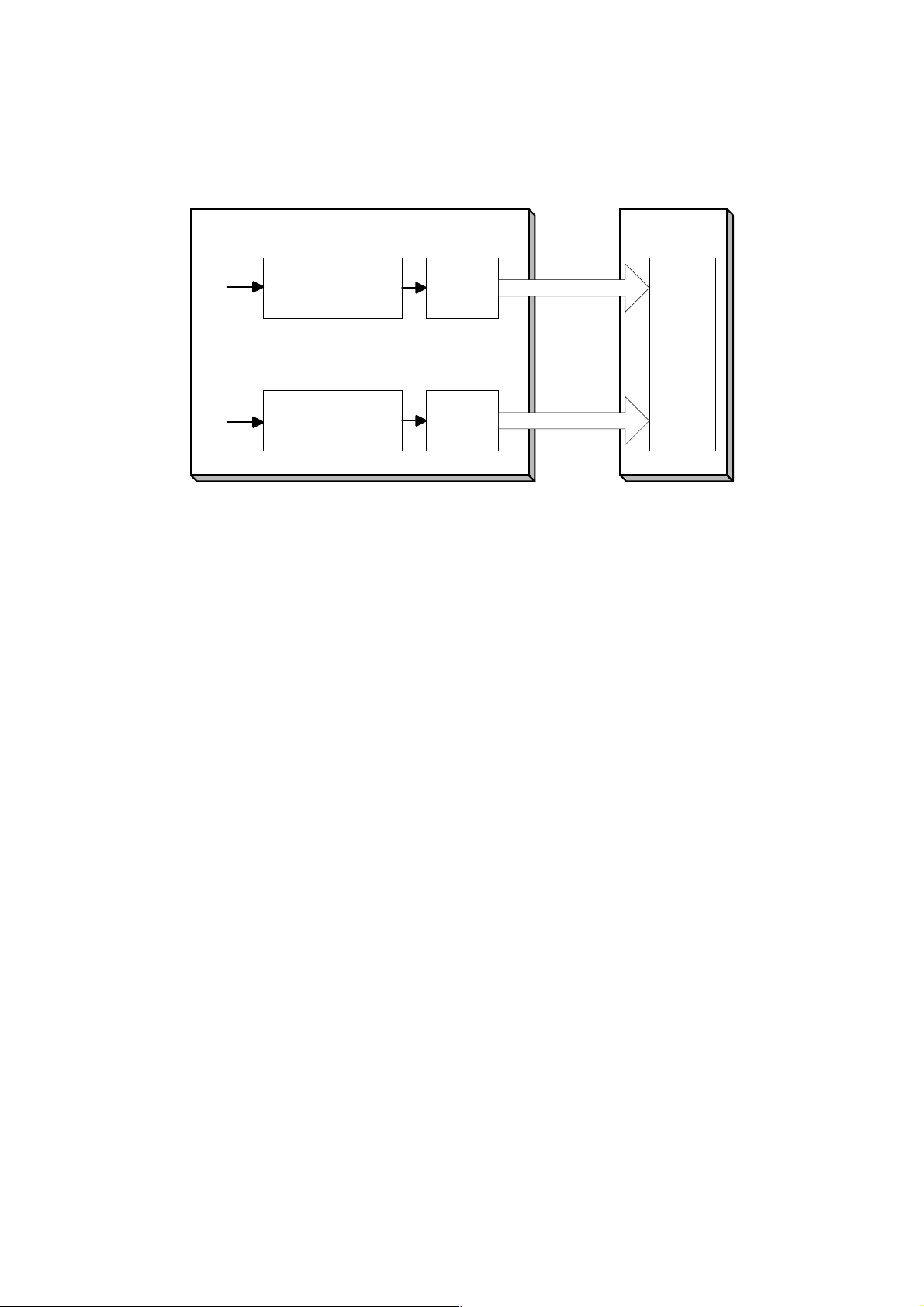
IMAGE PROCESSING
g
g
2.2.2 SBU (SENSOR BOARD UNIT)
O
Analo
Processing IC1
SBU
A/D 1
8 bit data
IPU
IPU-A
CCD
E
Analo
Processing IC2
A/D 2
8 bit data
B027D505.WMF
The CCD converts the light reflected f rom the original into an analog signal. The
CCD line has 7,450 pixels and the resolutio n is 6 00 dpi (23.6 lines/mm).
The CCD has two output lines, for odd and even pixels, to the analog processing
IC. The analog processing IC performs the following operations on the signals from
the CCD:
1. Z/C (Zero Clamp):
Adjusts the black level reference for even pixels to match the odd pixels.
2. Signal Amplification:
The analog signal is amplified by operational amplifiers in the AGC circuit.
3. Auto Gain Control
Adjusts the gain curve for the scanned image density.
After the above processing, the analog signals are converted to 8-bit signals by the
A/D converter. This will give a value for each pixel on a scale of 256 grades. Then,
the digitized image data goes to the IPU board.
B022/B027 2-6 SM
Page 67

2.2.3 AUTO IMAGE DENSITY
IMAGE PROCESSING
0.5mm
Sub scan direction
[A]
20mm
80mm
B027D552.WMF
ADS prevents the background of an original from appearing on copies.
The copier scans the auto image density detection area [A] as shown in the
diagram. This corresponds to a few mm at one end of the main scan line. As the
scanner scans down the page, the SBU detects the peak white level for each scan
line. The IPU performs the ADS function in accordance with the peak white level.
Detailed
Descriptions
When an original with a gray background is scanned, the density of the gray area
is the peak white level density. Therefore, the original background will not appear
on copies. Because peak level data is taken for each scan line, ADS corrects for
any changes in background density down the page.
As with previous digital copiers, the user can select manual image density when
selecting auto image density mode, and the machine will use both settings when
processing the original.
SM 2-7 B022/B027
Page 68

IMAGE PROCESSING
2.2.4 IPU (IMAGE PROCESSING UNIT)
Overview
SBU
LDD
IPU-A
IPU-B
Fax (FCU Board)
PCI BUS
Controller
Printer/Scanner
VCU
FCI
Video
Controller
IPU
SIMAC
HDD
B027D507.WMF
The image data from the SBU goes to the IPU (Image Processing Unit) ICs on the
SBCU board, which carry out the following processes on the image data.
IPU-A
•
Auto shading
•
Pre-filtering
•
Magnification
•
Test pattern generation
IPU-B
•
Filtering (MTF and smoothing)
•
ID gamma correction
•
Grayscale processing
•
Binary picture processing
•
Error diffusion
•
Dithering
Video Controller
•
Video path control
The image data then goes to the LD driver (LDD).
B022/B027 2-8 SM
Page 69

IMAGE PROCESSING
Image Processing Modes
The user can select one of the following modes with the User Tools screen: Text,
Text/Photo, Photo, Pale, Generation. Each of these modes has a range of different
settings (e.g. Soft, Normal, Sharp, etc). For each mode, a Custom Setting option is
also available. This Custom Setting holds the values selected with the SP modes,
which can be adjusted to meet special requirements that cannot be covered by the
standard settings.
To display this screen, press User Tools/Counter
, press Copier/Document
Server Settings, press the General Features tab, and then press Copy Quality.
B027D800.WMF
Mode Function
Text
Text/Photo
Photo Best possible reproduction of photographs. ( p.2-12 Photo Mode)
Pale
Generation
Copy
Best reproduction of text and sharp lines. Ignores background
texture. (
Good reproduction of mixed text and photographs with accurate
grayscaling, better than that achieved in the Text mode. ( p.2-13
Text/Photo Mode)
Reproduction similar to text mode, but of lower contrast. Ideal for
copying thin originals. ( p.2-14 Pale Mode)
Attempts to achieve the best reproduction of copied originals that
are faded because they are copies of copies. ( p.2-15 Generation
Copy)
p.2-11 Text Mode)
Detailed
Descriptions
In addition, there are two main image processing modes: grayscale processing and
binary picture processing. When the optional hard disk has not been installed, the
machine uses binary picture processing. However, when the optional hard disk has
been installed, the machine uses grayscale processing. The user or technician
cannot select the mode.
SM 2-9 B022/B027
Page 70

IMAGE PROCESSING
g
g
g
g
g
g
Image Processing Path
Overview
This diagram shows the various stages of the image process and where they are
done.
SBU
• ADS
IPU
IPU-A
• Auto Shadin
• Pre-Filterin
• Magnification
• Characteristic Detection
IPU-B
• Filterin
• ID Gamma Correction
• Error Diffusion
• Ditherin
• Binary Picture Processin
• Grayscale Processin
Video Path Control
LD Unit
HDD
Printer/
Scanner
• Memory Control
• Compression
Controller
Fax Unit
B027D559.WMF
B022/B027 2-10 SM
Page 71

IMAGE PROCESSING
SP Modes for Each Image Processing Step
The following tables show which settings and SP modes are used for each image
processing step.
Text Mode
Text Mode
Soft Normal Sharp
ADS (SBU) As selected at the operation panel
Shading
Correction
Small
Smoothing Filter
Main Scan
Magnification
Mirroring
Characteristic
Detection
MTF/Smoothing
Filter
Independent Dot
Erase
Background
Erase
Correction
γ
Gradation
Line Width
Correction
~34%
35%~
~34% Three-line filter
35%~ One-line filter
~34%
35%~
~34%
35%~
~34% None
35%~ Weak Middle Strong 4-903-2 ~ 4
~34% MTF (Weak)
35%~
~34% None
35%~ None
~34% None
35%~ None
~34% Text
35%~ Character (Text)
~34% Normal error diffusion
35%~ Character error diffusion
~34%
35%~
Character
(Weak)
Enabled only in the ADF mode
(Medium)
Character
(Medium)
MTF
Enabled
Enabled
MTF (Strong) 4-903-1
Character
(Strong)
Binary
picture
processing
Binary
picture
processing
2-907-1
Custom
Setting
4-903-2 ~ 4
4-904-1
4-904-6
4-904-11
4-903-1
4-903-2 ~ 4
Detailed
Descriptions
SM 2-11 B022/B027
Page 72

IMAGE PROCESSING
Photo Mode
Photo Mode
Coarse Print Print Photo
ADS (SBU) As selected at the operation panel
Shading
Correction
Small
Smoothing Filter
Main Scan
Magnification
Mirroring
Characteristic
Detection
MTF/Smoothing
Filter
Independent Dot
Erase
Background
Erase
Correction
γ
Gradation
Line Width
Correction
~34%
35%~
~34% Three-line filter
35%~ One-line filter
~34%
35%~
~34%
35%~
~34% None
35%~ None 4-903-6 ~ 8
~34% Character Smoothing 4-903-5
35%~ Smoothing Character 4-903-6 ~ 8
~34% None
35%~ None
~34% None
35%~ None
~34%
35%~
~34%
35%~
~34%
35%~
Dither
(16x16)
Dither
(16x16)
Enabled only in the ADF mode
Dither (8x8)
Dither (8x8)
Enabled
Enabled
2-907-2
Glossy
Photo
Dither
(Character)
Normal error
diffusion
Character
error
diffusion
Custom
Setting
4-904-2
4-904-7
4-904-12
4-903-5
4-903-6 ~ 8
B022/B027 2-12 SM
Page 73

IMAGE PROCESSING
Text/Photo Mode
Text/Photo Mode
Photo
Priority
ADS (SBU) As selected at the operation panel
Shading
Correction
Small
Smoothing Filter
Main Scan
Magnification
Mirroring
Characteristic
Detection
MTF/Smoothing
Filter
Independent Dot
Erase
Background
Erase
Correction
γ
Gradation
Line Width
Correction
~34%
35%~
~34% Three-line filter
35%~ One-line filter
~34%
35%~
~34%
35%~
~34% None
35%~
Strong Middle Weak 4-903-10 ~
~34% MTF (Weak)
35%~
Character
(Weak)
~34% None
35%~ None
~34% None
35%~ None
~34% Text/Photo
35%~ Character (Text/Photo)
~34% Normal error diffusion
35%~ Character error diffusion
~34%
35%~
Normal Text Priority
Enabled
Enabled
Enabled only in the ADF mode
MTF
(Medium)
Character
(Medium)
MTF (Strong) 4-903-9
Character
(Strong)
2-907-3
Custom
Setting
Detailed
Descriptions
12
4-903-10 ~
12
4-904-3
4-904-8
4-904-13
SM 2-13 B022/B027
Page 74

IMAGE PROCESSING
Pale Mode
Pale Mode
Photo
Priority
ADS (SBU) As selected at the operation panel
Shading
Correction
Small
Smoothing Filter
Main Scan
Magnification
Mirroring
Characteristic
Detection
MTF/Smoothing
Filter
Independent Dot
Erase
Background
Erase
Correction
γ
Gradation
Line Width
Correction
~34%
35%~
~34% Three-line filter
35%~ One-line filter
~34%
35%~
~34%
35%~
~34% None
35%~
~34% MTF (Weak)
35%~
~34% None
35%~ None
~34% None
35%~ None
~34% Pale
35%~ Character (Pale)
~34% Normal error diffusion
35%~ Character error diffusion
~34%
35%~
Weak Middle Strong 4-903-14 ~
Character
(Weak)
Normal Text Priority
Enabled
Enabled
Enabled only in the ADF mode
MTF
(Medium)
Character
(Medium)
MTF (Strong) 4-903- 13
Character
(Strong)
2-907-4
Custom
Setting
16
4-903-14 ~
16
4-904-4
4-904-9
4-904-14
B022/B027 2-14 SM
Page 75

IMAGE PROCESSING
Generation Copy
Generation Copy Mode
Photo
Priority
ADS (SBU) As selected at the operation panel
Shading
Correction
Small
Smoothing Filter
Main Scan
Magnification
Mirroring
Characteristic
Detection
MTF/Smoothing
Filter
Independent Dot
Erase
Background
Erase
Correction
γ
Gradation
Line Width
Correction
~34%
35%~
~34% Three-line filter
35%~ One-line filter
~34%
35%~
~34%
35%~
~34% None
35%~
Weak Middle Strong 4-903-18 ~
~34% MTF (Weak)
35%~
Character
(Weak)
~34% Weak
35%~ Weak
~34% Weak
35%~ Weak
~34% Generation copy
35%~ Character (Generation copy)
~34% Normal error diffusion
35%~ Character error diffusion
~34%
35%~
Normal Text Priority
Enabled
Enabled
Enabled only in the ADF mode
MTF
(Medium)
Character
(Medium)
MTF (Strong) 4-903- 17
Character
(Strong)
2-907-5
Custom
Setting
Detailed
Descriptions
20
4-903-18 ~
20
4-904-5
4-904-10
4-904-15
SM 2-15 B022/B027
Page 76

IMAGE PROCESSING
Auto Shading
Auto shading does two things.
•
Zeroes the black level for each scan line of data.
•
Corrects for variations in white level across the main scan.
Pre-Filtering
Pre-filter smoothes mainly parallel lines in the main scan direction and extended
lines in the sub-scan direction. This reduces moiré and spurious noise in images.
Main Scan Magnification/Reduction
Changing the scanner speed enables reduction and enlargement in the sub-scan
direction. However, the IPU-A chip handles reduction and enlargement in the main
scan direction. The processing for main scan magnification/reduction is the same
as in the previous digital machines.
Mirroring for ADF Mode
[A]
B027D564.WMF
When makin g a copy using the AD F, the magnifica tion circuit creates a mirror
image. This is because the scanning starting position in the main scan direction is
at the other end of the scan line in ADF mode (compared with platen mode). In
platen mode, the original is placed face down on the exposure glass, and the
corner at [A] is at the start of the main scan. The scanner moves down the page. In
ADF mode, the ADF feeds the leading edge of the original to the DF exposure
glass, and the opposite top corner of the original is at the main scan start position.
To create the mirror image, the IPU-A stores each line in a LIFO (Last In First Out)
memory.
B022/B027 2-16 SM
Page 77

IMAGE PROCESSING
Characteristic Detection
This function uses software filter s to detect edg e areas, non- edge areas, and areas
of shaded dot patterns.
The result determines the image processing tha t will be applied to each pixel.
Filtering
Overview
There are some software filters for enhancing the desired image qualities of the
selected original mode. These filters are the MTF filter, the smoothing filter,
characteristic filter, and independent dot erase.
Depending on the original mode and the reproduction ratio, the machine will use
either MTF/smoothing, or the filter determined by characteristic detection.
If MTF/smoothing is used, it is applied to all areas of the original, regardless of
whether they are edge areas, non-edge areas, or independent dots.
•
The MTF filter emphasizes sharpness and is used in all original types except
Photo mode.
•
The smoothing filter is used in Photo mode.
Detailed
Descriptions
If the characteristic filter is used, the filter for each pixel depends on the image data
type that was detected by characteristic detection.
MTF Filter
An MTF filter is used for all original types except Photo mode.
When the reproduction ratio is less than 35%, this filter is applied to all image data
pixels, regardless of whether they are in an edge area or non-edge area.
When the reproduction ratio is 35% or more, the type of MTF filter used for each
pixel depends on the results of characteristic detection.
Smoothing Filter
A smoothing filter is used in Photo mode instead of MTF. It is applied to all image
data pixels, regardless of whether they are in an edge area or non-edge area.
With some combinations of reproduction ratio and image mode, the type of
smoothing used for each pixel depends on the results of characteristic detection
(see the Photo mode table in SP Modes for Each Processing Step).
Characteristic Filter
A characteristic filter is applied instead of MTF, smoothing, and ID gamma
correction with some combinations of original type and reproduction ratio. See the
‘SP Modes for Each Processing Step’ section.
For example, In text mode, for the ‘Normal’ original type, if the reproduction ratio is
less than 35%, MTF (medium) is used for all pixels in the image. However, if the
reproduction ratio is 35% or more, the ‘medium’ characteristic filter is used, and the
processing depends on whether the pixel was in an edge area, a non-edge area, or
in an area shaded using a dot pattern.
SM 2-17 B022/B027
Page 78

IMAGE PROCESSING
Each characteristic filter consists of a combination of the following features: MTF,
smoothing, error diffusion, dithering, ID gamma correction. For each of these
features, the machine chooses from two types when making up a characteristic
filter.
Independent Dot Erase
Independent dot erase removes unwanted dots from the image.
Independent dot erase is enabled only for Generation Copy mode (according to the
default settings). However, for the “Custom Setting” original modes, independent
dot detection can be enabled and adjusted with SP4-904-2~4. With a larger SP
setting, more dots are detected as independent dots and erased, even if the dot
density is high. However, dots in mesh-like images may be mistakenly detected as
independent dots.
Background Erase
By default, this process is disabled in all original modes. However, it can be
enabled with SP mode.
Usually, dirty background is erased using the Auto Image Density (ADS) function.
However, sometimes, dirty background areas will still appear. These can be erased
with this function.
The threshold level for erasing can be changed with SP4-904-6~10.
ID Gamma (γ) Correction
The machine automatically selects the most appropriate ID gamma correction
based on the selected original type.
Also, for certain combinations of reproduction ratio and original type, characteristic
detection is used. In this case, the machine can use one of two gamma correction
tables. The one that is used is decided separately for each pixel, and depends on
the results of characteristic detection.
Gradation Processing
Overview
There are four types of gradation processing:
Grayscale processing: This has 4 output levels for each pixel.
•
Binary picture processing: This has only two output levels (black and white).
•
Error diffusion: There are two error diffusion processing types (normal and
•
characteristic detection)
Dithering: There are two dithering processing types (normal and characteristic
•
detection).
B022/B027 2-18 SM
Page 79

IMAGE PROCESSING
Grayscale Processing
In this machine, the 8-bit image data is converted into 2-bit data. This produces up
to 4 image density levels for each pixel.
To realize this, this machine uses a form of pulse width modulation. In this
machine, pulse width modulation consists of the following processes:
•
Laser diode pulse positioning
•
Laser diode power/pulse width modulation
Laser diode power and pulse width modulation is done by the laser diode drive
board (LDD). Briefly, the width of the laser pulse for a pixel depends on the output
level (image density level: from 0 to 255) required for the pixel.
Note that although the LDD can create 256 levels per pixel, the machine only uses
8 of these, and only four are used for any one job. A gamma table determines
which four output levels are used. The gamma table is different for each original
type setting.
Binary Picture Processing
The 8-bit image data is converted into 1-bit data (black and white image data).
Error Diffusion
The error diffusion process reduces the difference in contrast between light and
dark areas of a halftone image. Each pixel is corrected using the difference
between it and the surrounding pixels. The corrected pixels are compared with an
error diffusion matrix.
There are two types of error diffusion processing: One is ‘normal’. The other is part
of the characteristic detection process, in which the error diffusion method is
determined separately for each pixel. The error diffusion type (normal or
characteristic) depends on the reproduction ratio and the original type (refer to the
SP Modes for Each Image Processing Step tables).
Detailed
Descriptions
Dithering
Each pixel is compared with the pixel in the same position in a dither matrix.
Several matrixes are available, to increase or decrease the detail on the copy.
Line width correction
This function is effective in all original modes.
Usually, lines will bulge in the main scan direction as a result of the
negative/positive development system that is used in this model. So, pixels on
edges between black and white areas are compared with adjacent pixels, and if the
pixel is on a line, the line thickness will be reduced.
Line width correction is done in the VCU chip on the LDD board.
The line width correction type can be selected with SP2-907.
SM 2-19 B022/B027
Page 80

IMAGE PROCESSING
2.2.5 VIDEO CONTROL UNIT (VCU)
Fine Character and Image (FCI)
The FCI circuit performs image smoothing.
4/4 3/4 2/4 1/4 0
Sub Scan
Fig. A
Fig. B
Direction
Main Scan Direction
Fig. C
B027D574.WMF
Usually, binary picture processing generates jagged edges on characters, as
shown in the above illustration. These are reduced using edge smoothing. The FCI
changes the laser pulse duration and position for certain pixels.
Fig. A shows the four possible pulse durations, and Fig. B shows how the laser
pulse can be in one of three positions within the pixel. Fig. C shows an example of
how edge smoothing is used.
This function only affects the received image for fax mode and for printer mode,
even if copy mode is also using binary picture processing.
B022/B027 2-20 SM
Page 81

2.3 LASER EXPOSURE
2.3.1 OVERVIEW
[H]
[A]
[I]
[C]
[D]
[B]
LASER EXPOSURE
Detailed
Descriptions
[F]
[G]
[E]
B027D101.WMF
The optical path from the laser diode to the drum is shown above.
The LD unit [A] outputs a laser beam to the poly g on mirr or [B] throug h the
cylindrical lens [C]. The shield glass [D] prevents dust from reaching the polygon
mirror.
Each surface of the polygon mirror reflects one full main scan line. The laser beam
goes to the F-theta mirror [E], mirror [F], and BTL (barrel toroidal lens) [G]. Then
the laser beam goes to the drum through the toner shield glass [H].
The laser synchronizing detector [I] determines the main scan starting position.
The speed of the polygon mirror motor is 28,818.9 rpm for 600 dpi.
SM 2-21 B022/B027
Page 82
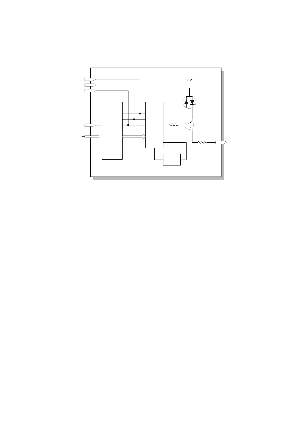
LASER EXPOSURE
2.3.2 AUTO POWER CONTROL (APC)
LD LEVEL
LD ON
LD OFF
LD OFF
VIDEO
LD
Controller
LD Drive Board
VIDEO
LD Driver
LD
VREF
Reference
Circuit
+5V
PD LD
Monitor
B027D510.WMF
The LD driver IC drives the laser diode. To prevent the intensity of the laser beam
from changing because of the temperature, the machine monitors the current
passing through the laser diode (LD). The machine adjusts the current to the laser
diode by comparing it with the reference level from the reference circuit.
This auto power control is done just after the machine is turned on and during
printing while the laser diode is active.
The laser diode power is adjusted on the production line.
NOTE:
Do not touch the variable resistors on the LD unit in the field.
B022/B027 2-22 SM
Page 83

2.3.3 LD SAFETY SWITCH
Front Cover Safety and
Right Cover Switches
LASER EXPOSURE
LDD:
+5VLD+5VLD
LD Drive Board
SBCU
+5V
PSU
IPU
VCC
LD Driver IC
PD
LD
Laser
Beam
Optical Path
OPC
Drum
B027D500.WMF
To ensure technician and user safety and to prevent the laser beam from
inadvertently switching on during servicing, safety switches are located at the front
and right covers. The switches are installed on the +5VLD line coming from the
power supply unit through the SBCU and IPU boards.
When the front cover or t he right cover is opened, the power supply to the laser
diode is interrupted.
Detailed
Descriptions
SM 2-23 B022/B027
Page 84

PHOTOCONDUCTOR UNIT (PCU)
2.4 PHOTOCONDUCTOR UNIT (PCU)
2.4.1 OVERVIEW
1
2
3
10
4
9
5
8
7
B022D251.WMF
6
The PCU consists of the components shown in the above illustration. An organic
photoconductor (OPC) drum (diameter: 30 mm) is used in this machine.
1. Cleaning Blade
2. Toner Collection Coil
3. Pick-off Pawl
4. OPC Drum
5. ID Sensor (see note)
NOTE:
These parts are not included in the PCU.
6. Development Roller
7. Development Unit
8. Charge Roller
9. Charge Roller Cleaning Roller
10. Quenching Lamp (see note)
The machine informs the user when the PCU life has finished. However, the user
can continue to make copies.
SP5-912 can be used to enable or disable this warning message, and to change
the default replacement interval (the default is 60k).
B022/B027 2-24 SM
Page 85

2.4.2 DRIVE
[B]
PHOTOCONDUCTOR UNIT (PCU)
[A]
[E]
[C]
[D]
B027D202.WMF
Detailed
Descriptions
The main motor [A] drives the drum [B] through a series of gears, a timing belt [C],
and the drum drive shaft [D]. The main motor assembly includes a drive controller,
which outputs a motor lock signal when the rotation speed is out of the specified
range.
The fly-wheel [E] on the end of the drum drive shaft stabilizes the rotation speed
(this prevents banding and jitter from appearing on copies).
SM 2-25 B022/B027
Page 86

PHOTOCONDUCTOR UNIT (PCU)
2.4.3 NEW PCU DETECTION
[A]
B027D206.WMF
[B]
[C]
The new PCU detect switch [A] detects when a new PCU is installed. Each PCU
has an actuator [B]. When a new PCU is installed in the machine, the actuator [B]
pushes the new PCU detect switch. The actuator is a sector gear, and this gear
engages with the drum gear [C]. When the drum rotates, the actuator is released
from the drum gear. The actuator drops away from the new PCU detect switch and
remains in this "down" position for the duration of the PCU's life.
The machine recognizes when a new PCU has been installed in the machine
because the actuator of the new PCU contacts the new PCU detect switch. After
the front cover and right cover are closed, the machine then performs the TD
sensor initial setting procedure automatically (for about 45 seconds). During this
time, the drum rotates and the actuator drops away from the sensor.
Also, while the machine performs the TD sensor initial setting, the machine makes
a ID sensor pattern on the drum. This checks whether the developer has fallen into
the development unit (in other words, it checks whether the technician remembered
to remove the developer seal from the PCU at machine installation). If the machine
does not detect the ID sensor pattern, SC 392 will be generated.
B022/B027 2-26 SM
Page 87

2.5 DRUM CHARGE
2.5.1 OVERVIEW
DRUM CHARGE
[D]
[C]
[A]
[B]
B027D203.WMF
This copier uses a drum charge roller to charge the drum. The drum charge roller
[A] always contacts the surface of the drum [B] to give it a negative charge of
-900V.
Detailed
Descriptions
The high voltage supply board gives a negative dc voltage to the drum charge
roller through the spring [C] and terminal plate [D].
SM 2-27 B022/B027
Page 88

DRUM CHARGE
2.5.1 CHARGE ROLLER VOLTAGE CORRECTION
Correction for Environmental Conditions
ID Sensor Pattern
Charge Voltage
Laser Diode
Drum Potential
Development Bias
ID Sensor Output
On
Off
[A]
2 cm
2 cm
28.9 cm
+
[B]
Sub Scan Direction
-1700 V
-1500 V
-950 V
-750 V
-650 V
-400 V
-150 V
V sg (4.00 V)
V sdp (3.70 V)
V sp (0.40 V)
t
B027D508.WMF
With a drum charge roller system, the voltage transferred from roller to drum varies
with the temperature and humidity around the drum charge roller. The lower the
temperature or humidity is, the higher the applied voltage required.
To compensate, the machine uses the ID sensor to measure the effects of current
environmental conditions. For this measurement, the process control parameters
are balanced so that any small change in drum potential caused by environmental
effects is reflected in a change in the amount of toner transferred to the drum.
This measurement is made immediately after the ID sensor pattern for toner
density control. Immediately after making ID sensor pattern [A], the charge roller
voltage stays on, but the development bias goes up to -650V; as a result the drum
potential is reduced to -750V. The laser diode is not switched on, and the drum
potential is now slightly higher than the development bias, so only a very small
amount of toner transfers to the drum. The ID sensor measures the density of this
pattern [B], and the output voltage is known as Vsdp. This voltage is compared with
Vsg (read from the bare drum at the same time).
B022/B027 2-28 SM
Page 89

DRUM CHARGE
If the humidity drops, the drum potential goes up (to a higher –ve voltage) even if
the charge roller voltage supply stays the same (efficiency of voltage transfer is
higher with lower humidity). As a result, less toner is transferred to ID sensor
pattern [B]. If the sensor output reaches a certain point, the drum charge voltage
will be reduced.
To determine whether to change the drum charge roller voltage, the machine
compares Vsdp with Vsg.
•
Vsdp / Vsg > 0.95 = Reduce the magnitude of the drum charge voltage by 50 V
•
Vsdp / Vsg < 0.90 = Increase the magnitude of the drum charge voltage by 50 V
2.5.2 ID SENSOR PATTERN PRODUCTION TIMING
The ID sensor pattern is made in the following conditions:
•
During warming up at power on
•
If the machine starts warming up after a certain time (default: 30 minutes) has
passed since entering night mode or low power mode
The 30-minute interval can be changed using SP2995-1.
•
At the end of a job, if an ID sensor pattern has not been made for a certain
number of sheets (default: 0 sheets = disabled)
The number of sheets can be changed using SP2995-2.
Detailed
Descriptions
SM 2-29 B022/B027
Page 90

DRUM CHARGE
2.5.3 DRUM CHARGE ROLLER CLEANING
[B]
[A]
B022D252.WMF
Because the drum charge roller [A] always contacts the drum, it gets dirty easily.
So, the charge roller cleaning roller [B] also contacts the drum charge roller all the
time to clean the surface of the drum charge roller.
B022/B027 2-30 SM
Page 91

2.6 DEVELOPMENT
2.6.1 OVERVIEW
5
DEVELOPMENT
Detailed
Descriptions
1
4
B027D301.WMF
3
2
The development unit consists of the following parts.
1. Development roller
2. Mixing auger 2
4. Mixing auger 1
5. Doctor blade
3. TD sensor
This machine uses a single-roller development system. Two mixing augers mix the
developer. The toner density (TD) sensor and image density (ID) sensor (see the
illustration in the PCU section) are used to control toner density.
SM 2-31 B022/B027
Page 92

DEVELOPMENT
2.6.2 DRIVE
[C]
[A]
[B]
[D]
B027D304.WMF
The main motor [A] drives the development roller [B] and mixing augers [C] through
a train of gears and the development drive shaft [D]. When the PCU is pushed in,
the development drive shaft engages the development roller gear.
The development drive gears (except for the gears in the development unit) are
helical gears. These gears are quieter than normal gears.
B022/B027 2-32 SM
Page 93

2.6.3 DEVELOPER MIXING
[D]
DEVELOPMENT
[C]
[A]
[B]
[B]
[A]
B027D302.WMF
This copier uses 2 mixing augers, [A] and [B], to keep the developer evenly mixed.
Mixing auger 2 [A] transports excess developer, scraped off the development roller
[C] by the doctor blade [D], towards the front of the machine. Mixing auger 1 [B]
returns the excess developer, along with new toner, to the rear of the mixing
assembly. Here the developer is reapplied to the development roller.
Detailed
Descriptions
SM 2-33 B022/B027
Page 94

DEVELOPMENT
2.6.4 DEVELOPMENT BIAS
[B]
[A]
B027D303.WMF
This machine uses a negative-positive development system, in which black areas
of the latent image are at a low negative charge (about –150 ± 50 V) and white
areas are at a high negative charge (about -950 V).
To attract negatively charged toner to the black areas of the latent image on the
drum, the high voltage supply board applies a bias of -650 volts to the development
rollers throughout the image development process. The bias is applied to the
development roller shaft [A] through the drive shaft [B].
The development bias voltage (-650 V) can be adjusted with SP2-201-1.
B022/B027 2-34 SM
Page 95
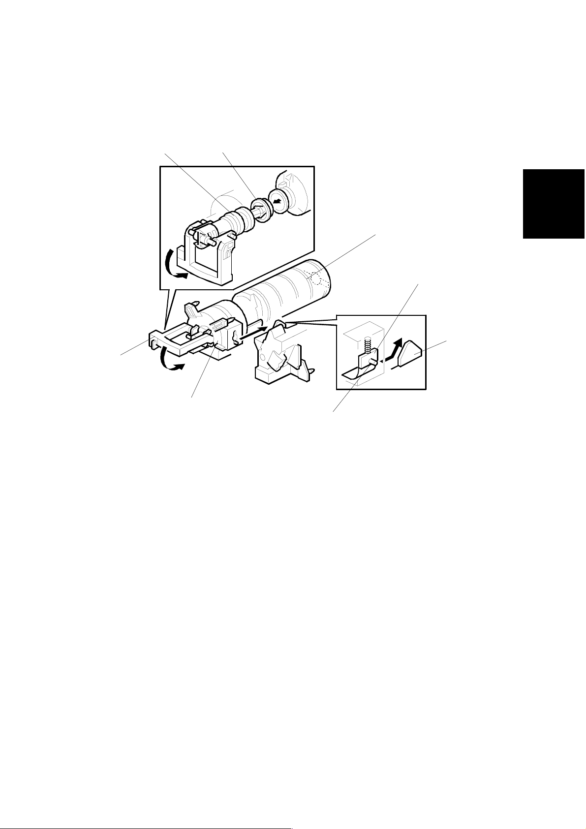
2.6.5 TONER SUPPLY
Toner bottle replenishment mechanism
DEVELOPMENT
[E]
[G]
[A]
[F]
[B]
[H]
[D]
B027D557.WMF
Detailed
Descriptions
[C]
When a toner bottle is placed in the bottle holder unit [A] and the unit is pushed in
completely, pin [B] moves against the side [C] of the PCU, and the toner shutter [D]
is pulled out to open the bottle. When the toner bottle holder lever [E] is put back in
the original position, the cap [F] on the toner bottle is pulled away and kept in place
by the chuck [G].
The toner supply mechanism transports toner from the bottle to the development
unit. The toner bottle has a spiral groove [H] that helps move toner to the
development unit.
When the bottle holder unit is pulled out to add a new toner bottle, the following
happens automatically to prevent toner from scattering.
•
The chuck releases the toner bottle cap into its proper position.
•
The toner shutter shuts to block the opening as a result of pressure from a
spring.
SM 2-35 B022/B027
Page 96
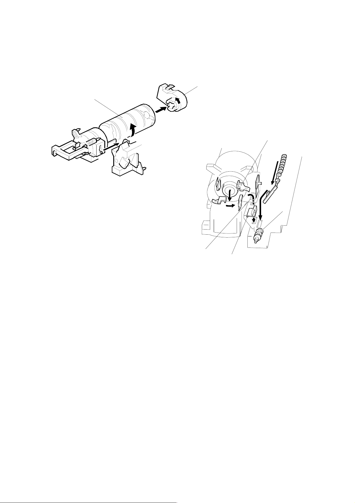
DEVELOPMENT
Toner supply mechanism
[B]
[A]
[C]
B027D558.WMF
[D]
[E]
B027D306.WMF
The toner supply motor [A] drives the toner bottle [B] and the mylar blades [C].
First, the toner falls down into the toner bottle holder. The toner supply mylar
blades transfer the toner to the slit [D]. When the PCU is installed in the machine,
the shutter [E] above the PCU is opened by the machine frame. Then the toner
falls down into the development unit through the slit and the shutter.
B022/B027 2-36 SM
Page 97

DEVELOPMENT
g
g
g
g
2.6.6 TONER DENSITY CONTROL
Overview
There are four modes for controlling toner supply as shown in the following tables.
The mode can be changed with by SP2-921. The factory setting is sensor control 1
mode.
Basically, toner density is controlled using the standard TD sensor voltage (Vts),
toner supply reference voltage (Vref), actual TD sensor output voltage (Vt), and ID
sensor output data (Vsp/Vsg).
Toner Supply Clutch On Time
Calculation
TD Sensor Output
(Vt)
Detailed
Descriptions
Vt Reference
Volta
e (Vref)
New Vref
Vt Reference
Volta
e Update
Vref Update
ID Sensor Output
(Vsp/Vs
TD Sensor Initial
Settin
)
(Vts)
B027D517.WMF
SM 2-37 B022/B027
Page 98

DEVELOPMENT
There are four toner density control modes as follows.
Mode
Sensor control 1 (SP2-921, “0”): Normally use this setting only
Toner supply decision Compare Vt with a reference voltage (Vts or Vref)
Toner control process
Toner is supplied to the development unit when Vt is higher
than the reference voltage (Vts or Vref). This mode keeps the
Vref value for use the next toner density control.
Vts is used for the first toner density control after a new PCU
has been installed, until it has been corrected with the ID
sensor output.
Vref is used after Vts has been corrected with the ID sensor
output voltage (corrected during the first toner density control
for a new PCU).
Toner supply amount Varies
Toner end detection Performed
Mode
Sensor control 2 (SP2-921, “1”): For designer’s use only; do
not use in the field
Toner supply decision Compare Vt with a reference voltage (Vts)
Toner control process T his toner control process is the same as sensor control 1
mode. However, the reference voltage used is always Vts.
Toner supply amount Varies
Toner end detection Performed
Mode
Fixed control 1 (SP2-921, “2”): For designer’s use only; do not
use in the field
Toner supply decision Compare Vt with a reference voltage (Vts or Vref)
Toner control process T his toner control process is the same as sensor control 1
mode.
Toner supply amount Fixed (SP2-925)
Toner end detection Performed
Mode
Fixed control 2 (SP2-921, “3”): Use temporarily if the TD
sensor needs to be replaced
Toner supply decision None
Toner control process T oner is supplied every printed page regardless of Vt.
Toner supply amount Fixed (SP2-925)
Toner end detection Not performed
B022/B027 2-38 SM
Page 99

DEVELOPMENT
Toner density sensor initial setting
The TD sensor initial setting procedure is performed automatically when the new
PCU is installed in the machine. During TD sensor initial setting, the TD sensor is
set so that the TD sensor output to the value of SP2-926 (default: 2.5V). This value
will be used as the standard reference voltage (Vts) of the TD sensor.
Toner density measurement
Toner density in the developer is detected once every copy cycle. The sensor
output voltage (Vt) during the detection cycle is compared with the standard
reference voltage (Vts) or the toner supply reference voltage (Vref).
Vsp/Vsg detection
The ID sensor detects the following voltages.
•
Vsg: The ID sensor output when checking the drum surface
•
Vsp: The ID sensor output when checking the ID sensor pattern
•
At the end of a job, if an ID sensor pattern has not been made for a certain
number of sheets (default: 0 sheets = disabled)
The number of sheets can be changed using SP2-995-2.
In this way, the reflectivity of both the drum surface and the pattern on the drum are
checked. This compensates for any variations in the reflectivity of the pattern on
the drum or the reflectivity of the drum surface.
The ID sensor pattern is made on the drum by charge roller and laser diode.
Vsp/Vsg is not detected every page or job; it is detected at the following times to
decide Vref .
•
During warming up at power on
•
If the machine starts warming up after a certain time (default: 30 minutes)
has passed since entering night mode or low power mode
The 30-minute interval can be changed using SP2-995.
Detailed
Descriptions
Toner supply reference voltage (Vref) determination
The toner supply reference voltage (Vref) is the threshold voltage for the toner
supply determination. Vref is determined using the following data:
•
ID sensor output (Vsp/Vsg)
•
(Vts or the curre nt Vref) - Vt
Toner supply determination
The reference voltage (Vts or Vref) is the threshold voltage for determining whether
or not to supply toner. If Vt becomes greater than the reference voltage, the
machine supplies additional toner.
SM 2-39 B022/B027
Page 100

DEVELOPMENT
Toner Supply Motor On Time Determinations
For fixed control mode, the toner supply motor on time is specified by the setting of
SP2-925, and does not vary. The default setting is 200 ms for each copy. The
toner supply motor on time for each value of SP2-925 is as follows.
Value of SP2-925 Motor On Time (t = 200 ms)
0t
12t
24t
38t
4 12t
5 16t
6 Continuously
7 Not supplied
For sensor control modes 1 and 2, the toner supply motor on time is decided by the
following factors.
• ∆
Vt (= Vt – (Vref or Vts))
•
TD sensor sensitivity (coefficient: S, value is 0.3)
There are seven levels for toner supply motor on time as shown below.
Level Decision Motor On Time (seconds)
1
2
3
4
5
6
7
NOTE:
0 < ∆Vt ≤ S/16
S/16 < ∆Vt ≤ S/8
S/8 < ∆Vt ≤ S/4
S/4 < ∆Vt ≤ S/2
S/2 < ∆Vt ≤ 4S/5
4S/5 < ∆Vt ≤ S (near-end)
S < ∆Vt (toner end)
1) The value of “t” can be changed using SP2-922 (default : 0.6 second)
t (0.6)
t x 2 (1.2)
t x 4 (2.4)
t x 8 (4.8)
t x 16 (9.6)
T (30); see note 3
T (30); see note 3
2) The value of “T” can be changed using SP2-923 (default: 30 seconds)
3) T (30) means that toner is supplied intermittently in a half duty cycle
(1.5 s on, 1.5 s off) for 30 seconds
B022/B027 2-40 SM
 Loading...