

Page 1
Technical Bulletin No. RTB-001
SUBJECT: F400/F410 Fusing unit modification (manual corrections) DATE:SEP.15.’93
PAGE: 1 of 6
PREPARED BY: S.MANO
CHECKED BY:
CLASSIFICATION:
Action Required
Troubleshooting
Retrofit Information
FROM: Copier Technical Support Group
MODEL: F400/F410
Revision of service manual
Information only
Other
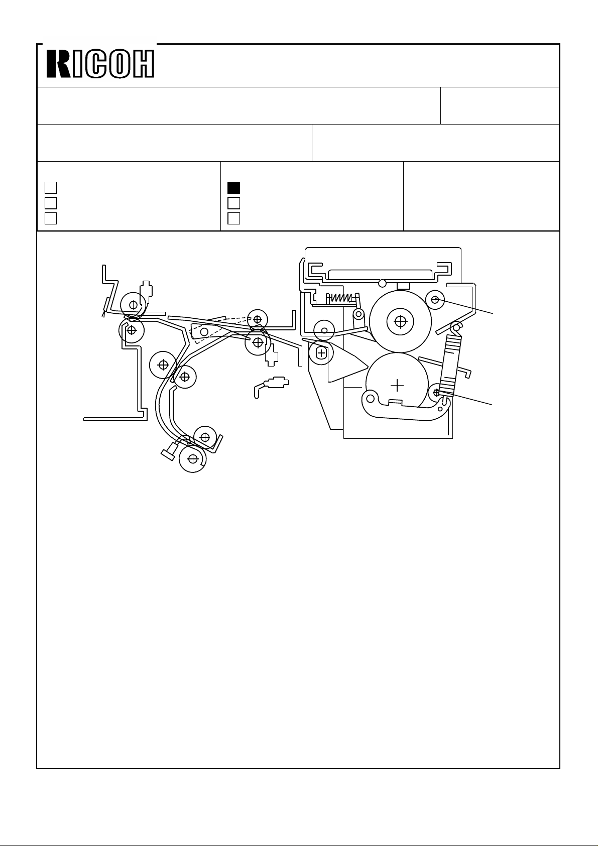
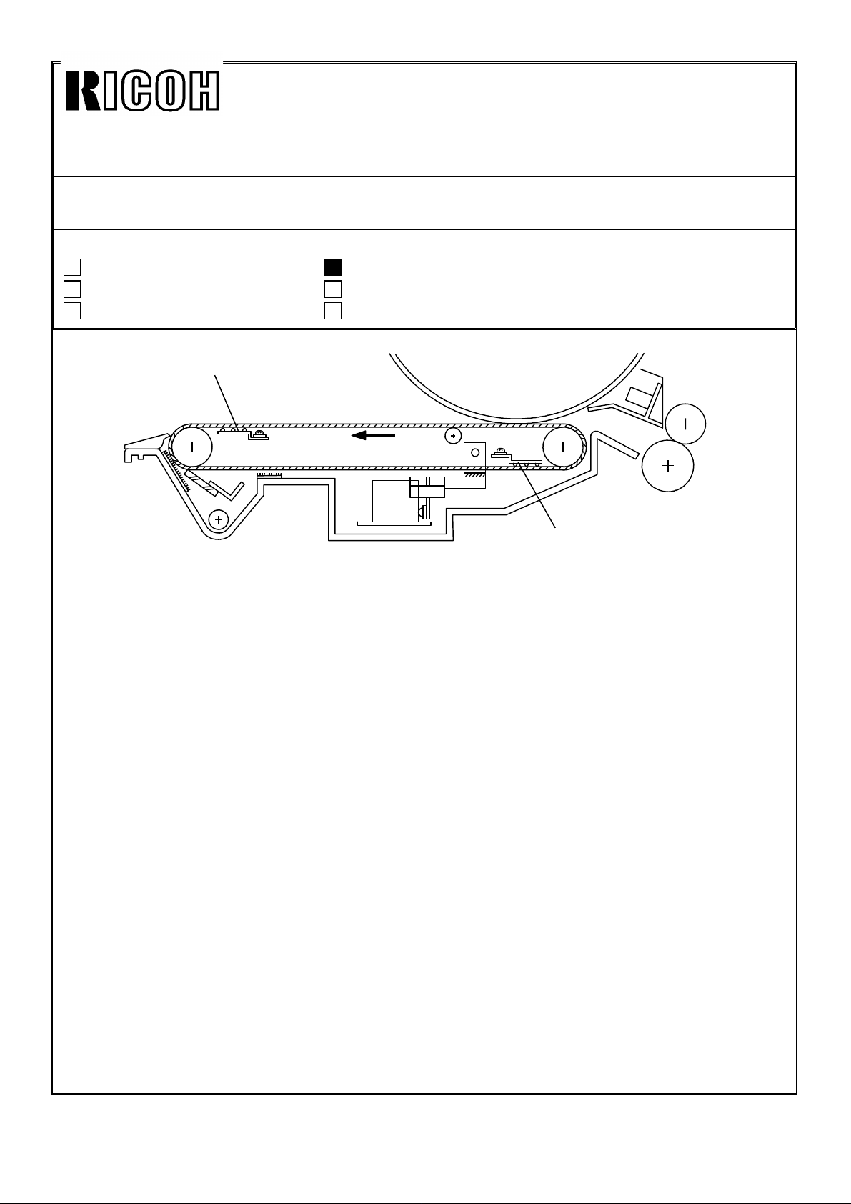
[A]
[B]
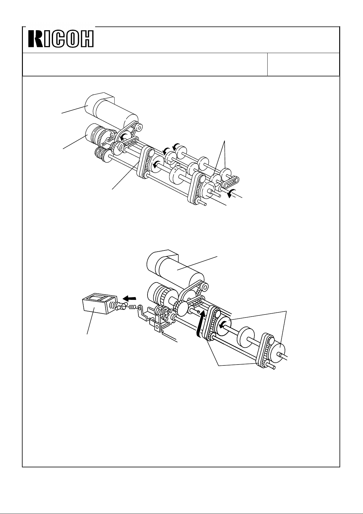
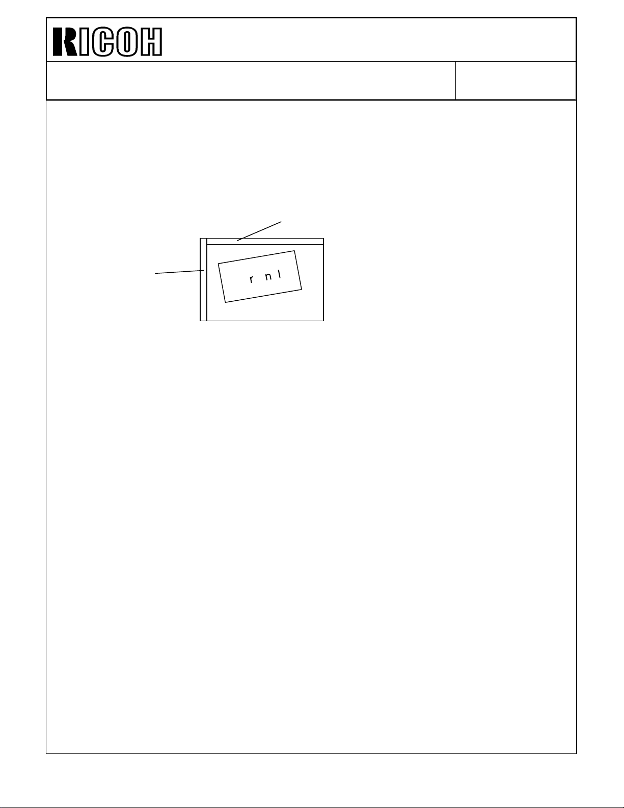
An oil supply roller [A] and a cleaning roller [B] are added in the fusing unit.
This modification is implemented from the first mass-production machine.
1. Oil supply roller
The oil supply roller touches the hot roller and applies a small amount of silicone oil to the
hot roller surface.
Purpose:
1) To prevent any foreign substance (ex. toner, paper powder) from adhering to the
hot roller surface.
2) To improve paper separation from the hot roller.
2. Cleaning roller
Purpose:
1. To clean the pressure roller surface.
Note: Both the oil supply roller and cleaning roller are PM parts. Please be sure to
replace them at every 120K copies.
Page 2
Technical Bulletin No. RTB-001
SUBJECT: F400/F410 Fusing unit modification (Manua corrections) DATE:SEP.15.’93
PAGE: 2 of 6
Manual corrections
Because of this modification, the following parts of the service manual should be corrected.
Section 2: DETAILED SECTION DESCRIPTIONS
P2-94: Please add two rollers to the overview illustration as shown by the illustration on
page 1 of this RTB.
Please delete the third paragraph "This model uses an oilless. . . . . ."
NEW Please add the attached "7.7 OIL SUPPLY" (attached - page 4 of this RTB)
Section 4: SERVICE TABLES
P4-5 Please add the following service remark as item No.4 of the 1.11 FUSING UNIT.
Level the oil supply roller while it is stored, otherwise the silicone oil in the oil supply roller
comes out from the lower part.
P4-58 Please change the Fusing Thermistor table as below.
EM 120K 240K 360K NOTE
Fusing
Thermistor
P4-59 Please add the following table to the PM table.
EM 120K 240K 360K NOTE
Oil Supply Roller R R R
Cleaning Roller R R R
CCC
Suitable solvent.
Refer to NOTE 6
P4-64 Please delete "Then apply small amount of silicone oil there every 240K copies."
from item (1) of NOTE 6: Fusing Section. This is because the oil supply roller
applies small amount of silicone oil. Just clean the thermistor at every PM.
Page 3

Technical Bulletin No. RTB-001
SUBJECT: F400/F410 fusing unit modification (Manual corrections) DATE:SEP.15.’93
PAGE: 3 of 6
P4-70 Please remove "and apply silicone oil." from the item 8-2 of the preventive
maintenance (PM) schedule.
Please add the following PM procedure as item No.8-4 and 8-5 of the PM
schedule.
8-4. Replace the oil supply roller.
8-5. Replace the pressure roller cleaning roller.
Section 5: REPLACEMENTS AND ADJUSTMENTS
P5-100 Please correct step 4 of procedure "7.5 HOT ROLLER REPLACEMENT" as
follows.
•
Original expression:
4. Remove the upper entrance guide [D] (1 screw).
•
Corrected expression
4. Remove the oil supply roller unit.
(Refer to Oil Supply Roller Replacement.)
This is because:
1) Since the oil supply roller is installed to the upper entrance guide, the upper
entrance guide is renamed as "cleaning roller unit".
2) No screw is used to install the cleaning roller unit to the fusing unit. (The upper
entrance guide used to be installed with a screw.)
Please delete the screw fixing part [D] from the illustration.
New Please add procedure "7.10 OIL SUPPLY ROLLER REPLACEMENT" (attached -
page 6 of this RTB) and "7.11 CLEANING ROLLER REPLACEMENT" (attached -
page 7 of this RTB).
Section 6: TROUBLESHOOTING
P 6-15 Please add the following sentence as a possible cause for SC520. (To prevent this
from occurring, replace the cleaning roller at every PM.)
Cleaning roller is too dirty and applies a great load to the fusing/duplex drive motor.
Page 4
Technical Bulletin No. RTB-001
SUBJECT: F400/F410 fusing unit modification (Manual corrections) DATE:SEP.15.’93
PAGE: 4 of 6
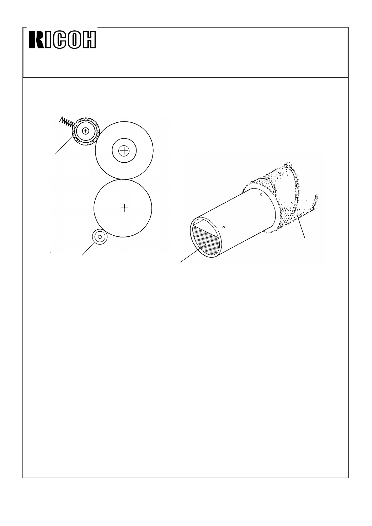
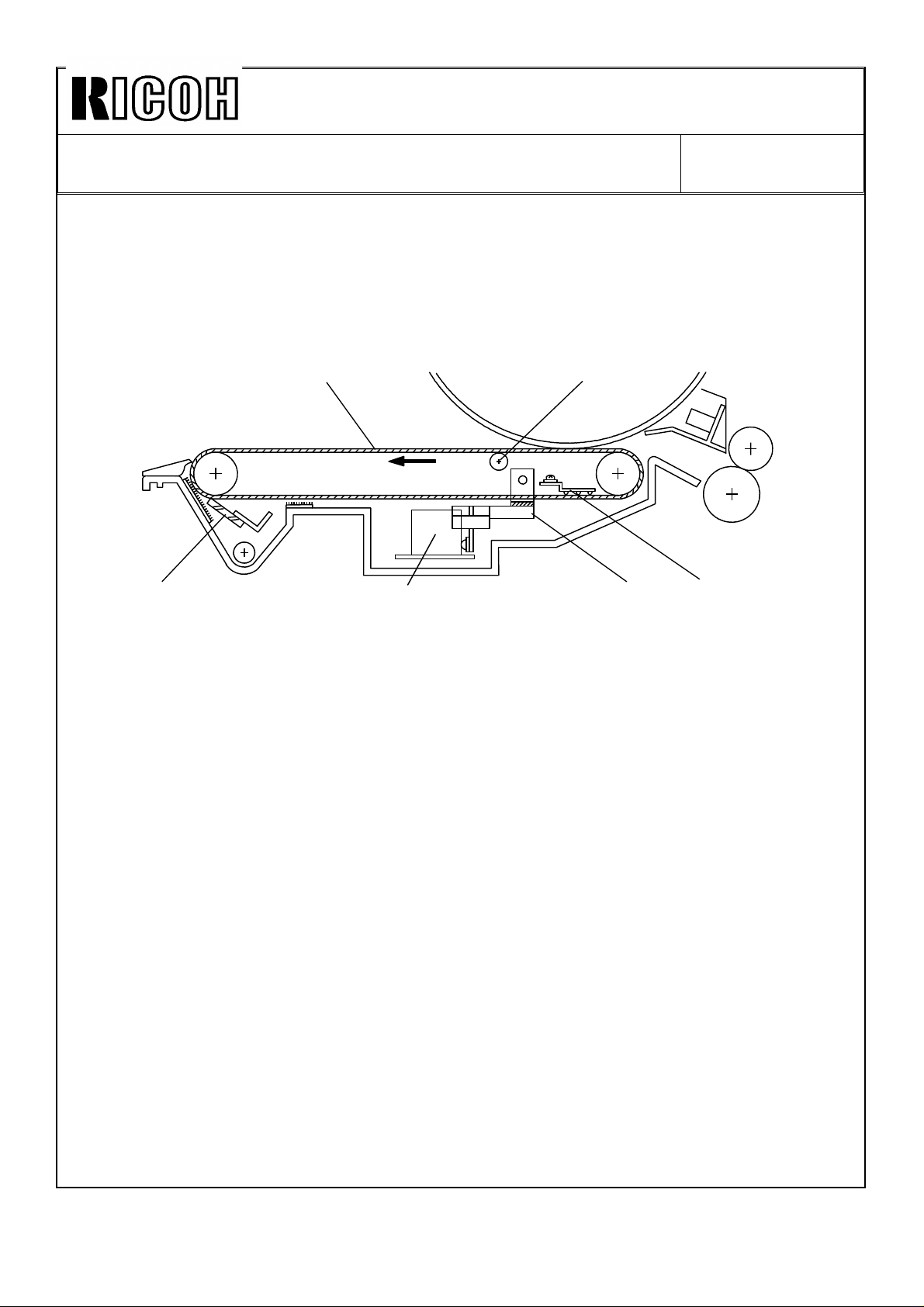
7.7 OIL SUPPLY AND CLEANING
[A]
[A]
[C]
The oil supply roller [A] is soaked with silicon oil [B]. The roller contacts the hot roller by a
spring. It turns with the hot roller and applies a light coat of silicon oil to the hot roller.
The cleaning roller [C] collects any foreign substance (toner, paper dust) on the pressure
roller.
[B]
Page 5

Technical Bulletin No. RTB-001
SUBJECT: F400/F410 fusing unit modification (Manual corrections) DATE:SEP.15.’93
PAGE: 5 of 6
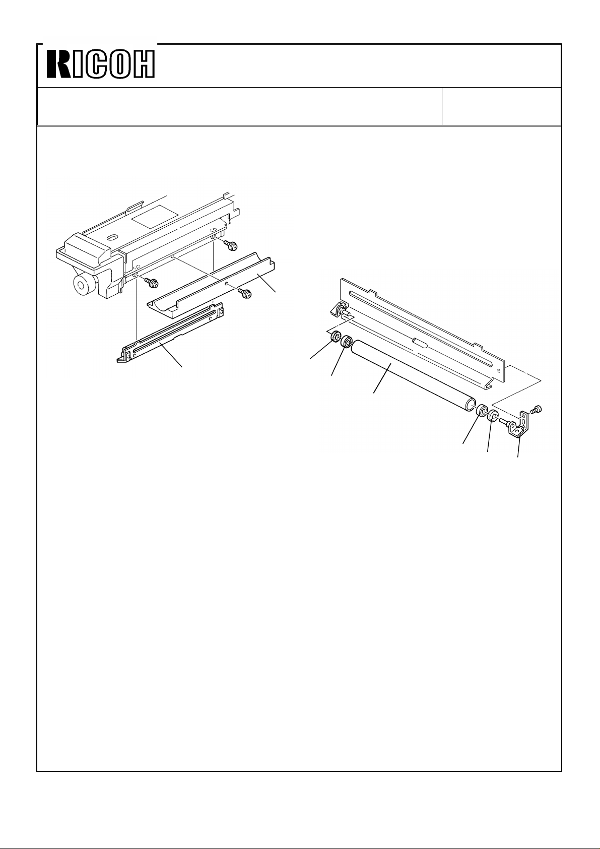
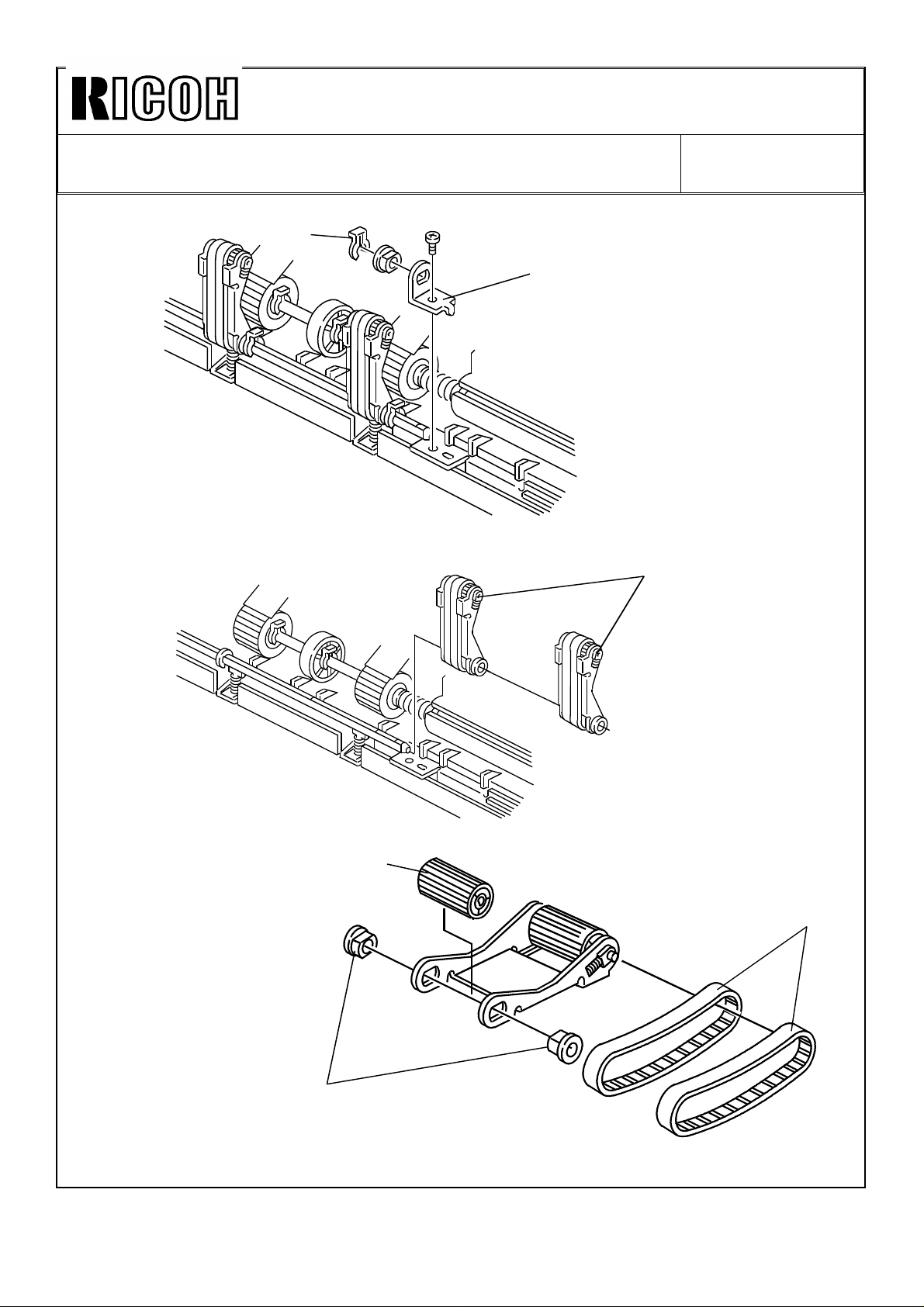
7.10 OIL SUPPLY ROLLER REPLACEMENT
[A]
[E]
[B]
[D]
[C]
1. Pull out the fusing unit.
2. Lower the lever [A].
3. Remove the oil supply unit [B].
4. Remove the spring [C].
5. Remove the bushing [D].
6. Replace the oil supply roller [E].
7. Reassemble the unit.
NOTE: While lowering the lever [A], install the oil supply unit.
Page 6
Technical Bulletin No. RTB-001
SUBJECT: F400/F410 fusing unit modification (Manual corrections) DATE:SEP.15.’93
PAGE: 6 of 6
7.11 CLEANING ROLLER REPLACEMENT
[A]
[B]
1. Pull out the fusing unit.
2. Remove the bottom plate [A] (1 screw).
3. Remove the cleaning roller unit [B] (2 screws).
4. Remove the bracket [C] (1 screw).
5. Remove the cleaning roller [D].
6. Remove the seals [E] and bushings [F] from both sides of the cleaning
roller, then install them to the new cleaning roller.
7. Reassemble the unit.
[E]
[F]
[D]
[F]
[E]
[C]
Page 7
Technical Bulletin No. RTB-002
SUBJECT: F400/F410 transfer belt unit modification
(manual corrections)
PREPARED BY: S.MANO
FROM: Copier Technical Support Group
CHECKED BY:
CLASSIFICATION:
Action Required
Troubleshooting
Retrofit Information
Revision of service manual
Information only
Other
[A]
DATE:SEP.15.’93
PAGE: 1 of 4
MODEL: F400/F410
[B]
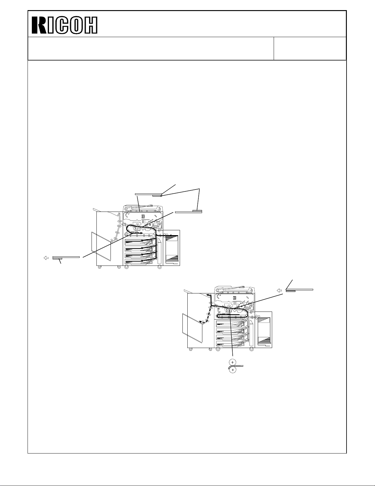
To improve copy quality, the following modification is implemented from the first
mass-production machine.
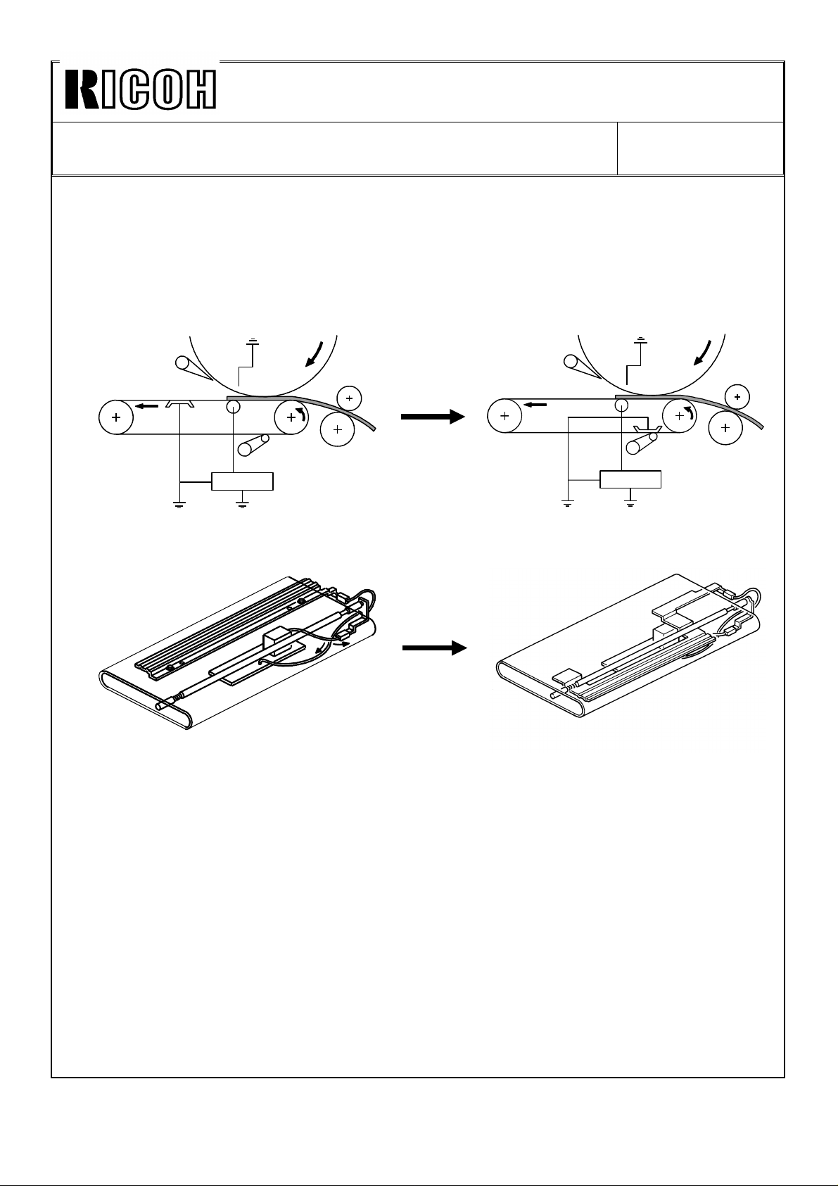
1. The discharge plate position is changed from [A] to [B].
2. The transfer current default data is changed from 40 µA to 50 µA.
Details:
Small gray dots appear under the following conditions:
• Low humidity
• Reverse side of the duplex copy
• Halftone image area
Under the above condition, the paper loses too much of its moisture when it passes the
fusing unit after the first side copy cycle. When the paper is separated from the transfer
belt during second side copying, the remaining electricity on the paper (because of the
high electrical resistance) is suddenly discharged and toner is spread around, creating the
gray dots.
To reduce the occurrence of the above image as much as possible, the position of the
discharge plate is changed and the transfer current is changed.
Page 8
Technical Bulletin No. RTB-002
[B]
SUBJECT: F400/F410 transfer belt unit modification
(manual corrections)
DATE:SEP.15.’93
PAGE: 2 of 4
Manual corrections:
Because of this modification, the following parts of the service manual should be corrected.
Section 2: DETAILED SECTION DESCRIPTIONS
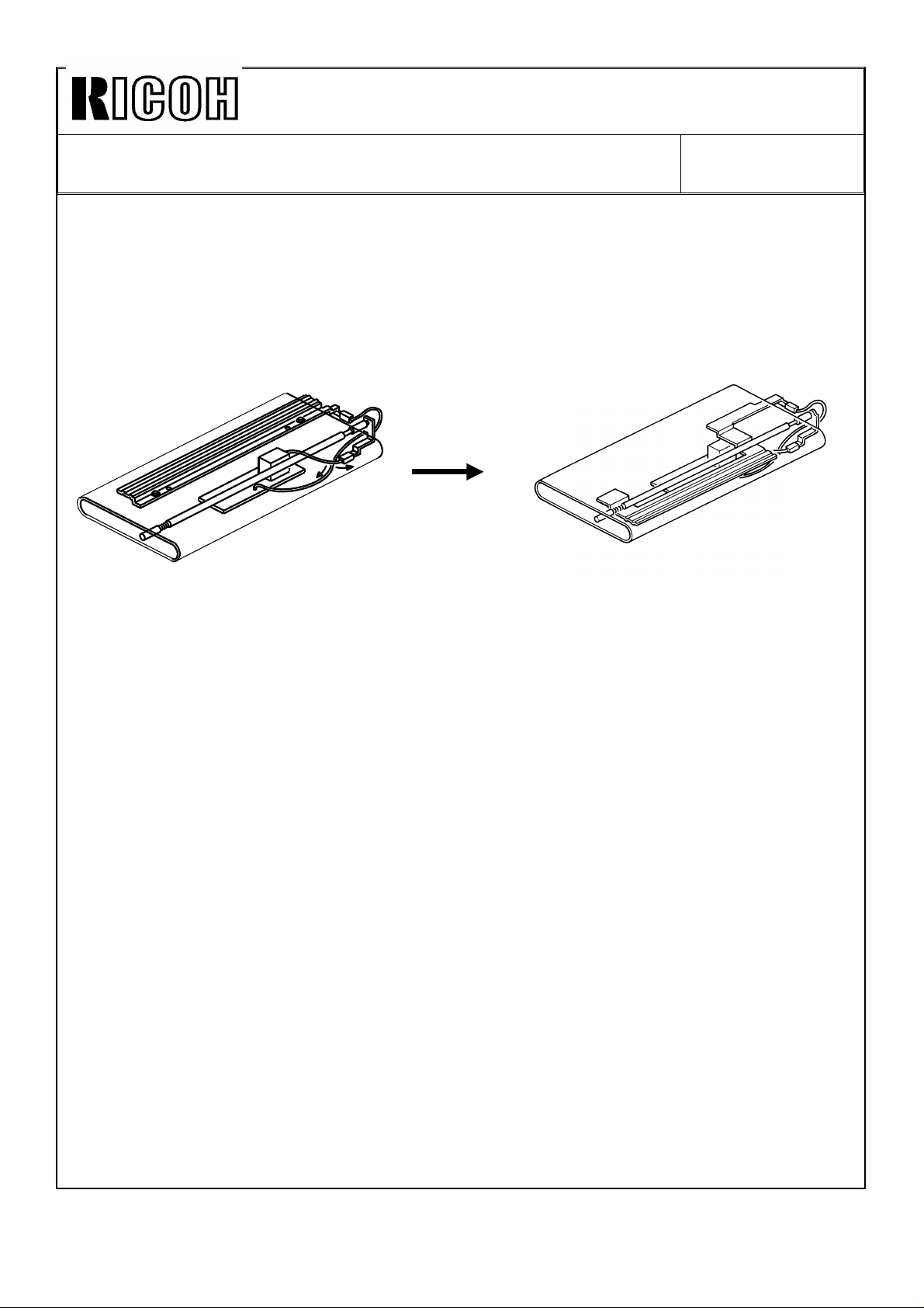
P2-59 Change the discharge plate [F] position as shown in the illustration.
[A]
[E]
[D]
[C]
[F]
Correct the explanation concerning the discharge plate [F] as below:
Incorrect:
Helps paper separation from the transfer belt by discharging the remaining negative
charge on the transfer belt.
Correct:
Discharges the remaining negative charge on the transfer belt and feeds it back to the
transfer power pack to control the transfer current and keep it constant.
Note: Paper is separated from the transfer belt by its stiffness.
Page 9
Technical Bulletin No. RTB-002
SUBJECT: F400/F410 transfer belt unit modification
(manual corrections)
P2-61 Delete "Before separating the paper from the transfer belt," from the first
paragraph. Instead of this, write "After separating the paper from the transfer
belt,"
Also correct the illustrations as below
DATE:SEP.15.’93
PAGE: 3 of 4
Section 4: SERVICE TABLES
P4-13
Default transfer current value is changed from 40µA to 50µA.
Standard data is also changed from 40µA to 50µA.
Page 10
Technical Bulletin No. RTB-002
SUBJECT: F400/F410 Fusing unit modification
(manual corrections)
Section 5: REPLACEMENTS AND ADJUSTMENTS
P5-64 Correct the third (from the top) illustration, the discharge plate position is
changed as shown below.
DATE:SEP.15.’93
PAGE: 4 of 4
Page 11

Technical Bulletin No. RTB-003
SUBJECT: F410 RDH Finisher system duplex method change
(manual corrections)
PREPARED BY: S. MANO
CHECKED BY:
CLASSIFICATION:
Action Required
Troubleshooting
Retrofit Information
For the F410, the alternate paper feed system is disabled.
The following is the new method the F410 uses for copying 1 sided originals to 2 sided
copies.
Please delete pages 14, 15, and 16 of the RDH section and insert the following
explanation.
Revision of service manual
Information only
Other
FROM: Copier Technical Support Group
MODEL: F410
DATE: SEP. 15. ’93
PAGE: 1 of 2
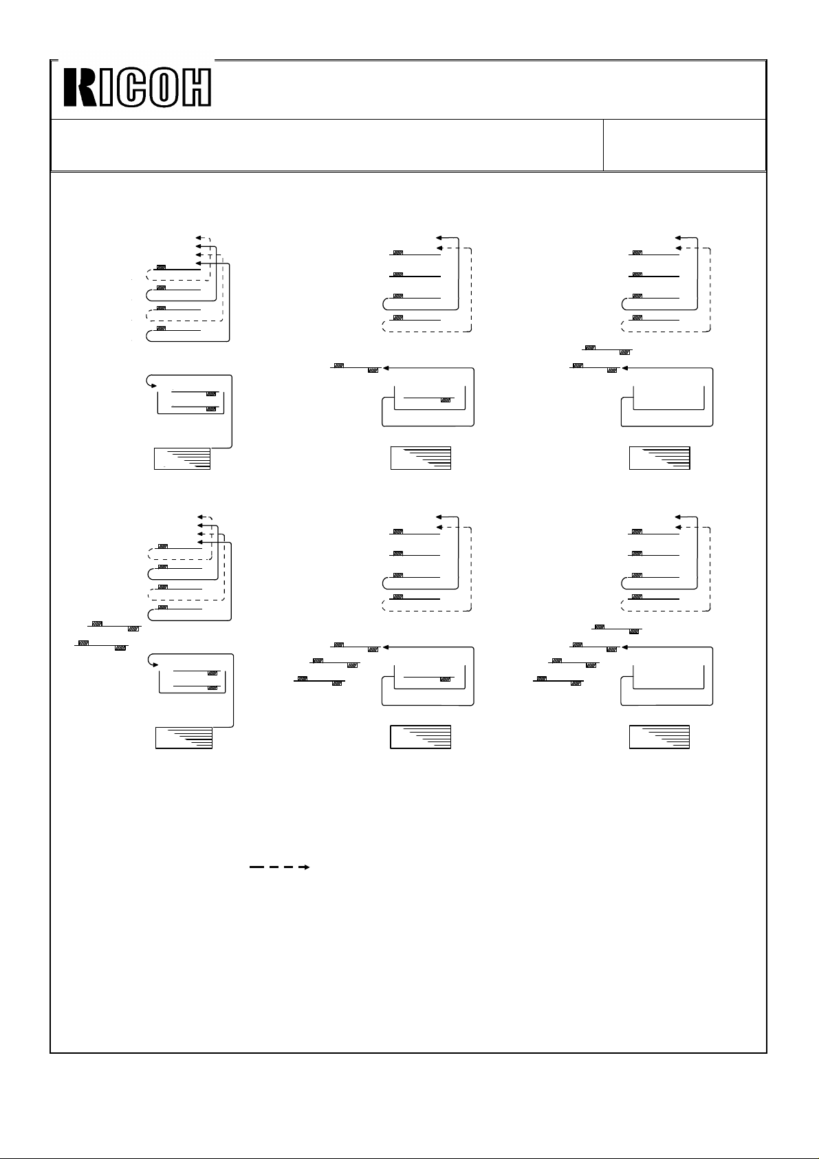
1 SIDED ORIGINAL TO 2 SIDED COPY MODE
When making two-sided copies, first of all, the even pages of the originals placed on the
RDH are copied to the paper from the paper tray. They are stored in the duplex tray. Then
the originals are recirculated, and the odd pages of the originals are copied to the sheets
stored in the duplex tray.
When making two or more sets of copies, the following copy sets are made in the same
way as the first set copy.
Therefore, the original recirculates twice for each copy set.
-Operation- (For example)
Two sets of two-sided copies are made from four one-sided originals.
1) When the start key is pressed, the 4th and 2nd originals are scanned then these
copies are stacked in the duplex tray. The 3rd and 1st originals have only
passed over the exposure glass [Fig. 1].
2) Soon after the 1st recirculation is completed, the second recirculation starts. The
4th originals just passes the exposure glass then the 3rd original is scanned.
This image is copied onto the copy which has been fed from the duplex tray and
is then fed out onto the finisher [Fig. 2].
3) The 2nd original just passes the exposure glass and then the 1st original is
scanned. The copy from the duplex tray is fed for copying the 1st original and
then fed out onto the finisher. At this moment, the duplex tray becomes empty
[Fig. 3].
4) The following steps repeat steps 1) to 3). [Fig. 4] to [Fig. 6].
Page 12
Technical Bulletin No. RTB-003
2 43’
4’3’1’
2’
②
③
SUBJECT: F410 RDH Finisher system duplex method change
(manual corrections)
<RDH>
1
2
3
4
<Duplex>
2
4
<Paper tray>
Fig 1
3’
4’
1’
2’
2’
3’
4
2
Fig 2
❶
①
❷
DATE: SEP. 15. ’93
PAGE: 2 of 2
1’
Fig 3
❸
❹
❸
④
1’
3’
2
4
②
1’
3’
④
❹
❸
④
2
4
②
1’
3’
❸
❶
❷
❶
②
④
2
4
Fig 4 Fig 5 Fig 6
1 2 3 4: 1st recirculated
1’ 2’ 3’ 4’: 2nd recirculated
① ② ③ ④: 3rd recirculated
❶ ❷ ❸ ❹: 4th recirculated
: Without exposing
(for RDH)
Page 13
Technical Bulletin No. RTB-004
SUBJECT: F400/F410 guidance ROMs installation procedure
(manual correction)
PREPARED BY: S.MANO
CHECKED BY:
CLASSIFICATION:
Action Required
Troubleshooting
Retrofit Information
This information is only for Infotec version (A095/A096-26) machines and Ricoh Europe
version (A095/A096-27) machines.
Because it is necessary to install the guidance ROMs at machine installation, to facilitate
the installation procedure, the operation panel is separated from the copier and attached
as an accessory.
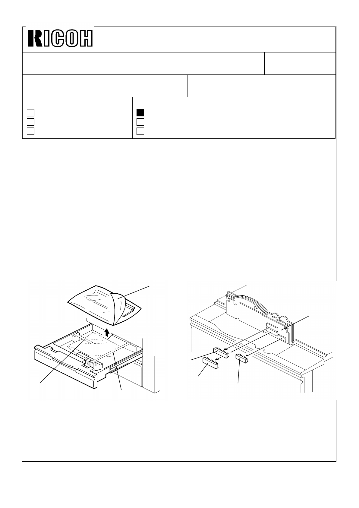
The operation panel, the three fixing screws and the two grounding screws are wrapped in
air packing (cushion) and stored in the second feed tray (universal tray).
Because of this, pages 3-12 and 3-13 of the service manual should be corrected as
follows:
Revision of service manual
Information only
Other
FROM: Copier Technical Support Group
MODEL: F400/F410
DATE:SEP.15.’93
PAGE: 1 of 2
2.3 GUIDANCE ROM, INSTALLATION
[B]
[C]
[A]
[A]
1. Open the 2nd tray then remove the tapes [A] securing the operation panel.
2. Unpack the air packing cushion [B].
3. Install the guidance ROMs (IC111 [C], IC112 [D], IC113 [E]) on the operation panel
board [F].
[E]
[D]
[F]
Page 14
Technical Bulletin No. RTB-004
SUBJECT: F400/F410 guidance ROMs installation procedure
(Manual correction)
[A]
[C]
DATE:SEP.15.’93
PAGE: 2 of 2
[B]
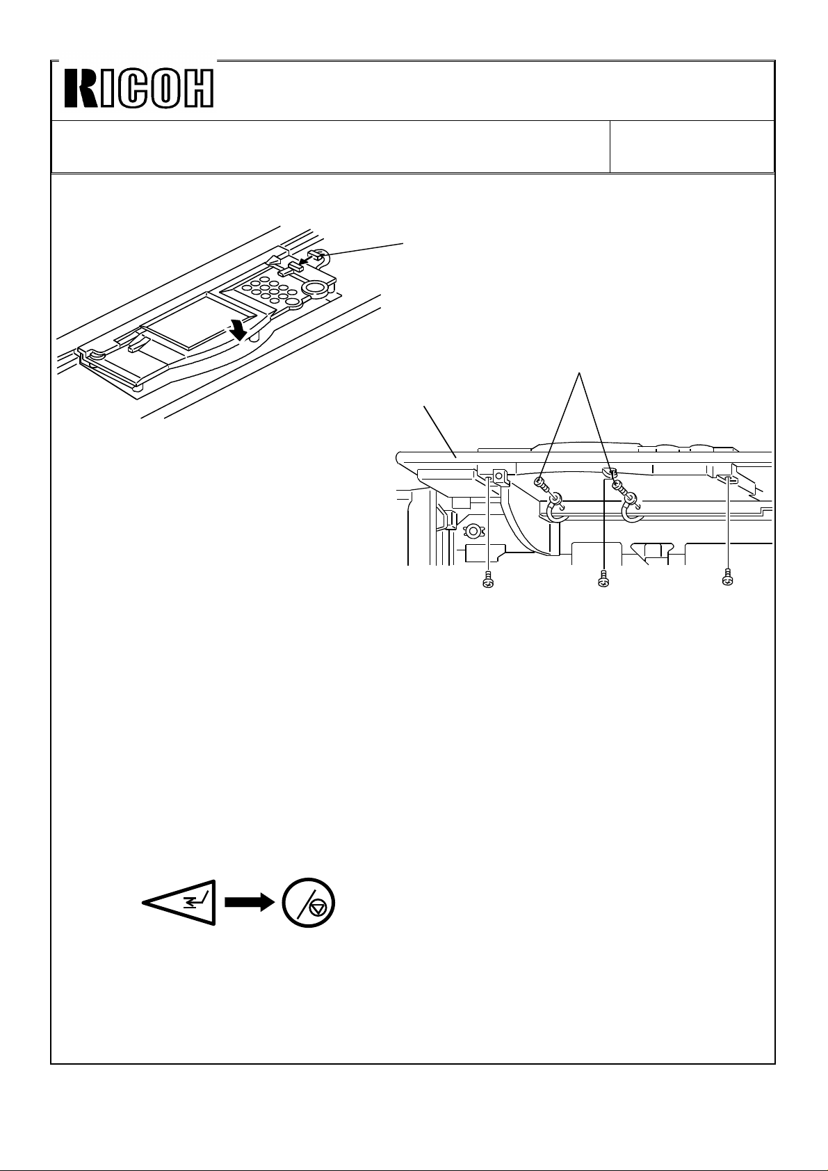
4. Connect the connector [A] to the operation panel.
5. Secure the two protective earth wires with screws [B].
6. Install the operation panel [C] to the copier (3 screws).
7. After installing the new guidance ROMs, plug in the power cord and turn on the main
switch then perform the "touch panel display position adjustment" as follows.
1) Press the interrupt key then press the clear/stop key more than three seconds.
C
2) Follow the guidance on the LCD.
Page 15
Technical Bulletin No. RTB-005
[B]
SUBJECT: F400/F410 Dual Job Feeder separation belts
(manual correction)
PREPARED BY: S.MANO
CHECKED BY:
CLASSIFICATION:
Action Required
Troubleshooting
Retrofit Information
The quantity of the separation belt have been changed from two to four.
Reason of the modification:
On the original printed by the laser printer, the toner may not be fused sufficiently and the
image may smeared by the separation belts.
To prevent this, two more separation belts are added to widen the contacting area
between the separation belts and the original so that the separation pressure is not
concentrated to the narrow area.
Revision of service manual
Information only
Other
FROM: Copier Technical Support Group
MODEL: F400/F410
DATE:SEP.15.’93
PAGE: 1 of 3
After this modification, these separation belts are still PM parts and the replacement
interval is 1PM (120k copies) as same as before this modification.
Because of this modification, the illustrations in page 7, 14, 15, 34 and 35 should be
changed. The quantity of the separation belts should be doubled. There is no correction
except illustrations.
Manual corrections:
Page 7 - upper illustration
[C]
[A]
[E]
[D]
[F]
Page 16
Technical Bulletin No. RTB-005
[B]
[C]
SUBJECT: F400/F410 Dual Job Feeder separation belts
(manual correction)
Page 14 lower illustration
[A]
[D]
[E]
Page 15 illustration
DATE:SEP.15.’93
PAGE: 2 of 3
[B]
[C]
[A]
[D]
Page 17
Technical Bulletin No. RTB-005
SUBJECT: F400/F410 Dual Job Feeder separation belts
(manual correction)
Page 34 lower illustration
[E]
[D]
Page 35 illustrations
DATE:SEP.15.’93
PAGE: 3 of 3
[A]
[B]
[C]
[D]
Page 18

Technical Bulletin No. RTB-006
SUBJECT: F400/F410 Troubleshooting DATE:Nov.30, ’93
PAGE: 1 of 10
PREPARED BY: S.MANO
CHECKED BY:
CLASSIFICATION:
Action Required
Troubleshooting
Retrofit Information
Revision of service manual
Information only
Other
FROM: Copier Technical Support Group
MODEL: F400/F410
TROUBLESHOOTING
The following problems and solutions are based on our experience in the Japanese
market. We think the following countermeasures and customer instructions will help your
service activity in your field.
1. Dark copy/Dirty background
< Phenomenon>
If the machine is moved from a cold place to a warm place and the main switch is turned
on immediately, it is possible that a dark copy appears, or a dirty background copy,
followed by several light copies.
< Possible cause>
If condensation accumulates on the optics or drum because of a sudden temperature
change, less light reaches the drum during the process control data initial setting. The
machine controls for a lighter image density.
If condensation accumulates on the optics, a dark copy appears. If condensation
accumulates on the drum, a dirty background copy appears.
After some time, when the condensation on the optics evaporates or the condensation on
the drum is removed by copy paper going through the copier, the machine will return to
the normal condition and light copies appear.
< Countermeasure>
Wipe off the condensed water on the optics and drum, then perform the process control
data initial setting.
Page 19
Technical Bulletin No. RTB-006
SUBJECT: F400/F410 Troubleshooting DATE:Nov.30, ’93
PAGE: 2 of 10
2. Fusing jam
< Phenomenon>
If there is solid image at the trailing edge on the front side of an original [A] for the front
side copying, this solid image comes to the back side of the leading edge [B] during the
front side copying (front side copying is done after back side copying).
In this case, a fusing jam might occur. (Thinner paper has higher jam possibility.)
< Possible cause>
The solid image at the leading edge on the back side of the paper might stick to the
pressure roller and it will not separate, resulting in a fusing jam.
a. Front
Solid image
Original
b. Rear Side
[A]
Copy
Solid image
[B]
< Countermeasure>
Instruct the customer to select the edge erase mode.
Page 20

Technical Bulletin No. RTB-006
Normal condition
SUBJECT: F400/F410 Troubleshooting DATE:Nov.30, ’93
PAGE: 3 of 10
3. False toner end detection at installation
< Phenomenon>
It is possible that the toner end condition appears on the LCD just after installing a new
machine with a new toner bottle.
< Possible cause>
This is because there is some distance between the toner bottle and the toner supply roller
and it takes time to completely fill the toner hopper with toner. Therefore it is possible for
the toner end condition to occur. In particular, this tends to occur when continuous copies
are made from a high image density original just after installation (developer initial setting).
Start-up
Too much toner is spent
immediately
< Countermeasure>
Make 50 ∼ 100 copies to fully supply the toner into the toner hopper. Stop the copying at
every 10 copies to allow the machine creating the ID sensor pattern to maintain precise
toner density control.
Note: This countermeasure is the same as that for the next item "4. Uneven image
density just after the installation" .
We recommend to perform the above procedure anytime the machine is installed.
Page 21
Technical Bulletin No. RTB-006
SUBJECT: F400/F410 Troubleshooting DATE:Nov.30, ’93
PAGE: 4 of 10
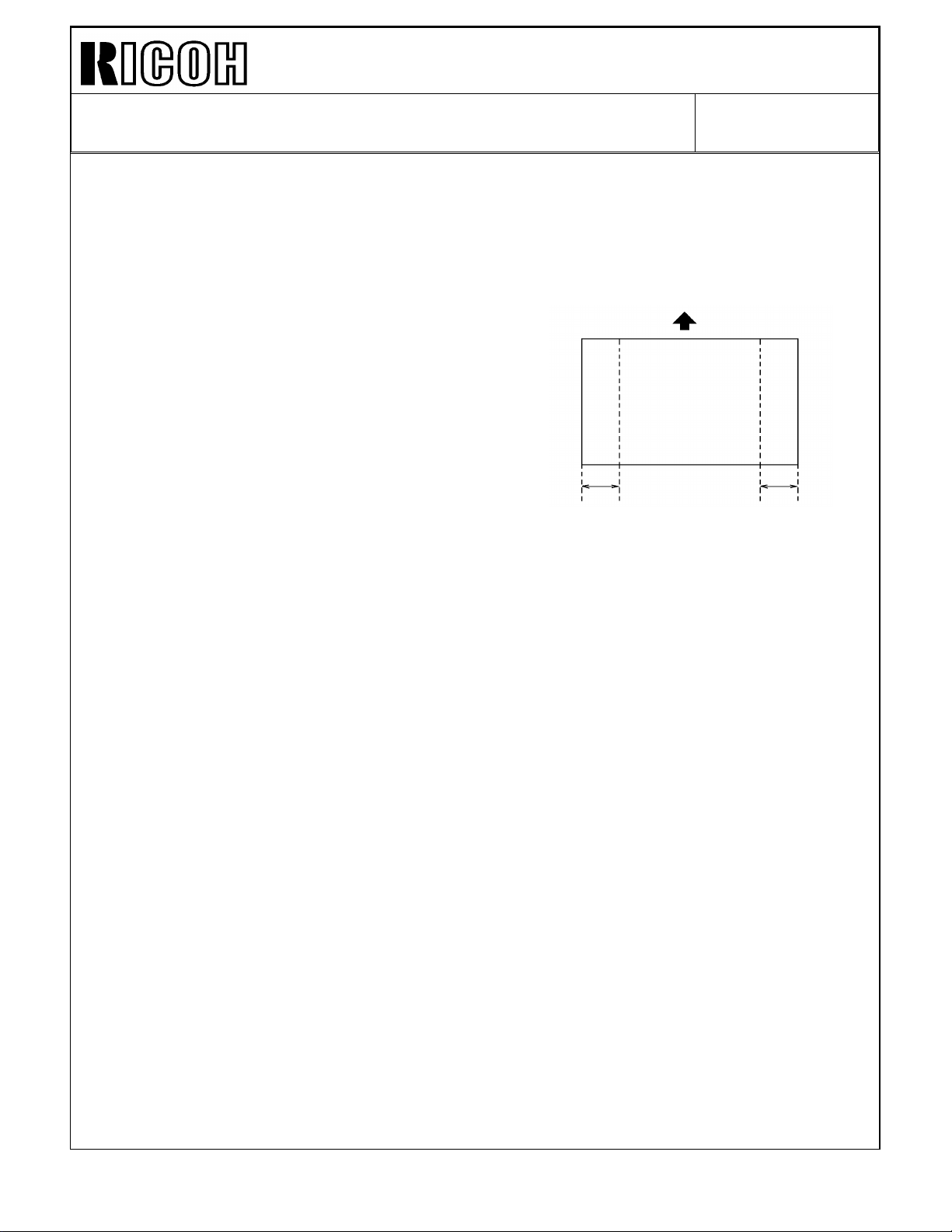
4. Uneven image density just after the installation
< Phenomenon>
Just after installation (up to 50 ∼ 100 copies), the image density (solid image) at the front
and the rear is lighter than the image density at the center.
Lighter Lighter
< Possible cause>
As shown in the illustration in the previous page, in the new toner hopper, the toner is
filled from the front to the rear. It takes time to completely fill the toner hopper. Therefore
it takes about 50 to 100 copies to evenly supply toner to the toner supply roller.
Also, the toner supply roller width is 210mm, which is narrower than wide size paper such
as A4 sideways (297mm) and letter sideways (279mm). Therefore, image density tends to
be lighter especially at the sides.
< Countermeasure>
The countermeasure is the same as that for "3. False toner end detection at
installation"
Make 50 ∼ 100 copies to fully supply the toner into the toner hopper. Stop the copying at
every 10 copies to allow the machine creating the ID sensor pattern to maintain precise
toner density control.
Page 22

Technical Bulletin No. RTB-006
SUBJECT: F400/F410 Troubleshooting DATE:Nov.30, ’93
PAGE: 5 of 10
5.DJF Original jam (F400 only)
When an original generates a lot of static electricity, it tends to stick to the exposure glass
and cause an original jam.
< Countermeasure>
If this occurs, apply a small amount of silicone oil on the exposure glass.
If this problem occurs frequently because of the kind of originals that the customer uses,
install the F410 type exposure glass which has an anti-static coating as a special
countermeasure.
6. Dirty background
< Phenomenon>
If the customer does not turn off the machine at all, a dirty background might appear.
< Possible cause>
The process control data initial setting does not work because it works when the machine
is turned on.
< Countermeasure>
Instruct the customer to turn off the main switch at the end of the day (Turn off the
machine at least 30 minutes; fusing temperature should be lower than 100 degrees ).
Caution: We will modify the software so that the process control data initial setting
functions when the weekly timer turns on the machine. This new software will be
implemented from December production machines. We will let you know the details,
such as cut-in serial number, in a later RTB.
Page 23

Technical Bulletin No. RTB-006
SUBJECT: F400/F410 Troubleshooting DATE:Nov.30, ’93
PAGE: 6 of 10
7. Distorted vertical lines
< Phenomenon>
Vertical lines are sometimes distorted because the original is wavy and is not completely
pressed against the exposure glass by the platen cover or DJF/RDH.
Note: This is the same situation as previous models (F30 series, F40)
< Countermeasure>
Instruct the customer to press the original against the exposure glass by using a weight,
such as a paper package.
8. Sorter stapler installation environment
< Phenomenon>
When direct sunlight strikes the bin jam sensor (a photo transistor), it causes a sensor
malfunction, and the machine does not staple even if staple mode is selected.
< Countermeasure>
1) Avoid installing the machine under direct sunlight
2) Install a piece of mylar around the bin-jam sensor (photo-transistor) to protect from
direct sunlight.
Page 24
Technical Bulletin No. RTB-006
SUBJECT: F400/F410 Troubleshooting DATE:Nov.30, ’93
PAGE: 7 of 10
9. DJF Original Skew
< Phenomenon>
If original skews occur as illustrated even if the DJF height is correctly adjusted, perform
the following adjustment.
Rear
Left scale
< Possible cause>
This skew is caused because the transport belt is faster than the feed-in motor speed,
even if both motor speeds are within the specification.
< Countermeasure>
1. Feed-in motor speed adjustment
Adjust the feed-in motor speed so that the motor speed becomes higher (within
specification).
1–1 Turn DIP SW 101-1, 2, 4 to "ON".
1–2 Turn DIP SW 102-1 to "ON".
1–3 Turn VR 103 towards "H" to turn LED 101 (Red) on.
1–4 Turn VR 103 towards "L" to turn LED 102 (Green) on.
2. Transport belt motor speed adjustment
Adjust the transport belt motor speed so that the motor speed becomes lower (within
specification).
1–1 Turn DIP SW 101-1, 2, 4 to "ON".
1–2 Turn DIP SW 102-2 to "ON".
1–3 Turn VR 104 towards "L" to turn LED 103 (Red) on.
1–4 Turn VR 104 towards "H" to turn LED 102 (Green) on.
Page 25

Technical Bulletin No. RTB-006
No good
SUBJECT: F400/F410 Troubleshooting DATE:Nov.30, ’93
PAGE: 8 of 10
10. Sorter Stapler Entrance jam
< Phenomenon>
If the mylar is set incorrectly, paper jams frequently occur around the sorter stapler
entrance.
Good
< Countermeasure>
Set the mylar in the correct position without buckling, curling or waving.
Page 26

Technical Bulletin No. RTB-006
No good
SUBJECT: F400/F410 Troubleshooting DATE:Nov.30, ’93
PAGE: 9 of 10
11. Abnormal LCD panel indication
< Phenomenon>
The copy counter indicates "8" even if another key (for example, the clear modes key) is
pressed. For instance, if the clear modes key is touched three times, the copy counter
indicates 888.
< Possible cause>
The grounding wire terminal is touching the operation panel board circuit pattern.
When the operation panel is opened while the grounding screws are left secured to the
machine frame, if the grounding wire is pulled strongly (this is especially possible when the
guidance ROM is pushed in the socket) the terminal may be rotated and bent. If the bent
terminal is pressed against the insulating sheet, it cuts part of insulating sheet and touches
the legs of electrical elements behind the insulating sheet, resulting in a short-circuit.
Good
< Countermeasure>
Correct the bent terminal and repair the insulating sheet with insulating tape such as teflon
tape.
Especially, be careful when you install the guidance ROMs at installation.
Page 27

Technical Bulletin No. RTB-006
SUBJECT: F400/F410 Troubleshooting DATE:Nov.30, ’93
PAGE: 10 of 10
12. PCBs or Power packs damage
< Possible causes>
When units such as drum unit or transfer belt unit are removed while the main switch is
turned on, electrical noise or surge current might occur, resulting in PCB damage.
< Countermeasure>
Replace the damaged PCB or power pack.
CAUTION: Turn off the main switch before disconnecting the connector
or removing the unit.
13. SC548 (Additional information for page 6-17 in the service manual)
< Countermeasure>
If this occurs, before replacing the optics PCB and main control board, check the
connection between the main harness and the relay harness (drawer connector terminals)
and the connection between the relay harness and the thermistor (2P connector).
Page 28
Technical Bulletin No. RTB-007
SUBJECT: SC502, 508, 510, 511 DATE:Nov.30, ’93
PAGE: 1 of 3
PREPARED BY: S.MANO
CHECKED BY:
CLASSIFICATION:
Action Required
Troubleshooting
Retrofit Information
< Phenomenon >
SC502, 508, 510, 511
< Possible causes >
When the tandem tray is closed roughly, it bounces slightly to the front. This breaks the
connection of the drawer connectors at the right or left tandem tray.
< Countermeasure >
1. Field countermeasure
Revision of service manual
Information only
Other
FROM: Copier Technical Support Group
MODEL: F400/F410
Instruct the customer to gently push in the tandem tray until it stops.
Also instruct the customer to do the following operation if the problem occur:
After drawing-out then pushing in the tandem tray, turn the main switch off and on.
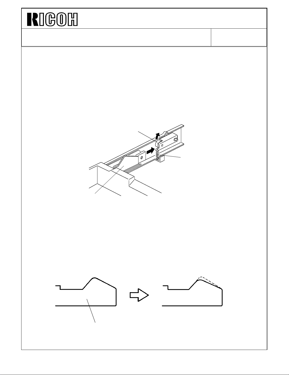
Apply grease (silicone grease G-501) to the following points (see the illustrations in the
following pages). This reduces the friction between the tandem tray and the guide rail to
make the drawing operation of the tandem tray smoother. This helps the lock lever to
position the tandem tray at the correct position. In other word, if the tandem tray bounces
slightly to the front, the lock lever pushes the lock plate to move the tray back to the
correct position.
Page 29

Technical Bulletin No. RTB-007
SUBJECT: SC502, 508, 510, 511 DATE:Nov.30, ’93
PAGE: 2 of 3
Point # 2
Point # 1
Lock Lever
Lock Plate
Point # 1 : The upper edge of the lock plate
Point # 2 : The surface of the lock lever roller where touching the lock plate
Point # 3
Point #4
Point #5
Point # 3 : Positioning Pin
Point # 4 & # 5 : Guide Rails
Page 30
Technical Bulletin No. RTB-007
SUBJECT: SC502, 508, 510, 511 DATE:Nov.30, ’93
PAGE: 3 of 3
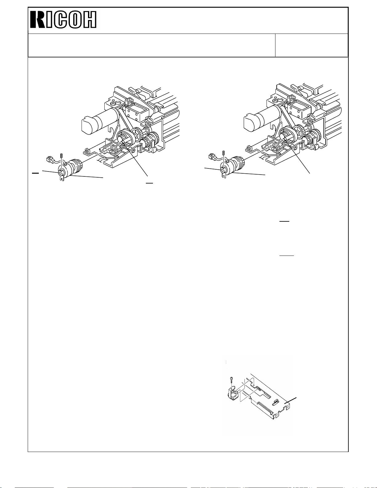
2. Production machine countermeasure
To improve the accuracy of the tandem tray lock position, the following improvement will
be implemented in the mass-production machines. (Please refer to Modification Bulletin for
cut-in serial numbers. An MB will be issued as soon as the modification is implemented.)
1. Grease is applied at the factory as described in the previous page.
2. Also to make the tray movement smoother, the roller [A] on the lock lever is changed
from a resin roller to metal roller with ball bearings.
[A]
[B]
[C]
3. The spring [B] tension applied to the tray lock lever is increased from 1.5kgf to 3.0kgf
(spring is changed).
Because the spring tension is increased, to keep the tandem tray drawing force constant,
the lock plate [C] shape is flatter.
[C]
Page 31

Technical Bulletin No. RTB-008
SUBJECT: DJF Multiple feeding DATE:Nov.30, ’93
PAGE: 1 of 2
PREPARED BY: S. MANO
CHECKED BY:
CLASSIFICATION:
Action Required
Troubleshooting
Retrofit Information
< Phenomenon >
Original multiple feeding occurs when there is high friction between the originals. This
tends to occur especially when the originals have staple holes, or computer forms with
rough edg es.
< Possible cause >
[C]
Revision of service manual
Information only
Other
FROM: Copier Technical Support Group
MODEL: F400/F410
[D]
[A]
[B]
When the originals [A] comes between the feed rollers [B] and the separation belts [C],
they meet the mylar [D] between them and the separation belts. This guide mylar
transports the originals smoothly to the gap between the feed rollers and the separation
belts. The mylar length determines the original separation force. If the mylar is longer, the
area where the originals touch the separation belt becomes narrower, therefore the
separation force become weaker. If the mylar is shorter, the separation force becomes
stronger. (If it is too short, too much separation force stops original feed)
As a result of our investigation, we found that making the mylar 2mm shorter is the best
condition (higher separation ability without feeding error).
Page 32

Technical Bulletin No. RTB-008
SUBJECT: DJF Multiple feeding DATE:Nov.30, ’93
PAGE: 2 of 2
< Countermeasure >
Replace the original guide mylars (2 mylars per machine). New part is the assembled part
of the mylar and the bracket. New part number is A3761254.
For the cut-in serial number, please refer to the modification bulletin which will be issued
soon.
Guide mylar ass’y : Part number A3761254
Page 33

Technical Bulletin No. RTB-009
SUBJECT: Installation procedure DATE:Nov.30, ’93
PAGE: 1 of 3
PREPARED BY: S.MANO
CHECKED BY:
CLASSIFICATION:
Action Required
Troubleshooting
Retrofit Information
1. Additional shipping tape on the fusing exit unit. (F400/F410 service manual - installation
procedur e, page 3-6 )
From the first mass-production machine, a retaining tape [A] is added to prevent the fusing
exit guide from opening during a transportation. Please be sure to remove the tape at
installation.
Revision of service manual
Information only
Other
FROM: Copier Technical Support Group
MODEL: F400/F410
DJF
LCT
[A]
2. USA 20A plug socket
The shape of the socket for 20A [B] differs from that for 15A [C]. The two are not
interchangeable. If there is no 20 A socket at the customer location, the electrical line
must be changed as well as the socket. Contact the local electric company for more
information.
[B] [C]
Page 34

Technical Bulletin No. RTB-009
SUBJECT: Installation procedure DATE:Nov.30, ’93
PAGE: 2 of 3
3. Caution for DJF shipping tape removal (dual job feeder service manual - installation
procedure page, 24)
When removing the tape [B] fixing the original press roller shaft [C], be careful to confirm
that the shaft is correctly in the holder [D]. It is possible that the shipping tape adheres
strongly to the shaft. The shaft migit be pulled out from the holder when the tape is
removed.
If the shaft is out of position, the original will not feed.
[B]
[C]
[D]
Page 35

Technical Bulletin No. RTB-009
[A]
SUBJECT: Installation procedure DATE:Nov.30, ’93
PAGE: 3 of 3
4. Caution when installing the LCT (large capacity tray service manual - installation
procedure, page 12)
When installing the tray unit [A] to the LCT connector [B], be careful not to pinch the
harness between the feed unit bracket [C] and the tray unit bracket [D], as shown.
[D]
[C]
[B]
To prevent this, fix the harness with a tape as shown before installing the tray unit.
Tape
Page 36

Technical Bulletin No. RTB-010
SUBJECT: DJF feed roller assembly replacement DATE:Nov.30, ’93
PAGE: 1 of 3
PREPARED BY: S.MANO
CHECKED BY:
CLASSIFICATION:
Action Required
Troubleshooting
Retrofit Information
1. Manual correction
In the feed roller replacement procedure (page 32 to 33), there are steps asking to remove
the original table and original guide. Actually, this procedure is not necessary. Please skip
steps 2, 3, 4, and 5. You can directly access the feed roller.
2. Procedure change due to modification.
In the domestic market, we have experienced that the customer took off the feed roller
assembly [A] when removing a jammed original. When the jammed original is pulled to the
front, the feed rollers are pulled to the front and the joint part [B] comes out from the drive
shaft. To prevent this, The middle roller [C] position has been changed (to the rear) as
shown below.
Revision of service manual
Information only
Other
[C]
FROM: Copier Technical Support Group
MODEL: F400/F410
[B]
Front
[A]
Guide Plate
[B]
Old
[C]
New
Page 37

Technical Bulletin No. RTB-010
SUBJECT: DJF feed roller assembly replacement DATE:Nov.30, ’93
PAGE: 2 of 3
Before the modification, the middle roller could be shifted to the front when the feed roller
was pulled to the front. After the modification, when the feed roller is pulled to the front,
the middle roller hits the guide plate and it cannot be moved to the front. This prevents the
joint part from being separated by mistake.
To replace the feed roller assembly, the following procedure is necessary before
performing step 6 (slide the feed roller assembly to the front, then remove it).
* Remove the guide mylars
* Remove the snap ring.
* Hold the feed roller.
After the modification, procedure "14.2 feed roller replacement" is changed as shown in
next page.
Page 38

Technical Bulletin No. RTB-010
SUBJECT: DJF feed roller assembly replacement DATE:Nov.30, ’93
PAGE: 3 of 3
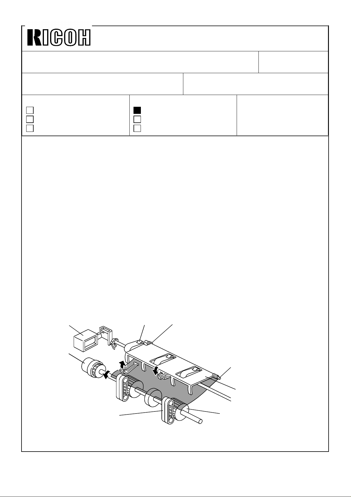
[B]
[A]
Rear
[E]
[F]
[C]
1. Turn off the main switch then open the feed cover [A].
2. Remove the guide mylars [B] ( 1 screw each ).
3. Remove the snap ring [C].
4. Slide the roller [D] to the rear.
[D]
Front
5. Hold the feed roller [E] then slide the shaft to the front, then remove the feed roller
assembly as shown.
6. Remove the four snap rings [F], then remove the feed rollers.
7. Install the new feed rollers, then re-assemble the machine.
Page 39

Technical Bulletin No.RTB-011
SUBJECT: Software modification DATE:Dec.15, ’93
PAGE: 1 of 5
PREPARED BY: S. MANO
CHECKED BY:
CLASSIFICATION:
Action Required
Troubleshooting
Retrofit Information
We learned of the following problems and have modified the software (ROMs on the main
control board) to solve them.
IC NUMBER OLD PART NUMBER NEW PART NUMBER
IC120 (4M Bite)
IC133 (1M Bite)
Revision of service manual
Information only
Other
A0965121K
A0965123K
FROM: Copier Technical Support Group
MODEL: F400/F410
A0965151
A0965153
1. Registration Jam for perforated paper (4 holes)
Continuous paper runs produce jams when perforated paper is fed in. This occur when the
holes match the location of the registration sensor.
At the paper leading edge, the registration sensor goes from OFF to ON. Just after the
registration sensor turns on, the chattering check is done. When the hole at the leading
edge of the paper passes above the registration sensor, the sensor output fluctuates,
resulting in a paper jam.
2. Process control data initial setting does not functions when the
machine is turned on by the weekly timer.
Process control data initial setting does not function when the machine is turned on by the
weekly timer. For customers who never turn off the main switch, the auto process control
does not work and after about 150k or more copies, maybe resulting in darker copies
followed by dirty backgrounds.
3. ADS does not functions with RDH last original
Only for the copy image of the last original fed by the RDH, the auto image density
selection does not function. Instead, the 4th ID level is selected.
If multiple sets of copies are made, this appears only for the last copy of the first set.
Page 40

Technical Bulletin No.RTB-011
SUBJECT: Software modification DATE:Dec.15, ’93
PAGE: 2 of 5
4. SC742
This occurs only for the RDH and Finisher system.
When the following conditions are met, the positioning roller [A] interrupts the paper feed
out pawl [B], resulting in an SC742 condition.
• The previous customer selected the staple mode and this mode is not
cleared. (The staple mode remains selected).
• Only one original to be copied.
• More than three copies are mode. (The problem occurs after feed-
ing 4 or more copies).
Note: After the modification, when the above conditions are met, the interval between the
copies becomes longer to prevent the interruption between the positioning roller [A]
and the paper feed out pawl [B]. Only in this case, the CPU reduces from 55CPM
to 22.5CPM (A4/Letter sideways).
If the above three conditions are not met, the copy speed is 55CPM.
[A]
[B]
[A]
Page 41

Technical Bulletin No.RTB-011
SUBJECT: Software modification DATE:Dec.15, ’93
PAGE: 3 of 5
5. Two roller marks on halftone image areas
When the following conditions are met, lighter lines appear at the latter half of the image.
• Last paper fed from the duplex tray.
• There is halftone image area at the latter half of the front side copy.
A3
This is caused by the duplex transport clutch turning off when the paper is still being
transported by the duplex transport rollers [A]. Under this condition, the leading edge of
the paper is transported by the vertical transport rollers [B], so the paper is rubbed by the
duplex transport rollers [A].
Especially for halftone images, there is little toner on the paper, and the toner particles are
not bound to each other. Therefore, half tone images are easier to smear than solid or line
images, resulting in lighter lines appearing.
[B]
[A]
Page 42

Technical Bulletin No.RTB-011
[A]
SUBJECT: Software modification DATE:Dec.15, ’93
PAGE: 4 of 5
6. Modes clear when the key counter is disconnected
When the key counter is disconnected from the copier, normally, the selected modes are
automatically cleared (mode clear function). At the field’s request, we have enabled
holding of the previous mode even after the key counter is disconnected. The default
setting is still the same as before (mode clear function).
When the customer connects the key card to the key counter connector, if this new mode
is selected, the input modes are still held even when the card’s credit is expired.
• How to access this mode
1. Enter SP adjustment mode.
2. Touch the "Prev." key (access page 16 - extra page).
3. Touch the "Set" key [A] of the 4th item.
4. Input "1".
5. Press the enter key of the numeral keys.
00000
00001
Page 43

Technical Bulletin No.RTB-011
SUBJECT: Software modification DATE:Dec.15, ’93
PAGE: 5 of 5
The cut-in serial number is as follows.
Japan production : From December ’93 Production
Code Serial number
A095 - 10 -----------A095 - 15 -----------A095 - 17 -----------A095 - 22
A095 - 26
A095 - 27
A095 - 29
A096 - 10 -----------A096 - 15 -----------A096 - 17 -----------A096 - 22
A096 - 26
A096 - 27
A096 - 29
5233120001 ∼
3D51230001 ∼
A3353120001 ∼
A335312XXXX ∼
52731200 01 ∼
3D61230001 ∼
A3363120001 ∼
A336312XXXX ∼
REI Production : From 1st Production
Code Serial number
A095 - 10
A095 - 15
A095 - 17
A096 - 10
A096 - 15
A096 - 17
5203520001 ∼
2635100001 ∼
A3353520001 ∼
5243520001 ∼
28351000 01 ∼
A3363520001 ∼
Page 44

Technical Bulletin No. RTB-012
SUBJECT: Electrical malfunctions due to improper grounding DATE:Jan. 31, ’93
PAGE: 1 of 6
PREPARED BY: S. Mano
CHECKED BY:
CLASSIFICATION:
Action Required
Troubleshooting
Retrofit Information
If grounding is incomplete (the detailed locations are explained in the following pages),
electrical noise (created by the static charge arching) affects the 5V line. In this case, it is
possible that the following electrical malfunction may occur. Especially under low humidity
conditions, the malfunction occurrence will be higher due to higher static electricity
generation. When assembling the machine during servicing, be sure that the grounding is
complate.
Revision of service manual
Information only
Other
FROM: Copier Technical Support Section
MODEL:
F400/F410
Typical phenomenon
1. Scanner overruns the home position and hits the optic frame.
2. Exposure lamp turns off suddenly and the scanner stops during copying, causing the
copy paper to stop in the fusing unit. On the copy paper, a partially black solid image
will appear because the exposure lamp turns off during the copy process.
3. When the the paper is removed from the fusing unit after above mentioned (item #2)
paper jam occurs, the selected copy modes are cleared.
4. Erase lamp turns on at the wrong timing and wrong position. Therefore, the copy
image becomes partially void.
Page 45

Technical Bulletin No. RTB-012
SUBJECT: Electrical malfunctions due to improper grounding DATE:Jan. 31, ’93
PAGE: 2 of 6
POSSIBLE CAUSES
If the following grounding connection is incomplete, the electrical malfunctions may occur.
1. By-pass size sensor bracket
If the grounding wire [A] is not fixed to the by-pass paper size sensor [B] (variable resistor)
correctly, the paper tends to generate high static charge (especially when using the tracing
paper). The static electricity on the paper may leak to the by-pass size sensor bracket.
[A]
[B]
2. Development unit grounding spring
If the grounding spring [C] at the rear side of the development unit does not properly
contact the grounding plate [D], excessive static charge generated by the developer may
arc from the development unit to the registration guide plate.
From the December 1993 first production machines, the grounding spring inner diameter
has been reduced so that it is properly secured and positioned by the stepped screw.
[D]
[C]
Page 46

Technical Bulletin No. RTB-012
SUBJECT: Electrical malfunctions due to improper grounding DATE:Jan. 31, ’93
PAGE: 3 of 6
3. Development unit grounding spring plate
If the grounding spring plate [A] on the development unit guide rail contacts the
development unit incorrectly, the excessive static charge generated by the developer may
arc to the development unit guide rail.
[A]
4. ID sensor board bracket
If the grounding wire [B] is not fixed to the ID sensor board bracket correctly, when copy
paper with a high static charge touches the ID sensor board bracket, the static electricity
on the paper may arc to the ID sensor board bracket.
[B]
Page 47

Technical Bulletin No. RTB-012
SUBJECT: Electrical malfunctions due to improper grounding DATE:Jan. 31, ’93
PAGE: 4 of 6
5. Pick-off pawl shaft
When copy paper with a high static charge touches the pick-off pawl shaft [A], the static
electricity on the paper arcs to the pick- off pawl shaft.
To prevent this malfunction, the pick-off pawl tension spring [B] is electrically connected to
the ID sensor board bracket. This modification was implemented from the December 1993
first production machines.
[A]
[C]
[B]
Spring replacement procedure
1) Remove the ID sensor bracket [C] (2 screws).
2) Remove the old tension spring (1 E-ring).
3) Install the new tension spring (1 E-ring).
4) Re-install the ID sensor board bracket. Secure the hook [D] at the end of the spring
to the screw fixing the ID sensor board bracket.
[D]
Page 48

Technical Bulletin No. RTB-012
SUBJECT: Electrical malfunctions due to improper grounding DATE:Jan. 31, ’93
PAGE: 5 of 6
6. Main charge corona unit
If the main charge corona is not set correctly, poor electrical contact at the rear terminal
may result in high voltage line leakage. Be sure to secure the fixing screw and secure the
main charge corona unit to the drum stay with a screw.
7. Fusing roller anti-static brush
If the anti-static brush [A] does not touch the edge of the fusing roller, its possible for static
electricity to accumulate on the fusing roller. It may arc to nearby metal parts.
[A]
8. Drum shaft grounding terminal
If the drum shaft grounding terminal [B] is not set (does not contact the drum shaft)
correctly or it has too much wear (this part should be replaced at every 360k copies),
incomplete grounding may occur resulting in electrical malfunction.
[B]
Page 49

Technical Bulletin No. RTB-012
SUBJECT: Electrical malfunctions due to improper grounding DATE:Jan. 31, ’93
PAGE: 6 of 6
9. Cleaning brush roller grounding wire
If the grounding wire is not installed correctly, static charge on the cleaning brush may arc
to nearby metal parts resulting in electrical malfunction.
[A]
Concerning item 2 (Development unit grounding spring) and item 5 (Pick-off pawl shaft),
the countermeasure parts will improve the grounding condition, part number of the
countermeasure parts kit is A0969900.
Page 50

Technical Bulletin No. RTB-013
SUBJECT: SORTER STAPLER (A377) ENTRANCE GUIDE DATE:Jan. 31, ’93
PAGE: 1 of 6
PREPARED BY: S. MANO
CHECKED BY:
CLASSIFICATION:
Action Required
Troubleshooting
Retrofit Information
It has been reported that several sorter stapler (A377) entrance guides became deformed.
This occurs when the sorter stapler (A377) is taken out of the carton or during
transportation.
Because the entrance guide plate sticks out from the machine, it is held and bend by the
transportor or it is hit during transportation.
To prevent the deformation of the sorter stapler entrance guide plate, the entrance guide
plate [A] is separated from the sorter stapler and attached on the front door.
This is implemented from the first February 1994 production machines.
Whenever transporting the sorter stapler after taking out of the carton box, separate the
guide plate from the sorter stapler. Reset it just before you dock the sorter stapler to the
copier.
Revision of service manual
Information only
Other
FROM: Copier Technical Support Section
MODEL:
F400/F4 10
SORTER STAPLER
(A377)
The installation procedure (accessory) is modified too. Please refer to the following pages.
Step #11 has been adde d. The othe r steps ar e the same as before.
[A]
Page 51

Technical Bulletin No. RTB-013
SUBJECT: SORTER STAPLER (A377) ENTRANCE GUIDE DATE:Jan. 31, ’93
PAGE: 2 of 6
INSTALLATION PROCEDURE
[B]
[A]
[B]
[A]
[B]
[A]
[B]
[A]
[A]
[E]
[C]
CAUTION: Unplug the copier power cord before starting the following
procedure.
[D]
1. Remove the strips of tape [A] and the cushions [B].
2. Open the front door and remove the inner cover [C] (3 screws).
3. Remove a strip of tape [D] securing the gripper unit and remove a
cushion [E]. Then re-install the inner cover [C].
Page 52

Technical Bulletin No. RTB-013
[C]
SUBJECT: SORTER STAPLER (A377) ENTRANCE GUIDE DATE:Jan. 31, ’93
PAGE: 3 of 6
[A]
[A]
[D]
[B]
[E]
4. Remove five plastic caps [A] on the copier’s left cover.
5. Install the front connecting bracket [B] (2 screws - M4 x 12) and the rear connecting
bracket [C] (2 screws - M4 x 12) on the copier.
6. Stick the entrance guide mylar [D] on the copier exit area as shown.
NOTE: Align the edge [E] of the cover and mylar.
Page 53

Technical Bulletin No. RTB-013
SUBJECT: SORTER STAPLER (A377) ENTRANCE GUIDE DATE:Jan. 31, ’93
PAGE: 4 of 6
[C]
[D]
[H]
[A]
[B]
[G]
[E]
[F]
7. Secure the protective earth wire [A]* (1 screw with spring washer) and the wire [B] (1
screw with spring washer).
NOTE*: For all models other than those intended for North America, the green wire is
intended as a functional ground and should be connected as shown.
8. Connect the 4P connector [C] and the fiber optic connector [D].
9. Open the front door of the sorter stapler and remove the screw [E] fixing the locking
lever [F], then lower the locking lever.
10. Stick the cushion [G] on the proof tray.
11. Install the entrance guide plate [H] (2 screws -M4 x 6) which is in the bag on the front
door.
12. Align and press the sorter stapler against the copier and fix them by raising the locking
lever [F].
[H]
Page 54

Technical Bulletin No. RTB-013
SUBJECT: SORTER STAPLER (A377) ENTRANCE GUIDE DATE:Jan. 31, ’93
PAGE: 5 of 6
[B]
[A]
[C]
13. Secure the locking lever [A] (1 screw).
14. Install the proof tray [B].
15. If the gap between the top of the sorter stapler and the copier is too great, adjust by
placing caster stoppers [C].
[C]
Page 55

Technical Bulletin No. RTB-013
SUBJECT: SORTER STAPLER (A377) ENTRANCE GUIDE DATE:Jan. 31, ’93
PAGE: 6 of 6
[A]
16. Remove the green plastic clip [A] from the staple cartridge, and install the cartridge in
the stapler.
NOTE: When installing the staple cartridge, make sure that all the staple sheets [B]
are in the initial position.
[B]
17. Plug in the copier.
18. Turn on the main switch of the copier and test the operation of the sorter stapler.
NOTE: The copier automatically recognizes that the sorter stapler has been installed.
The stapler will not staple for the first 10 or so copies until the first staple
moves to the proper position from the cartridge.
Page 56

Technical Bulletin No. RTB-014
SUBJECT: FINISHER ENTRANCE GUIDE DATE:Jan. 31, ’93
PAGE: 1 of 6
PREPARED BY: S. MANO
CHECKED BY:
CLASSIFICATION:
Action Required
Troubleshooting
Retrofit Information
It has been reported that several sorter stapler (A377) entrance guide become deformed.
(This is introduced in F400/F410 RTB No.13, please refer to it for details)
Since the F400 finisher has the same type of guide plate, the entrance guide plate [A] is
separated from the finisher and kept in the accessory bag.
This is implemented from the first February 1994 production machine.
Whenever transporting the sorter stapler after taking out of the carton box, separate the
guide plate from the finisher. Reset it just before you dock the finisher to the copier.
The installation procedure (accessory) has also been modified. Please refer to the
following pages. Step #13 has been added. The other steps are the same as before.
Revision of service manual
Information only
Other
FROM: Copier Technical Support Section
MODEL:
F410 FINISHER
[A]
Page 57

Technical Bulletin No. RTB-014
[F]
[D]
SUBJECT: FINISHER ENTRANCE GUIDE DATE:Jan. 31, ’93
PAGE: 2 of 6
INSTALLATION PROCEDURE
[B]
[A]
[C]
[D]
[A]
[E]
[C]
[G]
CAUTION: Unplug the copier power cord before starting the following
procedure.
1. Remove the strips of tape [A] and the cushion [B].
2. Open the front door and remove the strips of tape [C] and cushions [D].
3. Remove a clamp [E] (1 screw).
4. Slide out the staple unit [F].
5. Remove a strip of tape [G].
Page 58

Technical Bulletin No. RTB-014
SUBJECT: FINISHER ENTRANCE GUIDE DATE:Jan. 31, ’93
PAGE: 3 of 6
[C]
[B]
[A]
[D]
[E]
[D]
6. Remove five plastic caps [A] on the copier’s left cover.
7. Install the front connecting bracket [B] (2 screws– M4 x 12) and the rear connecting
bracket [C] (2 screws– M4 x 12) on the copier.
8. Stick the entrance guide mylar [D] on the copier exit area as shown.
NOTE: Align the edge [E] of the cover and the mylar.
Page 59

Technical Bulletin No. RTB-014
[F]
[K]
SUBJECT: FINISHER ENTRANCE GUIDE DATE:Jan. 31, ’93
PAGE: 4 of 6
[C]
[I]
[A]
[J]
[G]
[L]
[D]
[B]
[H]
[E]
9. Secure the protective earth wire [A]* (1 screw with spring washer) and the wire [B] (1
screw with spring washer).
NOTE*: For all models other than those intended for North America, the green wire is
intended as a functional earth and should be connected as shown.
10. Connect the 4P connector [C] and the fiber optic connector [D].
11. Open the front door of the finisher and remove the screw [E] fixing the locking lever [F],
then lower the locking lever.
12. Stick the cushions [G] (middle) [H] (short) [I] (long) as shown.
NOTE: Stick the cushion [G] on the metal stay (not on the cover).
Align the upper edge of the cushion [H] with the edge of the stay [J].
Align the lower edge of the cushion [I] with the edge of the stay [K].
13. Install the entrance guide plate [L] (2 screws -M4 x 6).
Page 60

Technical Bulletin No. RTB-014
SUBJECT: FINISHER ENTRANCE GUIDE DATE:Jan. 31, ’93
PAGE: 5 of 6
[D]
[E]
[G]
[C]
[B]
[A]
[F]
14. Align and press the finisher against the copier and fix them by raising the locking lever
[A].
NOTE: At this time, confirm that the myler [B] locates between the guides [C].
15. Secure the locking lever [A] (1 screw).
16. Install the shift tray [D] with 4 screws – M4 x 8.
(Remove tape [E].)
17. Adjust the height of the copier by using the leveling feet [F] so that the difference in
level [G] between the copier and the finisher will be 30 ± 1 mm.
Page 61

Technical Bulletin No. RTB-014
SUBJECT: FINISHER ENTRANCE GUIDE DATE:Jan. 31, ’93
PAGE: 6 of 6
[B]
[A]
18. Remove the green plastic clip [A] from the staple cartridge, and install the cartridge in
the stapler.
NOTE: When installing the staple cartridge. Make sure that all the staple sheets [B]
are in the initial position.
19. Plug in the copier.
20. Turn on the main switch of the copier and test the operation of the finisher.
NOTE: The copier recognizes automatically that the finisher is installed.
The stapler will not staple for the first 10 or so copies until the first staple
comes to the proper position.
Page 62

Technical Bulletin No. RTB-015
SUBJECT: SHIPPING RETAINERS DATE:Jan. 31, ’93
PAGE: 1 of 1
PREPARED BY: S. MANO
CHECKED BY:
CLASSIFICATION:
Action Required
Troubleshooting
Retrofit Information
During our survey in the field, we have observed many cases where the customer has
transported the machine after it has been installed in the workplace.
During transportation please be sure to set at least the following shipping retainers (with
red tags) to prevent scanner and drum damage.
Scanner cramp [A]
Transfer belt unit cramp [B]
Revision of service manual
Information only
Other
[A]
FROM: Copier Technical Support Section
MODEL:
F400/F4 10
[B]
Page 63

Technical Bulletin No. RTB-016
SUBJECT: DJF VERTICAL REGISTRATION ADJUSTMENT FOR TWO
SIDED ORIGINAL MODE
PREPARED BY: S. MANO
CHECKED BY:
CLASSIFICATION:
Action Required
Troubleshooting
Retrofit Information
Dual job feeders with the following serial numbers have the possibility that the vertical
registration for two sided original mode is improper due to insufficiant inspection during
production.
Machine Code From To
A376-15 first production 4123110190
A376-17 A3383100001 A338310674
A376-22 5323100001 5323110149
A376-26 3D81030001 3D81130040
A376-27 A3383100921 A3383111103
Revision of service manual
Information only
Other
FROM: Copier Technical Support Section
MODEL:
F400/F4 10
DUAL JOB FEEDER
A376-10 No machine
DATE:Jan. 31, ’93
PAGE: 1 of 3
If necessary, please adjust the vertical registration (refer to page 46 of DJF service
manual).
If the vertical registration adjustment cannot be carried out using the procedure on page 46
of the DJF service manual (by using SP adjustment mode), return the SP adjustment data
to "00".
Then adjust the vertical registration by turning VR102 on the DJF main board. The VR102
adjustment has a wider adjustable range than SP adjustment mode (adjustable range by
SP adjustment: -7.5 mm ∼ +7.5 mm, 0.5mm/step).
Page 64

Technical Bulletin No. RTB-016
[B]
VR102
SUBJECT: DJF VERTICAL REGISTRATION ADJUSTMENT FOR TWO
SIDED ORIGINAL MODE
Two Sided Original Mode
[A]
10 ± 2
[C]
DATE:Jan. 31, ’93
PAGE: 2 of 3
1. Remove the copier’s left scale [A] (2 screws).
2. Remove the small cover at the rear side on the upper DJF cover then turn on DIP SW
101-2, 101- 4, and 102- 1.
3. Set a sheet of A4 / 8 1/2" x 11" (53 ∼ 80 g/m2 / 14 ∼ 22 lb) paper sideways on the
original table.
4. Push SW 101 [B].
5. After the original stops on the exposure glass, gently raise the DJF (so that the original
does not move).
6. Confirm that the gap between the trailing edge of the paper and the left edge [C] of the
original rear scale is 10 ± 2 mm.
7. If the gap is not within specification, adjust the registration by using the copier SP mode
1
( SP Adjustment - PAGE 6).
NOTE: 1. Before setting the original on the original table again, open and close the
feed unit cover [C].
2. After completing the adjustment, return the DIP switches to their original
condition.
Page 65

Technical Bulletin No. RTB-016
SUBJECT: DJF VERTICAL REGISTRATION ADJUSTMENT FOR TWO
SIDED ORIGINAL MODE
8. If the registration cannot be adjusted even though the SP data is changed to the
maximum value, return the data to "00".
9. Adjust the vertical adjustment by turning VR102 on the DJF main board.
DATE:Jan. 31, ’93
PAGE: 3 of 3
Page 66

Technical Bulletin No. RTB-017
SUBJECT: MANUAL CORRECTIONS DATE: Jan. 31,’94
PAGE: 1 of 13
PREPARED BY: S. MANO
CHECKED BY:
CLASSIFICATION:
Action Required
Troubleshooting
Retrofit Information
Revision of service manual
Information only
Other
Manual corrections
Please correct your service manual as follows.
Page 1-2 Power consumption
• Incorrect:
Copier only Full system
Stand-by 0.25 kVA 0.25 kVA
• Correct:
Copier only Full system
Stand-by 0.22 kVA 0.24 kVA
FROM: Copier Technical Support Section
MODEL:
F400/F4 10
Page 1-2 Noise emission
• Incorrect:
Copier only Full system
Copying 55 dB (A) 61 dB (A)
• Correct:
Copier only
Copying 55 dB (A) 62 dB(A) 61 dB(A)
Page 2-2 12th line
• Incorrect:
Dirty charge corona wire and grid plate
• Correct:
Dirty charge corona casing and grid plate
RDH/Finisher
system
DJF/ S/S
system
Page 67

Technical Bulletin No. RTB-017
SUBJECT: MANUAL CORRECTIONS DATE: Jan. 31,’94
PAGE: 2 of 13
Page 2-6 Illustration
• Incorrect
VO
V
D
New Drum
Used Drum
• Correct
VO
D
V
New Drum
Used Drum
Drum
Potential
VL
VR
Dark LightOriginal Density
Drum
Potential
VL
Dark LightOriginal Density
Page 2-17 c. Drum Potential Sensor abnormal
• Incorrect
Whenever V100 is over 1.6V or V100 falls under 0.1V or whenever V800 rises over 5.0V
or V800 falls under 2.7V, . . . .
• Correct
Whenever V100 is over 0.7V or V100 falls under 0.1V or whenever V800 rises over 4.2V
or V800 falls under 2.7V, . . . .
Page 2-17 Table
• Incorrect
VR
• Correct
Code Condition
357
Abnormal Vsp/Vsg Detection (Vsp/Vsg ≥ 0.25V)
358 Abnormal Vsp/Vsg Detection (Vsp/Vsg < 0.25V)
Code Condition
357
Abnormal Vsp/Vsg Detection (Vsp/Vsg ≥ 0.25)
358 Abnormal Vsp/Vsg Detection (Vsp/Vsg < 0.025)
Page 68

Technical Bulletin No. RTB-017
SUBJECT: MANUAL CORRECTIONS DATE: Jan. 31,’94
PAGE: 3 of 13
Page 2-20 2nd line in the 2nd paragraph
• Incorrect
wires (1100uA) and bias voltage.......
• Correct
wires (-1100uA) and bias voltage.......
Page 2-55 Fuzzy Control 1
• Incorrect
According to data of the ID sensor and TD sensor, . . . .
• Correct
According to data of the TD sensor, . . . .
Page 2-56 Last 2 lines in "Detect Mode" explanation
• Incorrect
In ID sensor abnormal condition or Drum Potential sensor abnormal condition, the machine automatically enter this mode.
• Correct
In ID sensor abnormal condition, the machine automatically enters this mode.
Page 2-56 Last 2 lines in "Fixed Mode" explanation
• Incorrect
In TD sensor abnormal condition ,the machine automatically enters this mode.
• Correct
In TD sensor abnormal condition or Drum Potential sensor abnormal condition, the machine automatically enters this mode.
Page 69

Technical Bulletin No. RTB-017
SUBJECT: MANUAL CORRECTIONS DATE: Jan. 31,’94
PAGE: 4 of 13
Page 2-57 last line
• Incorrect
on twice continually.
• Correct
on five times continuously.
Page 3-7 Step #12
• Incorrect
12. Remove the drum stay knob [J].
• Correct
12. Remove the drum stay knob [J], then take out the drum stay.
Page 3-11 3rd and 4th lines in NOTE of step #31
• Incorrect
..... then r epeat s teps 29 to 33 again. If the result is the same, see the troubleshooting
sectio "SC352" (Page 6-).
• Correct
.... then repeat steps 27 to 31 again. If the result is the same, see "SC352" the trou-
bleshooting section (Page 6-9).
Page 4-10 Note of item 6
• Incorrect
Refer to 8.9 . . . .
• Correct
Refer to 8.6.2 . . . .
Page 70

Technical Bulletin No. RTB-017
SUBJECT: MANUAL CORRECTIONS DATE: Jan. 31,’94
PAGE: 5 of 13
Page 4-11 Note for item 6 and 7
• Incorrect
6. Refer to page 43 of the DJF manual
7. Refer to page 44 of the DJF manual
• Correct
6. Refer to page 45 of the DJF manual
7. Refer to page 46 of the DJF manual
Page 4-12 SP PAGE7 illustration 3rd item
• Incorrect
Toner Supply Ratio (Detect Mode)
• Correct
Toner Supply Ratio (Fixed Mode)
Page 4-23 Step #1
• Incorrect
1. Register the user code by using user tool No.6.
• Correct
1. Register the user code by using user tool No.8.
Page 71

Technical Bulletin No. RTB-017
SUBJECT: MANUAL CORRECTIONS DATE: Jan. 31,’94
PAGE: 6 of 13
Page 4-24 Item #3 and #4
Item #3 (Stapler Limit) and #4 (Sort/Stack Limit) are not used in this machine and you
cannot access these items in the SP mode. Please delete these explanations from the
manual.
Page 4-25 Table
• Incorrect
Default of Item #2 is Reset.Default of Item #3 is Reset
• Correct
Default of Item #2 is Set.Default of Item #3 is 0000
Also please just delete the Setting for item #3 (Corrected table is as follows).
Item Function Setting Default
Enables automatic access to
û
the border/center erase mode
in platen cover mode.
Enables automatic selection
ù
of a right margin (5 mm, 0.2")
for the duplex back side when
making 2 sided copies from 1
sided originals.
Limits user access to User
ÿ
Tools No. 10 and 11 to only
those who know the access
code.
Procedure:
1. Touch the Key.
2. Input the access code
with the number keys.
3. Touch the enter key
*See the caution below.
0000
á
Set
Reset
Set
Reset
.
Enable
Disable
Enable
Disable
Reset
Set
0000
Page 72

Technical Bulletin No. RTB-017
SUBJECT: MANUAL CORRECTIONS DATE: Jan. 31,’94
PAGE: 7 of 13
Page 4-44 Item 20, 21, 24, 25
• Incorrect
20 Paper Feed Motor - Lo w Speed
21 Paper Feed Motor - High Speed
24 By-pass Feed Motor - Low
25 By-pass Feed Motor - High (First Copy)
• Correct
20 By-pass Feed Motor - Low Speed
21
By-pass Feed Motor - High Speed (First Copy from 1st
feed tray)
24 Paper Feed Motor - Lo w Speed
25
Paper Feed M otor - High Speed (First Copy from 1st
feed tray)
Page 4-45 to 4-46 Item 101 to 113 (Finisher only)
Output
No.
101 Not U sed (Finisher) Transport Drive Motor (Finisher)
102 T ransport Drive Motor (Finisher) Not Used (Finisher)
103 Not U sed (Finisher) Exit Drive Motor (Finisher)
104 E xit Drive Motor (Finisher) Junction Gate Solenoid (Finisher)
105 Junction Gate Solenoid (Finisher) Positioning Roller Solenoid (Finisher)
106 P ositioning Roller Solenoid (Finisher) Jogger Motor (Finisher)
107 Jogger Motor (Finisher) Shift Motor (Finisher)
108 S ift Motor (Finisher) Stack Feed-out Motor (Finisher)
109 S tack Feed-out Motor (Finisher) Shift Tray Lift Motor (Finisher)
110 S hift Tray Lift Motor (Finisher) Not Used (Finisher)
111 Not U sed (Finisher) Staple Drive Motor (Finisher)
112 S taple Drive Motor (Finisher) Staple Motor (Finisher)
113 S taple Motor (Finisher) Not used (Finisher)
Incorrect Correct
Page 73

Technical Bulletin No. RTB-017
[D]
[E]
SUBJECT: MANUAL CORRECTIONS DATE: Jan. 31,’94
PAGE: 8 of 13
Page 5-10 2nd line of NOTE
• Incorrect
(white: A095 copier/red: A096 copier)
• Correct
(white: A096 copier/red: A095 copier)
Page 5-77 Illustration
In the left lower illustration, the direction of the screwdriver rotation should be
counter-clockwise.
• Incorrect
• Correct
[E]
Page 5-78 step 13 and 14
• Incorrect
13. Remove the tray feed unit.
14. Disconnect the connectors [C].
• Correct
13. Disconnect the connectors [C].
14. Remove the tray feed unit.
Page 6-6 SC145
[C]
[D]
[C]
• Incorrect
SC145-3rd scanner home position sensor abnormal – stay off
• Correct
SC145-3rd scanner home position sensor abnormal – stay on
Page 74

Technical Bulletin No. RTB-017
SUBJECT: MANUAL CORRECTIONS DATE: Jan. 31,’94
PAGE: 9 of 13
Page 6-19 1.15
• Incorrect
1.15 DUAL JOB FEEDER
Definition: [Level:B]
Encoder pulse is not detected by the DJF main board......
Possible causes
DJF feed motor defective
DJF transport motor defective
DJF feed out motor defective
DJF inverter motor defective
• Correct
1.15 DUAL JOB FEEDER/RECIRCULATING DOCUMENT HANDLER
Definition: [Level:B]
Encoder pulse is not detected by the DJF/RDH main board......
Possible causes
DJF/RDH feed motor defective
DJF/RDH transport motor defective
DJF/RDH feed out motor defective
RDH inverter motor defective
Page 11 of DJF Illustration
• Incorrect
In Fig.2, the left paper is expressed by a dotted line and the right paper is expressed by
solid line.
• Correct
In Fig.2, the left paper position is shown
by a solid line and the right paper position
is shown by a dotted line as shown.
Page 75

Technical Bulletin No. RTB-017
SUBJECT: MANUAL CORRECTIONS DATE: Jan. 31,’94
PAGE: 10 of 13
Page 12 of DJF 3rd line of [Figure 3] explanation
• Incorrect
A few pulses (0 ∼ 14 pulses: depends on the SP mode adjustment) ....
• Correct
A few pulses (0 ∼ 14 pulses: depends on the DIP switch adjustment) ....
Page 27 of DJF 3rd line of upper NOTE and Illustration
• Incorrect
..... loosen four truss head screws [D], and tighten.
[D]
• Correct
..... remove the cover [D] (4 screws), and loosen then tighten 4 screws [E].
[D]
[E]
Page 76
Technical Bulletin No. RTB-017
[C]
51/2
SUBJECT: MANUAL CORRECTIONS DATE: Jan. 31,’94
PAGE:11 of 13
Page 43 of DJF Illustration
• Incorrect
• Correct
[D]
[C]
Page 46 of DJF Step 6
• Incorrect
6. Confirm that the gap between the trailing edge of the paper and the left edge [C] of
the original rear scale is 10 ± 2mm.
• Correct
6. Confirm that the gap between the trailing edge of the paper and the right edge of the
original rear scale is 10 ± 2mm.
Page 1 of A377 Sorter Stapler Table (Minimum paper size, Sort mode)
• Incorrect:
A5 51/2" x 81/2" lengthwise
• Correct:
lengthwise: A5 51/2" x 81/2"
Sideways: A5 81/2" x 11"
[E]
[E]
[D]
A5 sideways is long enough for transport
rollers’s distance. It is small difference
but 51/2 inch is not long enough for transport
roller’s distance. Therefore the minimum side
of inch size paper (side ways) is 81/2" x 11".
81/2
A5
Sideways
Page 77

Technical Bulletin No. RTB-017
[A]
SUBJECT: MANUAL CORRECTIONS DATE: Jan. 31,’94
PAGE: 12 of 13
Page 2 of A377 Sorter Stapler Power Consumption and Weight
• Incorrect
Power Consumption Average less than 80W
Maximum:
in sort/stack mode: less than 100W
in staple mode: less than 300W
Weight: Approximately 52 kg
• Correct
Power Consumption Average less than 55W
Maximum:
in sort/stack mode: less than 55W
in staple mode: less than 42W
Weight: Approximately 47 kg
Page 35 of RDH step #2
Since there is no LED cover, delete the cover [A] from the illustration and correct the
following sentence.
• Incorrect
Close the RDH and remove the LED cover [A] (1 screw).
• Correct
Close the RDH.
Page 1 of Finisher
• Incorrect
Paper size Minimum: 5 1/2" x 8 1/2" / A5 sideways
Weight: 34.2 kg (75.4lb )
• Correct
Paper size Minimum: 5 1/2" x 8 1/2" / A6 lengthwise
Weight: 35 kg (77.2lb)
Page 78

Technical Bulletin No. RTB-017
SUBJECT: MANUAL CORRECTIONS DATE: Jan. 31,’94
PAGE: 13 of 13
Page 2 of Finisher Staple position (2 staple)
• Incorrect
b=5.20" ± 0.12" (13.2 ± 3 mm)
• Correct
b=5.20" ± 0.8" (132 ± 2 mm)
Page 25 of Finisher Step #6
• Incorrect
6. Remove the rear cover [G] (5 screws).
• Correct
6. Remove the rear cover [G] (6 screws).
Page 29 of Finisher Illustration
• Incorrect
Page 29 of Finisher Standard of item #1
[C]
[D]
• Correct
[C]
• Incorrect
Standard: 6mm deflection at 50 ± 20g pressure
• Correct
Standard: 6mm deflection at 180 ± 100g pressure
Page 79

Technical Bulletin No. RTB-018
SUBJECT: PICK-OFF PAWL DATE: Feb.15,’94
PAGE: 1 of 2
PREPARED BY: S. MANO
CHECKED BY:
CLASSIFICATION:
Action Required
Troubleshooting
Retrofit Information
Revision of service manual
Information only
Other
FROM: Copier Technical Support Section
MODEL:
F400/F4 10
1. Manual correction
It is possible for the customer to touch the pick-off pawls and move them out of position
while removing jammed paper around the drum. If this occurs, the pick-off pawls may
touch the transfer belt and damaged it.
To prevent this, the pick-off pawl replacement method has been changed from the first
mass-production machine.
The pick-off pawls cannot be removed by just sliding them to the rear and turning
clockwise as described on page 5-55 of the service manual.
The new procedure is on the next page.
2. Pick-off pawl modification
Toner accumulated on the pick-off pawls sometimes drops to on the copy paper. To
prevent this, the pick-off pawls have been modified (Please refer to Modification Bulletin
No. 7 for cut-in serial number). The head of the pick-off pawl has been changed from
metal to resin. The part number of new part is AD025018.
Since the new pick-off pawl is made of resin, after long usage, the point that touches the
drum becomes worn and the contacting area with the drum is increased. This may cause
drum filming resulting in vertical gray lines on the copy image.
To prevent this, replace the pick-off pawls at every 240K copies.
EM 1 20k 240k 360k NOTE
Pick-off Pawl C C R C
Page 80

Technical Bulletin No. RTB-018
SUBJECT: PICK-OFF PAWL DATE:Feb. 15,’94
PAGE: 2 of 2
PICK-OFF PAWL REPLACEMENT
[E]
[C]
[G]
[D]
[A]
[F]
1. Remove the ID sensor board bracket [A] (2 screws).
2. Disconnect the ID sensor harness [B].
3. Remove the E-ring [C], then slide out the bushing [D] (1 screw) and collar [E].
[B]
[H]
4. Fully slide the shaft [F] to the rear.
5. Replace the pick-off pawl [G].
NOTE: Do not forget to hook the tension spring [H].
After replacement, check that the pick-off pawls move smoothly.
Page 81

Technical Bulletin No. RTB-019
SUBJECT: RDH Original Size Misdetection DATE:
February. 15,1994
PAGE: 1 of 10
PREPARED BY: S. MANO
CHECKED BY:
CLASSIFICATION:
Action Required
Troubleshooting
Retrofit Information
When the RDH detects different original sizes on successive jobs, the RDH stops the
operation and indicates an original jam.
REASON OF THE MISDETECTION
Revision of service manual
Information only
Other
[B]
FROM: Copier Technical Support Section
MODEL:
RDH for F410
[C]
[A]
Original length is detected by the pulse generator sensor [A]. the RDH counts pulses from
the point where the leading edge of the original activates the registration sensor [B] until
the trailing edge of the original de-activates the registration sensor. The pulse count is
compared with the reference data which is stored in the ROM to judge the original size.
The pulse generator wheel is driven by the driven pull-out roller [C].
From October to November 1993 production, grease was applied to the four driven roller
shaft holders. When this grease on the shaft holders is contaminated with paper dust, it
increases the mechanical load to the driven pull- out roller shaft resulting in the slippage
between this roller and the original.
Due to the slippage, the pulse count varies. Because of this pulse variation, it is possible
that the RDH detect the original length incorrectly.
Page 82

Technical Bulletin No. RTB-019
SUBJECT: RDH Original Size Misdetection DATE:
February. 15,1994
PAGE: 2 of 10
COUNTERMEASURES
• Software modification-1
To improve the original length size detection accuracy, the pulse number reference data
has been corrected. (ROM part number from A3785810C to A3785810D).
• Software modification-2
UK (8" x 10") size lengthwise and GT (8" x 10 1/2") size lengthwise paper are very similar
and it is very difficult to distinguish them by the pulse number.
Therefore, the software has been changed to detect as only UK size lengthwise when
either of sizes is fed. (By changing the DIP switch combination, RDH can be set to detect
GT lengthwise).
Since the mixed size original detection is not necessary for the RDH, this function was
eliminated. RDH detects only the first original size for auto paper size selection, (ROM part
number from A3785810D to A3785810F).
NOTE: The part number A3785810E does not exist.
• Mechanical modification (Driven pull-out roller holders)
To reduce the pulse count variation, four holders of driven pull out roller have been
modified. To reduce the friction between the roller shaft and the holders, the inner
diameter of the holders has been widened.
• Production procedure change
The grease is not applied.
Page 83

Technical Bulletin No. RTB-019
SUBJECT: RDH Original Size Misdetection DATE:
February. 15,1994
PAGE: 3 of 10
FIELD MACHINE COUNTERMEASURE
Change the ROM on the RDH main board from A3785810C or A3785810D to A3785810F.
Clean the driven pull-out roller shaft with alcohol.
Replace the four driven pull-out roller holders.
Refer to the countermeasure procedure on the following pages.
The modification has been implemented on mass-production machines from the following
serial number:
A378-10 5393120001∼
A378-15 4143120001∼
A378-17 From the first production machine
A378-22 5343120001∼
A378-26 3E01230001∼
A378-27 A3403120109∼
Page 84
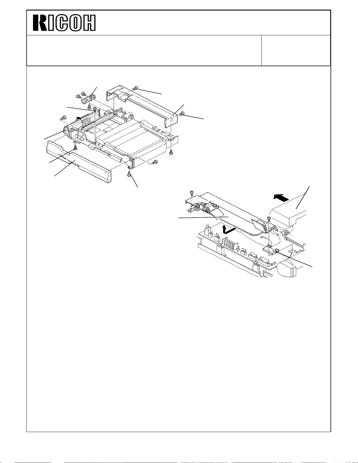
Technical Bulletin No. RTB-019
SUBJECT: RDH Original Size Misdetection DATE:
February 15, 1994
PAGE: 4 of 10
REPLACEMENT PROCEDURE
[A]
[a]
[B]
[b]
[a]
[C]
[b]
[D]
[b]
[F]
1. Remove the cover [A] (2 screws).
2. Remove the rear cover [B]. (Remove 2 screws, loosen 2 screws [a].)
3. Open the f eed guide [C ].
4. Remove the front cover [D]. (Remove 2 screws, loosen 3 screws [b].)
5. Slide the exit unit [E] fully to the left.
6. Remove the bracket [F] (2 screws).
[E]
[G]
7. Replace the ROM [G].
NOTE: Be sure the ROM is set in correct direction. Confirm whether all ROM legs are
set in the socket correctly.
8. Turn on the DIP SW 1-1. (Other DIP SWs should be still off)
NOTE: If in this condition either UK (8" x 10") lengthwise or GT (8" x 101/2")
lengthwise size originals are set, RDH recognizes them as UK lengthwise size.
If DIP SW 1-1 is still off, the RDH recognizes them as GT lengthwise size.
9. Install the bracket [F].
Page 85

Technical Bulletin No. RTB-019
[G]
SUBJECT: RDH Original Size Misdetection DATE:
February 15, 1994
PAGE: 5 of 10
[C]
[B]
[D]
[A]
[E]
[F]
[G]
10. Remove the encoder assembly [A] (1 stepped screw).
11. Remove the bushing [B].
12. Remove the gear [C].
13. Remove the two screws [D] fixing the wire clamps.
NOTE: Do not pull the harness too strongly, otherwise the sensor [E] will be pulled out.
14. Move the main motor bracket [F] up and hold it (5 screws).
NOTE: This step is necessary to access the screw [G] behind this motor.
15. Remove 2 screws [G].
Page 86

Technical Bulletin No. RTB-019
[A]
SUBJECT: RDH Original Size Misdetection DATE:
February 15, 1994
PAGE: 6 of 10
[D]
16. Remove 2 screws [A].
[F]
[C]
[B]
[F]
[D]
[E]
[G]
17. Remove the pull out roller stay [B].
18. Remove the registration sensor bracket [C] (2 screws [D]).
19. Remove the original feed out stay [E] (2 screws [F]).
20. Remove the pull out roller [G].
Page 87

Technical Bulletin No. RTB-019
[C]
SUBJECT: RDH Original Size Misdetection DATE:
February 15, 1994
PAGE: 7 of 10
[A]
[C]
[D]
21. Completely wipe off the grease on the pull out roller shaft [A] with alcohol.
22. Remove inner springs (Silver) [B] and outer springs (Black) [C].
23. Replace 4 arms [D] (1 screw each).
24. Install inner springs (Silver) [B] and outer springs (Black) [C].
NOTE: Inner springs and outer springs are different, do not mix them.
[B]
[B]
Page 88

Technical Bulletin No. RTB-019
[D]
[C]
[H]
SUBJECT: RDH Original Size Misdetection DATE:
February 15, 1994
PAGE: 8 of 10
[B]
[E]
[E]
[E]
[A]
[G]
[I]
[F]
25. Assemble the original guide plate [A], the pull out roller [B], the original feed-out stay [C],
and the registration sensor bracket [D] as shown (4 screws [E])
26. Install the pull out roller stay [F] (4 screws).
NOTE: Before fixing the 4 screws, close the feed guide [G] so that the pull out roller
arms [H] locate above the projections [I] on the feed guide.
Page 89

Technical Bulletin No. RTB-019
SUBJECT: RDH Original Size Misdetection DATE:
February 15, 1994
PAGE: 9 of 10
[A]
This should be a
short gold
colored screw
[B]
[D]
[C]
OK
[E]
27. Install the main motor bracket [A] (5 screws).
28. Fix the wire cramps [B] (2 screws).
29. Install the gear [C].
30. Install the bushing [D].
31. Install the encoder assembly [E] (1 stepped screw).
NOTE: 1. Make sure that the stepped screw [F] is correctly tightened as shown.
2. Make sure that the sensor [G] is set on the bracket properly.
[G]
[F]
NO
Good
Page 90

Technical Bulletin No. RTB-019
SUBJECT: RDH Original Size Misdetection DATE:
February 15, 1994
PAGE: 10 of 10
[C]
[B]
[A]
32. Install the front cover [A] (5 screws).
33. Install the rear cover [B] (4 screws).
34. Install the cover [C] (2 screws).
Page 91

Technical Bulletin No. RTB-020
SUBJECT: Manual Correction DATE:
February. 15, 1994
PAGE: 1 of 2
PREPARED BY: S. Mano
CHECKED BY:
CLASSIFICATION:
Action Required
Troubleshooting
Retrofit Information
Revision of service manual
Information only
Other
FROM: Copier Technical Support Section
MANUAL CORRECTION
Page 4-59 DUAL JOB FEEDER Preventive Maintenance Schedule
Incorrect
EM 120K 240K 360K NOTE
DUAL JOB FEEDER (for originals)
Transport Belt
Pick-up Roller
Feed Roller
Separation Belts
CRRR
CCCC
CRRR
CRRR
Belt cleaner. Replace if
necessary.
Alcohol. Replace if
necessary.
Alcohol. Replace if
necessary.
Alcohol. Replace if
necessary.
MODEL: F400 DJF
Correct
DUAL JOB FEEDER (for copies)
Transport Belt
Pick-up Roller
Feed Roller
Separation Belts
EM 120K 240K 360K NOTE
CRRR
CCCC
CRRR
CRRR
Belt cleaner. Replace if
necessary.
Alcohol. Replace if
necessary.
Alcohol. Replace if
necessary.
Alcohol. Replace if
necessary.
Page 92

Technical Bulletin No. RTB-020
SUBJECT: Manual correction DATE:
February 15, 1994
PAGE: 2 of 2
Each parts’s actual estimated life is 48K original feed times.
Since estimated average copies per one original is 2.5, we recommend to replace the
transport belt, separation belts and feed roller at the same time as the copier’s 120K PM.
(48,000 x 2.5 = 120, 000)
Because the F400/F410 series has an SP mode PM counter (indicates the original feed
time since the last PM), you can recognize how many times originals have been fed since
the last PM parts replacement. We recommend utilizing this function to manage the PM
parts replacement interval.
Therefore, if you utilize PM counter for original feed ( 9 PM COUNTER CLEAR PAGE4),
the PM table is as follows:
EM 48K 96K 144K NOTE
DUAL JOB FEEDER (for originals)
Transport Belt
Pick-up Roller
Feed Roller
Separation Belts
CRRR
CCCC
CRRR
CRRR
Belt cleaner. Replace if
necessary.
Alcohol. Replace if
necessary.
Alcohol. Replace if
necessary.
Alcohol. Replace if
necessary.
Concerning the RDH, the copy volume and original feed times are almost the same.
We just recommend to replacing PM parts at the same time as the copier’s 120K PM
(transport belt: replace at every copier’s 240K PM).
Page 93

Technical Bulletin No. RTB-021
SUBJECT: Vertical Black Line DATE:
February 15, 1994
PAGE: 1 of 1
PREPARED BY: S. Mano
CHECKED BY:
CLASSIFICATION:
Action Required
Troubleshooting
Retrofit Information
When installing a cleaning blade, be sure not to deform the side seals at both sides of the
cleaning blade.
If there is gap between the cleaning blade [A] and the side seals [B], it is possible that the
air flows from the front side [C] to the back side [D] of the cleaning blade through the gap.
This air flow carries a small amount of toner to the back side of the cleaning blade and it
gradually accumulates. This accumulated toner sometimes drops on the drum to create
vertical black lines [E].
Correct Condition
Revision of service manual
Information only
Other
[B]
FROM: Copier Technical Support Section
MODEL: RDH for F400
[E]
Incorrect Condition
Drum
[A]
[D]
Drum
If such vertical black lines appear:
1. Clean the back side of the cleaning blade.
2. Apply setting powder or toner on the side seals where they touch the cleaning blade.
3. Install the cleaning blade.
4. Confirm that the cleaning blade is not deformed.
Drum
[C]
Drum
Page 94

Technical Bulletin No. RTB-022
SUBJECT: Scanner flat cable, Lens cover installation DATE:
February. 15, 1994
PAGE: 1 of 1
PREPARED BY: S. Mano
CHECKED BY:
CLASSIFICATION:
Action Required
Troubleshooting
Retrofit Information
When installing the lens unit cover [A] or the scanner flat cable [B], confirm that these
parts are not touching.
The position of the scanner flat cable and the lens unit cover varies slightly because the
screw (positioning pin) hole diameter is slightly larger than the diameter of the fixing screw
(positioning pin).
If the scanner flat cable and the lens unit cover are installed at the closest position, it is
possible that the scanner flat cable and the lens unit cover touch, resulting in rubbing
noise during scanning.
If this occurs:
1. Loosen the two screws [C] fixing the lens unit cover.
2. Pull the lens unit cover [A] to the front.
Revision of service manual
Information only
Other
FROM: Copier Technical Support Section
MODEL: RDH for F410
3. Tighten two screws [C].
4. Loosen the screw [D] fixing the scanner flat cable.
5. Turn the scanner flat cable counterclockwise (it can rotate just a little).
6. Tighten the screw [D].
[D]
[B]
[C]
[A]
[B]
[A]
Page 95

Technical Bulletin No. RTB-023
SUBJECT: Sorter Stapler (Matt20)
Paper Exit Jam
PREPARED BY: J. Mochizuki
CHECKED BY:
CLASSIFICATION:
Action Required
Troubleshooting
Retrofit Information
FROM: 2nd Technical Support Section
Revision of service manual
Information only
Other
MODEL:
F400/F4 10
DATE: Feb.15,’94
PAGE: 1 of 2
Symptom:
In Sort/Stack mode, when copy paper is fed out to a bin, the roller drive motor speed
becomes higher. The motor occasionally hesitates at that moment, paper exit jam occurs.
Possible Cause:
The load of the roller drive motor is too large. The friction between the shafts and bearings
exceeds the roller drive motor torque.
Action Required:
1. Lubricate the the following parts using launa oil.
1) Between the bushings [A] and shafts
2) Between the exit rollers [B] and the shafts [C]
[B]
[C]
[A]
[A]
Page 96

Technical Bulletin No. RTB-023
SUBJECT: Sorter Stapler (Matt20)
Paper Exit Jam
We recommend to do this lubrication at every PM.
EM 120K 240K 360K NOTE
Bushings and exit
rollers
2. Reduce the timing belt tension.
1) Remove the proof tray.
2) Remove the rear cover.
3) Loosen the screws fixing the roller drive motor [A] bracket.
4) Slightly reduce the timing belt [B] tension, and retighten the screw.
Note: After reducing the belt tension, make A3 size copies in normal mode
to make sure no belt jumping.
LLL
DATE: Feb. 15,’94
PAGE: 2 of 2
Use Launa oil
[B]
[A]
Page 97

Technical Bulletin No. RTB-024
SUBJECT: USER / SERVICE REMARKS DATE: Mar 15 ’94
PAGE: 1 of 5
PREPARED BY:S. MANO
CHECKED BY: S. Hamano
CLASSIFICATION:
Action Required
Troubleshooting
Retrofit Information
Revision of service manual
Information only
Other
FROM: 2nd Technical Support Section
MODEL:F400/F410
USER/SERVICE REMARKS
This RTB is to inform you about some recently reported errors in service or operation. In
order to avoid unnecessary service calls please read the following carefully.
1. Developer (TD sensor) initial setting. (Refer to page 3-11 of
service manual)
SERVICE REMARKS
When performing the developer initial setting, do not make any copies until completing
developer (TD sensor) initial setting.
Do not forget to perform the developer (TD sensor) initial setting when replacing the
developer.
When the TD sensor is replaced, install new developer and perform developer initial
setting.
SYMPTOM IN THE CASE OF A MISTAKE
Image density control (toner concentration control) becomes abnormal resulting in over
toning, toner scattering or light copying.
CAUSE
As explained in page 2-12 and 2-13 of the service manual, the machine adjusts the TD
sensor output by using a new package of developer (toner concentration of the new
developer is exactly adjusted to 2 weight %: 20 g of toner in 1000g of developer).
The Vref (toner supply reference data) is also decided by developer initial setting.
After copies are made, the toner concentration changes.
If the developer initial setting is performed under this condition, Vref becomes abnormal
resulting in abnormal toner density control.
The characteristics of the developer vary depending on the production lot and the Vref
data is varied depending on these characteristics. If the developer initial setting is not
performed when the new developer is installed, the machine uses the Vref data which was
decided by using the previous toner. This can also cause abnormal toner density control.
Page 98

Technical Bulletin No. RTB-024
SUBJECT: USER / SERVICE REMARKS DATE: Mar 15 ’94
PAGE: 2 of 5
2. Tandem tray paper capacity
(Refer to page 67 of operating instructions)
USER REMARK
In the case where the paper is too thick, do not stack the paper over the limit mark [A]
even if there are less than 500 sheets.
[A]
SYMPTOM IN THE CASE OF A MISTAKE
Basically, the capacity of the tandem trays are 500 sheets each.
However, if the paper is thick, sometimes the paper level will be over the limit mark [A]
when one pack (500) of paper is set on the tandem tray.
In this case, it is possible that when the sheets on the Tandem left tray are transported to
the right tray (especially when paper is curled), some sheets may be caught by the press
arms [B]. This causes a paper jam.
[B]
[B]
Page 99
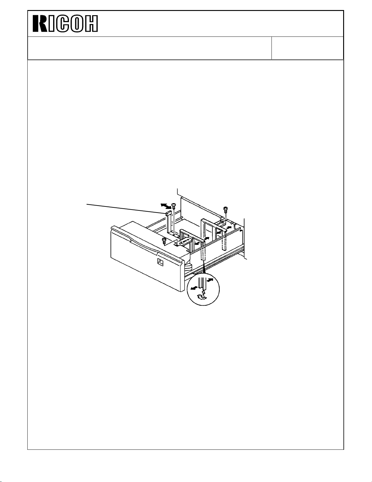
Technical Bulletin No. RTB-024
SUBJECT: USER / SERVICE REMARKS DATE: Mar 15 ’94
PAGE: 3 of 5
3-1. Built-in LCT (1.5K LCT) - No.1
SERVICE REMARKS
Do not set A3 size paper on the built-in LCT (1.5K sheets LCT).
DETAILS
A3 size can be selected by SP mode special feature page 6. However, because the end
fence [A] position cannot be shifted to A3 size position, A3 size sheets cannot be
mechanically set on the built-in LCT.
[A]
During field survey, we found some cases that the A3 paper is set in built-in LCT by
eliminating the end fence. However, this is prohibited for the following two reasons:
1. The top sheet, which is returned to the tray by the FRR mechanism, cannot be stopped
by end fence resulting in paper misfeed.
2. Too heavy paper will apply too much load to the LCT lift motor resulting in motor
damage. (SC504)
Page 100

Technical Bulletin No. RTB-024
SUBJECT: USER / SERVICE REMARKS DATE: Mar 15 ’94
PAGE: 4 of 5
3-2. Built-in LCT (1.5K LCT) - No.2
USER REMARKS
For the built-in LCT (1.5K LCT), do not set the paper at the left side of the end fence.
DETAILS
Because the customer sets two sets of sheets on the left and right tandem tray, it is
possible that the customer will mistakenly think that two sets of paper can be also loaded
in the built-in LCT.
If the paper is set at the left side, since there is no paper level detection for the paper in
the wrong position, the LCT motor will try to raise the paper even though the paper is
already in the highest position. This also creates SC504.
Note: If the SC504 occurs frequently, this gives extra electrical load to the LCT lift motor.
If the motor become defective, mostly the fuse [A] (F1: just beside the 5 pins
connector on the PCB on the lift motor: AX060051) is open. We have registered
the fuse as a service part. The part number is A0969522. Please refer to MB
No.10.
[A]
 Loading...