

Page 1

Technical Bulletin No. RTB-002
SUBJECT: Paper Jam DATE: Oct. 15 ’93
PAGE: 1 of 1
PREPARED BY: Shun Satoh
CHECKED BY: S. Hamano
CLASSIFICATION:
Action Required
Troubleshooting
Retrofit Information
Symptom:
1) High frequency of misfeeds (no feed from the paper tray), or paper jams in the
separation area and the fuser exit area.
2) Double sheet or shingle feed.
3) Noise when paper is being fed.
Cause:
Paper rising too high over the pick-up roller (all three feed stations). The initial paper lift
timing (when the paper cassette is inserted) is normal, however the subsequent lifts are
too long in duration - the lift motor does not turn off quickly enough. This may result in no
paper feed or in multiple sheets (stack or paper) being fed to the feed and separation
rollers and inconsistent paper separation or feed.
Revision of service manual
Information only
Other
FROM: Technical Support Department
MODEL: FT400i
Solution:
Replace the copier main ROM with A0895129.
Page 2

Technical Bulletin No. RTB-003
SUBJECT: Hot Roller Damage - Rotation lines DATE: Oct. 15 ’93
PAGE: 1 of 1
PREPARED BY: Shun Satoh
CHECKED BY: S. Hamano
CLASSIFICATION:
Action Required
Troubleshooting
Retrofit Information
Symptom:
Rotation lines or gouges on the hot roller that align with the position of the stripper pawls.
Cause:
When removing fuser unit jams, the customer may accidentally cause the stripper pawl
springs to pop off its metal anchor. Then, the top end of the stripper pawl might damage
the hot roller.
Revision of service manual
Information only
Other
FROM: Technical Support Department
MODEL: FT400i
FT500i
Solution:
1) To prevent the spring from popping off, the tab has been set at a 90 degree angle.
2) A stripper pawl stopper plate has also been implemented to limit the pawl movement
towards the hot roller even if the spring does come off. The new stripper pawls stopper
plate is P/N A0894460.
Page 3
Technical Bulletin No. RTB-004
REVISED ON June 15, 94
SUBJECT: Abnormal Hot Roller Worn Out DATE: Oct. 15 ’93
PAGE: 1 of 1
PREPARED BY: Shun Satoh
CHECKED BY: S. Hamano
CLASSIFICATION:
Action Required
Troubleshooting
Retrofit Information
Symptom:
Rotational wear or peeling of the hot roller surface prior to achieving the projected roller
yield of 120,000 copies.
Cause:
1) Fusing oil does not supply to the hot roller.
2) Paper separation jams from the hot roller.
3) The pressure of the oil blade might not be even or equal on and across the hot roller.
Solution:
Revision of service manual
Information only
Other
FROM: Technical Support Department
MODEL: FT400i
FT500i
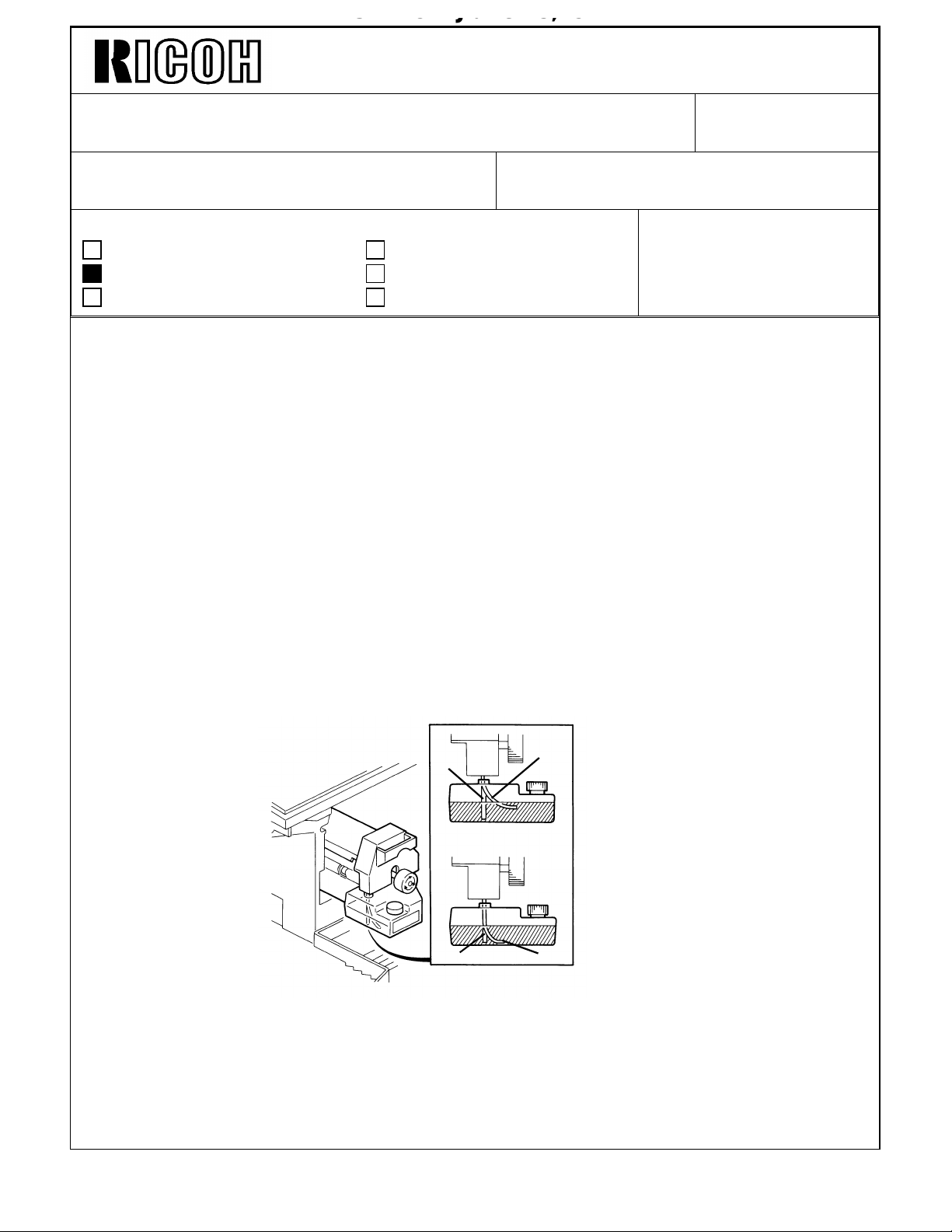
1) Confirm proper positioning of the oil supply tube [A] in the oil supply tank. The hose
must be positioned in the same recess in the oil tank as the oil end sensor [B].
Improper hose positioning away from the sensor will result in no oil being pumped
because the sensor detects oil in its recess when the other areas of the tank are empty.
[B]
No Good
[B] [A]
Good
2) Adjust the leading edge registration from -2 +/- 2 mm (factory setting) to -4 +/- 2 mm by
using SP mode 4-930. The additional 2 mm of erase (if possible - base it on customer
application) will further ensure proper separation of the paper from the hot roller.
[A]
3) The oil blade and the bracket were assembled at the factory to apply even pressure to
the hot roller. The new part number for this assembly is A1084017.
Page 4
Technical Bulletin No. RTB-005
SUBJECT: Separation Jam DATE: Oct. 15 ’93
PAGE: 1 of 1
PREPARED BY: Shun Satoh
CHECKED BY: S. Hamano
CLASSIFICATION:
Action Required
Troubleshooting
Retrofit Information
Symptom:
1) Jamming in the separation roller area.
2) Rotational groove in the separation roller
Cause:
1) Lower turn belt pulley positioned towards the front of the separation roller resulting in
the edge of the turn belt contacting the roller surface and creating a groove.
2) Flat spots in the separation roller due to manufacturing defects.
Revision of service manual
Information only
Other
FROM: Technical Support Department
MODEL: FT400i
FT500i
Solution:
1) The spring that positions the pulley has been changed to a smaller one to ensure a flat
contact of the turn belt on the separation roller. The purpose of this spring is to prevent
the trailing edge of A3 paper from contacting the cleaning unit casing. This could result
in smear or smudge marks. The new part number of this spring is AA063267.
2) The separation roller is changed to one already used for other models. The new part
number is AF021006.
Page 5

Technical Bulletin No. RTB-006
SUBJECT: Multiple feeding from the first feed station DATE: Oct.15 ’93
PAGE: 1 of 1
PREPARED BY: Shun Satoh
CHECKED BY: S. Hamano
CLASSIFICATION:
Action Required
Troubleshooting
Retrofit Information
Symptom:
Multiple feeding from the first feed station
Cause:
The pressure between the feed roller and the separation roller is not enough even if the
spring hook position is the right side hook.
Solution:
Revision of service manual
Information only
Other
FROM: Technical Support Department
MODEL: FT400i
FT500i
1) Cut three turns of the separation roller tension spring, and hook it to the center of the
spring hook. If necessary change the spring position to the right or left hook.
2) Add the additional spring hook bracket above the current hook bracket to increase
tolerance on the mass-production units.
Page 6

Technical Bulletin No. RTB-007
SUBJECT: Lines on half tone image area DATE: Oct. 15 ’93
PAGE: 1 of 1
PREPARED BY: Shun Satoh
CHECKED BY: S. Hamano
CLASSIFICATION:
Action Required
Troubleshooting
Retrofit Information
Symptom:
White lines on half tone image area
Cause:
Due to toner smudges behind the cleaning blade edge, the developer on the surface of the
drum is not removed completely from the drum by the cleaning blade. This means that
there are developer lines on the drum surface after the cleaning. This results in uneven
drum charge by the charge corona wire. This uneven drum charge makes white lines on
half tone images.
Revision of service manual
Information only
Other
FROM: Technical Support Department
MODEL: FT400i
FT500i
Solution:
1) Change the setting of the cleaning blade momentary release mode from "ON" to "OFF".
(SP mode 2-503)
2) Clean the cleaning blade edge with a soft cloth at every service call.
Page 7

Technical Bulletin No. RTB-008
[A]
SUBJECT: Oil roller shaft bushing is worn out DATE: Feb. 15,’94
PAGE: 1 of 1
PREPARED BY: J. Mochizuki
CHECKED BY:
CLASSIFICATION:
Action Required
Troubleshooting
Retrofit Information
Revision of service manual
Information only
Other
FROM: 2nd Technical Support Section
MODEL: FT400i
FT500i
Symptom:
The bushing [A] of the oil supply roller shaft is worn out.
Cause:
There is a gap between the oil supply roller flange [B] and the bearing [C]. This allows the
oil supply roller [D] to slide sideways, resulting that the engagement of the flange [B] and
the oil supply roller [D] becomes loose. As a consequence, the oil supply roller is pushed
in the arrow direction, and clamps the bushing [A] with the gear [E] when the oil supply
roller rotates.
The bushing [A] of the oil supply roller shaft is worn out due to friction between the
bushing and the gear [E] when the roller rotates.
Solution:
1.To modify the machines in the field, insert the washer (AA132019) [F] between the gear
[E] and the bushing [A] to remove the space between the oil supply roller flange and the
bearing.
2. From the November ’93 production, the oil supply roller shaft (A0894119) [G] has been
shortened by 1 mm to remove the space between the oil supply roller flange and the
bearing. The part number of the shaft remains the same.
[C]
[B]
[D]
[E]
[G]
[F]
Page 8

Technical Bulletin No. RTB-008
L1
L2
SUBJECT: DRUM Replacement Procedure DATE: July 31, ’94
PAGE: 1 of 8
PREPARED BY: F. Noguchi
CHECKED BY: S. Hamano
CLASSIFICATION:
Action Required
Troubleshooting
Retrofit Information
To prevent the drum from being damaged off by installation and removal, we have
prepared the drum protection mylar (P/N A0899502) as a service part.
PREPARATION OF THE DRUM PROTECTION MYLAR
256 ±0.5mm
[D]
Revision of service manual
Information only
Other
[A]
FROM: 2nd Technical Support Section
MODEL: SP40/50
(FT400i / 500i)
[C]
Gap [F]=L1+L2=
4.0 ∼ 5.0mm
[F]
[E]
[B]
1. Put a marks [A] on the drum protection mylar [B] using a felt pen as shown.
2. Wrap the mylar around the drum [C]. Align the mark [A] and the leading edge [D].
3. Peel off the cover of the adhesive tape [E], and stick the mylar to make a sleeve.
NOTE: The gap [F] (L1 + L2) between the mylar and the drum should be between 4.0mm
and 5.0mm.
If the gap is less than 2mm, the drum can not be sheathed and unsheathed
smoothly.
4. Remove the drum protection mylar from the drum.
Page 9

Technical Bulletin No. RTB-008
[E]
SUBJECT: DRUM Replacement Procedure DATE: July 31, ’94
PAGE: 2 of 8
DRUM REMOVAL PROCEDURE
[A]
[C]
[B]
[D]
CAUTION: The development unit should be seated in its home position when removing
the drum.
1. Remove the dispersant bottle holder [A] (1 snap ring).
2. Unplug the cleaning station tube fitting [B] from the developer tank (1 screw).
3. Lower the transfer corona unit by turning the transfer unit lever [C] clockwise.
4. Remove the change corona unit [D] ( 1 screw).
5. Remove the drum stay [E] (1 knob screw).
Page 10

Technical Bulletin No. RTB-008
SUBJECT: DRUM Replacement Procedure DATE: July 31 ’94
PAGE: 3 of 8
[A]
[B]
6. Pull out the cleaning unit [A] while keeping the unit away from the drum by turning it
clockwise.
NOTE: After pulling out the cleaning unit halfway, hold it with both hands.
7. Remove the drum flange [B].
Page 11

Technical Bulletin No. RTB-008
[A]
SUBJECT: DRUM Replacement Procedure DATE: July 31 ’94
PAGE: 4 of 8
[B]
[A]
8. Install the drum protection mylar [A].
NOTE: The inside of the drum protection mylar should be cleaned before installation.
9. Slide the drum guide [B] forward until it is latched.
Page 12

Technical Bulletin No. RTB-008
SUBJECT: DRUM Replacement Procedure DATE: July 31, ’94
PAGE: 5 of 8
[A]
10. Remove the drum [A] with the drum protection mylar and put it on a clean sheet of
paper.
NOTE: When pulling out the drum halfway, hold it by with both hands.
11. Remove the drum protection mylar from the drum. Wipe off the residue of the
dispersant from the mylar with clean cloth.
NOTE: If the mylar is dirty with the dispersant, the drum can not be sheathed and
unsheathed smoothly.
Page 13

Technical Bulletin No. RTB-008
[A]
SUBJECT: DRUM Replacement Procedure DATE: July 31, ’94
PAGE: 6 of 8
DRUM INSTALLATION PROCEDURE
[A]
[B]
[C]
1. Clean the drum protection mylar [A].
CAUTION : Do not touch the drum surface by bare hands. If you touch the drum surface
by bare hands, clean finger prints off of the drum immediately by using soft cloth
soaked with the dispersant.
2. Cover the drum [B] with the drum protection mylar as shown.
3. Slide the drum guide [C] forward until it is latched.
4. Carefully insert the drum along the drum guide [C].
Page 14

Technical Bulletin No. RTB-008
SUBJECT: DRUM Replacement Procedure DATE: July 31, ’94
PAGE: 7 of 8
[A]
[A]
[B]
[A]
[B]
5. Install the drum flange [A].
6. While holding the flange [A], pull out the drum protection mylar [B].
[C]
7. Pull out the drum protection mylar completely while holding the flange by using a scale
[C] or similar long object.
Page 15

Technical Bulletin No. RTB-008
SUBJECT: DRUM Replacement Procedure DATE: July 31, ’94
PAGE: 8 of 8
[D]
[C]
[B]
8. Hook the cleaning unit [B] on the guide rail [C] and slide in the cleaning unit while
turning it clockwise.
NOTE: If the cleaning unit cannot be seated completely, push the cleaning unit while
turning the knob screw [D] clockwise.
9. Reinstall all the removed parts.
 Loading...