

Page 1
MODIFICATION BULLETIN NO. 1 Page 1 of 1 ISSUED ON: November 15, ’92
Model SP40 Volt/Hz
Modified Article Fusing Unit
Reason for
Part catalog corrections
Modification
Please correct your parts catalo g as follows:
Incorrect P/N Correct P/N Description Index No. Page
AA060404 AA060493 Spring 37 37
52064390 AB013739 Gear - 20T 81 35
Date of
Modification
Serial Number
T. Ito, Manager
Copier Technical Support
Page 2
MODIFICATION BULLETIN NO. 2 PAGE 1 OF 4
ISSUED ON: June 30, ’93
Model SP40 / 50 Volt/Hz
Modified Article Parts Catalog for the SP50
Reason for
SP50 Unique Parts
Modification
Draw
No.
Old Parts
No.
New Parts
No.
A1081311 Upper Cover 0 → 1137
A1081276 Rear Cover 0 → 1177
A1085120 Main Board 0 → 1347
A0011897 Front Cover - Terminal 0 → 11811
AX530013 Exposure Lamp 0 → 11911
A1081667 Wire Fixing Plate 0 → 12211
Description Rank
Q’ty Used
Old → New
Inter-
change-
ability
Date of
Modification
Part needed for replacement by new part
Part No. Description No. Page
Serial
Number
Parts
Catalog
A1081650 First Scanner 0 → 12511
AW110013 Thermostat 0 → 12811
A1085396 Halogen Lamp Harness 0 → 12911
Not used Optics Fan Cover 1 → 05411
Rank: A : Replace with new parts immediately.B : Replace with new parts at time of repair.C : Replace with new parts at time of overhaul.
I nterchangeability:
(1) When old and new parts are not mutually interchangeable, use additional parts or an assembly part as indicated in "Parts needed for
replacement by new part" to install the new part.
(2) The mark to the left of the slash indicates whether the old part can be used in the new machine, and the mark to the right indicates whether
the new part can be used in the old machine. x = Not interchangeable o = Interchangeable
Page 3

MODIFICATION BULLETIN NO. 2 PAGE 2 OF 4
ISSUED ON: June 30, ’93
Draw
No.
Old Parts
No.
New Parts
No.
AX020024 Cooling Blower 0 → 15511
A0015465 Interface Harness 0 → 1 * 69 11
A1085395 Halogen Lamp Harness 0 → 15811
A1081112 Pulley 0 → 13421
AB013799 Gear - 33Z 0 → 13721
AX500045 Erase Lamp 0 → 1729
A1082002 Charge & Quenching Unit 0 → 14529
AA060531 Spring 0 → 22437
A1084111 Pressure Lever 0 → 22537
AX030005 Main Motor 0 → 11739
AB013813 Gear - 25Z 0 → 21839
Description Rank
Q’ty Used
Old → New
Inter-
change-
ability
Part needed for replacement by new part
Part No. Description No. Page
Parts
Catalog
07413808 Ball Bearing - 8 x 16 x 5 mm 0 → 61939
A1081136 Drive Arm - Fusing Exit 0 → 12639
AB013812 Gear 30Z 0 → 22839
A1085302 DC Power Supply Unit 0 → 11341
A1085422 Left DC Harness 0 → 11441
Page 4

MODIFICATION BULLETIN NO. 2 PAGE 3 OF 4
ISSUED ON: June 30, ’93
Draw
No.
Old Parts
No.
New Parts
No.
AX640032 Cooling Fan 1 → 22341
16061936 Capacitor - 8mF - 220V 0 → 1 * 28 41
A1085460 Relay Harness 0 → 1 * 29 41
AX640040 Cooling Fan 0 → 1 * 30 41
A1081175 Cooling Fan Bracket 0 → 1 * 31 41
AZ320066 Power Pack 0 → 11143
A1081885 Right Stay 0 → 1845
A1081154 Shielding Plate - DC Power 0 → 12845
A1085129 IC - AM27C512 - 155DC 0 → 1249
A1085141 IC - AM27C256 - 155DC 0 → 1349
Description Rank
Q’ty Used
Old → New
Inter-
change-
ability
Part needed for replacement by new part
Part No. Description No. Page
Parts
Catalog
Page 5
MODIFICATION BULLETIN NO. 2 PAGE 4 OF 4
DETAILS OF MODIFICATION
The SP50 design is based on the SP40. Please add these uniq ue parts in the SP40 parts catalog.
The SP50 stand alone parts catalo g is not plan ne d to be published.
Please refer SP40/50 RTB#001 for details.
30
ISSUED ON: June 30, ’93
23
31
Page 40
29
28
T. Ito, Manager
Copier Technical Support
T. Ito, Manager
Copier Technical Support
Page 6
MODIFICATION BULLETIN NO. 3 PAGE 1 OF 1
ISSUED ON: July 15, ’93
Model SP40 / 50 Volt/Hz
Modified Article
Reason for
Parts catalog correction
Modification
Inter-
Incorrect P/N Correct P/N Description Q’ty Used
A0893999 Not used Spacer - 3 x 6 x 0.1 31 29
change-
ability
Parts Catalog
Index No. Page
Date of
Modification
Serial Number
Page 7
T. Ito, Manager
Copier Technical Support
MODIFICATION BULLETIN NO. 4 PAGE 1 OF 1
ISSUED ON: July 15, ’93
Model SP40 / 50 Volt/Hz
Modified Article Drum Section / Frame Section
A089-15 3920600043
Reason for
To prevent uneven images in transparency mode
Modification
Date of
Modification
To prevent uneven images in transparency mode, two seals are added to change the air flow from the fusing unit.
This is because the silicon gas from the fu sing unit makes the charge wire dirty.
P/N Description Q’ty Used Page Index
A0892118 Charge Corona Seal 0 → 1 29 * 50
A0892117 Seal - 6 x 7 x 280 0 → 1 45 * 33
* : New Index
Serial Number
Page 8
MODIFICATION BULLETIN NO. 5 PAGE 1 OF 1
ISSUED ON: July 15, ’93
Model SP40 Volt/Hz
Modified Article Frame Section
Reason for
Part Standardization
Modification
Old P/N New P/N Description
A0891860 A1081860 Front Optics Frame 1 → 1 O/O 3 45
A0891153 A1081153 Shielding Plate 1 → 1 O/O 26 45
Q’ty Used
Old → New
Inter-
change-
ability
Parts Catalog
Index No. Page
Date of
Modification
Serial Number
T. Ito, Manager
Copier Technical Support
Page 9
MODIFICATION BULLETIN NO. 6 PAGE 1 OF 2
ISSUED ON: October 15, ’93
Model SP40 / 50 Volt/Hz
Modified Article Timing Belt Tightener
Reason for
To prevent noise from the drive section
Modification
Inter-
Old P/N New P/N Description Q’ty Used
A0891120 A0891123 Tightener Pulley
1 → 1
change-
ability
X/O 45 37
Index No. Page
Date of
Modification
Parts Catalog
To prevent the possibility t ha t th e tig htener pulley hits the pulse gen era tor, the thickness of the pu lley is re du ced .
Serial Number
S. Hamano, Manager
Technical Support Department
Page 10

MODIFICATION BULLETIN NO. 6 PAGE 2 OF 2
ISSUED ON: October 15, ’93
MODEL NAME
Savin 9040 i 115/60 USA, Canada A089-15 3930300001
Ricoh FT400 i 110/60 Taiwan A089-19 A3273030001
Ricoh FT400 i 220/50 Asia, Oceania A089-29 A3273030001
Savin 9050 i 115/60 USA, Canada A089-15 1930300001
Ricoh FT500 i 110/60 Taiwan A089-19 A3333030001
Ricoh FT500 i 220/50 Asia, Oceania A089-29 A3333030001
V/Hz DESTINATION CODE SERIAL NUMBER
Page 11
MODIFICATION BULLETIN NO. 7 PAGE 1 OF 3
ISSUED ON: October 15, ’93
Model SP40 / 50 Volt/Hz
Modified Article Oil Blade
Reason for
Modification
Draw
No.
Old Parts
No.
52154117 A1084017 Oil Blade Ass’y 1 1 X/O 11 37
52154116 1 10 37
09513005W 3 102 37
To extend the hot roller yield
New Parts
No.
Description Rank
Q’ty Used
Old→New
Inter-
change-
ability
Date of
Modification
Parts needed for replacement by new part
Part No. Description No. Page
Serial
Number
Parts
Catalog
Rank: A : Replace with new parts immediately. B : Replace with new parts at time of repair. C : Replace with new parts at time of overhaul.
Interchangeability:
(1) When old and new parts are not mutually interchangeable, use additional parts or an assembly part as indicated in "Parts needed for
replacement by new part" to install the new part.
(2) The mark to the left of the slash indicates whether the old part can be used in the new machine, and the mark to the right indicates whether
the new part can be used in the old machine. x = Not interchangeable o = Interchangeable
Page 12
MODIFICATION BULLETIN NO. 7 PAGE 2 OF 3
ISSUED ON: October 15, ’93
DETAILS OF MODIFICATION
The pressure of the oil blade might not be even or equal across the hot roller. Due to uneven
pressure, the roller might be worn out soon er th an expe cted.
The oil blade and the bra cket were assembled at the factory to app ly even pressure to the hot roller.
New Part Number
A1084017
S. Hamano, Manager
Technical Support Department
Page 13

MODIFICATION BULLETIN NO. 7 PAGE 3 OF 3
ISSUED ON: October 15, ’93
MODEL NAME
Savin 9040 i 115/60 USA Canada A089-15 3930400001
Ricoh FT400 i 110/60 Taiwan A089-19 A3273040001
Ricoh FT400 i 220/50 Asia, Oceania A089-29 A3273040001
Savin 9050 i 115/60 USA Canada A089-15 1930400001
Ricoh FT500 i 110/60 Taiwan A089-19 A3333040001
Ricoh FT500 i 220/50 Asia, Oceania A089-29 A3333040001
V/Hz DESTINATION CODE SERIAL NUMBER
Page 14

MODIFICATION BULLETIN NO. 8 PAGE 1 OF 2
ISSUED ON: October 15, ’93
Model SP40 / 50 Volt/Hz
Modified Article Separator Roller
Reason for
Vendor change
Modification
Inter-
Old P/N New P/N Description Q’ty Used
AF020107 AF021006 Separator Roller
1 → 1
change-
ability
O/O 26 33
Date of
Modification
Parts Catalog
Index No. Page
Serial Number
S. Hamano, Manager
Technical Support Department
Page 15

MODIFICATION BULLETIN NO. 8 PAGE 2 OF 2
ISSUED ON: October 15, ’93
MODEL NAME
Savin 9040 i 115/60 USA Canada A089-15 3930400001
Ricoh FT400 i 110/60 Taiwan A089-19 A3273040001
Ricoh FT400 i 220/50 Asia, Oceania A089-29 A3273040001
Savin 9050 i 115/60 USA Canada A089-15 1930400001
Ricoh FT500 i 110/60 Taiwan A089-19 A3333040001
Ricoh FT500 i 220/50 Asia, Oceania A089-29 A3333040001
V/Hz DESTINATION CODE SERIAL NUMBER
Page 16

MODIFICATION BULLETIN NO. 9 PAGE 1 OF 3
ISSUED ON: October 15, ’93
Model SP40 / 50 Volt/Hz
Modified Article Main ROM
Reason for
Software change
Modification
Draw
No.
Old Parts
No.
A0895132 A0895129 IC - AM27C512 - 155DC
New Parts
No.
Description Rank
Q’ty Used
Old→New
1 → 1
Date of
Modification
Inter-
change-
ability
X/O 2 49
Parts needed for replacement by new part
Part No. Description No. Page
Serial
Number
Parts
Catalog
Rank: A : Replace with new parts immediately. B : Replace with new parts at time of repair. C : Replace with new parts at time of overhaul.
Interchangeability:
(1) When old and new parts are not mutually interchangeable, use additional parts or an assembly part as indicated in "Parts needed for
replacement by new part" to install the new part.
(2) The mark to the left of the slash indicates whether the old part can be used in the new machine, and the mark to the right indicates whether
the new part can be used in the old machine. x = Not interchangeable o = Interchangeable
Page 17
MODIFICATION BULLETIN NO. 9 PAGE 2 OF 3
ISSUED ON: October 15, ’93
DETAILS OF MODIFICATION
Old P/N New P/N Reason for modification
A0895132 A0895133
A0895133 A0895134
A0895134 A0895129
1. Corrects the malfunction of the sorter jam when the sorter adapter and the
MATT 20 are installed.
2. Feeds out all paper inside of the copier if a sorter jam occurs.
1. Selects the APS function automatically whenever originals are inserted in the DF.
2. Enables to select the LCT in the third feed station even if the paper end
condition occurs in the LCT.
3. Enables to rotate the main motor by SP mode.
4. When a user code is input to operate the copier, the operation panel mode
settings become the default settings.
1. The paper lift motor ON/OFF timing is changed to prevent no feeding or
multi-feedings.
2. Corrects the DF jam counter logging data in SP mode.
S. Hamano, Manager
Technical Support Department
Page 18

MODIFICATION BULLETIN NO. 9 PAGE 3 OF 3
ISSUED ON: October 15, ’93
MODEL NAME
Savin 9040 i 115/60 USA Canada A089-15 3930400001
Ricoh FT400 i 110/60 Taiwan A089-19 A3273040001
Ricoh FT400 i 220/50 Asia, Oceania A089-29 A3273040001
Savin 9050 i 115/60 USA Canada A089-15 1930400001
Ricoh FT500 i 110/60 Taiwan A089-19 A3333040001
Ricoh FT500 i 220/50 Asia, Oceania A089-29 A3333040001
V/Hz DESTINATION CODE SERIAL NUMBER
Page 19
MODIFICATION BULLETIN NO. 10 PAGE 1 OF 3
ISSUED ON: October 15, ’93
Model SP40 / 50 Volt/Hz
Modified Article Turn Belt Pulley Spring
Reason for
To minimize separation jams
Modification
Draw
No.
Old Parts
No.
AA063193 AA063267 Spring
New Parts
No.
Description Rank
Q’ty Used
Old→New
1 → 1
Date of
Modification
Inter-
change-
ability
X/O 8 29
Parts needed for replacement by new part
Part No. Description No. Page
Serial
Number
Parts
Catalog
Rank: A : Replace with new parts immediately. B : Replace with new parts at time of repair. C : Replace with new parts at time of overhaul.
Interchangeability:
(1) When old and new parts are not mutually interchangeable, use additional parts or an assembly part as indicated in "Parts needed for
replacement by new part" to install the new part.
(2) The mark to the left of the slash indicates whether the old part can be used in the new machine, and the mark to the right indicates whether
the new part can be used in the old machine. x = Not interchangeable o = Interchangeable
Page 20

MODIFICATION BULLETIN NO. 10 PAGE 2 OF 3
ISSUED ON: October 15, ’93
DETAILS OF MODIFICATION
The lower turn belt pulley is positioned towa rds th e fro nt of the sep ara tion roller resulting in the edge of
the turn belt contacting the roller surface and creating a groove. This might cause separation jams.
The spring that positions th e pu lley ha s bee n cha ng ed to a smalle r one to en sure flat contact of the
turn belt on the separation roller.
S. Hamano, Manager
Technical Support Department
Page 21

MODIFICATION BULLETIN NO. 10 PAGE 3 OF 3
ISSUED ON: October 15, ’93
MODEL NAME
Savin 9040 i 115/60 USA Canada A089-15 3930400001
Ricoh FT400 i 110/60 Taiwan A089-19 A3273040001
Ricoh FT400 i 220/50 Asia, Oceania A089-29 A3273040001
Savin 9050 i 115/60 USA Canada A089-15 1930400001
Ricoh FT500 i 110/60 Taiwan A089-19 A3333040001
Ricoh FT500 i 220/50 Asia, Oceania A089-29 A3333040001
V/Hz DESTINATION CODE SERIAL NUMBER
Page 22

MODIFICATION BULLETIN NO. 11 PAGE 1 OF 2
ISSUED ON: October 15, ’93
Model SP40 / 50 Volt/Hz
Modified Article Pick-off Pawl Slider
Reason for
To prevent the hot roller damage by pick-off pawls
Modification
Inter-
Old P/N New P/N Description Q’ty Used
A0894461 A0894462 Stopper Bracket
1 → 1
change-
ability
X/O 1 35
Parts Catalog
Index No. Page
Date of
Modification
If a spring for the pick-off pawl is removed accidentally, the to p en d of the pawl migh t da mage the hot roller. To
prevent this, stoppers are added on the pick-off pawl slider. This stopper limits the pawl movement towards the hot
roller even if the spring does come off.
Serial Number
S. Hamano, Manager
Technical Support Department
Page 23

MODIFICATION BULLETIN NO. 11 PAGE 2 OF 2
ISSUED ON: October 15, ’93
MODEL NAME
Savin 9040 i 115/60 USA, Canada A089-15 3930400001
Ricoh FT400 i 110/60 Taiwan A089-19 A3273040001
Ricoh FT400 i 220/50 Asia, Oceania A089-29 A3273040001
Savin 9050 i 115/60 USA, Canada A089-15 1930400001
Ricoh FT500 i 110/60 Taiwan A089-19 A3333040001
Ricoh FT500 i 220/50 Asia, Oceania A089-29 A3333040001
V/Hz DESTINATION CODE SERIAL NUMBER
Page 24

MODIFICATION BULLETIN NO. 12 PAGE 1 OF 2
ISSUED ON: October 15, ’93
Model SP40 / 50 Volt/Hz
Modified Article Fusing Thermistor
Reason for
Thermistor damage
Modification
Inter-
Old P/N New P/N Description Q’ty Used
A0895444 A0895445 Thermistor
1 → 1
change-
ability
X/O 30 37
Parts Catalog
Index No. Page
Date of
Modification
To prevent the mylar on the the rmisto r f rom peeling off, apply a special glue between the mylar and th e th ermistor.
Serial Number
S. Hamano, Manager
Technical Support Department
Page 25

MODIFICATION BULLETIN NO. 12 PAGE 2 OF 2
ISSUED ON: October 15, ’93
MODEL NAME
Savin 9040 i 115/60 USA, Canada A089-15 3930100001
Ricoh FT400 i 110/60 Taiwan A089-19 A3273010001
Ricoh FT400 i 220/50 Asia, Oceania A089-29 A3273010001
Savin 9050 i 115/60 USA, Canada A089-15 1930100001
Ricoh FT500 i 110/60 Taiwan A089-19 From First Production
Ricoh FT500 i 220/50 Asia, Oceania A089-29 From First Production
V/Hz DESTINATION CODE SERIAL NUMBER
Page 26

MODIFICATION BULLETIN NO. 13 PAGE 1 OF 2
ISSUED ON: October 15, ’93
Model SP40 / 50 Volt/Hz
Modified Article Separation Guide Plate
Reason for
Vendor change
Modification
Inter-
Old P/N New P/N Description Q’ty Used
A0893909 A0893908 Separation Guide Plate
1 → 1
change-
ability
O/O 27 33
Date of
Modification
Parts Catalog
Index No. Page
Serial Number
S. Hamano, Manager
Technical Support Department
Page 27

MODIFICATION BULLETIN NO. 13 PAGE 2 OF 2
ISSUED ON: October 15, ’93
MODEL NAME
Savin 9040 i 115/60 USA, Canada A089-15
Ricoh FT400 i 110/60 Taiwan A089-19
Ricoh FT400 i 220/50 Asia, Oceania A089-29
Savin 9050 i 115/60 USA, Canada A089-15
Ricoh FT500 i 110/60 Taiwan A089-19
Ricoh FT500 i 220/50 Asia, Oceania A089-29
V/Hz DESTINATION CODE SERIAL NUMBER
Page 28

MODIFICATION BULLETIN NO. 14 PAGE 1 OF 2
ISSUED ON: October 15, ’93
Model SP40 / 50 Volt/Hz
Modified Article By-pass table magnet
Reason for
To prevent the by-pass table from opening during operation
Modification
Inter-
Old P/N New P/N Description Q’ty Used
A0892785 52052734 Magnet
1 → 1
change-
ability
X/O 20 7
To prevent the by-pass ta ble from opening during opera tio n, a stronger magnet is used.
Date of
Modification
Parts Catalog
Index No. Page
Serial Number
S. Hamano, Manager
Technical Support Department
Page 29

MODIFICATION BULLETIN NO. 14 PAGE 2 OF 2
ISSUED ON: October 15, ’93
MODEL NAME
Savin 9040 i 115/60 USA, Canada A089-15 3930700001
Ricoh FT400 i 110/60 Taiwan A089-19 A3273070001
Ricoh FT400 i 220/50 Asia, Oceania A089-29 A3273070001
Savin 9050 i 115/60 USA, Canada A089-15 1930700001
Ricoh FT500 i 110/60 Taiwan A089-19 A3333070001
Ricoh FT500 i 220/50 Asia, Oceania A089-29 A3333070001
V/Hz DESTINATION CODE SERIAL NUMBER
Page 30

MODIFICATION BULLETIN NO. 15 PAGE 1 OF 2
ISSUED ON: October 15, ’93
Model SP40 / 50 Volt/Hz
Modified Article Separation Roller Spring Hook
Reason for
Multiple feeding from the first feed station
Modification
Inter-
Old P/N New P/N Description Q’ty Used
A1082572 Spring Hook Bracket
0 → 1
change-
ability
---- * 68 19
Date of
Modification
Parts Catalog
Index No. Page
Serial Number
* New index no.
The pressure between the feed ro ller and th e separation roller is not enough if rough edge cut pa per is used. This
results in multiple feeding . Add the add itio na l spring hook bracket above the current hook bracket to incre ase tolerance.
52
68
68
52
S. Hamano, Manager
Technical Support Department
Page 31

MODIFICATION BULLETIN NO. 15 PAGE 2 OF 2
ISSUED ON: October 15, ’93
MODEL NAME
Savin 9040 i 115/60 USA, Canada A089-15 3930600001
Ricoh FT400 i 110/60 Taiwan A089-19 A3273060001
Ricoh FT400 i 220/50 Asia, Oceania A089-29 A3273060001
Savin 9050 i 115/60 USA, Canada A089-15 1930600001
Ricoh FT500 i 110/60 Taiwan A089-19 A3333060001
Ricoh FT500 i 220/50 Asia, Oceania A089-29 A3333060001
V/Hz DESTINATION CODE SERIAL NUMBER
Page 32

MODIFICATION BULLETIN NO. 16 PAGE 1 OF 2
11 ± 1mm
ISSUED ON: October 15, ’93
Model SP40 / 50 Volt/Hz
Modified Article Si Oil Bottle Decal
Reason for
Request from OEM company
Modification
Inter-
Old P/N New P/N Description Q’ty Used
AA000084 AA000087 Decal - Oil Supply
1 → 1
change-
ability
O/O 10 59
Date of
Modification
Parts Catalog
Index No. Page
Serial Number
14 ± 1mm
<New Decal>
S. Hamano, Manager
Technical Support Department
Page 33

MODIFICATION BULLETIN NO. 16 PAGE 2 OF 2
ISSUED ON: October 15, ’93
MODEL NAME
Savin 9040 i 115/60 USA, Canada A089-15
Ricoh FT400 i 110/60 Taiwan A089-19
Ricoh FT400 i 220/50 Asia, Oceania A089-29
Savin 9050 i 115/60 USA, Canada A089-15
Ricoh FT500 i 110/60 Taiwan A089-19
Ricoh FT500 i 220/50 Asia, Oceania A089-29
V/Hz DESTINATION CODE SERIAL NUMBER
Page 34

MODIFICATION BULLETIN NO. 17 PAGE 1 OF 3
ISSUED ON: January 15, ’94
Model SP40 / 50 Volt/Hz
Modified Article Front Cover Stopper
Reason for
To ensure proper oil tank setting
Modification
Draw
No.
Old Parts
No.
A0891252 Door Cover - Lower Stopper
New Parts
No.
A0891249 Front Cover Stopper
Description Rank
Q’ty Used
Old→New
1 → 0
0 → 1
Date of
Modification
Inter-
change-
ability
X/O 41 7
Parts needed for replacement by new part
Part No. Description No. Page
Serial
Number
Parts
Catalog
41 7
Rank: A : Replace with new parts immediately. B : Replace with new parts at time of repair. C : Replace with new parts at time of overhaul.
Interchangeability:
(1) When old and new parts are not mutually interchangeable, use additional parts or an assembly part as indicated in "Parts needed for
replacement by new part" to install the new part.
(2) The mark to the left of the slash indicates whether the old part can be used in the new machine, and the mark to the right indicates whether
the new part can be used in the old machine. x = Not interchangeable o = Interchangeable
Page 35

MODIFICATION BULLETIN NO. 17 PAGE 2 OF 3
DETAILS OF MODIFICATION
If the oil tank is not set in the proper posit ion , th e colle cte d silicon e oil does no t ret urn to the tank,
and oil leakage might hap pe n. To preven t this, a bracket [A] has been add ed on th e front cover, so
that the cover cannot be close d if the oil tank is out of position.
[A]
ISSUED ON: January 15, ’94
[A]
Front Cover Stopper
S. Hamano, Assistant General Man ag er
Technical Support Department
Page 36

MODIFICATION BULLETIN NO. 17 PAGE 3 OF 3
ISSUED ON: January 15, ’94
MODEL NAME
Savin 9040 i 115/60 USA Canada A089-15 3931000001
Ricoh FT400 i 110/60 Taiwan A089-19 A327402XXXX
Ricoh FT400 i 220/50 Asia, Oceania A089-29 A3273090001
Savin 9050 i 115/60 USA Canada A089-15 1931000001
Ricoh FT500 i 110/60 Taiwan A089-19 A333402XXXX
Ricoh FT500 i 220/50 Asia, Oceania A089-29 A3333100001
V/Hz DESTINATION CODE SERIAL NUMBER
Page 37

MODIFICATION BULLETIN NO. 18 PAGE 1 OF 3
ISSUED ON: January 15, ’94
Model SP40 / 50 Volt/Hz
Modified Article Oil Supply Tube
Reason for
To ensure proper oil supply
Modification
Draw
No.
Old Parts
No.
AA180038 AA180052 Oil Supply Tube
52154411 Spring Plate
New Parts
No.
A0894218 Guide - Oil End Sensor
A0894217 Guide - Oil Supply
Description Rank
Q’ty Used
Old→New
1 → 1
1 → 0
0 → 1
0 → 1
Date of
Modification
Inter-
change-
ability
X/X X/O as a set 57 35
Parts needed for replacement by new part
Part No. Description No. Page
* New Index
Serial
Number
Parts
Catalog
67 35
*87 35
*88 35
Rank: A : Replace with new parts immediately. B : Replace with new parts at time of repair. C : Replace with new parts at time of overhaul.
Interchangeability:
(1) When old and new parts are not mutually interchangeable, use additional parts or an assembly part as indicated in "Parts needed for
replacement by new part" to install the new part.
(2) The mark to the left of the slash indicates whether the old part can be used in the new machine, and the mark to the right indicates whether
the new part can be used in the old machine. x = Not interchangeable o = Interchangeable
Page 38

MODIFICATION BULLETIN NO. 18 PAGE 2 OF 3
[A]
ISSUED ON: January 15, ’94
DETAILS OF MODIFICATION
After a machine has bee n use d fo r a long time , pa pe r powd er an d toner are mixed in the silicone oil, an d sink to the bottom
of the toner tank. If this pre cipitation is pumped up to be supp lied to th e fusing roller, it sticks on the oil sup ply pa d cau sing
insufficient oil supply to the fusin g roller.
To prevent this, the end po sitions of the oil end sensor [A] and the oil supp ly tub e [B ] ha ve be er raise d.
1. The length of the oil supply tube [B] has bee n cha nged from 105mm to 70mm
2. Two guides for the oil end sensor and the oil supply tube have been added.
3. The spring plate (pag e 35 , ind ex 29 ) h as been re move d.
NOTE: Set the two guides as shown [C].
Index 87
[B]
Index 88
[C]
S. Hamano, Assistant General Manager
Technical Support Department
Page 39

MODIFICATION BULLETIN NO. 18 PAGE 3 OF 3
ISSUED ON: January 15, ’94
MODEL NAME
Savin 9040 i 115/60 USA Canada A089-15 39402XXXXX
Ricoh FT400 i 110/60 Taiwan A089-19 A327402XXXX
Ricoh FT400 i 220/50 Asia, Oceania A089-29 A327402XXXX
Savin 9050 i 115/60 USA Canada A089-15 1940100001
Ricoh FT500 i 110/60 Taiwan A089-19 A333402XXXX
Ricoh FT500 i 220/50 Asia, Oceania A089-29 A333402XXXX
V/Hz DESTINATION CODE SERIAL NUMBER
Page 40

MODIFICATION BULLETIN NO. 19 PAGE 1 OF 2
ISSUED ON: January 15, ’94
Model SP40 / 50 Volt/Hz
Modified Article Fusing unit gears
Reason for
Modification
To increase durability
Date of
Modification
To increase durability, th e mat erial of the fusing unit gea rs has be en chan ge d. The gea r - 17Z has be en chan ge d to a
gear and bearing combina tio n.
Old P/N New P/N Description Q’ty Used
AB013651 A0894915 Gear - 18Z
AB013648 AB013901 Gear - 17Z
07413506 Ball Bearing - 6 x 12 x 4mm
115
1 → 1
1 → 1
0 → 1
17
Inter-
change-
ability
x/o 33 35
x/o as a set 17 37
Index No. Page
Parts Catalog
115 37
Serial Number
33
S. Hamano, Assistant General Manager
Technical Support Department
Page 41

MODIFICATION BULLETIN NO. 19 PAGE 2 OF 2
ISSUED ON: January 15, ’94
MODEL NAME
Savin 9040 i 115/60 USA Canada A089-15 3931200001
Ricoh FT400 i 110/60 Taiwan A089-19 A327402XXXX
Ricoh FT400 i 220/50 Asia, Oceania A089-29 A327402XXXX
Savin 9050 i 115/60 USA Canada A089-15 1940100001
Ricoh FT500 i 110/60 Taiwan A089-19 A333402XXXX
Ricoh FT500 i 220/50 Asia, Oceania A089-29 A3334010001
V/Hz DESTINATION CODE SERIAL NUMBER
Page 42

MODIFICATION BULLETIN NO. 20 PAGE 1 OF 3
ISSUED ON: January 15, ’94
Model SP40 / 50 Volt/Hz
Modified Article Oil Blade Ass’y
Reason for
To facilitate servicing
Modification
Draw
No.
Old Parts
No.
A1084017 A0899501 Oil Blade Ass’y
New Parts
No.
A0894110 Clip - Oil Blade
Description Rank
Q’ty Used
Old→New
1 → 1
0 → 2
Date of
Modification
Inter-
change-
ability
O/O 11 37
Parts needed for replacement by new part
Part No. Description No. Page
Serial
Number
Parts
Catalog
42 37
Rank: A : Replace with new parts immediately. B : Replace with new parts at time of repair. C : Replace with new parts at time of overhaul.
Interchangeability:
(1) When old and new parts are not mutually interchangeable, use additional parts or an assembly part as indicated in "Parts needed for
replacement by new part" to install the new part.
(2) The mark to the left of the slash indicates whether the old part can be used in the new machine, and the mark to the right indicates whether
the new part can be used in the old machine. x = Not interchangeable o = Interchangeable
Page 43

MODIFICATION BULLETIN NO. 20 PAGE 2 OF 3
ISSUED ON: January 15, ’94
DETAILS OF MODIFICATION
To make it possible to remove the oil blad e with ou t remo ving the oil supply roller, the span of the oil blade ass’y
[A] has been shortened. The oil blade can be removed if it is slid sideways, af te r removing the two newly added
clips [B].
[B]
[A]
S. Hamano, Assistant General Manager
Technical Support Department
Page 44

MODIFICATION BULLETIN NO. 20 PAGE 3 OF 3
ISSUED ON: January 15, ’94
MODEL NAME
Savin 9040 i 115/60 USA Canada A089-15 3931100101
Ricoh FT400 i 110/60 Taiwan A089-19 A327402XXXX
Ricoh FT400 i 220/50 Asia, Oceania A089-29 A327402XXXX
Savin 9050 i 115/60 USA Canada A089-15 1940100001
Ricoh FT500 i 110/60 Taiwan A089-19 A333402XXXX
Ricoh FT500 i 220/50 Asia, Oceania A089-29 A3334010001
V/Hz DESTINATION CODE SERIAL NUMBER
Page 45

MODIFICATION BULLETIN NO. 21 PAGE 1 OF 3
ISSUED ON: January 31, ’94
Model SP40/50 Volt/Hz
Modified Article Paper feed gear
Reason for
To facilitate servicing
Modification
Draw
No.
Old Parts
No.
AB017238 A0891104 Gear - 20Z/32Z
07403808 Bearing - 8 x 19 x 6mm
07403208 Bearing - 8 x 24 x 8mm
New Parts
No.
Description Rank
Q’ty Used
Old→New
1 → 1
1 → 0
1 → 0
Date of
Modification
Inter-
change-
ability
X/O 13 21
Parts needed for replacement by new part
Part No. Description No. Page
Serial
Number
Parts
Catalog
115 21
116 21
Rank: A : Replace with new parts immediately. B : Replace with new parts at time of repair. C : Replace with new parts at time of overhaul.
Interchangeability:
(1) When old and new parts are not mutually interchangeable, use additional parts or an assembly part as indicated in "Parts needed for
replacement by new part" to install the new part.
(2) The mark to the left of the slash indicates whether the old part can be used in the new machine, and the mark to the right indicates whether
the new part can be used in the old machine. x = Not interchangeable o = Interchangeable
Page 46

MODIFICATION BULLETIN NO. 21 PAGE 2 OF 3
DETAILS OF MODIFICATION
To facilitate service, the ge ar - 20Z/ 32 Z is to be asse mble d with the two bearings (07403808
and 07403208) to be sup plied as one.
13
116
13
115
ISSUED ON: January 31, ’93
S. Hamano, Assistant General Manager
Technical Support Department
Page 47

MODIFICATION BULLETIN NO. 21 PAGE 3 OF 3
ISSUED ON: January 31, ’93
MODEL NAME
Savin 9040 i 115/60 USA Canada A089-15
Ricoh FT400 i 110/60 Taiwan A089-19
Ricoh FT400 i 220/50 Asia, Oceania A089-29
Savin 9050 i 115/60 USA Canada A089-15
Ricoh FT500 i 110/60 Taiwan A089-19
Ricoh FT500 i 220/50 Asia, Oceania A089-29
V/Hz DESTINATION CODE SERIAL NUMBER
Page 48

MODIFICATION BULLETIN NO. 22 PAGE 1 OF 2
ISSUED ON: January 31, ’94
Model SP40 / 50 Volt/Hz
Modified Article Pressure Roller Spring (SP50 only)
Reason for
To facilitate manufacturing
Modification
To make the margin of clearance between the sprin g an d th e pa pe r e xit unit, the
diameter of the spring has been changed from 12.1mm to 9.6mm.
Inter-
Old P/N New P/N Description Q’ty Used
AA060531 AA060564 Spring
1 → 1
change-
ability
O/O 24 37
Parts Catalog
Index No. Page
Date of
Modification
Serial Number
S. Hamano, Assistant General Manager
Technical Support Department
Page 49

MODIFICATION BULLETIN NO. 22 PAGE 2 OF 2
V/Hz DESTINATION CODE SERIAL NUMBER
MODEL NAME
Savin 9040 i 115/60 USA Canada A089-15
Ricoh FT400 i 110/60 Taiwan A089-19
Ricoh FT400 i 220/50 Asia, Oceania A089-29
Savin 9050 i 115/60 USA Canada A089-15
Ricoh FT500 i 110/60 Taiwan A089-19
Ricoh FT500 i 220/50 Asia, Oceania A089-29
ISSUED ON: January 31, ’94
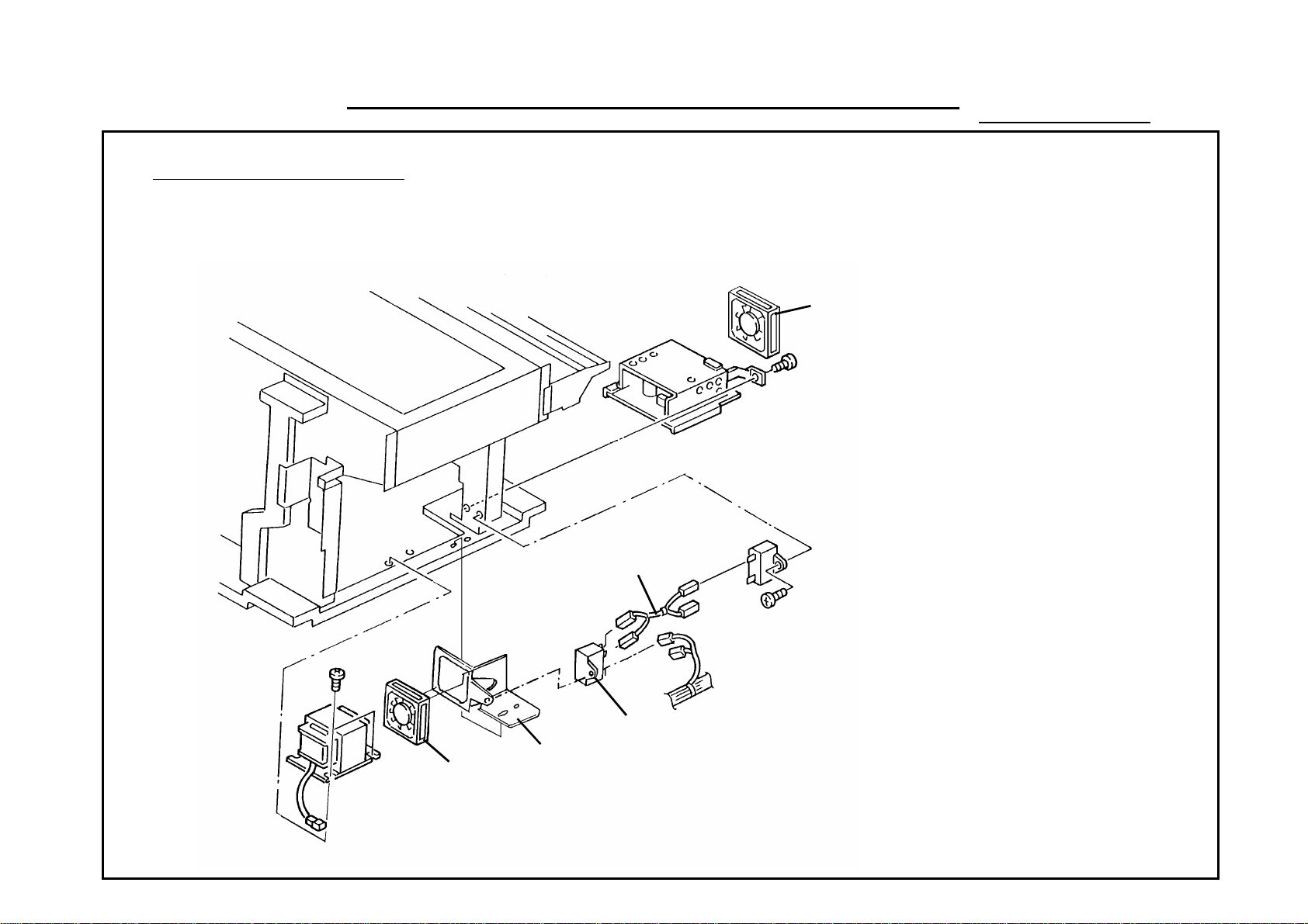
Page 50

MODIFICATION BULLETIN NO. 24 PAGE 1 OF 2
44
ISSUED ON: July 15, ’94
Model SP40 Volt/Hz
Modified Article Parts Catalog
Reason for
Parts Catalog Correction
Modification
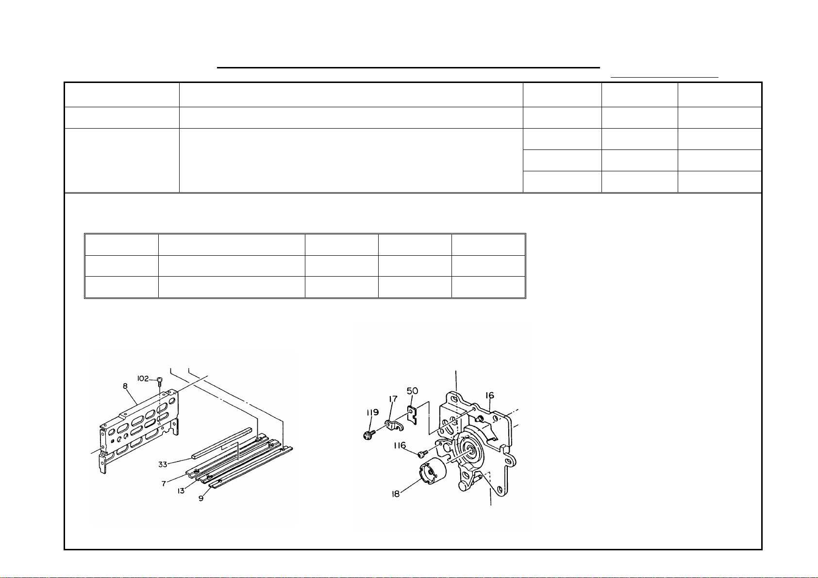
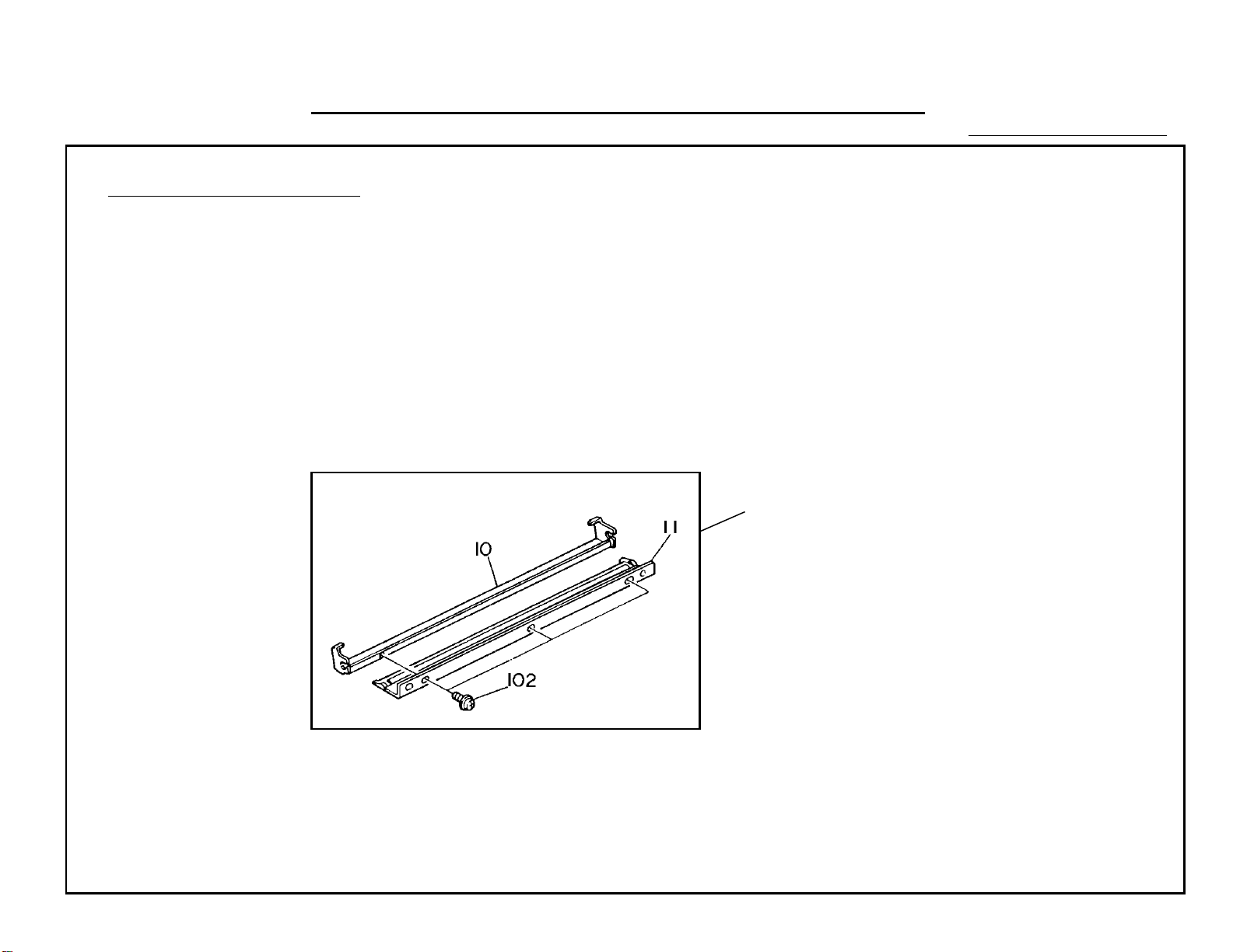
Please collect the illustration of page 34 as shown below.
44 40
39
42
41
Date of
Modification
Serial Number
48
102
S. Hamano, Assistant General Manager
Technical Support Department
Page 51

MODIFICATION BULLETIN NO. 24 PAGE 2 OF 2
ISSUED ON: July 15, ’94
MODEL NAME
Savin 9040 i 115/60 USA Canada A089-15
Ricoh FT400 i 110/60 Taiwan A089-19
Ricoh FT400 i 220/50 Asia, Oceania A089-29
Savin 9050 i 115/60 USA Canada A108-15
Ricoh FT500 i 110/60 Taiwan A108-19
Ricoh FT500 i 220/50 Asia, Oceania A108-29
V/Hz DESTINATION CODE SERIAL NUMBER
Page 52

MODIFICATION BULLETIN NO. 25 PAGE 1 OF 2
ISSUED ON: July 31, ’94
Model SP40 / SP50 Volt/Hz
Modified Article Stud
Reason for
Vender Change
Modification
Due to vender chang e, part numbers of the st ud has be en chan ge d.
Inter-
Old P/N New P/N Description Q’ty Used
AA143045 54032819 Stud
1 → 1
change-
ability
O/O
Date of
Modification
Parts Catalog
Index No. Page
54
16
35
39
Serial Number
S. Hamano, Assistant General Manager
Technical Support Department
Page 53

MODIFICATION BULLETIN NO. 25 PAGE 2 OF 2
ISSUED ON: July 31, ’94
MODEL NAME
Savin 9040 i 115/60 USA Canada A089-15
Ricoh FT400 i 110/60 Taiwan A089-19
Ricoh FT400 i 220/50 Asia, Oceania A089-29
Savin 9050 i 115/60 USA Canada A108-15
Ricoh FT500 i 110/60 Taiwan A108-19
Ricoh FT500 i 220/50 Asia, Oceania A108-29
V/Hz DESTINATION CODE SERIAL NUMBER
Page 54

MODIFICATION BULLETIN NO. 26 PAGE 1 OF 2
ISSUED ON: July 31, ’94
Model SP40/50 (SP40 Only) Volt/Hz
Modified Article Main Board ROM
Reason for
To erase white line in the half tone area
Modification
Parts Catalog
Old P/N New P/N Description
Index No. Page
A0895129 A0895128 IC - AM27C512 - 155DC 2 49
Date of
Modification
It was reported that a few thousa nd copies after installation, vertical white lines start to appear on the cop ies. This
especially happens in the half tone are a of the 1st cop y. This problem is caused by toner particles accu mula ting on the
cleaning blade edge during the cop y run. To minimize the vertical white lines on the 1st copy, the transp ort and main
change timings have been changed.
Serial Number
S. Hamano, Assistant General Manager
Technical Support Department
Page 55

MODIFICATION BULLETIN NO. 26 PAGE 2 OF 2
ISSUED ON: July 31, ’94
MODEL NAME
Savin 9040 i 115/60 USA Canada A089-15
Ricoh FT400 i 110/60 Taiwan A089-19 A3273040001
Ricoh FT400 i 220/50 Asia, Oceania A089-29 A327310001
Savin 9050 i 115/60 USA Canada A108-15
Ricoh FT500 i 110/60 Taiwan A108-19
Ricoh FT500 i 220/50 Asia, Oceania A108-29
V/Hz DESTINATION CODE SERIAL NUMBER
Page 56

MODIFICATION BULLETIN NO. 27 PAGE 1 OF 2
ISSUED ON: July 31, ’94
Model SP40/50 (SP50 Only) Volt/Hz
Modified Article Main Board ROM
Reason for
To minimize paper separation jams
Modification
Parts Catalog
Old P/N New P/N Description
Index No. Page
A1085129 A1085127 IC - AM27C512 - 150DC 2 49
Date of
Modification
It was reported that separa tio n jams (03) are sometimes detected when options (sorter, ADF, duplex unit) are
installed on the SP50. This is becau se sensor on timing in the software is delayed from the actual sensor on time
when an option is installed. If the sen sor on timing in the software is later than the jam det ect ion timing , a pa per ja m
is detected. The occurrence ratio is highe r if more op tio ns are installed.
To counter this, the jam detection timing in the software has been changed.
Serial Number
S. Hamano, Assistant General Manager
Technical Support Department
Page 57

MODIFICATION BULLETIN NO. 27 PAGE 2 OF 2
ISSUED ON: July 31, ’94
MODEL NAME
Savin 9040 i 115/60 USA Canada A089-15
Ricoh FT400 i 110/60 Taiwan A089-19
Ricoh FT400 i 220/50 Asia, Oceania A089-29
Savin 9050 i 115/60 USA Canada A108-15 1931100001
Ricoh FT500 i 110/60 Taiwan A108-19 A333401XXXX
Ricoh FT500 i 220/50 Asia, Oceania A108-29 A3333120001
V/Hz DESTINATION CODE SERIAL NUMBER
Page 58

MODIFICATION BULLETIN NO. 28 PAGE 1 OF 3
ISSUED ON: July 31, ’94
Model SP40 / 50 Volt/Hz
Modified Article Decal - Fusing Cover
Reason for
To ensure correct operation by customers
Modification
Draw
No.
Old Parts
No.
AA001239 AA001284 Decal - Fusing Cover
New Parts
No.
Description Rank
Q’ty Used
Old→→New
1 → 1
Date of
Modification
Inter-
change-
ability
X/O 24 35
Parts needed for replacement by new part
Part No. Description No. Page
Serial
Number
Parts
Catalog
Rank: A : Replace with new parts immediately. B : Replace with new parts at time of repair. C : Replace with new parts at time of overhaul.
Interchangeability:
(1) When old and new parts are not mutually interchangeable, use additional parts or an assembly part as indicated in "Parts needed for
replacement by new part" to install the new part.
(2) The mark to the left of the slash indicates whether the old part can be used in the new machine, and the mark to the right indicates whether
the new part can be used in the old machine. x = Not interchangeable o = Interchangeable
Page 59

MODIFICATION BULLETIN NO. 28 PAGE 2 OF 3
ISSUED ON: July 31, ’94
DETAILS OF MODIFICATION
When the fusing unit is pulle d ou t, the Fusing Cover [A] should be handled.
If a customer pulls out the fusing unit by handling th e oil ta nk [B], the tank position would move out of its normal
position causing oil lea kag e.
To ensure correct operatio n, the Decal - Fusing Cover ha s bee n cha nged .
[B]
[A]
S. Hamano, Assistant General Manager
Technical Support Department
Page 60

MODIFICATION BULLETIN NO. 28 PAGE 3 OF 3
ISSUED ON: July 31, ’93
MODEL NAME
Savin 9040 i 115/60 USA Canada A089-15 394020001
Ricoh FT400 i 110/60 Taiwan A089-19 A327403XXXX
Ricoh FT400 i 220/50 Asia, Oceania A089-29 A327403XXXX
Savin 9050 i 115/60 USA Canada A108-15 1940200001
Ricoh FT500 i 110/60 Taiwan A108-19 A333403XXXX
Ricoh FT500 i 220/50 Asia, Oceania A108-29 A333403XXXX
V/Hz DESTINATION CODE SERIAL NUMBER
Page 61

MODIFICATION BULLETIN NO. 29 PAGE 1 OF 2
ISSUED ON: January 15, ’95
Model SP40 / SP50 Volt/Hz
Modified Article Fusing Unit Oil Sump
Reason for
To prevent oil leakage
Modification
Date of
Modification
To prevent oil leakage fro m t he oil b lad e an d th e oil sump when paper sludge accumulat es on the oil blad e / oil
sump, guide plates and end fence have been added to the oil sump as sho wn in the illustration. The sup port
bracket has also been changed to mat ch the new style oil sump.
Old P/N New P/N Description Q’ty Used
A0304118 A0894104 Oil Sump
A0894113 A0894114 Oil supply Support Bracket
1 → 1
2 → 2
Inter-
change-
ability
X/O 28 37
X/O 31 37
Parts Catalog
Index No. Page
Support Bracket
Serial Number
Old Style
Guide Plate
Fence
New Style
S. Hamano, Assistant General Manager
Technical Support Departme nt
Page 62

MODIFICATION BULLETIN NO. 29 PAGE 2 OF 2
ISSUED ON: January 15, ’95
MODEL NAME
Savin 9040 i 115/60 USA Canada A089-15 3940800001
Ricoh FT400 i 110/60 Taiwan A089-19 3930900001
Ricoh FT400 i 220/50 Asia, Oceania A089-29 A3273090001
Savin 9050 i 115/60 USA Canada A108-15 194080001
Ricoh FT500 i 110/60 Taiwan A108-19 A333412XXXX
Ricoh FT500 i 220/50 Asia, Oceania A108-29 A3334080008
V/Hz DESTINATION CODE SERIAL NUMBER
Page 63

MODIFICATION BULLETIN NO. 30 PAGE 1 OF 1
ISSUED ON: October 31, ’95
Model SP40 / 50 Volt/Hz
Modified Article Parts Catalog No serial number cut-in information
Reason for
Parts Catalog Correction
Modification
Date of
Modification
Serial Number
Please correct your parts catalog as follows:
Incorrect P/N Correct P/N Incorrect Description Correct Description
Index No. Page
A0894145 A0894140 Fusing Unit Left Rail Entrance Guide Plate 26 37
A0894140 A0894145 Entrance Guide Plate Fusing Unit Left Rail 33 37
Parts Catalog
A0894140
Entrance Guide Plate
A0894145
Fusing Unit Left Rail
M. Iwasa, Manager
Technical Support Department
Page 64

MODIFICATION BULLETIN NO. 30 PAGE 1 OF 1
ISSUED ON: November 15, ’95
Model SP40 / 50 Volt/Hz
Modified Article Power Relay DC 24V No serial number cut-in information
Reason for
Vender change
Modification
Inter-
Old P/N New P/N Description Q’ty Used
12081081 12081394 Power Relay - DC24V
1 → 1
change-
ability
O/O 115 43
Index No. Page
Date of
Modification
Parts Catalog
Serial Number
M. Iwasa, Manager
Technical Support Department
Page 65

MODIFICATION BULLETIN NO. 32 PAGE 1 OF 1
ISSUED ON: December 31, ’95
Model SP40 / 50 Volt/Hz
Modified Article
Reason for
Modification
Old P/N New P/N Description Q’ty Used
1407 2057 IC - 82C55AFP - 5
1407 2058
ICs
Vender change
1407 3336 IC - TMP82C55AM - 10
IC - 82C54FP - 6
1407 3756 TIMER - TMP82C54M - 2
Inter-
change-
ability
1 → 0
O/O 136 49
0 → 1
1 → 0
O/O 137 49
0 → 1
Date of
Modification
No serial number cut-in information
Parts Catalog
Index No. Page
Serial Number
M. Iwasa, Manager
Technical Support Department
 Loading...