

Page 1
Technica l Bulletin No . RTB-00 1
SUBJECT: SC54 and SC55 (220/230/ 240V machines only) DATE: Dec . 15, ’ 92
PAGE: 1 o f 2
PREPARED BY: M. Fur us awa
CHECKED BY: T. Ito
CLASSIFICATION:
Action Required
Troubleshooting
Retrofit Information
Phenomenon:
SC55 (Fusing overheat) occurs during the operation. This condition may be reset by
entering to the SP mo de. However, the interval to the next SC55 becomes shorter and
shorter and finally it can’t be reset. SC54 (Fusing warm-up error) may occur instead of
SC55 under the same condition. This is a very rare problem but it may occur during
installation or soo n after installation.
This p ro blem happ ens on ly on th e 220/230/ 240V mach ines b ecau se o f its inp ut voltag e.
This problem has not been reported on the N440 series but only on the A7 series.
Since th e 220/230/240V ver sio n of t he N440 series uses t he same d c po wer s upp ly
board, the possibility of this problem for the N440 series should be the same.
Possible ca use:
The surge current to the fusing triac (TRC402) of the dc power supply board when the
main switch is turned on might cause the triac to deteriorate little by little. This depends
on co nd itio ns suc h as in pu t vo ltag e fluc tuat ion and co mb inat ion of var iou s elect ric al
component’s torelance. When the deterioration of the triac reaches a certain level, the
triac will start conducting half waves. The CPU c annot contr ol the fusing temperature
und er t his c on dit ion , c ausin g SC55 o r SC54.
The sequence of the electrical component (main switch, power relay, and fusing triac)
ON timing when the main switch is turned on may result in a large surge current to the
fusing triac.
Revision of service manual
Information only
Other
FROM: Copier Technical Support Section
MODEL:
N440 Series
(A085/A087/ A088)
Action in the fie ld:
The fo llow ing actio n is req uir ed in the field :
Chang e t he set ting o f SP29 (Fusing temp er atur e c on tro l m od e) fro m "0" (ON/ OFF
contro l) to "1" (Phase control) at the next visit to customers or at machine installation.
NOTE: Please co rrec t the exp lanat ion o f SP29 in your ser vice m anual ( Page 4-5). Data "0"
is not for "Zero-cross control" but for "ON/OFF control".
[E xplanation]
Phase control mode will not give any chance of a large surge current to the fusing triac
as the sequence of the electrical component ON timing is different from that in ON/OFF
control mode. Therefore, once the fusing control is changed to Phase control mode, the
fusin g t riac will never det erio rat e.
This c op ier c o ntr o ls th e fusin g temp er atur e in ON/ OFF co nt ro l mo d e as a s tand ard .
However, it can be changed to Phase control mode in case electric lights go darker
briefly when the fusing lamp kicks in under poor electric power supply conditions.
Page 2

Technica l Bulletin No . RTB-00 1
SUBJECT: SC54 and SC55 (220/230/ 240V machines only) DATE: Dec . 15, ’ 92
PAGE: 2 o f 2
On the other hand, it won’t give any trouble in Phase control mode under normal
conditions, but some electrical equipment might have a little electrical noise if it is
connected to the same wall outlet with the copier.
Considering the difference between the two control modes, Ricoh has decided to use
the Phase control mod e as a countermeasure for the machines in fields.
Permanent countermeasure:
The software of the main ROM will be modified to correct the sequence of the electrical
co mp o n ent ON tim ing . This will allo w th e alter nat ive selec tio n o f either ON /OFF o r
Phase control mode in the field as intended in the machine design.
The part numbers of the main ROM and the main control board will be changed
through this mod ification.
The new part numbers and the cut-in serial numbers will be informed later by a
Modification Bulletin.
Page 3
Technica l Bulletin No . RTB-00 2
SUBJECT: Tray Heater Location (Duplex Machine: A088 Only) DATE: Feb . 15, ’ 9 3
PAGE: 1 o f 1
PREPARED BY: M . Fu ru saw a
CHECKED BY: T. Ito
CLASSIFICATION:
Action Required
Troubleshooting
Retrofit Information
The following problem was reported on A7 series from the Japanese domestic market.
Since the layout of N440 series is the same as that of A7 series, the same action is
required.
[PROBLEM]
The duplex tray cannot be pulled out because the tray bottom part has been deformed
due to heat. Several cases were reported with machines which were not used over one
week du e to ho liday s.
[CAUSE]
Revision of service manual
Information only
Other
FROM: Copier Technical Support Section
MODEL:
N440 Series
(A085/A087/A088)
The g ap b etw een t he tr ay h eater b rac k et an d t he d u plex tr ay b o tt om par t is 7.6 m m, w hile
that bet ween t he t ray h eater b rac ket and t he p aper tr ay b o tto m p art is 20.2 m m.
Since this gap on duplex machines is not wide enough, the duplex bottom part may be
defo rm ed d ue t o h eat fr om th e tr ay h eater w hen the m ac hines are n ot us ed ( wit h th e
power cord plugged in) for a long period. When the deformation of the duplex tray bottom
part becomes too great, the duplex tray may not be pulled out.
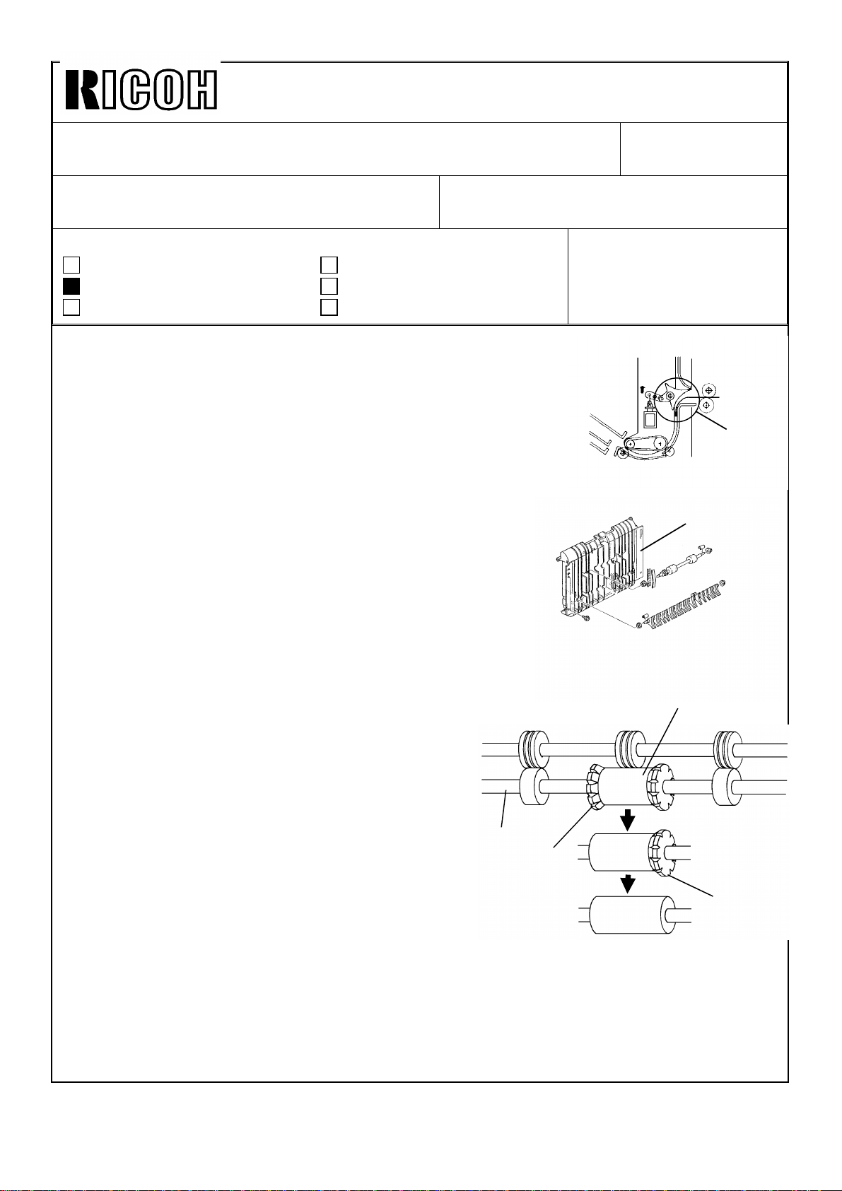
[ACTION IN THE FIELD]
Refer to 2. 5 TRAY H EATER INSTALLATION (Page 3-21) in t he A7 ser vice m anu al.
The fo llowin g ac tio n is req uired fo r th e duplex machines (A088):
•• For areas with not so high hum idity, disconnect the upper tray heater
at the next PM call.
•• For areas with high humidity, change the location of the tray heater
from the upper tray to the lower tray at the next PM c all.
[PERM ANENT COUN TERM EASURE]
Prod uc tio n mac hin es will have a new heater on the 6th mirro r b rac k et and the u pp er tr ay
heat er will b e elimin ated . Details and th e cut -in s erial nu mb ers will be in for med b y a
Modification Bulletin later.
Page 4
Technica l Bulletin No . RTB-00 3
[Figure 3]
Sup er
Glue
NG
OK
SUBJECT: Toner Cartridge not Set Correctly DATE: Feb . 15, ’ 9 3
PAGE: 1 o f 1
PREPARED BY: M . Fu ru saw a
CHECKED BY: T. Ito
CLASSIFICATION:
Action Required
Troubleshooting
Retrofit Information
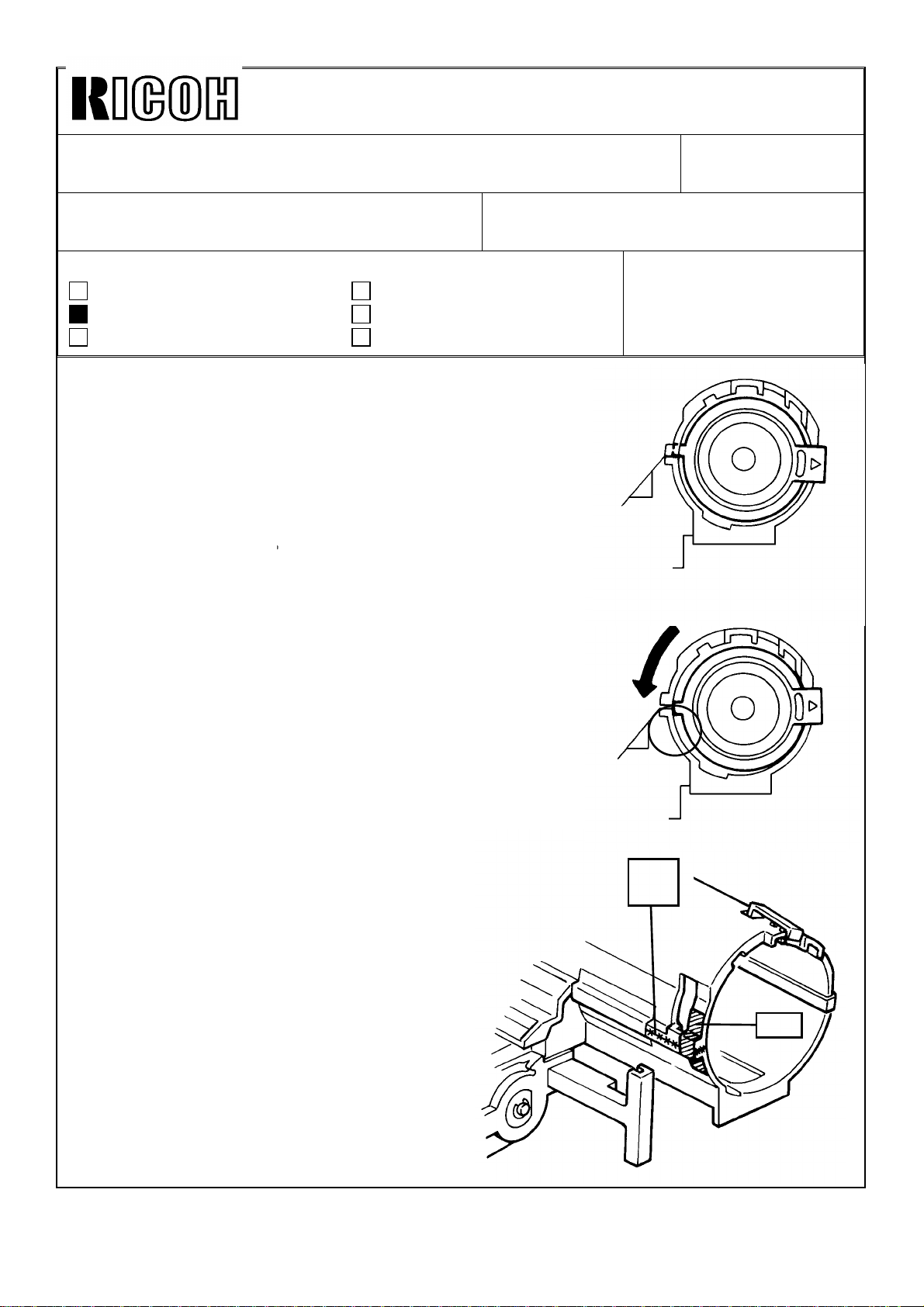
[PROBLEM]
When a toner cartridge is set in the wrong position as
shown in figure 2, the "Add Toner" indicator comes on
again.
[CAUSE]
When a toner cartridge is forced to turn or when it is turned
by being pressed to the right side, the upper and lower
casin gs will b e warp ed and m ake a gap at the fr on t left
side. Then the cartridge stops at the overturned position as
shown. Under this condition, the toner supply opening of
the toner cartridge does not match the toner supply roller
opening, causing toner not to be supplied.
Revision of service manual
Information only
Other
FROM: Copier Technical Support Section
MODEL:
N440 Series
(A085/A087/A088)
[Figure 1]
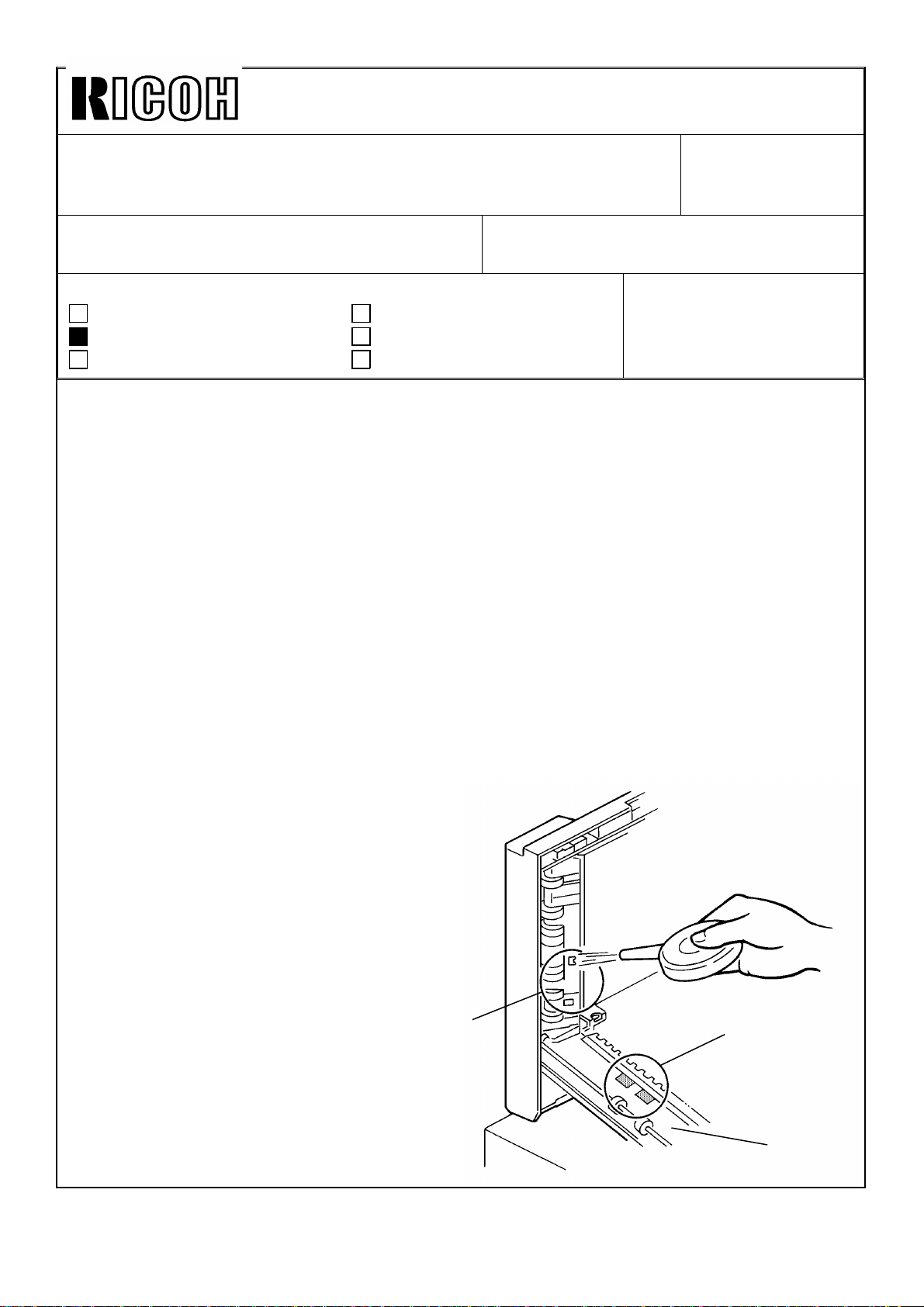
[ACTION IN THE FIELD]
1. Remove the toner cartridge from the toner supply unit.
2. Clean t he up per and lower casin gs at the fr on t left sid e
with a dry cloth, then adhere the upper and lower
casings with super glue as shown in figure 3.
3. Since it may take twenty to thirty minutes
for the super glue to dry, stick a strip of
tape on the toner supply unit casing as
shown.
4. Reinstall the toner cartridge.
[PERM ANENT COUN TERM EASURE]
The lower casing will be modified to ensure
a proper stop position of the toner
cartridge, and a strip of tape (matching this
field action) will be stuck at the factory.
Details a nd cu t-in seria l num ber s w ill be
sent later by a Modification Bulletin.
[Figure 2]
Tape
Page 5
Technica l Bulletin No . RTB-00 4
[A]
SUBJECT: Rubber Feet on Copier Base Plate DATE:Mar. 15, ’ 93
PAGE: 1 o f 1
PREPARED BY: M . Fu ru saw a
CHECKED BY: T. Ito
CLASSIFICATION:
Action Required
Troubleshooting
Retrofit Information
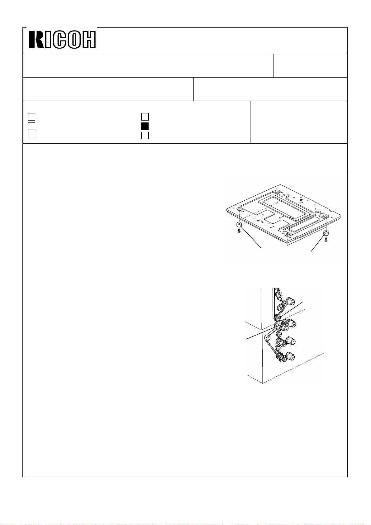
Please be informed that the molding feet [A] have been used on the copier base plate
from the first mass-production as the following problem
was found on the A7 series:
When the copier is installed on the paper tray unit, the
rub ber feet are c om pr essed by the c op ier’ s weig ht an d
they may be shortened.
When this occurs the gear mesh between the tray unit
drive and driven gears [B,C] b ecomes tight, causing
noise.
To p revent this, t he mat erial of t he feet has b een
changed to a hard one on the A7 series. This
mo dificat ion has also been app lied to the N440 s eries
from the first mass-production.
Revision of service manual
Information only
Other
FROM: Copier Technical Support Section
MODEL:
N440 Series
(A085/A087/A088)
[A]
As the height of the N440 copier is above that of other
cop iers, the copier will be installed on the paper tray
unit or its unique table normally, in order to operate the
co pier easily.
However, in case that the copier is installed on a
normal commercial table, please note that the copier
may slip on the table rather easily with the molding feet.
If the c o p ier slip s eas ily o n t he t able, it is ad vised t o
stick rubber plates on the feet by glue or two sided
tape for safety. You can use a commercial rubber plate
and cut it for the feet .
[B]
[C]
Page 6
Technica l Bulletin No . RTB-00 5
[B]
[E]
SUBJECT: Sorter Stapler "MATT20" (A374)
Pape r J ams in T urn Gate Se ction
PREPARED BY: M . Fu ru saw a
CHECKED BY: T. Ito
CLASSIFICATION:
Action Required
Troubleshooting
Retrofit Information
[PHENOMENON]
Paper jams occur in the turn gate section [A] intermittently in
sort, stack, or staple mode.
[PO SSIBLE CAUSE]
The so rt er ad ap ter lo wer exit ro ller [B] h as a s tiffnes s inc reas ing
roller [ C] at the middle. This rubber roller has a flange on
each end. The flanges produce slight waves on copy
paper perpendicular to the paper transport direction to
increase paper stiffness.
The rear side wave position may not be proper for one of
the ribs on the sorter stapler vertical paper guide [D]
especially when paper has excessive face curl. The rib
may make a mark on the paper lead edge or may cause
paper jams.
Revision of service manual
Information only
Other
FROM: Copier Technical Support Section
DATE: Mar. 15, ’93
PAGE: 1 o f 1
MODEL:
N440 Series
(A085/A087/A088)
[A]
[D]
[ACTION IN THE FIELD]
1. Cut off the rear flange [E] with cutting pliers and smo oth
the r olle r’ s ed ge with a knife. This will elim inat e
the rear side wave on paper.
(As the flanges have wedge grooves originally
and the roller is turning in forwarding direction,
the r olle r sur fac e do es n ot have to b e co mp let ely
smooth after you cut off the flange.)
2. If step 1 does not cure the problem, cut off the
fro nt flang e [F] as well.
(Paper transport reliability without flanges on the
roller was tested for thin paper under high
hum id ity c o nd itio n, resu lting in no p r ob lem .)
[PERM ANENT COUN TERM EASURE]
The width of the rib on the sorter stapler vertical paper guide will be increased to improve
the paper transport ability. The part number of the vertical paper guide will remain as it is.
This mo d ificatio n will b e app lied t o t he p ro du ctio n m ach ines fr om April, 1993.
[C]
[F]
Page 7
Technica l Bulletin No . RTB-00 6
SUBJECT: ARDF Origin al misfe ed. DATE:
Mar. 15, 1993
PAGE: 1 o f 2
PREPARED BY: N . Tak ai/ M. Fur us awa
CHECKED BY:
CLASSIFICATION:
Action Required
Troubleshooting
Retrofit Information
Revision of service manual
Information only
Other
FROM: Copier Technical Support Section
MODEL:
N440 Series
(A085/A087/ A088)
Symptom:
Original misfeed occ urs intermittently.
Possible Ca use:
1. The DF registration sensor is activated by paper dust on the sensor pad, affecting its
color.
2. When t he o rig inal feed ro ller star ts r ot ating , t he DF up pe r g uid e plat e is war ped slig ht ly
downward. The clearance between the DF registration sensor and the sensor pad is
reduced. When this happens, the DF registration sensor (reflective type) can receive the
reflective light from the sensor pad, even though its color is black.
Action Required:
(For cause 1)
1. Op en th e feed -in un it [A] .
2. Clean t he DF regist ratio n s enso r
surface [B] and the sensor pad [C].
NOTE: To remove the paper dust from
the sensor pad, it is better to
use scotch tape.
[B]
[C]
[A]
Page 8
Technica l Bulletin No . RTB-00 6
SUBJECT: ARDF Origin al misfe ed. DATE:
Mar. 15, 1993
PAGE: 2 o f 2
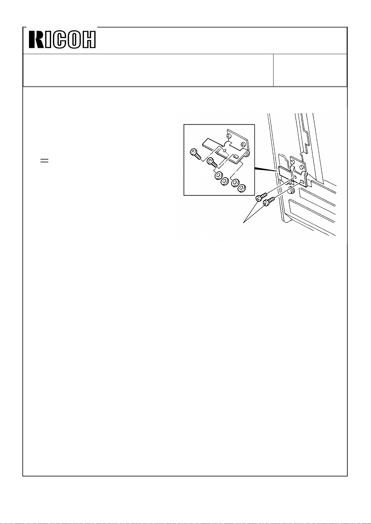
(For cause 2)
1. Remove the two screws of the pull out
hinge [D].
2. Ins ert 2 pc s eac h of 0. 8 mm sp ac er
(P/No . 07010040) and fix th e sc rew s.
[E].
•
This c an g ive the reg ist ratio n s enso r
enough clearance for the sensor pad.
[E]
[D]
Perma nent Counterme asure :
The shap e of t he pu ll ou t br ack et (P/N o. A4651057) will be mo d ified so that the sen sor
pad is positioned 1.5 mm further from the DF registration sensor.
Soon after the modification is applied to the prod uction, an M/B will be issued.
Page 9
Technical Bulletin No. RTB-007
SUBJECT: SC54 and SC55 (220/230/240V machines only)
Additional information
PREPARED BY: M. Furusawa
CHECKED BY: T. Ito
CLASSIFICATION:
Action Required
Troubleshooting
Retrofit Information
Refer to the RTB No.001 for the phenomenon, possible cause, and action in the field
concerning the above subject.
The following is additional information for the permanent countermeasure:
As it is mentioned in the RTB No.001, the software of the main ROM has been modified to
correct the sequence of the electrical component (main switch, power relay, and fusing
triac) ON timing.
The part numbers of the main ROM and the main control board have been changed as
follows (Refer to the M/B No.11 for the cut-in serial numbers.):
Main ROM: (Old) A0855114 (New) A0855154
Main Control Board:(Old) A0855111 (New) A0855151
Revision of service manual
Information only
Other
FROM: Copier Technical Support Section
MODEL: N440 Series
(A085/A087/A088)
Double underlined part
has been revised.
REISSUED
ON: June 15, ’93
DATE: May 15, ’93
PAGE: 1 of 1
The software of the I/O ROM (IC132) soldered on the main control board has also been
modified in addition to the above modification (Refer to the M/B No.14 for the cut-in serial
numbers.):
I/O ROM: (Old) A0855118 (New) A0855158
Main Control Board:(Old) A0855151 (New) A0855171
[Explanation]
With the modified main ROM, the copier can operate in ON/OFF control mode without
deteriorating the fusing triac (TRC402) under normal usage conditions.
However, the fusing triac might deteriorate gradually when the following three steps
occur together although the possibilities of this occurring are very low:
1. The main switch is ON.
2. The front door is open.
3. Then the front door is closed when the fusing temperature becomes low (nearly
room temperature).
To eliminate this possibility, the software of the I/O ROM has been modified as the
second countermeasure.
The countermeasures have been applied in two steps as mentioned above because the
modification of the masked type I/O ROM took time.
In case of the machines with only the first countermeasure, the modified main ROM, the
above possibility occurring can be eliminated by setting the data of SP29 (Fusing
temperature control mode) at "1" (phase control) without changing the I/O ROM.
Page 10
Technical Bulletin No. RTB-008
SUBJECT: Sorter Stapler (Matt20)
Bin Lift Wire Installation Procedure
PREPARED BY: M. Furusawa
CHECKED BY: T. Ito
CLASSIFICATION:
Action Required
Troubleshooting
Retrofit Information
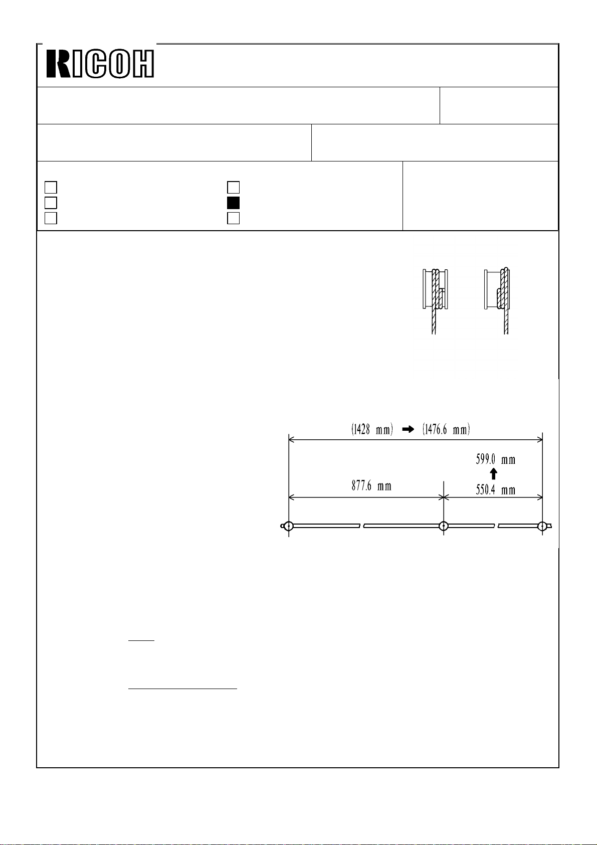
The bin lift wire may loosen on the wire pulley during
transportation. When the wire pulley is driven from the
home position under this condition, the wire may be
wound up wrongly as shown in the figure 1. This will
change the bin stop positions, resulting in paper jams.
To eliminate this possibility, the bin lift wire has been
lengthened as shown in the figure 2. This will give another
half turn of the lift wire on the pulley to prevent the wire
from being wound up wrongly.
Revision of service manual
Information only
Other
FROM: Copier Technical Support Section
DATE: July 31, ’93
PAGE: 1 of 2
MODEL:
N440 Series
(A085/A087/A088)
OK
[Figure 1]
NG
Refer to the Modification Bulletin No. 7
(Model: Sorter stapler for A7/N440) for
the cut-in serial numbers.
With this modification, the wire
installation procedure should be altered
as follows when replacing the wire with
the new type.
Service Manual:
SORTER STAPLER (A374)
15. REPLACEMENT AND
ADJUSTMENT
15.4 BIN LIFT WIRE REPLACEMENT
15.4.2 Wire Installation (Page 46)
Step 3
For the old type:
Wind the wire once as shown and ---Refer to the figures 3 and 5 in the next page.
For the new type:
Wind the wire one and a half turns as shown and -----Refer to the figures 4 and 6 in the next page.
[Figure 2]
NOTE: When replacing either of front and rear wires with the new type, the wire
installation procedure should be a combination of those for the old and new types.
It won’t give any problem.
Page 11

Technical Bulletin No. RTB-008
SUBJECT: Sorter Stapler (Matt20)
Bin Lift Wire Installation Procedure
FRONT SIDE:
= Old type =
[Figure 3]
DATE: July 31, ’93
PAGE: 2 of 2
= New type =
[Figure 4]
REAR SIDE:
= Old type =
[Figure 5]
= New type =
[Figure 6]
Page 12

Technical Bulletin No. RTB-009
SUBJECT: Paper Jam at Sorter Stapler (Matt20) Entrance DATE: Sep. 30, ’93
PAGE: 1 of 2
PREPARED BY: M. Furusawa
CHECKED BY: T. Ito
CLASSIFICATION:
Action Required
Troubleshooting
Retrofit Information
[Symptom]
On the N440 + Matt20 system, the copier CPU sometimes does not recognize the Matt20
when the main switch is turned on. Under this condition, the "C5" code is not displayed on
the operation panel even if the sorter unit or the sorter front cover is opened. When copies
are made, paper jams will occur between the sorter adapter and the sorter entrance as the
sorter roller drive motor does not rotate. Even when this happens, no jam indication is
displayed since the copier is operating without recognizing the Matt20.
This problem may occur on some machines. According to information from the field,
copiers with main control board A0855111G or A0855151 might have this problem, but not
all copiers with them. On the machines with this problem, the symptom is observed for
approximately 50% times when the main switch is turned off and on.
When the menu sheet reader is installed, this problem disappears.
Revision of service manual
Information only
Other
FROM: Copier Technical Support Section
MODEL:
N440 Series
(A085/A087/A088)
[Cause]
When the main switch is turned on, the communication IC (MB89371) on the optional
interface (I/F) board does not reset, resulting in a communication error with the Matt20.
When the menu sheet reader is not equipped, the reset circuit of the main control board
for the communication IC will include an open circuit through the I/F board. Under this
condition electrical noise might affect the reset circuit, causing a reset error to the
communication IC.
[Countermeasure in the field]
Install a jumper connector (P/N: A0889500) on the
CN702 (the connector for the menu sheet reader) of
the I/F board which makes a short circuit between
CN702-1 and CN702-4 with 2.2k ohms resistor.
This connector has the same effect as when the menu
sheet reader is equipped, eliminating the problem.
[Permanent countermeasure]
The I/F board circuit has been modified from August
1993.
A0889500
Page 13

Technical Bulletin No. RTB-009
SUBJECT: Paper Jam at Sorter Stapler (Matt20) Entrance DATE: Sep. 30, ’93
PAGE: 2 of 2
[Other information]
This problem won’t occur on the A7 + Matt20 system as the reset circuit pattern of the
main control board for the communication I/C is independent from the menu sheet reader
circuit.
It won’t cause any problem if the jumper connector is installed on a new I/F board or on
the A7 system by mistake.
Neither the software of the copier main ROM nor the main control board have any relation
to this problem. But the type and manufacturer of the main ROM might affect the
occurrence ratio of this problem.
The following are our test results:
Manufacturer Type
AMD am27c010-150DC 21/30
AMD am27c010-155DC 0/30
Hitachi HN27c101AG-17 0/30
SGS M27c1001- 12FI 0/30
Occurrence
Ratio
Page 14

Technical Bulletin No. RTB-010
SUBJECT: Sorter Stapler (Matt20)
Paper Exit Jam
PREPARED BY: J. Mochizuki
CHECKED BY:
CLASSIFICATION:
Action Required
Troubleshooting
Retrofit Information
In page 2 of 2, the following comment is newly added by this re-issued RTB.
We recommend to do this lubrication at every PM.
EM 120K 240K 360K NOTE
Bushings and exit
rollers
Revision of service manual
Information only
Other
LLL
FROM: 2nd Technical Support Section
MODEL:
N440 Seri es
(A085/A087/A088)
Use Launa oil
DATE:Mar.15,’94
PAGE: 1 of 1
Page 15

Technical Bulletin No. RTB-010
SUBJECT: Sorter Stapler (Matt20)
Paper Exit Jam
PREPARED BY: J. Mochizuki
CHECKED BY:
CLASSIFICATION:
Action Required
Troubleshooting
Retrofit Information
FROM: 2nd Technical Support Section
Revision of service manual
Information only
Other
MODEL:
N440 Seri es
(A085/A087/A088)
DATE: Feb.15,’94
PAGE: 1 of 2
Symptom:
In Sort/Stack mode, when copy paper is fed out to a bin, the roller drive motor speed
becomes higher. The motor occasionally hesitates at that moment, paper exit jam occurs.
Possible Cause:
The load of the roller drive motor is too large. The friction between the shafts and bearings
exceeds the roller drive motor torque.
Action Required:
1. Lubricate the the following parts using launa oil.
1) Between the bushings [A] and shafts
2) Between the exit rollers [B] and the shafts [C]
[B]
[C]
[A]
[A]
Page 16

Technical Bulletin No. RTB-010
SUBJECT: Sorter Stapler (Matt20)
Paper Exit Jam
We recommend to do this lubrication at every PM.
EM 120K 240K 360K NOTE
Bushings and exit
rollers
2. Reduce the timing belt tension.
1) Remove the proof tray.
2) Remove the rear cover.
3) Loosen the screws fixing the roller drive motor [A] bracket.
4) Slightly reduce the timing belt [B] tension, and retighten the screw.
Note: After reducing the belt tension, make A3 size copies in normal mode
to make sure no belt jumping.
LLL
DATE: Feb. 15,’94
PAGE: 2 of 2
Use Launa oil
[B]
[A]
Page 17

Technical Bulletin No. RTB-011
Oct. 31, ’94
SUBJECT: MATT20 (A374) TROUBLESHOOTING GUIDE DATE:
PAGE: 1 of 14
PREPARED BY: F. Noguchi
CHECKED BY: S. Hamano
CLASSIFICATION:
Action Required
Troubleshooting
Retrofit Information
To aid the technician in troubleshooting matt20 misfeeds we are issuing this
troubleshooting guide. If the guide is used properly it will resolve the majority of
misfeeding problems the field is experiencing.
Revision of service manual
Information only
Other
FROM: Copier Technical Support Section
MODEL: N440
TABLE OF CONTENTS SYMPTOM TYPE
1. Roller Drive Motor Stalls and Paper Exit Jams.
2. Sorter Bin Jams or Copies out of order.
3. Incorrect Bin Position and Bin Entrance Jams.
4. Proof Tray Jams with Thick Paper.
5. Sorter Stapler Paper Jams in Turn Gate Section. (RTB - 005)
6. Paper Jam at Sortor Stapler Entrance. (RTB - 009)
7. Turn Gate Area Misfeeds.
Page 18

Technical Bulletin No. RTB- 011
Oct. 31, ’94
SUBJECT: MATT20 (A374) TROUBLESHOOTING GUIDE DATE:
PAGE: 2 of 14
1. ROLLER DRIVE MOTOR STALLS AND PAPER EXIT JAMS
[Symptom]
In Sort/Stack mode, when copy paper is fed out to a bin, the roller drive motor speed
should become higher. The motor occasionally hesitates at that moment and paper exit
jam occurs.
[Possible Cause]
The load of the roller drive motor is excessive when the roller shafts and bushing became
dirty, the friction between the roller shafts and bushings exceeds the roller drive motor
torque.
[Action Required]
Lubricate the drive parts using launa oil. (See page 2 ∼ 4)
NOTE : If the drive parts have not been initially cleaned with alcohol, clean them before
lubricating.
Page 19

Technical Bulletin No. RTB-011
Oct. 31, ’94
SUBJECT: MATT20 (A374) TROUBLESHOOTING GUIDE DATE:
PAGE: 3 of 14
LUBRICATION
[B]
[A]
To reduce the load to the roller drive motor, lubricate as follows at every PM:
1. Open the sorter stapler then disconnect the link lever [A] (1 stepped screw).
2. Disconnect the sorter stapler interface harnesses and a grounding wire (1 screw).
3. Remove the sorter stapler from the mounting frame.
4. Remove the proof tray [B] (1 screw).
5. Remove the rear covers [C] (6 screws).
[C]
Page 20

Technical Bulletin No. RTB-011
Oct. 31, ’94
SUBJECT: MATT20 (A374) TROUBLESHOOTING GUIDE DATE:
PAGE: 4 of 14
[A]
[A]
[D]
Exit Roller
[C]
[D]
[C]
Old
[B]
6. Lubricate the bushings [A] with launa oil.
NOTE: Lubricate the bushings from the both sides so that the oil is fully supplied between
the shaft and the bushing.
7. Gently push down the support bin [B] then lubricate the exit rollers [C] with launa oil.
NOTE: 1. Lubricate the inner side of the brackets [D] so that launa oil is fully supplied
between the shaft and the roller.
2. When the exit rollers [C] are replaced with new ones (P/N A3742541), no
lubrication at every PM will be required.
This is because the new exit roller contains oil in the bushing.
New
Page 21

Technical Bulletin No. RTB-011
Oct. 31, ’94
[B]
SUBJECT: MATT20 (A374) TROUBLESHOOTING GUIDE DATE:
PAGE: 5 of 14
[A]
[A]
[D]
[C]
[E]
[B]
8. Lubricate the bushings [A] with launa oil.
NOTE: Lubricate the bushings from the both sides so that the oil is fully supplied between
the shaft and the bushing.
9. Lubricate the bushings [B] and gear pulley [C] with launa oil.
NOTE: Place a sheet of paper underneath the bushing so that the oil does not drop on
the guide plate.
Wipe off excess oil so that launa oil does not drop on the guide plate during
copying.
10. Lubricate the pulse generator disc [D] and idle pulley [E] with launa oil.
Page 22

Technical Bulletin No. RTB-011
Oct. 31, ’94
SUBJECT: MATT20 (A374) TROUBLESHOOTING GUIDE DATE:
PAGE: 6 of 14
2. SORTER BIN JAMS OR COPIES OUT OF ORDER
[Symptom]
The copy’s trailing edge [A] remains on the guide mylar [B]. When the following paper [C]
comes to the bin, it hits the trailing edge of the proceeding paper, resulting in the paper
jam, or incorrect copy order when the following paper goes underneath the proceeding
paper.
[A]
[C]
[B]
[Cause]
The technician bent the lower bin exit roller holder (spring plate) ( P/N : A3742163) [D],
trying to correct the normal paper skew when the paper exits into the bins. This reduces
the paper transport ability causing bin jams.
[D]
Page 23

Technical Bulletin No. RTB-011
Oct. 31, ’94
SUBJECT: MATT20 (A374) TROUBLESHOOTING GUIDE DATE:
PAGE: 7 of 14
• Supplemental Technical Explanation about the way how paper is
stacked in the bin.
When the copy paper comes out of the sorter, it is angled. This is normal for proper
stacking of the copy paper.
[Mechanism of Paper Stacking]
1. As shown in the illustration, the front side of paper [A] comes out of the sorter first.
NOTE: In order to angle the paper, the diameter of the front and rear transport rollers [B]
are slightly different (front roller: 20.0mm [a], rear roller : 19.7mm [b]).
2. After the entire sheet comes out of the sorter, the paper slides back to the rear fence,
being supported by the gravity for smooth slide.
3. When the corner [C] of the paper contacts the rear fence [D], the paper is still slightly
angled.
4. At this moment, the jogger bar [E] pushes the paper to the front.
5. Because only one corner of the copy paper is touching the rear fence (minimal friction),
the paper can be jogged smoothly.
6. Finally the paper sits squared in the bin because the paper stops being aligned by the
front side frame [F]
[Solution]
Straighten the lower bin exit roller holders so they are flat and ensure that the paper
comes out of the sorter with the correct angle.
NOTE: Once the holders are bent, it may be difficult to completely straighten the holders.
In such a case, replace the entire lower bin exit rollers.
[A]
[C]
[D]
[E]
[a]
[b]
[B]
[F]
Page 24

Technical Bulletin No. RTB-011
Oct. 31, ’94
SUBJECT: MATT20 (A374) TROUBLESHOOTING GUIDE DATE:
PAGE: 8 of 14
3. INCORRECT BIN POSITION AND BIN ENTRANCE JAMS
[Symptom]
The 1st copy hits the support bin causing a bin entrance jam.
[Possible Cause]
Due to gap between the projection [A] of the bin support block [B] and the side frame, the
block can move in the arrow [C] direction. If the block moves away from the bin home
position sensor [D] when the sensor should be actuated, the bin will not stop at the correct
home position. In this case a paper jam occurs at the bin entrance.
[B]
[A]
[D]
[Permanent Countermeasure]
From the march ’93 production, the width of the interrupter [E] for the bin home position
sensor has been increased from 4.5mm to 5.5mm to ensure sensor actuation.
[Countermeasure in the field]
To modify the machines in the field, stick a black mylar strip (5.5mm x 17mm) [F] as
shown in the illustration to expand the width of the sensor actuator.
NOTE: Align the upper and right side edges of the mylar with the sensor actuator.
The part number of the black mylar strip is A3749500 (10pcs / set).
[C]
[E]
4.5mm
[F]
Front view from
paper path
5.5mm
Page 25

Technical Bulletin No. RTB-011
Oct. 31, ’94
SUBJECT: MATT20 (A374) TROUBLESHOOTING GUIDE DATE:
PAGE: 9 of 14
4. PROOF TRAY JAMS WITH THICK PAPER
[Symptom]
When thick paper (like a post card) is used in the proof tray mode, the paper might not be
fed onto the proof tray. The paper stops just before reaching the exit roller [A].
[Cause]
If the paper is face curled, the leading edge of the paper hits the exit roller guide [B] and
the paper does not reach the exit rollers [A].
[Countermeasure]
A hexagon nut (07100050B) [C] has been inserted between the plate spring [D] and the
exit roller guide, so that the angle [θ] between the guide and paper has been reduced. Due
to this modification, the length of the screw [D] fixing the plate spring has been changed
from 6 mm to 8 mm. This modification has been applied from the March ’94 production.
[D]
ϑ
[B]
[A]
[C]
Page 26

Technical Bulletin No. RTB-011
Oct. 31, ’94
SUBJECT: MATT20 (A374) TROUBLESHOOTING GUIDE DATE:
PAGE: 10 of 14
The procedure to apply this modification is as follows:
1. Remove the front and rear covers of the Matt20.
2. Remove the upper cover [A] (2 screws).
3. Remove the two screws [B] fixing the spring plates [C].
4. Insert a hexagon nut (07100050B) between the each plate spring and the exit roller
guide mylar. Fix them using a Philips truss head screw - M4x8 (03440080F).
[A]
[B]
[C]
Page 27

Technical Bulletin No. RTB-011
Oct. 31, ’94
SUBJECT: MATT20 (A374) TROUBLESHOOTING GUIDE DATE:
PAGE: 11 of 14
5. PAPER JAMS IN TURN GATE SECTION (RTB No. - 005)
[PHENOMENON]
Paper jams occur in the turn gate section [A] intermittently in
sort, stack, or staple mode.
[POSSIBLE CAUSE]
The sorter adapter lower exit roller [B] has a stiffness
increasing roller [C] at the middle. This rubber roller has a
flange on each end. The flanges produce slight waves on
copy paper perpendicular to the paper transport direction to
increase paper stiffness.
The rear side wave position may not be proper for one
of the ribs on the sorter stapler vertical paper guide [D]
especially when paper has excessive face curl. The rib
may make a mark on the paper lead edge or may
cause paper jams.
[A]
[D]
[ACTION IN THE FIELD]
1. Cut off the rear flange [E] with cutting pliers and
smooth the roller’s edge with a knife. This will
eliminate the rear side wave on paper.
(As the flanges have wedge grooves originally and
the roller is turning in forwarding direction, the
roller surface does not have to be completely
smooth after you cut off the flange.)
2. If step 1 does not cure the problem, cut off
the front flange [F] as well.
(Paper transport reliability without flanges on
the roller was tested for thin paper under high
humidity condition, resulting in no problem.)
[PERMANENT COUNTERMEASURE]
The width of the rib on the sorter stapler vertical
paper guide will be increased to improve the
paper transport ability. The part number of the vertical paper guide will remain as it is. This
modification will be applied to the production machines from April,1993.
[B]
[E]
[C]
[F]
Page 28

Technical Bulletin No. RTB-011
Oct. 31, ’94
SUBJECT: MATT20 (A374) TROUBLESHOOTING GUIDE DATE:
PAGE: 12 of 14
6. PAPER JAM AT SORTER STAPLER ENTRANCE
(RTB No. - 009)
[Symptom]
On the N440 + Matt20 system, the copier CPU sometimes does not recognize the Matt20
when the main switch is turned on. Under this condition, the "C5" code is not displayed on
the operation panel even if the sorter unit or the sorter front cover is opened. When copies
are made, paper jams will occur between the sorter adapter and the sorter entrance as the
sorter roller drive motor does not rotate. Even when this happens, no jam indication is
displayed since the copier is operating without recognizing the Matt20.
This problem may occur on some machines. According to information from the field,
copiers with main control board A0855111G or A0855151 might have this problem, but not
all copiers with them. On the machines with this problem, the symptom is observed for
approximately 50% times when the main switch is turned off and on.
When the menu sheet reader is installed, this problem disappears.
[Cause]
When the main switch is turned on, the communication IC (MB89371) on the optional
interface (I/F) board does not reset, resulting in a communication error with the Matt20.
When the menu sheet reader is not equipped, the reset circuit of the main control board
for the communication IC will include an open circuit through the I/F board. Under this
condition electrical noise might affect the reset circuit, causing a reset error to the
communication IC.
[Countermeasure in the field]
Install a jumper connector (P/N: A0889500) on the CN702 (the connector for the menu
sheet reader) of the I/F board which makes a short circuit between CN702-1 and CN702-4
with 2.2k ohms resistor.
This connector has the same effect as when the menu sheet reader is equipped,
eliminating the problem.
[Permanent countermeasure]
The I/F board circuit has been modified from August
1993.
A0889500
Page 29

Technical Bulletin No. RTB-011
Oct. 31, ’94
SUBJECT: MATT20 (A374) TROUBLESHOOTING GUIDE DATE:
PAGE: 13 of 14
[Other information]
This problem won’t occur on the A7 + Matt20 system as the reset circuit pattern of the
main control board for the communication I/C is independent from the menu sheet reader
circuit.
It won’t cause any problem if the jumper connector is installed on a new I/F board or on
the A7 system by mistake.
Neither the software of the copier main ROM nor the main control board have any relation
to this problem. But the type and manufacturer of the main ROM might affect the
occurrence ratio of this problem.
The following are our test results:
Manufacturer Type
AMD am27c010-150DC 21/30
AMD am27c010-155DC 0/30
Hitachi HN27c101AG-17 0/30
SGS M27c1001- 12FI 0/30
Occurrence
Ratio
Page 30

Technical Bulletin No. RTB-011
Oct. 31, ’94
SUBJECT: MATT20 (A374) TROUBLESHOOTING GUIDE DATE:
PAGE: 14 of 14
7. TURN GATE AREA MISFEEDS
[Symptom]
Paper jams in turn gate - area
[Cause]
1. The bin transport rollers [A] (P/N A3742163) are bent.
2. The entrance guide plate - lower [B] (P/N A3742131) is bent.
3. The technician removes the pressure springs (P/N 52054527 [C], P/N AA063164 [D]) of
the upper rollers in the sorter adapter.
[Solution]
1. Straighten bin transport roller bracket so it is flat.
2. Replace or reform entrance guide plate - lower to it’s original shape.
3. Install the pressure springs.
[A]
[B]
[C]
[C]
[D]
[D]
Page 31

Technical Bulletin No. RTB-012
OK
SUBJECT: Print Key Stuck DATE: Nov. 30, ’94
PAGE: 1 of 1
PREPARED BY: S. Hizen
CHECKED BY: S. Hamano
CLASSIFICATION:
Action Required
Troubleshooting
Retrofit Information
Problem: The Print Key may become stuck in rare cases when the left corner of the print
key is strongly pressed. This causes a continuous copy run without holding
the print key.
Cause: The right pawls of the print key slip out because the right span of the print key top
holes (illustration A) is too wide.
Key Top
(Side View)
SW
Revision of service manual
Information only
Other
A
NG
FROM: 2nd Technical Support Section
MODEL:
N440
A
Span A is little wide.
Countermeasure (Temporary):
Replace the key top with the key top with mylar.
Print key top with mylar is available upon your request. Please submit field occurrence
information with such requests.
The mylars are put on the both back and front side of the key top to reduce play.
Mylar
Mylar (Thickness: 0.2 mm).
Objective Units: Dec.’93 to Sept.’94, Mass production Units.
Expected Occurrence Ratio: 0.2%
Countermeasure (Permanent):
The hole span A has been reduced from October ’94 production units.
 Loading...