

Page 1
Technical Bulletin No. RTB-001
SUBJECT: Duplex Jams
- Jogger Home Position Sensor Adjustment
- Jogger Drive Belt Tension Adjustment
PREPARED BY: H.Terashita
CHECKED BY:
CLASSIFICATION:
Action Required
Troubleshooting
Retrofit Information
Since we have received field reports concerning the duplex misfeed problems, we have
revised the jogger unit adjustments as a troubleshooting guide.
SYPMTOM:
Paper jams in the duplex unit. K, F, and G jams.
Revision of service manual
Information only
Other
FROM: Copier Technical Support Section
MODEL: F200 Type X/Y
DATE: July 15, ’92
PAGE: 1 of 3
CAUSE:
The distance between the jogger fences of the
duplex unit is smaller than the paper width. This
gives excess load to the paper stack in the
jogger unit and causes paper misfeeds.
The followings are possible causes:
1. Paper size is slightly larger than the standard size.
2. Improper jogger home position adjustment.
3. Improper jogger drive belt tension.
ACTION:
If the paper size is not the standard size, the procedure described in the manual would
not give the correct jogger fence positions. Please use the following adjustment procedure
for the jogger home position sensor in the field.
The tension spring for the jogger drive timing belt has not been implemented to any
mass-production units, so please change your manual for the jogger drive belt adjustment
as follows:
Page 2
Technical Bulletin No. RTB-001
SUBJECT: Duplex Jams
- Jogger Home Position Sensor Adjustment
- Jogger Drive Belt Tension Adjustment
A. Jogger Home Position Sensor Adjustment
Please refer to the service manual page 5-105.
DATE: July 15, ’92
PAGE:2 of 3
[B]
[A]
1. Select a duplex mode and feed a copy paper to the duplex unit.
2. Check the jogger fence position in the duplex unit and measure the gap [B]
between the fence and paper edge.
3. Remove the duplex unit cover (4 screws).
4. If the gap [B] is small and the fences are pressing the paper, shift the jogger home
position sensor bracket [A] to the front (loosen 1 screw).
5. If the gap [B] is wide and skew occurs in duplex mode, shift the sensor bracket to
the rear.
6. Repeat steps 1 thru 4 unitil the gap [B] is between 0 and 1mm.
Page 3
Technical Bulletin No. RTB-001
SUBJECT: Duplex Jams
- Jogger Home Position Sensor Adjustment
- Jogger Drive Belt Tension Adjustment
B. Jogger Drive Belt Tension Adjustment
Please refer to the service manual page 5-108.
[B]
DATE: July 15, ’92
PAGE: 3 of 3
[D]
[A]
[C]
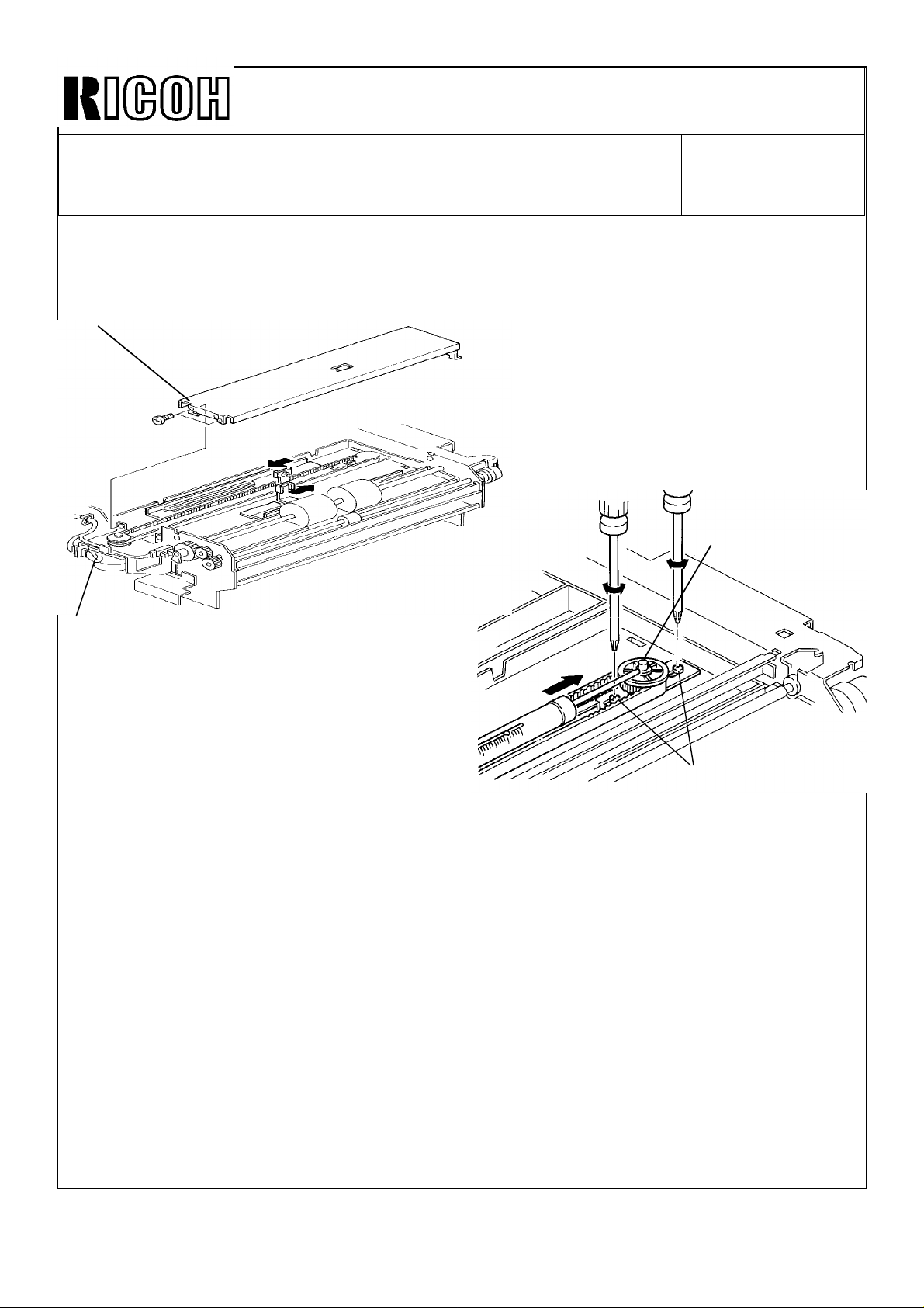
1. Remove the duplex unit and the duplex cover (4 screws).
2. Turn over the duplex unit as shown.
3. Unhook the sensor harness [A] clamped on the bottom plate [B].
4. Remove the bottom plate [B] (2 screws and 2 hooks).
5. Move the jogger fences to the most inward positions manually.
6. Loosen two screws [C] for the pulley bracket.
7. Press the pulley shaft [D] using a tension gauge as shown.
8. Tighten the screws [C] when the tension gauge shows between 110 and 140g.
NOTE: If the drive belt tension is higher than the above values, the jogger drive
motor control might step-out due to the excess load.
Page 4

Im!xml
Technical Bulletin
No.
RTB-002
SUBJECT: Inverter Unit Jams (“l” area misfeed)
PREPARED
CHECKED BY:
CLASSIFICATION:
❑ Action Required
■ Troubleshooting
❑ Retrofit Information
SYMPTOM:
“l” area misfeeds occur. Misfed paper is observed in the inverter unit.
This problem occurs especially with thick
CAUSE:
Since the larger feed force is required to feed the thick paper inversion, if the pressure of
the return pinch roller in the inverter unit is Io
BY:
#---
FROM: Copier Technical Support Section
❑ Revision of service manual
❑ Information only
❑ Other
paper
and small
W,
rnisfeeds may
size paper (A5, 51/2 x 81/2).
MODEL: F200 Type X/Y
occur in the inverter section.
DATE:
PAGE: 1 of 2
July 15, ’92
ACTIONS:
Check the return pinch roller pressure according to the following procedure.
1.
2.
3.
Page 5

Technical Bulletin No. RTB-002
SUBJECT: Inverter Unit Jams ("I" area misfeed) DATE: July 15, ’92
PAGE: 2 of 2
5. If the pressure is low, remove the pinch
roller bracket [F] (2 screws) and remove
the cushions [G] for the pinch roller
bracket.
CAUTION:
The pinch roller pressure can be adjusted
by changing the pinch solenoid position,
however, we cannot recommend doing
this for this problem for the following reason.
[J]
[H]
[G]
[F]
[I]
Since the stopper [H] for the inverter unit
lock lever [I] and the solenoid bracket [J]
are one part, if you move the solenoid
bracket position, the lock lever home position would also be changed. This would
make it possible to set the lock lever [I] in
the wrong position (left of the pin [K])
when the inverter unit is closed.
[K]
OK NG
[K]
[K]
Page 6
Rll(mMl
Technical Bulletin
No.
RTB-003
SUBJECT: Duplex Jams (F Area)
PREPARED BY: H.
CLASSIFICATION:
❑
Action Required
■
Troubleshooting
❑
Retrofit Information
SYMPTOM:
Jams occur in the duplex unit (“F” area Jams).
CAUSE:
Due to static electricity of fed paper, the sheets stick to each other and cause jams in the
duplex tray.
COUNTERMEASURES:
Terash”
❑
Revision of service manual
❑
Information only
❑
Other
FROM: Copier Technical Support Section
MODEL: F200 Type X/Y
DATE:
PAGE: 1 of 2
July
22, ’92
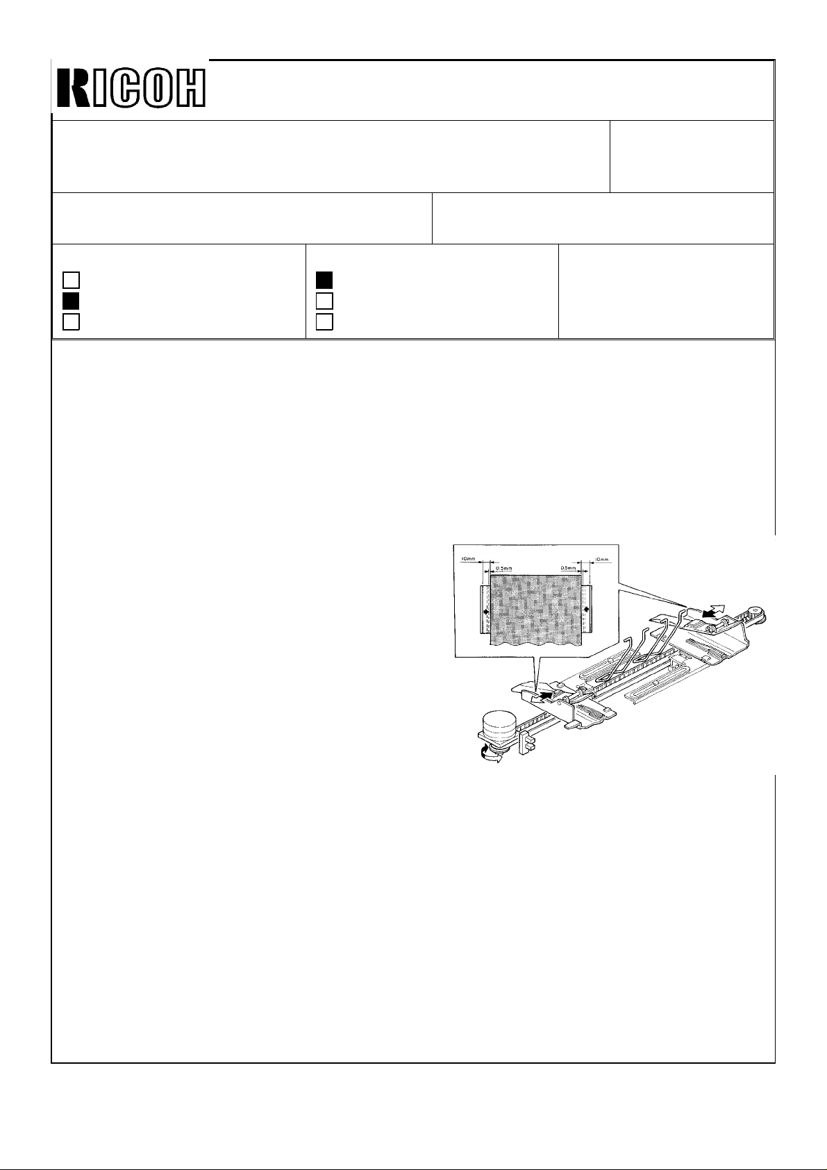
The material of the anti-static brushes in the duplex unit has been changed from stainless
steel to amorphous fiber which has high anti-static characteristic. They are applied from
the following productions:
F200 Type Y (A084) : June 1992 productions onward.
F200 Type X
Modification details will be announced by a later MB.
In the field:
If you have this type of jam, please follow the procedure below:
1. Slide out the duplex unit.
2. Open the duplex fork gate unit as
shown.
3. Remove the old anti-static brush
[A] with the grounding plate [B] (2
screws).
4. Install the new anti-static brush [C]
(P/N AA1 20061 ) with the grounding plate [B] (2 screws),
(A083) : May 1992 productions onward.
[A]
NOTE:
. Make sure the brush holder is
neath the gate
. Make sure the grounding plate po
as shown.
pawls
as shown.
Page 7
I{ouml
Technical Bulletin No.
RTB-003
SUBJECT: Duplex Jams (F Area)
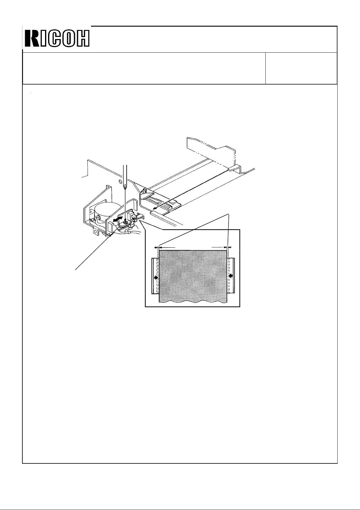
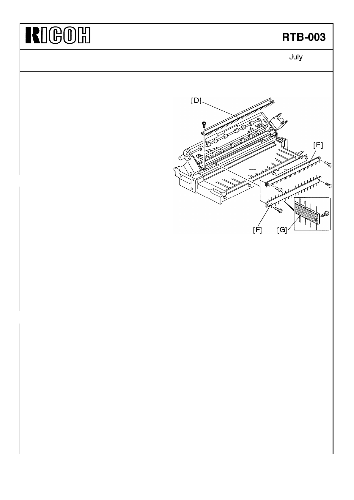
5. Remove the old brushes
[E] (2 screws each).
6. Install the new brush [F]
AA120062) so that the aluminum
seal [G] faces the bracket.
[D] and
(P/N
DATE:
PAGE: 2 of 2
July
31, ’92
Page 8

I{m(mil
Technical Bulletin
No.
RTB-004
SUBJECT: Drum damage by adhered toner on the development
sleeve
PREPARED BY:
CHECKED
CLASSIFICATION:
❑ Action Required
■ Troubleshooting
❑ Retrofit Information
SYMPTOM:
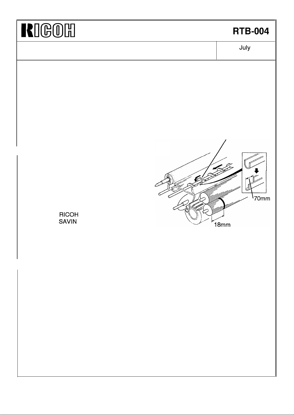
Toner adheres on the surface of the lower development sleeve (about 18mm from the
front end) and it makes scratches on the drum. This shows black lines on the copy image.
CAUSE:
The cross mixing system mixes the
developer in the development unit. The
mixing vane [A] transports developer to the
rear and the auger [B] transports it to the
front.
The development motor turns at slower
speed after image development to remove
the developer on the development sleeves.
This operation reduces developer to the
mixing vane, however, the auger continues
turning and transports developer to the
front side of the development unit. This in-
creases developer amount at the paddle
roller front side area [C].
This uneven developer condition will normally be eliminated by the next copy cycle.
However, if copies are frequently made
one to each original, frequent slow down
operation continues to increase the
developer at the front side. The accumulated developer at the front side is brought
to the lower development sleeve and pack-
ed between the sleeve and the drum. This
large amount of developer makes friction
heat. Then, it melts and adheres toner on
the sleeve. Finally, accumulated adhered
toner on the sleeve damages the drum.
H. Terashita
BY=,~+==
FROM: Copier Technical Support Section
❑ Revision of service manual
❑ Information only
❑ Other
[B]
1
MODEL: F200 Type X/Y
[A]
I
DATE:
PAGE:
July 31, ’92
1
of 2
Page 9
Kmxml
Technical Bulletin
No.
RTB-004
SUBJECT: Drum damage by adhered toner on the development
sleeve
The toner adhesion occurs at about 30mm from the front end of the unit (18mm from the
sleeve end) for the following reasons:
1. The end of the auger guide [D] is located at about 30mm from the unit front end.
2. There is a peak of the magnetic force field of the lower sleeve located at that point.
COUNTERMEASURE:
To disperse the fallen developer from the
auger guide, the guide has been cut as
shown.
This modification has been applied from
July ’92 productions.
The auger guide cannot be replaced in the
field. This is because the guide is fixed on
the doctor blade. The following develop-
ment units are available as service parts,
DATE: July 31, ’92
PAGE: 1 of 2
[D]
A0843010RICOH(-17)
A0843016
A0843012
A0843014 HCS (-26) NRG (-22/25)
NOTE:
When you replace the damaged drum, the cleaning blade, which may be damaged by the
drum, should also be replaced at the same time,
RICOH
SAVIN
(-27)
(-15) NRG (-1 0/16)
Page 10

NKmMl
Technical Bulletin
No.
RTB-005
SUBJECT: EPROM Software History
PREPARED BY: H. Terashita
CHECKED
CLASSIFICATION
BY:~~.&?
:
❑ Action Required
❑ Troubleshooting
❑ Retrofit Information
This bulletin informs the
A084 5111/5112
A084 5131/5132
Suffix
Cut-in production
A
B
c
D
E
Mar. ’92
April ’92
May ’92
June ’92
July ’92
EPROM
(2Mbit
(2Mbit
/
❑ Revision of service manual
■ Information only
❑ Other
history of the main PCB for the model F200 type Y.
: Inch Version)
: Metric Version)
Changed items/Changed reasons
- The 2nd job in the preset mode could not use the stapling
function whenever the first job used stapling.
- The “Add Paper” indication did not disappear even if the
operator selected a different tray. This occurred only in
Cover/Slip sheet mode.
- If a CF had an odd number of pages, in 1 sided original
to 2 sided copy mode, the last copy was not fed out
automatically.
- The auto-staple function was not working in CFF mode.
- The cover sheet mode was not working in CFF mode.
- You could not exit from the SP mode if you stopped the
free run mode by touching the RESET key on the CRT.
- Eliminates SC 514,515,516,790,791, and 792 from the SP
data print out.
- Resets the Auto Drum Current Adjustment Mode and SC
Off Mode automatically whenever exiting from the SP mode.
- The copy quantity limit for sort mode was larger by 1 copy
than it should have been.
- The
function is added.
- Modifications on the RDS functions.
- This suffix EPROM handles data differently in SP mode
(see NOTE on the next page).
- Auto magnification change did not function when the CF
original size is selected in Cover/Slip Sheet mode.
- This EPROM corrects the data handling problem that
arose with the suffix D EPROM.
Savin/HCS
DATE:
PAGE: 1 of 2
FROM: Copier Technical Support Section
MODEL: F200 Type Y
—
serial number code (initial digits) print
July 31, ’92
Page 11

Kmm)ll+l
Technical Bulletin
No. RTB-005
SUBJECT: EPROM Software History
NOTE:
Only suffix D EPROMs have the following SP data handling:
1. Sensor output data (SP #7)
2. Setting of the ADF
SP mode. You have to exit the
A084 5121/5122 (512Kbit)
Suffix
Cut-in production
c
D
E
May ’92
June ’92
July
’92
and CFF
does not change during copy cycle.
registration adjustments can be changed only once in the
SP
mode before the next setting change on the CRT.
Changed items/Change reasons
- Optimizes actual toner supply amount.
- Enables the Clear/Stop key function in
mode.
- Changes the sorter by-pass tray drive timing in the paper
exit mode from the duplex tray.
- Corrects malfunctions in the SC off mode.
—
DATE:
PAGE: 2 of 2
ADF/CFF
July 31, ’92
free run
CAUTION:
When you make any
reading speed of the
Reading speed of the EPROMs must be faster than
2Mbit EPROM :
1
Mbit EPROM :
512Kbit
Most of the EPROM have their reading speed indicated
Example)
EPROM :
copy of the EPROMs of this model, please take care about the
EPROMs as follows:
<150
ns
<150
ns
<120
ns
µ PD27C2001D-15 (Reading Speed =
the values below:
on them.
150 ns)
Page 12
Technical Bulletin No. RTB-006
SUBJECT: Low Temperature Idling Mode (230V version only) DATE: Sept. 15, ’92
PAGE: 1 of 3
PREPARED BY: H.Terashita
CHECKED BY:
CLASSIFICATION:
Action Required
Troubleshooting
Retrofit Information
A capability limitation of the F200 is that, due to the limitation of the power to the copier, it
has a low temperature idling mode.
To minimize the occurrence of the idling time, the following modifications have been
applied.
1. Fusing Lamps
To increase the fusing heat output during the copy cycle, the fusing lamp of 950W, which
is used during the copy cycle, has been changed to 1000W.
The other lamp (720W) was also changed to 670W to keep the total power consumption
the same as before. This is because all the ac components, such as the transformer and
circuit breaker, are designed for a total power of 1670W (1000+670W).
Revision of service manual
Information only
Other
FROM: Copier Technical Support Section
MODEL: F200 X/Y
(230V version only)
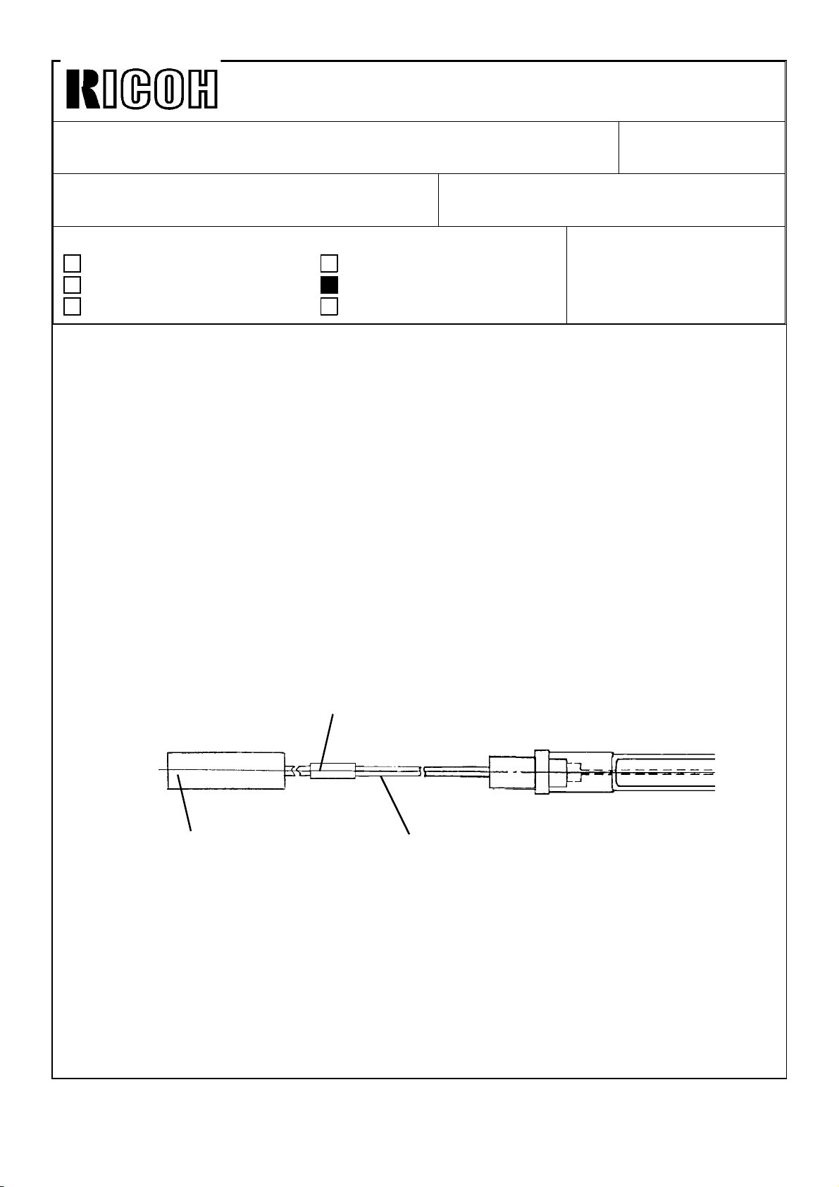
To distinguish the old and new lamps, a white tube has been added to the front lead wire
(black) of the fusing lamp (see figure).
White Tube
Connector
White : 670W
Red : 1000W
The new lamps have been implemented to the production machines as follows:
F200 Type X (A083) : August ’92 productions onward
F200 Type Y (A084) : September ’92 productions onward
Front Lead Wire
(Black)
Page 13
Technical Bulletin No. RTB-006
SUBJECT: Low Temperature Idling Mode (230V version only) DATE: Sept. 15, ’92
PAGE: 2 of 3
2. Software
To continue the copy run in low fusing temperature conditions as long as possible, the
software has been changed to lower the copy speed when the fusing temperature drops to
a certain temperature.
The copy speed is decreased by approximately 25% when the fusing temperature drops
below the lower limit temperature which is determined by the SP and User Tool settings
(see manual page 2- 96). For example, for the default settings, the slow-down copy cycle
will start when the temperature drops below 169°C.
Once the machine shifts to the slow-down copy mode, the mode is kept until the copy job
is finished even if the fusing temperature is recovered during the copy job.
Even if the slow-down mode is applied, the fusing temperature may drop in certain
conditions, such as A3 continuous copy run. A lower limit safety temperature has been
newly added to stop the copy run and to avoid any poor fusing problems when the
temperature drops below it. The lower limit safety temperature is lower than the lower limit
temperature by 5°C (164°C at default settings).
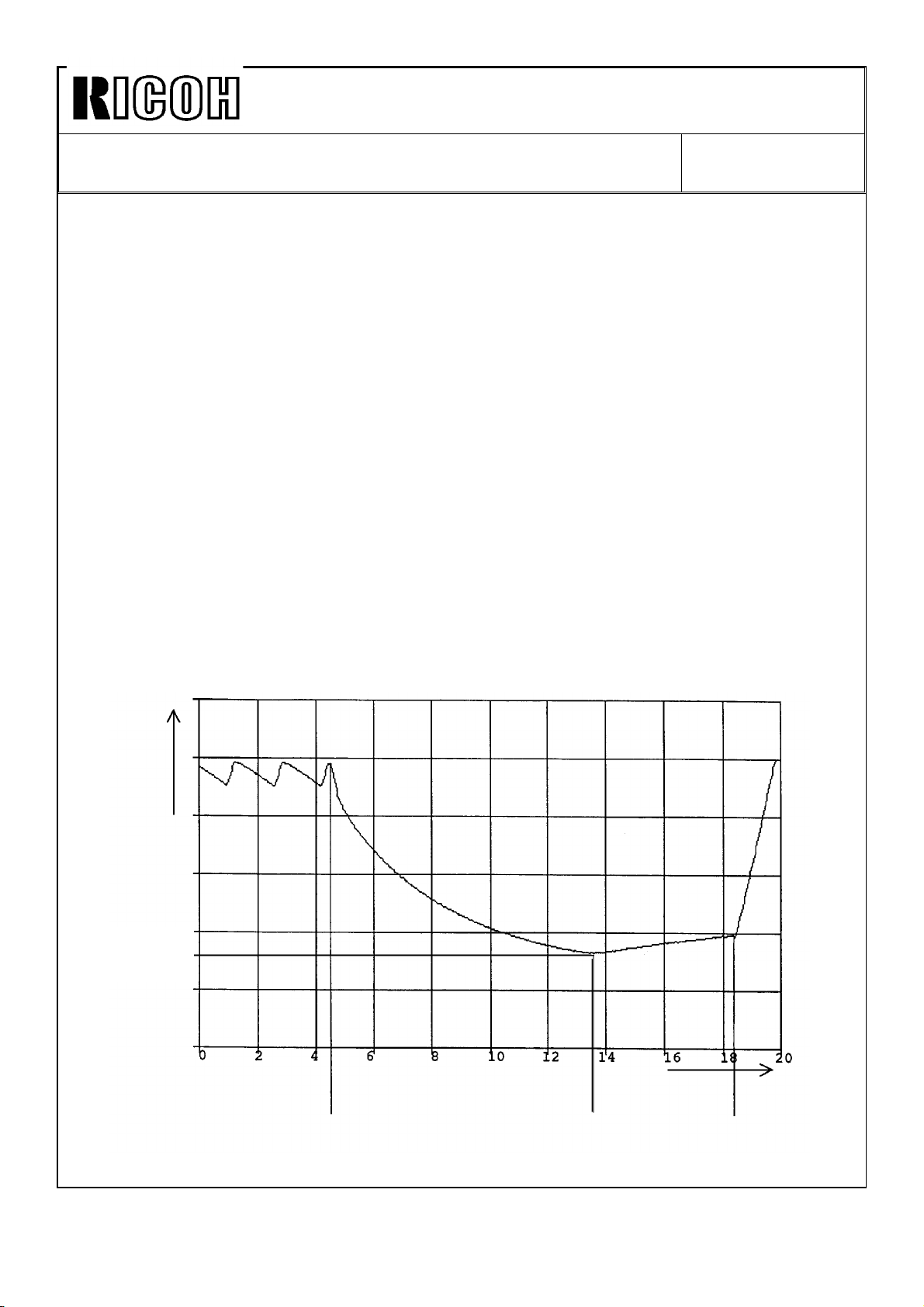
The following chart shows an ideal fusing temperature change in continuous copy run with
this new software.
Fusing Temp. °C
Lower Limit
Temperature
Start
Slow down
Min.
Stop
Page 14

Technical Bulletin No. RTB-006
SUBJECT: Low Temperature Idling Mode (230V version only) DATE: Sept. 15, ’92
PAGE: 3 of 3
The slow-down mode software has been applied to the following EPROMs on the main
PCB:
Type X : From August ’92 productions onward
A083 5131C
A083 5132C
A083 5121C
A083 5122C
Type Y : From August ’92 productions onward
A084 5131F
A084 5132F
A084 5121F
A084 5122F
There is no relationship between the new fusing lamps and the new software. You can use
the new EPROMs on the old machine without changing the fusing lamps and vice versa.
CAUTION:
The fusing lamps must be replaced as a set. If only the high output lamp is replaced to
1000W and old 720W lamp remains unchanged, the total current exceeds the rated values
of the ac components and may, in the worst case, cause damage and fire.
Page 15

Technical Bulletin No. RTB-007
SUBJECT: EPROM Software History DATE: Sept. 15, ’92
PAGE: 1 of 3
PREPARED BY: H.Terashita
CHECKED BY:
CLASSIFICATION:
Action Required
Troubleshooting
Retrofit Information
This bulletin describes the EPROM history of the main PCB for the model F200 type X.
1. Operation Unit EPROMs
A083 5251/5252 (1Mbit : Inch Version)
A083 5256/5257 (1Mbit : Metric Version)
Suffix Cut-in production Changed items/Changed reasons
A July ’92 - Spelling mistake corrections
Revision of service manual
Information only
Other
- The "side to side registration adjustment", which is
only for the type Y, has been removed from the SP
mode 9 page 3.
- Inhibit to enter "2" for the paper designate page data
in; Single sided original duplex, Cover sheet, and Paper
designate modes when "Copy onto cover sheet" is set
in the User Tool.
- Enable canceling the Staple mode automatically in
staple inhibit modes, such as single feed and platen
copy modes.
FROM: Copier Technical Support Section
MODEL: F200 Type X
CAUTION:
There are some EPROMs which are not compatible to those used on the F200 even if the
memory size is the same (1Mbit). The following EPROMs are used on the F200.
Mitsubishi M5M27C101K-15
AMD Am27C010-155DC
Intel D27C010-150V10
Page 16

Technical Bulletin No. RTB-007
SUBJECT: EPROM Software History DATE: Sept. 15, ’92
PAGE: 2 of 3
2. Main PCB
A083 5111/5112 (2Mbit : Inch Version)
A083 5131/5132 (2Mbit : Metric Version)
* Suffix A has been applied from the 1st mass-production.
Suffix Cut-in production Changed items/Changed reasons
B July ’92 - The RDH motor remained on when the front door
was opened and closed during the original number
counting mode.
- Start key stayed red when CFF, both cover sheet
and copy onto cover sheet modes were selected.
- A single feed original in interrupt mode was not fed
out when the interrupt mode was canceled.
- P2 jam occurred when;
Original=11x17, Paper=81/2x11, Full size, Stack, and
copy quantity=2
C Aug. ’92 - Optimize the side erase amount.
- RDH fan motor remained on if the SC and Jam, or
SC and door open happened at the same time.
- An incorrect message was displayed when the start
key was pressed in platen or single feed mode with
stapling.
- When originals were set in the RDH and the start key
was pressed after stopping single feed copying, an
RDH jam occurred after the single feed original was
fed out.
- When the single feed mode copy was made with
originals in the RDH, if the start key was pressed just
when the start key turned green, the copying would not
stop until the Stop key was pressed.
- Enable transfering an old user code counter data to a
new one when the user code change function in the
User Tool is used.
- Software change related to the low temperature idling
mode (metric version only).
Page 17
Technical Bulletin No. RTB-007
SUBJECT: EPROM Software History DATE: Sept. 15, ’92
PAGE: 3 of 3
A083 5121/5122 (512Kbit)
Suffix Cut-in production Changed items/Changed reasons
B July ’92 - To adjust the ROM addresses to meet the 2Mbit
ROMs suffix B.
C Aug. ’92 - The junction gate solenoid in the inverter unit stays
on after face down and duplex copying. If the solenoid
check in SP mode is performed at this time, the wrong
error code would be displayed.
To prevent this, the software has been changed to
de-energize the solenoid when the main motor is
stopped.
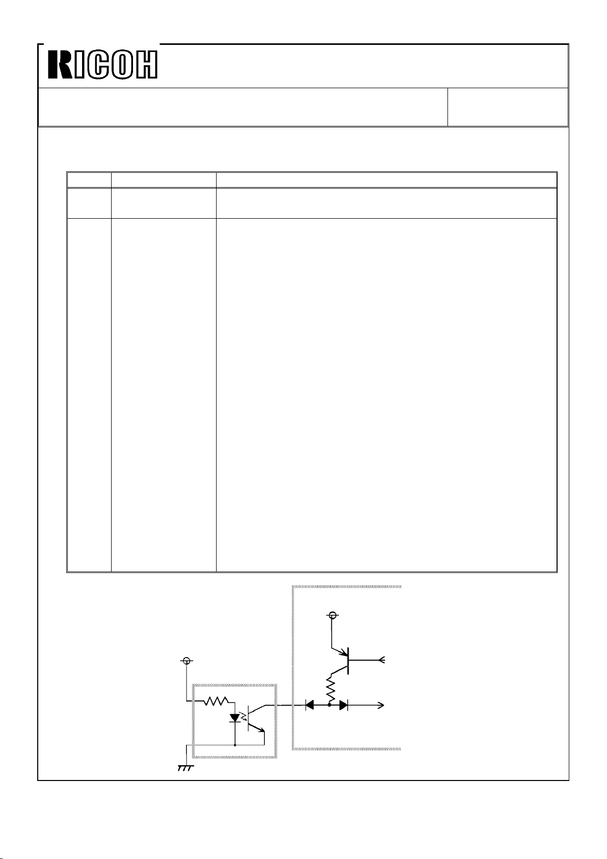
- The sensor check in the SP mode is performed by
checking the sensor output while the sensor power is
turned on and off. The sensors which are connected to
the interface PCB, the tray upper and lower limit, paper
end, paper exit, and toner cartridge sensors, were
scanned by scan pulse signals from the main PCB.
Since the scan pulse signals are used for both power
and output signal for these sensors, the sensor check
does not work correctly (see figure).
So, the sensor check for these sensors has been
changed to enable only for ON check.
- The paper end sensor check has been changed to
enable only when the paper exists in the tray.
- The condition of the paper tray upper and lower limit
sensor check has been changed so that both are on or
off at the same time. Both sensor numbers will be
indicated under these conditions.
+12V
Sensor
+12V
Scan
Output
Interface PCB
Page 18

Technical Bulletin No. RTB-008
SUBJECT: EPROM Software History DATE: Sept. 15, ’92
PAGE: 1 of 3
PREPARED BY: H.Terashita
CHECKED BY:
CLASSIFICATION:
Action Required
Troubleshooting
Retrofit Information
This bulletin describes the EPROM history of the main PCB for the model F200 type Y.
1. Operation Unit EPROMs
A084 5251/5252 (1Mbit : Inch Version)
A084 5256/5257 (1Mbit : Metric Version)
* Suffix A has been used from the 1st mass-productions.
Suffix Cut-in production Changed items/Changed reasons
B May ’92 - Spelling mistake corrections.
C June ’92 - Spelling mistake corrections. (Inch version only)
Revision of service manual
Information only
Other
- Reproduction priority settings have been changed.
77% -> 74%, 85% -> 77% (Inch version only)
FROM: Copier Technical Support Section
MODEL: F200 Type Y
CAUTION:
There are some EPROMs which are not compatible to those used on the F200 even if the
memory size is the same (1Mbit). The following EPROMs are used on the F200.
Mitsubishi M5M27C101K-15
AMD Am27C010-155DC
Intel D27C010-150V10
Page 19

Technical Bulletin No. RTB-008
SUBJECT: EPROM Software History DATE: Sept. 15, ’92
PAGE: 2 of 3
2. Main PCB
A084 5111/5112 (2Mbit : Inch Version)
A084 5131/5132 (2Mbit : Metric Version)
Suffix Cut-in production Changed items/Changed reasons
F Aug. ’92 - Optimize the side erase amount.
- Enable APS and AR/E functions with 11"x147/8"
originals.
- Enable transfering the old user code counter data to
a new one when the user code change function is
used.
- Correct mis-indication of the paper end when the slip
sheet runs out in the slip/paper designate modes.
- Software changes related to the low temperature
idling mode (metric version only).
A084 5121/5122 (512Kbit)
Suffix Cut-in production Changed items/Changed reasons
F Aug. ’92 - The junction gate solenoid in the inverter unit stayed
on after face down and duplex copying. If the solenoid
check in SP mode was performed at this time, the
wrong error code would be displayed.
To prevent this, the software has been changed to
de-energize the solenoid when the main motor is
stopped.
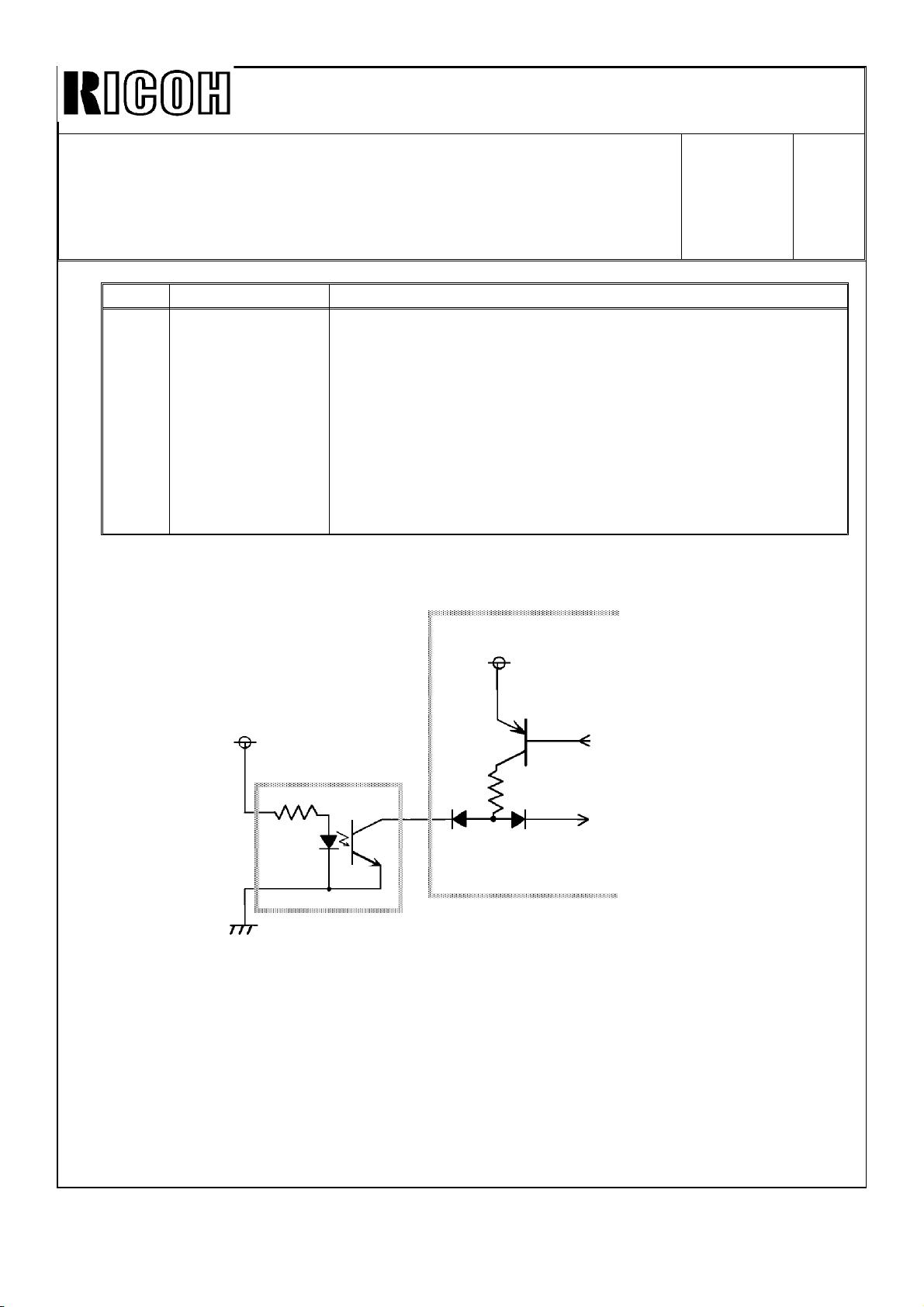
- The sensor check in the SP mode was performed by
checking the sensor output while the sensor power
was turned on and off. The sensors connected to the
interface PCB, the tray upper and lower limit, paper
end, paper exit, and toner cartridge sensors, were
scanned by scan pulse signals from the main PCB.
Since the scan pulse signals were used for both power
and output signal for these sensors, the sensor check
did not work correctly (see the figure on the next
page). So, the sensor check for these sensors has
been changed to enable only for ON check.
- The paper end sensor check has been changed to
enable only when the paper exists in the tray.
(continued)
Page 20
Technical Bulletin No. RTB-008
SUBJECT: EPROM Software History DATE:
Sept. 15,
’92
PAGE: 3
of 3
Suffix Cut-in production Changed items/Changed reasons
F Aug. ’92 - The condition of the paper tray upper and lower limit
sensor check has been changed so that both are on or
off at the same time. Both sensor numbers will be
indicated under these conditions.
- If an SC condition had occurred while the 2nd tray
was lowering, the tray would not move up again after
the SC reset.
- Enable the 7% fixed toner supply function when the
Vsg adjustment in the process control data initialization
fails.
+
+12V
Sensor
+12V
Scan
Output
Interface PCB
Page 21

Icn(mll
Technical Bulletin
No.
RTB-009
SUBJECT: Fusing Temperature Adjustment
PREPARED BY: H.
CLASSIFICATION:
❑ Action Required
❑ Troubleshooting
Terashita
—
■ Revision of service manual
❑ Information only
DATE:
PAGE: 1 of 2
FROM: Copier Technical Support Section
MODEL: F200 X/Y
NOV.
30, ’92
❑ Retrofit Information ❑ Other
The fusing temperature display in SP mode of the F200 is different from that of the
previous models, such as those of the F20 series. This bulletin explains the temperature
display system of the F200 and revises the fusing temperature adjustment procedure.
1. Fusing Temperature Display and the Fusing Temperature Adjustment in SP mode
The displayed figure is calculated using the thermistor resistance and will not be affected
by the setting of the fusing temperature adjustment in SP mode.
The main PCB has a table to convert the thermistor resistance into a temperature figure.
The main PCB, then controls the fusing lamps according to the calculated figure, so that
the lamps are turned on at 195°C and off at 198°C.
The actual hot roller temperature is not the same as the temperature measured with the
machine’s thermistor because of the tolerance of the thermistor. Therefore, the fusing lamp
on/off temperature is compensated machine by the machine. This compensation is done
by changing the setting of the SP mode “Fusing Temperature Adjustment”,
The displayed figure is not the actual temperature, at the time the compensation is applied.
2. Fusing Temperature Adjustment
Please refer to the service manual page 5-94,
Add the following:
Adjustment Target :195 ± 1 °C
NOTE: The fusing temperature adjustment is only necessary when you have
replaced the fusing thermistor.
Page 22

Iul(mlxl
Technical Bulletin
No.
RTB-009
SUBJECT: Fusing Temperature Adjustment
Correct the steps from step 9
9. Using a digital thermometer and probe, measure the temperature at the middle of
the hot roller when the lamp is turned
10. If the measured temperature is out of the adjustment range, change the setting of
the fusing temperature in SP mode (9).
NOTE: Use + to lower the
11. Repeat steps 9 to 10 and
12. Reassemble the parts.
NOTE: When assembling the
connectors are set to
as follows:
on.
temperature.
confirm the lamp on temperature,
safety switch harness connectors, make sure the
the correct position.
DATE: Nov. 30, ’92
PAGE: 2 of 2
Page 23
I{m(ml
Technical Bulletin No. RTB-010
SUBJECT: Duplex Jogger Drive Belt Tension Adjustment
PREPARED BY: H,
CHECKED
CLASSIFICATION:
BY:/~
.-
Terashita
FROM: Copier Technical Support Section
DATE:
PAGE: 1 of 1
MODEL: F200 X/Y
Nov.
30, ’92
❑ Action Required ■ Revision of service manual
❑ Troubleshooting
❑ Retrofit Information
.
The duplex jogger drive belt tension adjustment has been revised by the RTB-001 issued
on July 15, 1992,
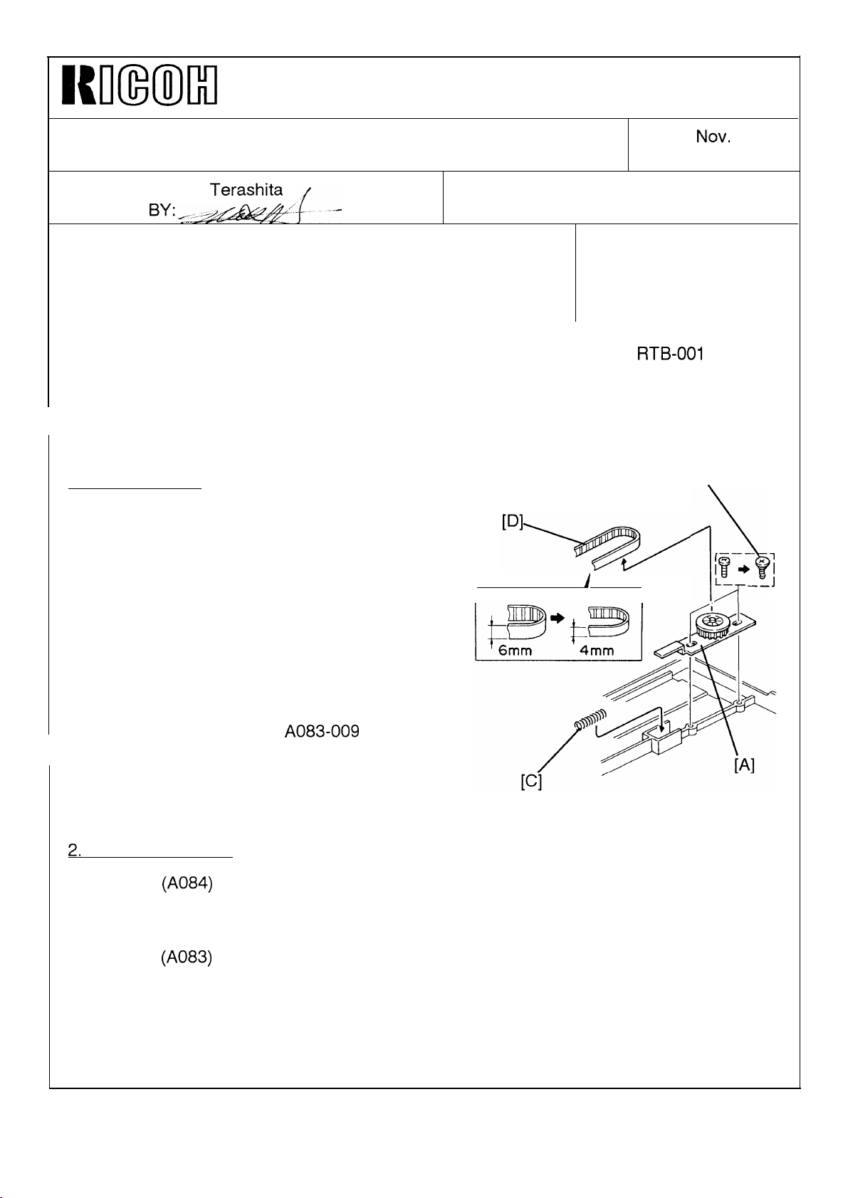
The jogger fence drive belt tension mechanism has been reviewed to facilitate assembling
in the factory, and changed to an adjustment free mechanism as shown below,
1. Modified Items
The mounting holes of the timing pulley bracket
[A] has been enlarged and fixed by shoulder
screws [B].
A tension spring [C] has been added.
The width of the timing belt [D] has been
changed from 6mm to 4 mm to decrease the
drive load of the jogger fences.
❑ Information only
❑ Other
[B]
.—.
r-
A
I
,
j\
1P+ ‘;
L–
/T
__J
As the result, no adjustment is required when
servicing,
Please refer to the MBs,
021, for details,
2,
Modification Cut-in
Type Y
-1 5/1 7/22/25/27
Type X
-1 7/22/25/27
-16
(A084)
(A083)
A083-009
From September ’92 production onward
From September ’92 production onward
From October ’92 production onward
and A084-
Page 24
Imm)lxl
Technical Bulletin
No. RTB-011
SUBJECT: Improper Duplex Jogger Fence Movement
PREPARED BY: H, Terashita
CHECKED BY
CLASSIFICATION:
❑ Action Required
■ Troubleshooting
❑ Revision of service manual
❑ Information only
FROM: Copier Technical Support Section
MODEL: F200 X/Y
❑ Retrofit Information ❑ Other
We have found that there is a possibility of the following problem on the
informs you of countermeasures, and gives a tip
for field troubleshooting.
mm
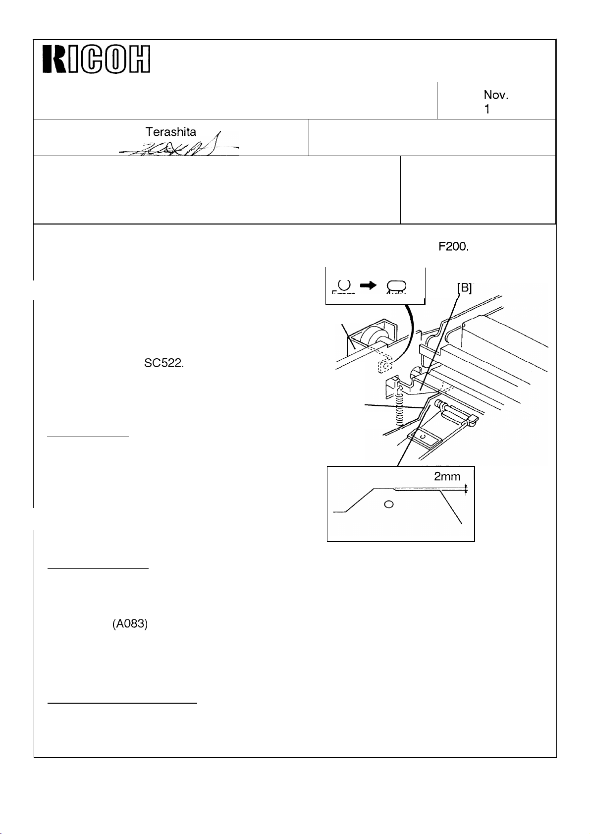
PROBLEM:
The rear jogger fence [A] touches the duplex
positioning roller arm [B]. This affects the jogger
fence movement and may cause duplex paper
feed skew and
SC522.
[c]
x
DATE:
PAGE:
F200.
This bulletin
NOV.
1
of 1
30, ’92
COUNTERMEASURES:
Modified items:
The upper mounting hole of the positioning
roller bracket [C] has been changed from 5mm
to 4x6mm to assure the vertical position of the
bracket.
The rear jogger fence has been cut by 2mm as
shown to widen the gap between the fence and
the arm,
Modification cut-in:
Type Y (A084)
-1 5/1 7/22/25/27
Type X
-1 7/22/25/27
-16
(A083)
From September ’92 production onward
From September ’92 production onward
From October ’92 production onward
[A]
2mm
Troubleshooting in the field:
If the fence is touching the positioning roller arm, remount the positioning roller bracket at the highest position.
Page 25
I{m(ml
Technical Bulletin
No. RTB-012
SUBJECT: Hot Roller and Pressure Roller Replacement DATE:
PAGE: 1 of
PREPARED BY: H. Terashita
.
. .
CLASSIFICATION:
❑ Action Required
■ Revision of service manual
FROM: Copier Technical Support Section
MODEL: F200 X/Y
❑ Troubleshooting
❑ Retrofit Information
Please add the following note in your service manual, page 5-90.
NOTE: Whenever the hot roller and pressure roller are replaced, check the nip
width and adjust fusing pressure
adjustment, manual page 5-95)
The reason for the nip
follows:
width check at
❑ Other
the
if necessary. (See fusing pressure
hot roller
and
pressure roller replacement is as
Nov.
30, ’92
1
The nip band is an important factor for image fusing and must be maintained.
by
The nip band width is determined
conditions. When the rollers are replaced, nip band width may be changed. Especially, the
pressure roller affects the nip band width because of variations of the silicon rubber
hardness.
Therefore, whenever you replace the hot roller and pressure roller, first check the nip band
(8,
width by using SP mode
out of the adjustment range (10 +/- 0.5 mm).
fusing pressure check mode) and then adjust it if the width is
not only the roller pressure but also the roller surface
Page 26

Technica l Bulletin No . RTB-01 3
SUBJ ECT: Low Im ag e De nsity I n M ultip le Co py Ru n DATE: Feb . 15, ’ 9 3
PAGE: 1 o f 1
PREPARED BY: H .Tera shit a
CHECKED BY:
CLASSIFICATION:
Action Required
Troubleshooting
Retrofit Information
SYMPTOM :
In multiple copy runs, image density goes down gradually even if small image area
or igin als ar e us ed.
CAUSE:
We have found that the toner supply amount when the Toner Density Selection setting in
the SP mod e (SP#10 p age 3) is at 30% is not enou gh for multip le co p ying of A4/ 81/2"x11"
size.
The toner is supplied by the toner supply roller, which has an A3/11" x 17" width. The
toner amount is correct for 30% area image, however, only toner at the A4/81/2"x11" area
(middle part) is consumed, and this causes low toner concentration at that part.
Revision of service manual
Information only
Other
FROM: Copier Technical Support Section
MODEL: F200 X/Y
COUNTERMEASURES:
Since the actual cause of the low ID problem in multiple copying was not clear, the factory
settin g o f th e ton er d ensity selec tio n was s elected as HIGH o nly o n t he Decem ber 1992
productions as a temporary solution.
From th e Jan uary 1993 p ro d uc tio n, th e fact or y s ettin g of the t on er den sity selec tio n in the
SP mod e has been returned to NORMAL and the toner supply amount has been changed
fro m 30% to 45%.
Please note that we will not modify the software to correct the toner supply amount d ata
for the 30% supply mode. This is because that you must check if the software is new or
old whenever you determine the proper toner supp ly amount setting for each machine.
In case of the low ID problems, the toner density selection in the SP mode is easily set to
HIGH or VHIGH b y field technicians. As for other models, toner scattering problems may
oc cu r if th e high er to ner den sity s electio ns are selec ted , even if to ner co nc entr atio n is
reasonably high in the development unit. There is a possibility of having toner adhering
pr ob lem o n th e d evelop m ent r o ller in an extr emely h igh to n er c on c entr atio n c o nd itio n even
if the machine has the new development unit with the modified auger guide (Refer to the
RTB-004).
To minimize the side effect pro blems, we recommend to return the toner density selection
to NORMAL and use the toner supply amount selection or ID selection in ADS mo de
instead (SP Special Features page 3), if customers need higher image density.
Page 27
Technica l Bulletin No . RTB-01 4
SUBJ ECT: EPROM Software History DATE: Feb . 15, ’ 9 3
PAGE: 1 o f 3
PREPARED BY: H .Tera shit a
CHECKED BY:
CLASSIFICATION:
Action Required
Troubleshooting
Retrofit Information
This b ulletin d esc rib es th e EPROM hist or y of t he mo de l F200 type Y.
1. M ain PCB
A084 5111/5112 (2Mbit : Inch Version)
A084 5131/5132 (2Mbit : Metric Version)
Suffix Cut-in produc tion Changed items or reasons
G October ’92 * During the single copy run in the platen mode, if the Start key
is pressed before the main motor operation for the previous
copying job sto ps, the ID sensor pattern control counters are
reset. This results in no ID sensor pattern produc tion if this
operation is repeated.
* During the machine off condition by the weekly timer, the
screen saver function did not work.
*The default (not the factory) setting of the toner density
selection has been changed from HIGH to NORMAL.
* When t he d ifferen t size o rig inals feedin g m o de is s elec ted by
User Tools, large size copy papers hits the jogger bar of the
sorter stapler and causes jams in the ADF, sort, and single
copy modes.
* The staple modes have been inhibited in the different size
or ig inals feed ing m od e is selec t ed .
* To enable the handling of SP/UT printing data by a PC, the
Line Feed (0AH) co mman d h as been ad d ed to th e Carriag e
Return sig nal fo r eac h line p r int d ata. The En d Of File (1AH )
has also been added to the end of the print data.
You have to change the settings of the printer so as not to
perform the line feed by the new command. Otherwise, two
lines will be used for one printed line.
* When th e user c od e is c hec ked by the Us er Too ls, "967295"
was displayed if no user code is registered.
Revision of service manual
Information only
Other
FROM: Copier Technical Support Section
MODEL: F200 Type Y
Page 28
Technica l Bulletin No . RTB-01 4
SUBJ ECT: EPROM Software History DATE: Feb . 15, ’ 93
PAGE: 2 o f 3
Suffix Cut-in produc tion Changed items or reasons
H December ’92 * The first three digits of the serial number printout of SP/UT
modes for Gestetner/Nashua versions are corrected as follows:
U.S. versio ns : 490 -> 491
Euro pe ver sion s : 491 -> 490
* Dur ing fu sin g low tem p era tur e id lin g, c o py ing is aut o mat ica lly
resumed even if the ADF is opened or closed.
* The following counters were also double counted in A3/11"x17"
doub le count mode. They were changed to single increment.
Total copy c ounters in copy and original jam counters
PM counter
Daily and Weekly counters
J February ’93 * In the Cover/Slip mode copying, if the Cover/Slip tray runs out
papers, the Tray key cannot be used at all. Even if papers are
sup p lied in t he t ray , t he Tr ay k ey r ema ined in op er ative.
* The counting method o f the following counters in the SP mo de
has been changed.
In Duplex Modes
- Total copies by paper sizes : Double -> Single count
Following counters are changed to count even if in the blank
copy output mode.
- PM cycle counter
- Daily/weekly copy counters
- Total counters in jam/SC counters
All the SP co py counters will be incremented for Cover/Slip
sheets without copy image. The following copy co unters are
no t inc remen ted , as b efor e.
- Total number of copies
- Test mode copy c ounter
- Block copy co unter
- User code counters
A084 5121/5122 (512Kbit : Co mm o n)
Suffix Cut-in produc tion Changed items or reasons
G October ’92 To match the data address with the software of the 2Mbit ROMs.
H December ’92 To match the data address with the software of the 2Mbit ROMs.
J February ’93 To match the data address with the software of the 2Mbit ROMs.
Page 29
Technica l Bulletin No . RTB-01 4
SUBJ ECT: EPROM Software History DATE: Feb . 15, ’ 93
PAGE: 3 o f 3
2. Operation Unit PCB
A084 5251/5152 (1Mbit : Inch Version)
A084 5256/5257 (1Mbit : Metric version)
Suffix Cut-in produc tion Changed items or reasons
Inc h Metr ic
D C January ’93 * The location of the door in the display for the sorter
misfed paper removal is corrected.
* ARDF misfeed message has been changed from "...
inside the covers." to "... on the covers".
* initial digits of the serial number in SP mode has been
co rr ect ed 490 < - > 491 ( Nasu a/ Gestetn er vers ion s) .
* Weekly timer message in User Tool # 7 has been
changed from "To register a time..." to "To register an
access cod e...".
* The CFF size has b een ch ang ed fro m 11"x91/2" t o
12"x141/2" (Metric Version Only).
NOTE:
The English ROM kit (only for Ricoh Metric versions) has different part numbers for each
EPROM . The EPROMs in t he ROM kit are eq uivalent as sh own belo w:
A385 5002 = A084 5256B
A385 5003 = A084 5257B
A385 5006 = A084 5266B
The part numbers in the ROM kit will be standardized with that of the production EPROMs
(A084 ....) from the next productions.
G October ’92 To match the data address with the software of the 2Mbit
ROMs.
H December ’92 To match the data address with the software of the 2Mbit
ROMs.
J February ’93 To match the data address with the software of the 2Mbit
ROMs.
Page 30
Technica l Bulletin No . RTB-01 5
SUBJ ECT: EPROM Software History DATE: Feb . 15, ’ 9 3
PAGE: 1 o f 3
PREPARED BY: H .Tera shit a
CHECKED BY:
CLASSIFICATION:
Action Required
Troubleshooting
Retrofit Information
This b ulletin d esc rib es th e EPROM s his tor y o f the mo d el F200 typ e X.
1. M ain PCB
A083 5111/5112 (2Mbit : Inch Version)
A083 5131/5132 (2Mbit : Metric Version)
Suffix Cut-in produc tion Changed items or reasons
D October ’92 * During the single copy run in the platen mode, if the Start key
is pressed before the main motor operation for previous
copying job sto ps, the ID sensor pattern control counters are
reset. This results in no ID sensor pattern produc tion if this
operation is repeated.
* During the machine off condition by the weekly timer, the
screen saver function did not work.
*The default (not the factory) setting of the toner density
selection has been changed from HIGH to NORMAL.
* If larg e size pap er ( A3/11"x17") remain ed in the d up lex tray
and was fed out without copying after a small paper size
(A4/81/2"x11") copying job is finished, the ID sensor pattern is
developed on the large size papers.
* To enable the handling of SP/UT printing data by a PC, the
Line Feed (0AH) co mman d h as been ad d ed to th e Carriag e
Return sig nal fo r eac h line p r int d ata. The En d Of File (1AH )
has also been added to the end of the print data.
You have to change the settings of the printer so as not to
perform the line feed by the new command. Otherwise, two
lines w ill b e us ed for o ne line p rin t.
* When th e user c od e is c hec ked by the Us er Too ls, "967295"
was displayed if no user code is registered.
Revision of service manual
Information only
Other
FROM: Copier Technical Support Section
MODEL: F200 Type X
Page 31

Technica l Bulletin No . RTB-01 5
SUBJ ECT: EPROM Software History DATE: Feb . 15, ’ 9 3
PAGE: 2 o f 3
Suffix Cut-in produc tion Changed items or reasons
E December ’92 * The first three digits of the serial number printout of SP/UT
modes for Gestetner/Nashua versions are corrected as follows:
U.S. versio ns : 492 -> 493
Euro pe ver sion s : 493 -> 492
* Dur ing t he fu sing lo w tem per atu re id lin g , c o p ying is
automatically resumed even if the RDH is opened or closed
* The following counters were also double counted in A3/11"x17"
doub le count mode. They were changed to single increment.
Total copy c ounters in copy and original jam counters
PM counter
Daily and Weekly counters
* In Simp lex-Dup lex, Dup lex-Dup lex, an d Imag e Overlay mo d es,
if the originals are set in the RDH, and more than 50 is entered
for the c o p y nu mb er, and th en t he o rig inals ar e rem oved an d
the Start key is pressed, more than 50 copies would be fed
into the duplex tray.
* When the original size is A4 sideways and the copy paper is
A4 lengthwise, if the APS is selected in staple mode copying,
"Check paper size" indication will be displayed and the
mac hin e stay s in "Please wait" c o nd itio n .
F February ’93 * The counting method o f the following counters in the SP mode
has been changed.
In Duplex Modes
- Total copies by paper sizes : Double -> Single count
Following counters are changed to count even if in the blank
copy output mode.
- PM cycle counter
- Daily/weekly copy counters
- Total counters in jam/SC counters
All the SP co py counters will be incremented for Cover/Slip
sheets without copy image. The following copy co unters are
no t inc remen ted , as b efor e:
- Total number of copies
- Test mode copy c ounter
- Block copy co unter
- User code counters
Page 32

Technica l Bulletin No . RTB-01 5
SUBJ ECT: EPROM Software History DATE: Feb . 15, ’ 9 3
PAGE: 3 o f 3
A083 5121/5122 (512Kbit : Co mm o n)
Suffix Cut-in produc tion Changed items
D October ’92 To match the data address with the software of the 2Mbit ROMs.
E December ’92 To match the data address with the software of the 2Mbit ROMs.
F February ’93 To match the data address with the software of the 2Mbit ROMs.
2. Operation Unit PCB
A083 5251/5152 (1Mbit : Inch Version)
A083 5256/5257 (1Mbit : Metric version)
Suffix Cut-in prod uction Changed items or reasons
B January ’93 * "RDH Side Registration Adj." in the SP mode has been
changed to "RDH Registration Adj.".
* Miss pellin g co r rec t ion .
* initial digits of the serial number in SP mode has been
co rr ect ed (492 < -> 493 : Nashua/Gestetner versions).
* Weekly timer message in User Tool # 7 has been changed
from "To register a time..." to "To register an access code...".
* The CFF size has been ch ang ed fro m 11"x91/2" to
12"x141/2" (Metric Version Only).
NOTE:
The English ROM kit (only for Ricoh Metric versions) has different part numbers for each
EPROM . The EPROMs in t he ROM kit are eq uivalent as sh own belo w:
A385 5102 = A083 5256
A385 5103 = A083 5257
A385 5106 = A083 5266
The part numbers in the ROM kit will be standardized with that of the production EPROMs
(A083 ....) from the next productions.
Page 33

Technica l Bulletin No . RTB-01 6
[G]
SUBJ ECT: Origina l Jam s in RDH ( P3 J ams) DATE: March 3, ’93
PAGE: 1 o f 3
PREPARED BY: H .Tera shit a
CHECKED BY:
CLASSIFICATION:
Action Required
Troubleshooting
Retrofit Information
SYMPTOM :
Orig inal jams at t he RDH inver ter sec tio n an d P3 in dic at or b link s on th e CRT.
Damage on the original leading edge, skew, dog ear, and accordion jams are observed in
most of the cases.
CAUSE:
The original leading edge hits the inner inverter guide plate [A] [ parts catalog page 176
ind ex 1] .
Revision of service manual
Information only
Other
[A]
FROM: Copier Technical Support Section
MODEL: F200 X/Y
[H]
[G]
COUNTERM EASURES:
In th e field:
You c an ob s erve if t he o r igin al hit s t he in ner inver ter gu id e p late b y o p enin g the invert er
unit guide and remove the antistatic brush b racket [ B] (2 screws) [P/C page 174 ind ex 11
and 12] .
1. Remove the front (6 screws) and rear (8 screws) covers of the RDH.
2. Remove t he m ot or d rive PCB b rac ket [C] (2 sc r ews) [ P/C p age 186 ind ex 11] .
3. Remove t he inver ter mo to r [D] ( 4 sc rew s) [P/C p ag e 180 ind ex 29 and 31].
4. Remove the timing belt tightner [E] (1 screw) [ P/C page 180 in dex 13 an d 27].
[I]
5. Remove th e inverter mo to r b rack et [F] ( 5 scr ews) [ P/C pag e 180 index 26].
Page 34

Technica l Bulletin No . RTB-01 6
SUBJ ECT: Orig inal J am s in RD H (P3 Ja ms) DATE: March 3, ’93
PAGE: 2 o f 3
6. Loosen four screws [G] (two each for the front and rear) fixing the inner inverter guide
plate.
7. Lift th e inner guid e p late and fix it at th e hig hest po sitio n.
In th e facto ry :
To prevent the paper from hitting the guide [H] , additional guides [I] have been added on
the inn er invert er g uid e plate, and the g ap b etw een the g uid e and ro ller has b een m ade
narrower (see figure) from January ’93 production.
B
C
Page 35

Technica l Bulletin No . RTB-01 6
SUBJ ECT: Orig inal J am s in RD H (P3 Ja ms) DATE: March 3, ’93
PAGE: 3 o f 3
[E]
[D]
[F]
Page 36

Technica l Bulletin No . RTB-01 7
SUBJ ECT: Erratic RDH Operation DATE: March 3, ’93
PAGE: 1 o f 3
PREPARED BY: H .Tera shit a
CHECKED BY:
CLASSIFICATION:
Action Required
Troubleshooting
Retrofit Information
SYMPTOM :
During or after cop y jobs, the RDH free runs or continuously feeds.
CAUSE:
CPU runs away and cannot contr ol the RDH operation. This is caused by an external
noise.
The vacu um g uid e plat e [ A] is elec tric ally float ed an d m ay ho ld th e electr o-s tatic pr od uc ed
by or igin al feed ing . When the c har ged st atic elect ric ity is dis ch arg ed , th e CPU may r un
away an d k eep th e feed mo to r o r blo wer fan m o to r o n c o ntin uo usly .
COUNTERM EASURES:
In the field s:
Revision of service manual
Information only
Other
FROM: Copier Technical Support Section
MODEL: F200 X
1. Remove t he u pp er left tab le [B] (4 sc rew s) [ P/ C p age 162 ind ex 10].
2. Remove th e co atin g [C ] o n th e vacu um g uid e plat e as sho wn .
3. Adh ere a p iec e o f co n du ct ive typ e t ape [D] so th at th e vacu um gu ide p lat e is g ro un ded
to the o rig in al tab le [ E].
In th e facto ry :
A grounding plate [ F] has been added (peened) on the vacuum guide plate [ A] [ P/C page
167 ind ex 7] s o t hat the g uid e p lat e is g ro un ded t o the m ach ine fr ame fr o m J anuar y ’ 93
production.
The new P/N o f th e vacuu m g uide p late is A3521520.
Page 37

Technica l Bulletin No . RTB-01 7
[F]
SUBJECT: Erratic RDH Operation DATE: March 3, ’93
PAGE: 2 o f 3
A
[B]
Page 38

Technica l Bulletin No . RTB-01 7
SUBJECT: Erratic RDH Operation DATE: March 3, ’93
PAGE: 3 o f 3
[D]
[C]
[E]
Page 39

Technica l Bulletin No . RTB-01 8
20gf
SUBJ ECT: Duplex Pick-up Roller M arks DATE: March 3, ’93
PAGE: 1 o f 1
PREPARED BY: H .Tera shit a
CHECKED BY:
CLASSIFICATION:
Action Required
Troubleshooting
Retrofit Information
The F200 is usin g the lo wer sid e feed sys tem in th e du p lex unit to keep t he hig h
productivity in duplex copy mode. As this is one of the machine limitation, two duplex
pick-up roller marks may be visible on the copy paper, especially thick papers are used,
due to this feed system.
We cannot eliminate these marks with this feed system, however, following modification
has been applied to the production line to give a possibility to minimize the roller marks.
Regarding the cut-in serial number, please refer to the MB issued in the future.
As shown in the figure, two spring hook holes have been added to the brackets [ A] (P/N
A0794806 → A0794807).
The original hole gives 70gf to the pick-up pressure plate. Two holes give 30gf and 20gf
as shown. The best position must be selected by trial and error by making duplex copies.
Revision of service manual
Information only
Other
FROM: Copier Technical Support Section
MODEL: F200 X/Y
These position could be used in the field, however, you may face the misfeed problems
because of the low pick-up pr essure. This is all depends to the used paper, so that the
factory settings of the spring remains as of highest position (70gf).
When you can accept this low p ressure pick-up, please check the following points too:
1. Make sure the jogger fence stop
position ( refer to RTB 1 )
2. To m inimize t he p ap er feed lo ad, it
is better to set the side fence stop
position wide that the copy paper by
0.5mm each side.
3. This low pressure system could be
work with smaller paper sizes
(< A4/81/2"x11").
4. Check if the duplex unit has excess
static electricity. Use the new type
anti-static brushes ( refer to RTB 3 )
A0794806
A
A0794807
30gf
70gf
Page 40

Technical Bulletin No. RTB-019
SUBJECT: RDH Inverter Belt Tension Adjustment DATE: April 2, ’93
PAGE: 1 of 3
PREPARED BY: H.Terashita
CHECKED BY:
CLASSIFICATION:
Action Required
Troubleshooting
Retrofit Information
SYMPTOM:
1. Noise comes from the RDH inverter drive mechanism.
2. Intermittent SC702 (RDH Inverter Motor Overload).
3. Intermittent inverter jams (P3).
CAUSE:
The inverter drive belt tension is too high.
Since the belt tightener is positioned with an angle to
the timing belt, adjusted tension varies if the tightener
is not guided properly. Therefore, if the timing belt
tension is adjusted too tight, an excess load is applied
to the drive mechanism, especially, to the one way
bearings. This causes the problems listed above.
Revision of service manual
Information only
Other
FROM: Copier Technical Support Section
MODEL: F200 X
COUNTERMEASURES:
A) Check The Inverter Drive Mechanism
1. Remove the RDH rear cover (7 screws).
2. Remove the blower motor control PCB [A] (2
screws).
3. Remove the inverter drive motor [B] (4
screws).
NOTE:
Mark the motor mounting position before
remove the motor so that you do not need to
readjust the motor drive belt tension.
[A]
[B]
Page 41

Technical Bulletin No. RTB-019
SUBJECT: RDH Inverter Belt Tension Adjustment DATE: April 2, ’93
PAGE: 2 of 3
4. Remove the belt tightener [C] (1 screw)
and the motor bracket [D] (5 screws).
5. Slide out the collars [E] and one-way
bearing pulleys [F].
6. Check if the roller shafts have any
scratches. If there are severe
damages, replace the rollers.
7. If there are no scratches, clean the
shaft with a dry cloth and reassemble
them.
NOTE: 1. Do not apply any grease to
the one-way bearing inside of
the pulleys.
2. Do not lose the collar on the
drive gear [G].
3. The two pulleys [F] are not
interchangeable.
8. Reinstall the motor bracket and adjust the timing belt tightner position according to the
following adjustment procedure.
9. Reinstall the inverter motor to the original position (marked at step 3).
[C]
[D]
[E]
[F]
[G]
10. Reassemble the RDH and perform the motor speed adjustment by SP mode #9 page
4.
11. Confirm that there is no tooth jump on any timing belt by using the RDH free run mode.
B) Timing Belt Tension Adjustment
Do not use the adjustment value mentioned in the manual (manual page 5-11 : 450 ±
50g).
In the field, since we supposed that there is some friction between the bracket and the
tightener, we decided the above tension standard included the friction. However, we have
found that the friction varied much more than our estimation and the adjusted result (belt
tension) tends to be larger than the target.
The factory has changed to use a special tool which guides the tightener and eliminates all
the friction to obtain the accurate tension on the timing belt. They are now using 100 ± 20g
as the new standard with the special tool. However, we cannot supply the special tool due
to its high price.
Since the design target of the timing belt tension is "Weakest without tooth jumping",
adjust the timing belt as weak as possible and confirm that the timing belt tooth do not
make any jumps by performing the RDH free run mode.
Page 42

Technical Bulletin No. RTB-019
SUBJECT: RDH Inverter Belt Tension Adjustment DATE: April 2, ’93
PAGE: 3 of 3
C) Factory Countermeasure
To minimize the variation of the inverter timing belt tension, the tension has been adjusted
more accurately by using a special tool from the March 1993 production.
Page 43

Technical Bulletin No. RTB-020
SUBJECT: Second Paper Tray Inoperative DATE: April 2, ’93
PAGE: 1 of 2
PREPARED BY: H.Terashita
CHECKED BY:
CLASSIFICATION:
Action Required
Troubleshooting
Retrofit Information
SYMPTOM:
1. The second tray does not lift.
2. No paper size indication for the second tray.
CAUSE:
1. Paper falls in the second tray rear side.
Since the FRR feed system is used, one or two sheets of paper remain and are caught by
the feed and reverse rollers after paper feed. In case of low stiffness paper, it may
sometimes not be returned to the tray when the second tray is pulled out by an operator.
The paper that could not be returned to the tray may fall in the rear side of the second tray
and get into the tray connectors. This opens the electrical contact between the connectors
and causes the problems listed above.
Revision of service manual
Information only
Other
FROM: Copier Technical Support Section
MODEL: F200 X/Y
2. Incorrect misfed paper removal procedure by the operator.
In case of the U jams (2nd tray misfeed), the misfed paper must be fed to the copier side
by turning the knob "S2" as instructed on the misfed paper removal decal.
Some operators do not follow this procedure and pull the second tray out first. This tears
the misfed paper. The torn paper may get into the tray connectors.
COUNTERMEASURES:
[C]
1. Rear Paper Guide
To increase the paper return force to the
tray when the tray is pulled out, a wing [A]
has been added to the rear paper holder
[B] from the November ’92 production.
The rear paper guide [C] has no paper
size decal [D], so that you need the decal
when you replace the rear paper guide.
The part number of the rear paper guide is
A3551100 (120V version) and A3551300
(230V version). The part number remains
the same as described in the parts
catalog, however, all the service parts
have already been changed to new ones.
[B]
[A]
[D]
Page 44

Technical Bulletin No. RTB-020
SUBJECT: Second Paper Tray Inoperative DATE: April 2, 93
PAGE: 2 of 2
2. Software
To avoid operator error, the software has been changed so as not to lower the second tray
in case of the U jams. This means that the second tray cannot be pulled out until the U
jams are cleared by the correct procedure described on the decal.
This new software is applied on the following EPROMs on the main PCB.
Cut-in serial numbers will be informed by a later RTB.
Type Y Type X
A084 5111L (20DC)
A084 5112L (597F)
A084 5131L (20DD)
A084 5132L (597F )
A084 5121L (8AEE)
A084 5122L (415 A)
A083 5111H ( 419D)
A083 5112H (0DA3)
A083 5131H (419E)
A083 5132H (0D13)
A083 5121H ( 05B6)
A083 5122H (D40D)
For Inch Version (2 Mbit)
"
For Metric Version (2 Mbit)
"
For All Versions (512 Kbit)
"
NOTE:
If the operators are used to handling misfed papers, they will realize that the second tray
does not lower in case of U jams and think that this is caused by a machine failure. This
may cause another service call.
To avoid this, explain the new software to the operators when you replace the EPROMs
on the field machines.
Page 45

Technical Bulletin No. RTB-021
9 mm
SUBJECT: RDH P2/P3 Jams DATE: April 2, ’93
PAGE: 1 of 1
PREPARED BY: H.Terashita
CHECKED BY:
CLASSIFICATION:
Action Required
Troubleshooting
Retrofit Information
SYMPTOM:
1. Intermittent P2 or P3 jams.
2. Original skew in the inverter area.
CAUSE:
The lower inverter entrance roller height is low and its pressure to the inverter middle roller
is not enough. If the height is not even on all eight rollers, original skew may happen.
Revision of service manual
Information only
Other
FROM: Copier Technical Support Section
MODEL: F200 X
COUNTERMEASURE:
Check the height of the lower inverter
rollers. The design target of the
height of the rollers from the optics
cover metal plate (not from the upper
left cover) is 11 mm.
If they are low, replace the rollers or
reform the spring plates.
The angle of the roller spring plate
has been changed as shown from
the August 1992 production.
11 mm
Page 46

Technical Bulletin No. RTB-022
SUBJECT: Gray Copy / Image Density Problems / SC301 / SC306
PREPARED BY: H.Terashita
CHECKED BY:
CLASSIFICATION:
Action Required
Troubleshooting
Retrofit Information
SYMPTOM:
1. Gray copies (low ID) come out intermittently or continually.
2. Sudden toner density change (overtoning).
3. SC306 (Drum Potential Sensor calibration Error)
4. SC301 (Charge Corona Current Adjustment Error)
CAUSE:
Defective relays (poor contacts) on the drum current detection PCB.
Revision of service manual
Information only
Other
FROM: Copier Technical Support Section
DATE: April 2, ’93
PAGE: 1 of 1
MODEL: F200 X/Y
The drum current detection PCB has two relays. These relays have the following functions:
1. They g round th e drum sh aft.
2. They apply the bias to the drum shaft for calibration of the potential sensor.
3. They guide the corona current to the measurement circuit.
If the drum shaft grounding is not done properly during the copy cycle, symptom #1 and 2
will happen. If bad operation of the relay happens frequently, the SCs (Symptom #3 and 4)
could be displayed during the process control data initialization.
ACTIONS:
The relay operation itself is not possible to
confirm in the field, however, the drum
grounding can be checked as follows:
1. Open the front doors.
2. Remove the left inner cover.
3. Measure the drum shaft potential
using a multimeter. The voltage
should be almost 0V during a copy
run. If not, replace the drum current
detection PCB.
Page 47

Technical Bulletin No. RTB-023
[A]
4
SUBJECT: SC104 and SC108 DATE: April 2, ’93
PAGE: 1 of 1
PREPARED BY: H.Terashita
CHECKED BY:
CLASSIFICATION:
Action Required
Troubleshooting
Retrofit Information
SYMPTOM:
SC104 (Exposure Lamp Malfunction - Abnormal Off) or SC108 (VL Correction Error) is lit.
The ends of the exposure lamp have turned black.
CAUSE:
Improper connections on the exposure lamp power lines.
If the exposure lamp is used under bad
contact conditions, the life of the exposure
lamp becomes much shorter (50K to 100K).
ACTIONS:
Revision of service manual
Information only
Other
FROM: Copier Technical Support Section
MODEL: F200 X/Y
Check the connections on the exposure
lamp power as follows:
1. Exposure lamp filaments
The exposure lamp filaments are turned on
with low power during stand-by condition for
pre-heating. For pre-heating, you can see
red colored filaments.
Check if both filaments [A] are turned on
during stand-by by sliding the scanner to
the center as shown.
2. Exposure Lamp Power Harness
Check the power lines on the connector
CN645 [B].
The resistance between the following pins
must be lower than 3 ohms (see figure):
CN645 - 1 and 2
CN645 - 3 and 4
(All four lines are blue)
If not, check the lamp sockets and harness.
[B]
321
Page 48

Technical Bulletin No. RTB-024
SUBJECT: Revised RTB No. - 024 DATE: Sept. 30, ’93
PAGE: 1 of 1
PREPARED BY: H. Kobayashi
CHECKED BY:
CLASSIFICATION:
Action Required
Troubleshooting
Retrofit Information
The allowable variation time has been reviewed from 50 msec to 32 msec.
Please note that the figure of the last sentence of RTB No. 024 has been changed
from 50 msec to 32 msec.
Revision of service manual
Information only
Other
FROM: Copier Technical Support Section
MODEL: F200 X/Y
Page 49

Technical Bulletin No. RTB-024
Revised: September 30, ’93
SUBJECT: Paper Feed Clutch Slippage DATE: April 2, ’93
PAGE: 1 of 1
PREPARED BY: H.Terashita
CHECKED BY:
CLASSIFICATION:
Action Required
Troubleshooting
Retrofit Information
SYMPTOM:
Frequent misfeeds from the paper tray and duplex tray.
CAUSE:
The paper feed clutch are slipping due to bad clutch disk surface conditions.
ACTION:
If the machine shows a frequent misfeed record in the SP jam counter on a particular
paper feed area, check the paper feed time (SP #7 page 2) of each paper feed station as
follows:
Revision of service manual
Information only
Other
FROM: Copier Technical Support Section
MODEL: F200 X/Y
1. Select a particular paper feed station. In case of duplex, feed papers in the
duplex tray first.
2. Enter the SP mode and open the sensor output (#7) page 2.
3. Enter 50 as copy number and press the Start key.
4. Monitor the paper feed time during the copy cycle.
If the displayed time varies more than 32 msec, check the appropriate feed
clutch if the clutch disk surface is dirty.
Page 50

Technical Bulletin No. RTB-025
[C]
SUBJECT: Noise From Cleaning Unit Drive Section DATE: April 2, ’93
PAGE: 1 of 1
PREPARED BY: H.Terashita
CHECKED BY:
CLASSIFICATION:
Action Required
Troubleshooting
Retrofit Information
SYMPTOM:
Noise comes out from the cleaning drive section. At worst, SC440 may be lit.
CAUSE:
The cleaning brush gear [A] is pressed
too strongly to the drive gear [B] due
to wrong bushing bracket [C] position.
Revision of service manual
Information only
Other
FROM: Copier Technical Support Section
MODEL: F200 X/Y
[B]
ACTION:
When reassembling the cleaning unit
after maintenance, fix the bushing
bracket so that the mounting screw is
located in the middle of the long screw
hole [D].
[D]
[A]
Page 51

Technical Bulletin No. RTB-026
SUBJECT: Duplex Jams and Noise DATE: April 2, ’93
PAGE: 1 of 1
PREPARED BY: H.Terashita
CHECKED BY:
CLASSIFICATION:
Action Required
Troubleshooting
Retrofit Information
SYMPTOM:
Frequent duplex misfeeds (K area). Noise
comes from the duplex tray.
CAUSE:
The duplex separation roller [A] turns in
the direction opposite paper feed when the
main motor is rotating to reduce the
separation roller surface wear.
The duplex feed roller [B] is also rotating
together with the separation roller and
turns the pick-up roller gear [C] through
the idle gear [D]. The pick-up drive gear
has a one-way bearing to prevent the
pick-up roller from turning in reverse.
The idle gear has a spring [E] which has
a braking function to prevent the pick-up
roller from turning too much in duplex
paper feed operation.
Since the spring turns together with the
idle gear, if the friction between the spring
end and the frame is too high, the duplex
feed roller does not turn when the
separation roller is turning in reverse. This
gives excess wear on the duplex feed
roller and causes frequent duplex
misfeeds.
Revision of service manual
Information only
Other
FROM: Copier Technical Support Section
MODEL: F200 X/Y
[A]
[B]
[C]
[D]
[E]
ACTION:
Check these rollers rotation using the machine free run mode. If the rotation is not smooth,
check the spring end condition and file the edge of the spring end if necessary.
Page 52

Technical Bulletin No. RTB-027
[B]
[A]
SUBJECT: Duplex Jams (J and K Jams) DATE: April 2, ’93
PAGE: 1 of 2
PREPARED BY: H.Terashita
CHECKED BY:
CLASSIFICATION:
Action Required
Troubleshooting
Retrofit Information
SYMPTOM:
Frequent J or K area jams in the duplex
tray.
CAUSE:
1. Duplex paper stopper is caught by the
duplex feed tray (mainly K jams).
The feed tray [A] sometimes catches the
stopper [B] and hold it down even if the
stopper solenoid [C] is turned off after the
first side copying. This may not happen
every time. Also, it is hard to find it when
you pull out the unit after a jam occurs.
This is because the stopper holding force
is not so high and the stopper is released
by the shock of the unit removal.
Revision of service manual
Information only
Other
FROM: Copier Technical Support Section
MODEL: F200 X/Y
[B]
[A]
[C]
[A]
2. The duplex entrance guide plate is
bent and makes the entrance gap
narrower (mainly J jams).
The duplex entrance guide plate [D] can
be opened by the operator. If the guide
plate has been handled roughly, the
guide plate ends could be bent as shown
in the figure.
[D]
Page 53

Technical Bulletin No. RTB-027
SUBJECT: Duplex Jams (J and K Jams) DATE: April 2, ’93
PAGE: 2 of 2
ACTION:
1. Duplex paper stopper
Check the paper stopper movement by pressing the stopper solenoid manually.
If the stopper is caught by the feed tray, adjust the solenoid position so that the stopper
movement is smooth as shown in the figure.
NOTE: The solenoid is fixed with two screws. One
screw is located at the round hole which does
not allow position adjustment. Remove this
screw and use in the long hole to let you adjust
the position.
2. Duplex entrance guide plate
Check the gap of the duplex entrance guide plates and
reform the guide plate ends if necessary.
Page 54

Technical Bulletin No. RTB-028
[A]
SUBJECT: Noise from Fusing Drive Section DATE: April 2, ’93
PAGE: 1 of 1
PREPARED BY: H.Terashita
CHECKED BY:
CLASSIFICATION:
Action Required
Troubleshooting
Retrofit Information
SYMPTOM:
Noise comes from the fusing drive section.
CAUSE:
Grease on the fusing drive idle gear shaft [A] is
dried up.
ACTION:
Revision of service manual
Information only
Other
FROM: Copier Technical Support Section
MODEL: F200 X/Y
The service manual page 4-43 shows the
lubrication points on the fusing drive gears,
however, the idle gear shaft (not only the gear
tooth)needs to be lubricated.
At every EM call, apply grease (Mobil Temp) on the idle gear shaft as shown.
Page 55

Technical Bulletin No. RTB-029
SUBJECT: Erratic RDH Operation (2) DATE: April 2, ’93
PAGE: 1 of 1
PREPARED BY: H.Terashita
CHECKED BY:
CLASSIFICATION:
Action Required
Troubleshooting
Retrofit Information
RTB-017 issued on March 3, 1993 explains the erratic RDH operation. In the RTB, we
recommended using a piece of conductive tape to ground the vacuum guide plate.
Since we have received comments from some distributors that it was not easy to get the
conductive tape in the field, we explain an alternative way which uses a wire instead.
PROCEDURE:
1. Remove the original table [A] (4
screws and 3 connectors).
2. Loosen the Allen screws fixing
the drive shaft joint [B] and slide
it to the front side.
Revision of service manual
Information only
Other
FROM: Copier Technical Support Section
MODEL: F200 X
[A]
[H]
3. Remove the feed-in belt drive
shaft bearing [C] (1 E-Ring).
4. Slide the drive shaft [D] to the
rear and fix one end of the wire
[E] with the screw [F] fixing the
vacuum guide plate.
5. Fix the other end of the wire [G]
with the screw [H] located underneath the original table.
6. Assemble the unit.
7. Check the conductivity between
the vacuum guide plate and the
unit frame ground.
NOTE:
Use a wire of the proper length to prevent it from touching any movable parts.
[G]
[F]
[C]
[E]
[B]
[D]
Page 56

Technical Bulletin No. RTB-030
SUBJECT: S1 and S2 Jams DATE: April 2, ’93
PAGE: 1 of 1
PREPARED BY: H.Terashita
CHECKED BY:
CLASSIFICATION:
Action Required
Troubleshooting
Retrofit Information
SYMPTOM:
Frequent S1 and S2 jams.
CAUSE:
The relay transport driven
rollers are out of position
due to shocks when it is
lowered by an operator at
jam removal.
FROM: Copier Technical Support Section
Revision of service manual
Information only
Other
[B]
[A]
MODEL: F200 X/Y
[B]
[A]
[C]
The roller bushings [A]
are held by the springs
[B] in the slots on the
relay transport guide. The
bushings may jump out
from the slots if the guide
is lowered forcefully.
COUNTERMEASURES:
The slots will be modified from an open type [C] to a closed type [D] to prevent the
bushing from jumping out.
Modification details, such as the cut-in serial numbers, will be announced by an MB later.
In the field, to minimize the shock of guide lowering, stick a cushion (sponge) [E] as shown
in the figure.
[E]
[D]
Page 57

Technical Bulletin No. RTB-031
SUBJECT: Software Modification DATE: April 2, ’93
PAGE: 1 of 2
PREPARED BY: H.Terashita
CHECKED BY:
CLASSIFICATION:
Action Required
Troubleshooting
Retrofit Information
This RTB describes the EPROM software modifications on the main PCB.
1. TYPE Y
A084 5111 /5112 (2Mbit : Inch Version)
A084 5131 /5132 (2Mbit : Metric Version)
A084 5121 /5122 (512Kbit)
Suffix Cut-in Production Changed Items/Reasons
K Not Applied * None
L March ’93 (-17 )
April ’93 (Others)
* The toner supply amount default setting has been
* At the toner end condition in user code mode, if the
* In the ARDF different size original feeding mode, the
* In case of U area jams, the second tray lock solenoid
* The tray motor control has been changed to minimize
* If paper runs out while copying in staple mode, copying
Revision of service manual
Information only
Other
changed from 30% to 45%.
operator does not enter the user code before the toner
cartridge replacement, the machine will not perform the
development unit idling operation.
duplex jogger fence did not change its position for the
different paper size.
will not be energized to prevent the tray from being
pulled out. (Refer to RTB-020)
the tray bottom plate stop position variation. Especially
to minimize the tray overdrive.
mode is sometimes canceled.
FROM: Copier Technical Support Section
MODEL: F200 X/Y
Page 58

Technical Bulletin No. RTB-031
SUBJECT: Software Modification DATE: April 2, ’93
PAGE: 2 of 2
2. TYPE X
A083 5111 /5112 (2Mbit : Inch Version)
A083 5131 /5132 (2Mbit : Metric Version)
A083 5121 /5122 (512Kbit)
Suffix Cut-in Production Changed Items/Reasons
G Not Applied * None
H April ’93 * In case of U area jams, the second tray lock solenoid
will not be energized to prevent the tray from being
pulled out. (Refer to RTB-020)
* The toner supply amount default setting has been
changed from 30% to 45%.
* At the toner end condition in user code mode, if the
operator does not enter the user code before the toner
cartridge replacement, the machine will not perform the
debelopment unit idling operation.
* The tray motor control has been changed to minimize
the tray bottom plate stop position variation. Especially
to minimize the tray overdrive.
Page 59

Technica l Bulletin No . RTB-03 2
SUBJECT: Belt Tension Adjustment For The Belt Drive Motor DATE: May 15,1993
PAGE: 1 o f 1
PREPARED BY: H . Ko b ayas hi
CHECKED BY:
CLASSIFICATION:
Action Required
Troubleshooting
Retrofit Information
The belt tension adjustment for the belt drive motor is not mentioned in the service
manual. When the belt drive motor is removed and reinstalled, please adjust the belt
tension according to the following procedure.
1. Remove the RDH rear cover and remove the RDH main control PCB.
2. Loosen the screw [A] .
3. While turning the timing belt [ B] counterclock wise, re-tighten the screw [ A] .
Note: If the screw is tightened while the timing belt is turned clockwise, the belt tension
will be loosen.
Revision of service manual
Information only
Other
FROM: Copier Technical Support Section
MODEL: F200 X
A
B
Page 60

Technical Bulletin No. RTB-033
SUBJECT: Hot Roller And Oil Supply Roller Short Life DATE: May 31, ’93
PAGE: 1 of 2
PREPARED BY: H. Terashita
CHECKED BY:
CLASSIFICATION:
Action Required
Troubleshooting
Retrofit Information
SYMPTOM:
Toner sticks on the hot roller and oil roller surface so that black lines appear on copies.
CAUSE:
The oil roller does not supply enough silicon oil to the hot roller for the following reasons:
1. Parts failure. The silicon oil cannot get out from the oil supply roller.
2. The oil supply roller is not pressed to the hot roller properly.
Revision of service manual
Information only
Other
FROM: Copier Technical Support Section
MODEL: F200 X/Y
COUNTERMEASURES:
1. Oil Supply Roller
The oil supply roller is soaked with high viscosity
oil and its surface is coated with low viscosity oil
as a "primer". To increase oil supply amount to
the hot roller, the amount of coated silicon oil has
been increased. After the coating, an aging
process has been added to ensure the primer oil
function. The part number has been changed
from AE040005 to AE040007.
The new oil supply roller has been applied from
the March ’93 production.
Page 61

Iwxmll
Technical Bulletin
No.
RTB-033
SUBJECT: Hot Roller And Oil Supply Roller Short Life
2.Oil S
The oil supply roller is installed on the
bracket [A] and pressed to the hot roller.
The bracket is fixed to the fusing unit by
one pin and one screw each at the front
and rear sides. To ensure the bracket
mounting position, one screw has been
added at each side as shown in the figure.
This modification has been applied from
the April ’93 production.
Since the screw holes have been added to
the fusing unit frame, it is not possible to
apply this modification in the fields.
To achieve the same results as for the
production machines, two support brackets
have been prepared for the field machines.
upplv Ro
Iler Bracket
[c]
\
Front Support Bracket: A084 9502
Rear Support Bracket: A084 9503
DATE: May 31, ’93
PAGE: 2 of 2
[D]
The installation procedure is as follows:
1. Pull out the fusing unit.
[B
2. Remove the upper fusing
entrance guide [B] (2 screws).
3. Remove the two screws fixing the
oil supply roller bracket [C].
4. Slide in the support brackets [D] from the bottom side so that the oil supply roller
bracket is held with the fusing unit frame and secure them with screws.
CAUTION:
1. The bracket may be very hot.
2. Do not drop the bracket when removing screws.
NOTE:
1. The shape of the support brackets are not the same for the front and rear
sides.
Page 62

Technical Bulletin No. RTB-034
SUBJECT: Noise From Cleaning Unit Drive Section (2) DATE: May 31, ’93
PAGE: 1 of 1
PREPARED BY: H.Terashita
CHECKED BY:
CLASSIFICATION:
Action Required
Troubleshooting
Retrofit Information
This is additional information to RTB No.25 issued on April 2, ’93 concerning the noise
from the cleaning unit drive section. Please refer to RTB-025.
Revision of service manual
Information only
Other
FROM: Copier Technical Support Section
MODEL: F200 X/Y
[A]
If the cleaning drive gears [A] have been subjected to an excess force because of a wrong
bushing bracket position, noise may come from the drive gear due to the wearing of the
spacers [B] installed on the drive gear shaft.
ACTION:
Apply a small amount of grease (Mobil Temp 1) to the shadowed parts of the cleaning
drive section.
[B]
Page 63

Technical Bulletin No. RTB-035
SUBJECT: Duplex Jams (K Jams) DATE: May 31, ’93
PAGE: 1 of 1
PREPARED BY: H.Terashita
CHECKED BY:
CLASSIFICATION:
Action Required
Troubleshooting
Retrofit Information
SYMPTOM:
Frequent K area jams. The papers in the duplex unit do not reach the duplex feed roller.
CAUSE:
The duplex positioning roller does not feed the paper properly because the positioning
roller solenoid is in the wrong position.
ACTION:
Revision of service manual
Information only
Other
FROM: Copier Technical Support Section
MODEL: F200 X/Y
The positioning roller arm [A] is pressed
down by the spring [B]. The solenoid arm
[C] works as a stopper for the roller arm
while the positioning roller solenoid [D] is
de-energized.
When the solenoid is energized, the
solenoid arm [C] moves down, letting the
positioning roller arm [A] down. Therefore,
when the solenoid is energized, there must
be a gap between these arms.
When the problem occurs, check the gap
and adjust it as follows:
Adjustment Standard : E = 0.5 ± 0.2 mm
While pressing the solenoid plunger, adjust
the solenoid position with the mounting
screws so that the gap [E] is within the
above ra nge.
[E]
[B]
[A]
[C]
[D]
Page 64

Technical Bulletin No. RTB-036
SUBJECT: Optional Language EPROM (Metric Version Only) DATE: May 31, ’93
PAGE: 1 of 1
PREPARED BY: H.Terashita
CHECKED BY:
CLASSIFICATION:
Action Required
Troubleshooting
Retrofit Information
As informed by RTB-014 and -015 issued on Feb. 15, ’93, the operation EPROM software
has been changed to enable 12"x141/2" CFF handling. This bulletin informs the new part
numbers for the optional language EPROMs of the ROM kits.
1. TYPE Y
Language ROM 0 ROM 1 ROM C
English A084 5256C A084 5257C A084 5266B
German A385 5512 A385 5513 A385 5016
French A385 5522 A385 5523 A385 5026
Italian A385 5532 A385 5533 A385 5036
Spanish A385 5542 A385 5543 A385 5046
Dutch A385 5052A A385 5053A A385 5056
Swedish A385 5062B A385 5063B A385 5066
Norwegian A385 5072 A385 5073 A385 5076
Danish A385 5082 A385 5083 A385 5086
Revision of service manual
Information only
Other
FROM: Copier Technical Support Section
MODEL: F200 X/Y
2. TYPE X
Language ROM 0 ROM 1 ROM C
English A083 5256B A083 52 57B A08 3 5266
German A385 5112B A385 5113B A385 5116
French A385 5122B A385 5123B A385 5126
Italian A385 5132A A385 5133A A385 5136
Spanish A385 5142A A385 5143A A385 5146
Dutch A385 5152 A385 5153 A385 5156
Swedish A385 5162A A385 5163A A385 5166
Norwegian A385 5172 A385 5173 A385 5176
Danish A385 5182 A385 5183 A385 5186
NOTE:
1. The number made by the last four digits for the ROM C for German, French,
Italian, and Spanish of type Y machines is smaller than that for ROM 0 or 1. This
is different from the explanation in the installation procedure in the manual (see
page 3-13 step 34).
2. These EPROMs are not supplied as service parts, but are supplied as a ROM
kit. The kit is a sales item.
Page 65

Technica l Bulletin No . RTB-03 7
SUBJECT: Hot Roller Replacement Pro cedure DATE:June 30,1993
PAGE: 1 o f 1
PREPARED BY: H . Ko b ayas hi
CHECKED BY:
CLASSIFICATION:
Action Required
Troubleshooting
Retrofit Information
Regarding the procedure for removing the bearing & bushing, we have found that it is
easier to remove the bearings and bushings while pressure is released rather than while
the pressure is applied when the hot roller is still hot.
Please co rrec t th e follo wing pro c edu re.
Page 5- 89 Step 6 Inc or rect Remove the fo llow ing p arts :
Correct Release the fusing pressure and
remove the following parts:
Step 7 Incorrect Release the fusing pressure and remove the hot roller [ I]
Revision of service manual
Information only
Other
as shown.
FROM: Copier Technical Support Section
MODEL: F200 X/Y
Co rrect Remove the hot roller [I] as shown.
Page 66

Technical Bulletin No. RTB-038
SUBJECT: Short Black Lines(Medaka) Problem DATE: July 15, ’93
PAGE: 1 of 1
PREPARED BY: H.Terashita
CHECKED BY:
CLASSIFICATION:
Action Required
Troubleshooting
Retrofit Information
SYMPTOM:
Short black lines appear on the copies as shown.
Toner and paper dust adhere to the drum surface without
causing drum damage. They can be cleaned by dry cloth.
CAUSE:
Revision of service manual
Information only
Other
FROM: Copier Technical Support Section
MODEL: F200 X/Y
Due to the recent moves on the recycled paper, several kinds of new chemical material
could be found in some papers. The toner will be mixed with the chemical additives and
adhere to the drum surface by the cleaning blade, especially under the low humidity
condition. They grow into short black lines after a few thousand copies and appear on the
copies.
COUNTERMEASURE:
The material of the cleaning brush has been changed to Polyester which can prevent the
growing of the adhesive toner on the drum. The new part number of the cleaning brush is:
AD04 2026 CLEANING BRUSH
Since we have confirmed that there are no side effects with this new cleaning brush, the
new brush will be implemented to the production machine. The production cut-in target is
June ’93. An MB will be issued to anounce the cut-in serial numbers.
NOTE:
Since the new cleaning brush cannot remove the grown toner lines on the drum,
clean the drum with dry cloth before installing the new cleaning brush.
Page 67

Technical Bulletin No. RTB-039
Drum
Potential
A
SUBJECT: SC108 (VL Correction Error) DATE: Sept. 30, ’93
PAGE: 1 of 2
PREPARED BY: H.Terashita
CHECKED BY:
CLASSIFICATION:
Action Required
Troubleshooting
Retrofit Information
Revision of service manual
Information only
Other
Symptom :
SC108 (VL Correction Error)
Cause :
VL correction is performed during
"process control data initialization". In
order to obtain the VL target value, the
copier changes the intensity of the
exposure lamp by varying the exposure
lamp’s output control signal or "trigger"
value (PWM value). If the target value
cannot be achieved even if the exposure
lamp PWM is increased to a 90% duty
cycle, SC108 is displayed.
FROM: Copier Technical Support Section
MODEL: F200 X/Y
VL Pattern
[V]
V
L
Vr
Dark
Original
Density
B
Light
The reasons for an excessively high exposure lamp PWM and the possibility of an SC108
are as follows:
1. Dirty optics.
2. An excessive reduction in drum
sensitivity.
3. An excessive reduction in exposure
lamp intensity.
Solution :
1. Clean the optics, especially the 6th mirror
and the optics cooling fan filter.
To prevent the 6th mirror from being
contaminated by silicon oil, a sponge seal
[A] has been added to t he more rece nt
production machines, eliminating the air flow
from the fusing area entering the optics
section (see illustration).
[A]
Page 68

Technical Bulletin No. RTB-039
Toner Filter
SUBJECT: SC108 (VL Correction Error) DATE: Sept. 30, ’93
PAGE: 2 of 2
At the same time, the optics cooling fan
filter has been changed to a large mesh
(P/N: AA01 2067) to allow an increase in
the air flow pressure in the optics cavity.
For present field installations, the sponge
seal is available as a separate item, (P/N
A079 9105). To install, slide out the fusing
unit and place the sponge seal as shown in
this illustration.
If the optics cooling filter is dirty, air flow
pressure in the optics cavity decreases.
This may increase the likelihood of
contamination to the 6th mirror. The
restricted air flow also reduces exposure
lamp cooling. If the exposure lamp’s
temperature is too high the light intensity,
due to the fluorescent lamp’s
characteristics, is reduced.
A079 9105
2. Drum sensitivity:
If the VL1 is extremely high (more than about 280V), check if the drum needs to be
replaced by reviewing the replacement history.
NOTE: The "extremely high" VL1 value may vary machine by machine, so that it
is necessary to keep the record of the VL1 value of your machine to judge if the
drum sensitivity is low.
3. Exposure Lamp intensity:
By using the data displayed using SP mode 7, page 1 - "Exposure Sensor" output, you
can estimate the PWM value of the exposure lamp stabilizer. A display of approximately
3.2 volts, would be equal to a PWM value of 100%. Therefore the PWM duty cycle, which
is full brightness of the exposure lamp, would display a value of about 3.0 volts indicating
that service, such as cleaning the optics, is necessary.
Therefore, by using the data displayed in SP7, page 1 - "Exposure Sensor" output, it is
possible to determine whether or not the optics require cleaning or if the exposure lamp
requires replacement.
Page 69

Technical Bulletin No. RTB-040
SUBJECT: Black Spots and Short Black Lines DATE: Sept. 30, ’93
PAGE: 1 of 1
PREPARED BY: H.Terashita
CHECKED BY:
CLASSIFICATION:
Action Required
Troubleshooting
Retrofit Information
Symptom:
Black Spots and/or Short Black Lines on copies.
In the case of Short Black Lines, toner and/or paper dust may be present on the drum’s
surface.
Cause:
1) Black Spots (Pepper Tracks) on the copy - Uneven, weak corona output (especially
charge) at approximately 50k to 60k copies after wire replacement.
2) Short Black Lines (Medaka) on the copy - Certain copy papers contain several types of
new chemical materials not found in other copy papers. As a result of the heat and
pressure generated during the drum cleaning process, toner will mix with these
additives and adhere to the drum surface forming small black lines, referred to as
"medaka".
Revision of service manual
Information only
Other
FROM: Copier Technical Support Section
MODEL: F200 X/Y
Solution:
1) Black Spots - Use only part number A084 9504 corona wires. Refer to MB#56 (Type X)
and MB #65 (TypeY).
2) Short Black Lines - The fiberous material of the cleaning brush has been changed from
Acrylic to Polyester, which can prevent the accumulation of toner on the drum’s surface.
The new style brush is presently installed on all recently manufactured units. See
RTB-038.
Page 70

Technical Bulletin No. RTB-041
SUBJECT: Out of Focus Image and Incorrect Registration DATE: Sept. 30, ’93
PAGE: 1 of 1
PREPARED BY: H.Terashita
CHECKED BY:
CLASSIFICATION:
Action Required
Troubleshooting
Retrofit Information
Symptom:
Out of focus image and incorrect registration after servicing.
The lead edge registration changes about 6mm (into the image area), making it necessary
to adjust the SP setting for the lead edge registration.
Cause:
The 6th mirror is not correctly set in the copier.
The upper guide on the 6th mirror may be positioned out of the rear guide pawl in the
optics cavity. Due to manufacturing tolerances of these parts, it is possible to set the 6th
mirror assembly incorrectly in some units.
Revision of service manual
Information only
Other
FROM: Copier Technical Support Section
MODEL: F200 X/Y
Solution:
Check to ensure that the 6th mirror unit is correctly set.
Page 71

Technical Bulletin No. RTB-042
[B]
SUBJECT: Un-fused Copy DATE: Sept. 30, ’93
PAGE: 1 of 1
PREPARED BY: H.Terashita
CHECKED BY:
CLASSIFICATION:
Action Required
Troubleshooting
Retrofit Information
Symptom:
Un-fused Copy
Cause:
The fusing pressure lever is being
left in the down position. Normally, it
should not be possible to close the
right door when the fusing pressure
lever is lowered (pressure release
position). However, if the fusing
pressure lever is not correctly
fastened to the fusing unit shaft, it is
possible to close the right door even
if the lever is in the down position.
FROM: Copier Technical Support Section
MODEL: F200 X/Y
Revision of service manual
Information only
Other
[A]
Solution:
Check the following points:
1. That the fusing lever is fixed securely to the shaft using an M5 screw [A].
2. That the fusing lever pin [B] is securely fixed (refer to illustration).
The right door is designed to contact the lowered fusing lever in such a way as to prevent
closing as long as the lever sits in the correct position. If the lever is deformed and/or not
fastened to the shaft correctly, closing the door becomes possible.
Also, if the fusing unit cover is warped, the lowered fusing lever can be pushed further into
the fusing unit, again resulting in the ability to close the right door. To correct this, an
additional rib has been added to this area of the fusing unit cover. The new P/N for this
cover is A079 4253.
As a temporary solution, adhere a sponge seal (about 50 x 50 x 30 mm) to the inside of
the right door where the lowered fusing lever touches.
Page 72

Technical Bulletin No. RTB-043
[A]
SUBJECT: Fusing Unit Handling DATE: Sept. 30, ’93
PAGE: 1 of 1
PREPARED BY: H.Terashita
CHECKED BY:
CLASSIFICATION:
Action Required
Troubleshooting
Retrofit Information
Symptom:
Difficulty in pulling fusing unit out, such as in the case of a jam removal.
Service Codes related to the fusing unit are erratically displayed.
Cause:
There are three positioning or "docking pins" on the fusing unit. If the contact areas
between the pins and the associated holes on the rear of the copier is not smooth,
additional force will be necessary to couple, or uncouple, the fusing unit to the copier.
Solution:
Revision of service manual
Information only
Other
FROM: Copier Technical Support Section
MODEL: F200 X/Y
Apply a surface coating of grease, Mobil Temp 78, to the positioning pins [A] on the fusing
unit, as illustrated below.
Page 73

Technical Bulletin No. RTB-044
SUBJECT: SC391 (Toner Collection Coil Overload) DATE: Sept. 30, ’93
PAGE: 1 of 1
PREPARED BY: H.Terashita
CHECKED BY:
CLASSIFICATION:
Action Required
Troubleshooting
Retrofit Information
Symptom:
SC391 - Toner Collection Coil Overload is displayed often.
Cause:
The toner collection coil drive disks
are slipping due to "rust powder"
forming on the disk’s surface.
Solution:
Check the following points:
Revision of service manual
Information only
Other
FROM: Copier Technical Support Section
MODEL: F200 X/Y
1) Clean the disks, ensure that the
surfaces are thoroughly clean.
2) The material of the joint disk [A]
has been changed from metal to
plastic, P/N A079 3408, replace
with the new part if necessary.
Refer to the illustration.
[A]
Page 74

Technical Bulletin No. RTB-045
SUBJECT: F Jams DATE: Sept. 30, ’93
PAGE: 1 of 5
PREPARED BY: H.Terashita
CHECKED BY:
CLASSIFICATION:
Action Required
Troubleshooting
Retrofit Information
Symptom:
F jams
Cause:
Possible causes are as follows:
1. Paper feed slippage.
a) Defective feed roller (worn surface condition).
b) Paper feed clutch slippage due to an excessive clutch gap.
c) Relay roller slippage.
2. Movement of the registration sensor feeler is insufficient.
Revision of service manual
Information only
Other
FROM: Copier Technical Support Section
MODEL: F200 X/Y
a) Foreign material on the feeler.
b) Shaft contamination.
3. Multi-sheet feed.
a) Un-fanned paper stacks (Especially, 3 hole punched paper).
b) Too high a paper stop position in the tray.
4. The left door can be closed with the F1 and S1 levers down.
5. Registration guide mylar is deformed.
Solution:
1. Feed 20 copies from each feed station (including duplex) and check SP 7, page 2
(Paper Feed Time). If the variation in the time data displayed is greater than 32 msec,
inspect the appropriate paper feed station. A value greater than 32 msec indicates that
the paper being fed from that station is slipping. (Note: The allowable variation time has
been reviewed from 50 msec to 32 msec. Refer to RTB-024)
a) Check the paper feed roller history by referring to the service history of the copier
and to the tray copy counter (SP 3, page 2). If the roller surface condition is poor
and/or the roller has been used for more than the specified PM interval (150K),
replace it.
Page 75

Technical Bulletin No. RTB-045
[A]
[C]
SUBJECT: F Jams DATE: Sept. 30, ’93
PAGE: 2 of 5
To help determine if the paper slippage problem lies with the roller or somewhere
else, such as with the clutch, try first swapping the rollers from a feed station that is
not experiencing a problem, with that of the
suspected feed station. If the problem
"migrates" with the rollers, the problem lies
with the rollers and their replacement is
indicated.
Note: The 1st and 2nd feed tray’s feed rollers
are not the same as those used for the 3rd
feed tray. You can distinguish between them
by referring to the roller’s core or "hub" color.
The 1st and 2nd tray’s feed roller cores are
black, while the 3rd tray’s are white.
b) Inspect the feed clutch to ensure it is not
loose on the shaft.
The magnetic clutches used on the copier
main frame and on the LCT do not require
a gap between the disks. However, to
avoid any excess force or friction to the
disk surface when the clutches are
installed at the factory a 0.1mm thickness
gauge [A] (P/N: 5205 9101) is used as
shown in the upper illustration.
c) Inspect the relay roller’s surface and clean
if necessary. The paper feed
slippage may be occuring at the
relay rollers [B] next to the paper
feed rollers [C]. When paper feed
occurs, since the paper is gripped
between the feed and separation
(reverse) rollers, it is necessary for
the relay roller to pull the paper
against the separation roller’s load.
If the relay rollers are dirty, such as
with paper dust, the rollers may slip
causing a delay in paper feed
timing.
(3rd Feed)
(1st and 2nd Feed)
[B]
[B]
Page 76

Technical Bulletin No. RTB-045
SUBJECT: F Jams DATE: Sept. 30, ’93
PAGE: 3 of 5
2. Check the actuator movement
and clean the shaft if necessary.
The registration sensor actuator
[A] has a separate balancer [B].
The balancer is designed to be
of a specific weight. Therefore,
do not add any extra weight to
the balancer.
There is no special reason why
the balancer is separate. This
means that there is no
difference in operation even if
you bond the actuator and
balancer together using glue or
another adhesive. Due to the
materials used to manufacture
the balancer and actuator, glue
cannot bond them. Since glue
or other adhesives may disturb
the actuator’s and hence the
feeler’s movement, do not
attempt to bond the actuator and
balancer together.
[B]
[A]
3. Check the jam counter by paper size using SP 1, page 1, and locate which paper
station is generating frequent F paper jams. Please note that the jam frequency must
be evaluated as the "jam rate". To determine the "jam rate", you should compare the
jam counters with the copy counter by paper size.
Next, observe the paper stack condition in the appropriate paper tray. If the paper
stack condition is incorrect, multi-feeding can easily occur at the border of the paper
stack.
Multi-feeding can also occur if the paper stack height is higher than the center portion of
the tray fence. The tray bottom plate drive is controlled by the tray drive motor
referenced to the "state" of the upper limit sensor. Tray drive control has been
optimized by modifying the motor control software. The new software was implemented
with the release of the EPROMs supplied in the enhancement packages, ("L" for the
F200 Y and "H" for the F200 X). However, due to the tolerance of the drive motor,
some units may still experience a high tray stop position, due to overdriving the motor.
Page 77

Technical Bulletin No. RTB-045
1mm
SUBJECT: F Jams DATE: Sept. 30, ’93
PAGE: 4 of 5
Because of this it is necessary to check the paper stack height using the following
procedure.
1) Lower the tray bottom plate once by pressing the tray button. After the tray down
button stops flashing, pull out then slide back in the tray to cause the bottom plate to
raise.
2) Feed 10 copies from the tray to allow the
machine to drive the bottom plate up during
copying.
3) Check the paper stack height by using a
scale [A] placed against the center portion
of the tray side plate as shown in the
illustration.
4) If the scale does not hit the center portion
of the tray side fence, then the paper
height is too high. To correct this attach the
piece of mylar [B] (P/N A355 9500) to the
upper limit sensor actuator as illustrated.
Caution:
a) Use the center portion of the side fence to check the paper height and not the lower
portion.
b) Align the cut-out part [C] of the mylar
with the actuator edge so that the
actuator is extended by 1mm (see
illustration). If the extended amount is
too great, the sensor will always remain
actuated and the tray will not operate.
[A]
[C]
[B]
Page 78

Technical Bulletin No. RTB-045
[A]
SUBJECT: F Jams DATE: Sept. 30, ’93
PAGE: 5 of 5
4. If the left door is forced closed when the
F1 and/or S1 levers are lowered, these
levers can become deformed. Once
deformed, the left door can then be easily
closed even with the levers down. To
correct this, the door catch magnet force
will be reduced on "newer" production
machines by changing the shape of the
magnet catch plate on the left door. As a
field solution, a sponge cushion [A] can
be added underneath the S1 lever [B] (as
recommended in RTB-030 and shown in
the illustration above).
[B]
As for the F1 lever [C], by forcing the
door closed the lever can become
deformed downward, as indicated in the
illustration. To correct this, carefully
reform the lever to its original position.
5. Check the registration mylar [D] located
underneath the registration roller by
opening the F1 guide plate.
If the mylar’s leading edge is deformed,
as shown in the illustration, replace the
mylar or very carefully cut the lead
edge by 2mm as illustrated. This cut
must be made on the mylar in the three
positions facing each roller. The cut
edge must not have any burrs which
may catch the paper’s leading edge. If
this occurs, it is recommended to
replace the entire guide mylar. The
new replacement mylar has cutouts in
the areas facing the rollers. The
replacement mylar will be supplied
together with the guide plate (P/N A079
3914) to ensure accurate mylar
positioning to the guide plate.
[C]
[D]
Page 79

Technical Bulletin No. RTB-046
[E]
SUBJECT: S and U jams DATE: Sept. 30, ’93
PAGE: 1 of 3
PREPARED BY: H.Terashita
CHECKED BY:
CLASSIFICATION:
Action Required
Troubleshooting
Retrofit Information
Symptom:
S and U jams
Cause:
Possible causes are as follows:
1. Paper feed slippage.
a) Defective feed roller, (worn surface
condition).
b) Paper feed clutch slippage due to an
excessive clutch gap.
FROM: Copier Technical Support Section
MODEL: F200 X/Y
Revision of service manual
Information only
Other
[C]
[A]
[B]
c) Deformed pick-up roller bracket [A],
especially in the case of the 2nd
feed tray.
d) Relay roller slippage.
2. Multi-sheet feeding.
a) Un-fanned paper stack (Especially, 3 hole punched paper).
b) Too high a paper stop position.
3. Paper guide mechanism.
a) Bowed side plates [B] (2nd tray).
b) Deformed paper corner holder [C] (2nd tray).
c) Improper positioning of the paper end fence (1st and 3rd feed) and/or damage to
the end fence spring [D] (2nd tray).
[D]
Page 80

Technical Bulletin No. RTB-046
SUBJECT: S and U jams DATE: Sept. 30, ’93
PAGE: 2 of 3
Solution:
1. Please refer to RTB-045 (F jams, Page 1/5, Solution 1).
The pick-up roller bracket can be deformed by the operator during the removal of a
paper jam. This may especially occur, if the roller cover [E] (see illustration on 1st
page) of the 2nd tray is removed to make it easier for the operator to find the jammed
paper. In this case, the bracket can be easily accessed and accidentally damaged.
Because of this possibility, do not permanently remove the roller cover on the 2nd tray.
2. Refer to RTB-045 (F jams, Page 3/5, Solution 3).
3. Refer to the items below:
a) If the 2nd tray side plate, especially the rear plate, is bowed, the bowed side plate
may exert excessive force against the paper stack in the tray. This will obstruct the
paper feed operation, and can cause paper jams. Check the side plates and
reform them if necessary. For all recently manufactured units the side plate is now
reinforced.
b) Similar to the reasoning of the damaging of the pick-up roller bracket (refer item 1)
(deformed), the paper corner holders may also be damaged by the operator. Check
and correct them if necessary.
c) Since a Feed and Reverse Roller system is used in this product, the end fences are
required to prevent any separated sheet of paper from being fed too far back into
the tray. If the end fences are not set correctly to the paper stack, misfeeds may
occur. This is especially true, for the end fence spring plate on the 2nd tray. It is
essential that the spring be checked and corrected if necessary.
Page 81

Technical Bulletin No. RTB-046
[A]
SUBJECT: S and U jams DATE: Sept. 30, ’93
PAGE: 3 of 3
LCT Tray Down Switch LED Service Tip:
When performing the procedures above
relating to S and U jams carefully
observe the operation of the LCT tray
down switch LED. If it does not light or
blink, perform the following:
1) Remove the tray front cover (4 screws
and 1 connector).
2) Locate and remove the tray down
switch (2 screws).
3) Re-solder the two pins, in the location
shown as "black" in the illustration
right, to the circuit board. Do not
solder (short) the two pins together.
4) Apply an epoxy, in the area shown as
"black" [A] in the illustration above, so
as to securely attach the switch to the circuit board.
5) Reassmble the switch to the front cover and reconnect the wire harness.
NOTE:
The service part of the tray switch has already been modified as shown in the figure.
The part number is unchanged.
Page 82

Technical Bulletin No. RTB-047
SUBJECT: K jams (Duplex Paper Feed) DATE: Sept. 30, ’95
PAGE: 1 of 2
PREPARED BY: H.Terashita
CHECKED BY:
CLASSIFICATION:
Action Required
Troubleshooting
Retrofit Information
Symptom:
K jams (Duplex Paper Feed)
Cause:
Possible causes are as follows:
1. Jogger fence mylar edges are deformed and may catch on the paper in the duplex tray.
2. Jogger fence stop position is too narrow for the paper in the duplex tray.
3. Excessive friction between the idler gear spring and the duplex unit frame resulting in
premature duplex feed roller wear.
Revision of service manual
Information only
Other
FROM: Copier Technical Support Section
MODEL: F200 X/Y
4. Duplex paper stopper gets caught on the duplex tray even if the paper stopper solenoid
is turned off after the first side copy.
5. Duplex positioning roller does not lower completely, due to the improper positioning of
the solenoid.
Solution:
[A]
1. A small portion [A]
of the mylar which
could be damaged
easily has been
eliminated on the
more recent
production
machines. As a
field correction,
carefully cut the
mylar as illustrated.
Page 83

Technical Bulletin No. RTB-047
SUBJECT: K jams (Duplex Paper Feed) DATE: Sept. 30, ’95
PAGE: 2 of 2
Since the mylar is fixed to the jogger fence using double sided tape, make sure that
there is no tape remaining on the jogger fence after cutting the mylar. Any remaining
tape could obstruct paper feed, resulting in a jam condition. Do not use any tape, such
as Teflon Tape, to cover the mylar edges as a corrective measure. The tape will not
adhere long and its edges may peel and curl up causing paper jams.
2. The new style jogger fence drive mechanism should optimize the jogger fence drive
operation, however, the jogger fence home position adjustment in the field is not easily
performed accurately because the jogger fence stop position varies on some units. The
new software ("M" for the FT8780, "J" for the FT8880) improves the jogger fence drive
operation and makes the position adjustment easier.
3. Check the idler gears rotation using the machine free run mode and check the spring
condition. Refer to RTB-026 for details.
4. The duplex stopper stacking mechanism is not easy to check because the paper
stopper may release as the result of any shock brought about by jam removal or unit
removal. Check the paper stopper movement carefully by pressing the paper stopper
solenoid. If the paper stopper catches on the duplex tray, adjust the paper stopper
solenoid by shifting the screw position as shown in the illustration. Refer to RTB-027 for
details.
5. Check the leading edge shape of the paper stack in the duplex tray after first side
copying. If the stacking condition is not good or the leading edges do not reach the
duplex paper feed roller, check the positioning roller solenoiding and adjust it according
to the procedures described in RTB-035.
Page 84

Technical Bulletin No. RTB-048
SUBJECT: I/J jams (Inverter and Duplex Entrance) DATE: Sept. 30, ’95
PAGE: 1 of 2
PREPARED BY: H.Terashita
CHECKED BY:
CLASSIFICATION:
Action Required
Troubleshooting
Retrofit Information
Symptom:
I/J jams (Inverter and Duplex Entrance)
Cause:
Possible causes are as follows:
1. Improper inverter return pinch roller pressure.
If the return pinch roller does not press correctly against the return drive rollers,
misfeeds may occur in the inverter section. If only one of the return pinch rollers is
pressing correctly, paper may skew in the inverter section, causing jams in the inverter
or duplex entrance sections (I and J areas).
Revision of service manual
Information only
Other
FROM: Copier Technical Support Section
MODEL: F200 X/Y
2. Insufficient movement of the duplex
entrance sensor feeler.
The feeler is returned to "rest" by a
spring (see illustration). The edge of
the spring can be caught on the
entrance guide plate. This can cause
"J" area jams.
3. Duplex entrance guide plate ends are
damaged (deformed).
Due to excessively rough handling of
the duplex entrance guide, the guide
ends may become deformed, and can cause the duplex entrance guide gap to become
narrower. This can cause "J" area jams.
Page 85

Technical Bulletin No. RTB-048
SUBJECT: I/J jams (Inverter and Duplex Entrance) DATE: Sept. 30, ’95
PAGE: 2 of 2
Solution:
1. Check if both return pinch rollers are
correctly pressing against the drive
rollers by using a paper strip [A] as a
"feeler guage" (see illustration below.
Note; use of the spring guage is not
necessary). If the pressure is not even,
check and correct the pinch roller
bracket. Do not adjust the pinch roller
solenoid position. Refer to the RTB-002
for details.
2. Check if the sensor feeler spring is
catching on the guide plate and correct
it if necessary. Refer to the illustration in the 1st page.
3. Check the gap of the duplex entrance guide plates and reform the plate ends [B] if
necessary. Also, if the duplex entrance guide plate is deformed, the plate may not lock
firmly to the duplex unit frame. This may damage the guide plate when the duplex gate
unit [C] (J3) is opened.
If the unit is handled excessively rough, the unit may be pulled out completely and if
dropped can cause severe damage to the unit. To avoid this, make sure the unit lock
lever is securely attached with a screw.
[A]
[B]
[C]
Page 86

Technical Bulletin No. RTB-049
SUBJECT: P3 Jams DATE: Sept. 30, ’95
PAGE: 1 of 5
PREPARED BY: H.Terashita
CHECKED BY:
CLASSIFICATION:
Action Required
Troubleshooting
Retrofit Information
Symptom:
P3 Jams
Cause:
1. Improper inverter drive timing belt tension.
2. The original’s leading edge strikes the inner inverter guide plate.
3. Loose Allen screws attaching the drive pulley on to the inverter middle roller shaft.
The reasons why the screws become loose are as follows:
a) The screw head was previously damaged, so that now the screws cannot bite into
the shaft even if they are re-tightened.
Revision of service manual
Information only
Other
FROM: Copier Technical Support Section
MODEL: F200 X
b) Due to the reversing operation of the inverter middle roller, the parts attaching the
pulley to the shaft receive heavy strains.
c) The inverter roller has been turned by the operator during original misfeed removals.
4. The exit roller is touching the upper exit guide. This friction affects the inverter drive
timing because of its drive distribution, causing P3 jams.
5. Too low an amount of pressure on the lower inverter roller.
6. The original "overruns" the right scale, as shown in this illustration, when Thick Original
Mode is selected.
7. The RDH is not level to the copier exposure glass.
Solution:
1. Check the inverter drive timing belt tension and readjust it if necessary, see illustration .
Refer to RTB-019 for details.
2. Feed upper curled originals and check if the lead edge strikes the inner inverter guide
plate by confirming the condition of the originals lead edges. Upper curled originals are
more likely to hit the guide plates. If necessary lift the guide plate’s position as
described in RTB-016.
Page 87

Technical Bulletin No. RTB-049
(90°)
[C]
SUBJECT: P3 Jams DATE: Sept. 30, ’95
PAGE: 2 of 5
3. Check if the inverter middle roller drive pulley [A] is not slipping on the roller shaft by
trying to turn the roller while holding the inverter drive mechanism. If there is slippage,
replace the Allen screws making sure they are securely tightened. The reason for
replacing the Allen screws is becuse when tightened the first time the tip of the allen
screw is deformed as it "bites" into the shaft. If the same allen screw is used again the
tip which is now deformed does not "hold" properly to the shaft and may slip and or
loosen.
To prevent the loosening of the Allen
screws on the inverter middle roller
pulley, the following improvements will
be applied on the more recent
production machines (detailes will be
informed by MBs):
a) Nylon coated Allen screws [B]
which require higher torque for
loosening will be used. Please,
refer to illustration.
b) Presently, two Allen screws, spaced
at a 90° angle, attach the pulley to
the drive shaft. To increase the
fixing force, the angle has been
changed to 0° (both screws are
now on the same side), see
illustration above.
c) The hardening treatment of the roller
shaft has been eliminated to
increase the screw’s "bite" or
binding force to the shaft.
[A]
[B]
(0°)
4. Open the RDH inverter guide unit and
check if there is any exit roller marks
[C] on the upper exit guide plate, as
shown in the illustration.
If there are any marks, remove the
RDH front cover and reposition the
front magnet holder [D], refer to the
bottom illustration.
[D]
Page 88

Technical Bulletin No. RTB-049
SUBJECT: P3 Jams DATE: Sept. 30, ’95
PAGE: 3 of 5
5. Check the lower roller height
and reform if necessary. Refer
to RTB-021.
6. Change the original feed mode
to Thin Original Mode and
confirm if the problem (original
overruns) remains. If this
corrects the problem then place
spacers [A] (0.5mm - 1.0mm in
thickness) underneath the right
scale [B] and check the RDH
operation using Thick Original
Mode. Refer to the illustration.
[B]
[A]
7. Confirm that the RDH is level using the "RDH Leveling Adjustment" procedure on the
following pages.
Page 89

Technical Bulletin No. RTB-049
SUBJECT: P3 Jams DATE: Sept. 30, ’95
PAGE: 4 of 5
RDH Leveling Procedure
Unlike the ARDF version which does not have a leveling adjustment, the unit itself
maintains the proper gap between the belt and the exposure glass. The RDH utilizes four
leveling guide portions, two in the front and two in the rear, as shown [D] in the figure
below. The gap at these areas between the RDH and the exposure glass should be
adjusted to zero millimeters (0mm). During manufacture the factory uses a special tool,
which is not available to the field engineer, to measure and adjust the proper gap. The
following procedure is the field adjustment, made without the use of the "special tool".
1. Remove the RDH front and rear
covers, and the copier’s upper rear
cover.
2. Refer to the note below then loosen
the RDH mounting screws [A], (4
screws each on the RDH hinges).
Note: Do not loosen the screws too
much, otherwise the gap between the
hinge and bracket may change the
unit’s height after re-tightening the
screws.
3. Insert a "strip" of paper [B] in the
proper area between the leveling
guide portion [D], and the exposure
glass.
4. Check the gap by pulling the strip of
paper. If some resistance or friction is
detected the gap is correct (0mm).
[D]
[B]
[C]
[A]
[C]
5. If very little or no resistance is
detected then adjust the front gaps to
0mm by adjusting the:
a) front magnet positions.
b) RDH height adjusting bolts [C].
6. The rear gap is also adjusted by the
height adjusting bolts [C].
[D]
Page 90

Technical Bulletin No. RTB-049
SUBJECT: P3 Jams DATE: Sept. 30, ’95
PAGE: 5 of 5
Note:
1) Whenever you lower the RDH height adjusting bolt’s position, lift the RDH all the way
up then lower it, this is to ensure the unit is resting properly on the adjusting bolt.
2) When checking the left gap, lift the single feed exit gates up.
Page 91

Technical Bulletin No. RTB-050
[A]
SUBJECT: P1 Jams or Original Skewing DATE: Sept. 30, ’93
PAGE: 1 of 2
PREPARED BY: H.Terashita
CHECKED BY:
CLASSIFICATION:
Action Required
Troubleshooting
Retrofit Information
Symptom:
P1 Jams or original skewing.
Cause:
1. Improper originals set by the operator.
a) Position of the original side guide and the
original stopper is incorrect.
b) Too many originals are set (>50 sheets).
c) Originals are not set against the original
stopper.
Revision of service manual
Information only
Other
FROM: Copier Technical Support Section
MODEL: F200 X
d) Non recommended originals are being
used, such as perforated originals, curled
originals, sticking originals due to staple
holes, etc.
2. The clutch disk fixing screws of the feed belt drive and brake clutches have loosened.
3. The disk gap of the feed belt drive and brake clutches are too wide.
4. Improper position of the original height
sensor gives too much or too little air from
the air knife causing original misfeeds.
5. The front and rear original guides are
deformed, especially towards the original
feed-in area. The rear original guide [A]
may also be deformed, refer to the
illustration. If the guides are deformed
original skewing may occur (see upper
illustration).
Page 92

Technical Bulletin No. RTB-050
SUBJECT: P1 Jams or Original Skewing DATE: Sept. 30, ’93
PAGE: 2 of 2
Solution:
1. Schedule additional operator training
in order to explain proper machine
operation and capabilities.
2. Re-tighten the screws.
3. When re-tightening the screws of the
clutch disk, see illustration, and when
reassembling the clutches, ensure
that there is no gap or play between
the clutches and the shafts.
Since the clutch shafts are not fixed
on the RDH frame but are free on the
bracket, and you just press the clutch
to re-assemble, an excessively wide gap could be created between the two clutch disks.
To ensure this doesn’t happen, attach the clutch to the shaft while the shaft is being
pulled as shown in the illustration.
The RDH clutches utilize ball bearings which determine the disk gap, it is not necessary
to use any gap gauge as a means to avoid excess force being applied to the disks, as
was the case for the clutches used on the copier main frame.
4. Readjust the original height sensor position adjustment according to the detail in the
Field Service Manual.
Page 93

Technical Bulletin No. RTB-051
SUBJECT: P2 Jams DATE: Sept. 30, ’93
PAGE: 1 of 2
PREPARED BY: H.Terashita
CHECKED BY:
CLASSIFICATION:
Action Required
Troubleshooting
Retrofit Information
Symptom:
P2 Jams
Cause:
1. The lower right turn rollers [A] on the single
feed guide table have been deformed by the
operator, this condition may cause skews
and misfeeds. Refer to the illustration.
2. A dirty/dusty original sensor and sensor
pads.
3. The tension of the transport belt drive timing
belt is not adjusted correctly. The transport
drive pulley "jumps" resulting in timing jams.
Also, noise emanating from the drive section
may be heard.
Revision of service manual
Information only
Other
FROM: Copier Technical Support Section
MODEL: F200 X
[A]
[B]
4. The mylar [B] near the lower
right turn roller is deformed or
missing. Refer to the illustration
above.
5. The original [C] "overruns" the
right side scale, as shown in the
illustration when in Thick Original
Mode. This can cause the
original to skew causing a P3
jam. See illustration below.
The RDH is not level with the
copier’s exposure glass.
[C]
Page 94

Technical Bulletin No. RTB-051
SUBJECT: P2 Jams DATE: Sept. 30, ’93
PAGE: 2 of 2
Solution:
1. Check the roller’s condition and correct if necessary.
2. Inspect all the sensor and sensor pads, and clean them.
3. Reposition the timing belt tightner according to the procedure described in RTB-032.
4. Replace or repair if possible the mylar.
5. Please refer to solution #6 of RTB-049 "P3 jam", and the illustration in 1st page.
6. Confirm that the RDH is level using the "RDH Leveling Adjustment" procedure as
introduced in solution #7 in RTB-049.
Page 95

KU(MMI
Technical Bulletin
No.
RTB-052
SUBJECT: Incorrect original page order in the RDH
PREPARED BY:
CHECKED BY
CLASSIFICATI
❑ Action Required
❑ Revision of service manual
FROM: Copier Technical Support Section
MODEL: F200 X
DATE: Sept. 30, ’93
PAGE: 1 of
■ Troubleshooting ❑ Information only
❑ Retrofit Information
Symptom:
Incorrect original page order in the RDH.
Cause:
1.
The front original guide [A] is bent, refer to the upper most illustration below. This can
cause the job separator [B] to drop before the job is finished, causing the incorrect
original page order.
2.
The original exit mylars [C] are
deformed (bent). Curled originals
may not settle in the original tray
correctly. As the originals are being
recycled into the original tray a curled
original may “roll-up” causing the
incorrect original page order.
❑ Other
[B]
1
/
The operator does not set the original
3.
guides correctly, which causes a
situation similar to item 7$1.
Solution:
1.
Check the condition of the original
side guides and reform or replace if
necessary, refer to the top illustration.
2.
Inspect the condition of the mylar on
the exit guide and repair or replace if
necessary, refer to the lower
illustration.
Instruct the customer on the proper
3.
procedure for placing originals and
setting the original side guides. Also
discuss with the customer the
concerns regarding the condition of
their originals and limitations
regarding through-put materials.
/ml---’
Page 96

Technical Bulletin No. RTB-053
[A]
SUBJECT: Developer Replacement DATE: Nov. 15, ’93
PAGE: 1 of 2
PREPARED BY: H.Terashita
CHECKED BY:
CLASSIFICATION:
Action Required
Troubleshooting
Retrofit Information
We have received a field problem report that the developer leaks form the development
unit. The cause was that the developer was not removed completely when it was
replaced, resulting in a large amount of developer in the development unit.
To ensure complete developer removal at servicing, change the developer replacement
procedure as follows:
Refer to the service manual (section 5, 3.3 DEVELOPER REPLACEMENT).
Steps in bold type are new.
1. Turn off the main switch.
2. Open the front doors and remove the left inner
cover.
Revision of service manual
Information only
Other
FROM: Copier Technical Support Section
MODEL: F200 X/Y
3. Actuate the left door safety switch using the
safety switch actuator [A] fixed on the left stay
of the duplex unit and close the right door.
4. Confirm that the developer catch pan [B] is
located underneath the development unit and
turn the collection lever [C] clockwise.
5. Wait more than 5 seconds and return the
collection lever.
6. Remove the developer catch pan to collect
the developer.
7. Reinstall the developer catch pan and turn
the collection lever clockwise.
8. Turn on the main switch.
9. Enter the SP test mode and select the drum
conditioning mode.
10. After about one minute, reset the drum
conditioning mode and turn off the main switch.
[C]
[B]
Page 97

Technical Bulletin No. RTB-053
SUBJECT: Developer Replacement DATE: Nov. 15, ’93
PAGE: 2 of 2
11. Return the collection lever to its set
position and remove the developer catch
pan to collect the developer. Then,
reinstall the developer catch pan.
12. To make sure that all the developer
has been removed, turn the collection
lever cloc kwise agai n and ch eck if any
developer still falls down into the
collection pan.
13. If there is still developer, repeat steps
6 to 8. Otherwise, return the collection
lever.
14. Remove the development unit and the
[A]
development filter.
15. Pour one bag (1.7 kg) of the developer into the development unit. While pouring the
developer, turn the paddle roller knob [A] clockwise to evenly distribute the developer.
16. Reassemble the machine.
NOTE: Reinstall the safety switch actuator to the duplex unit stay for future use.
Page 98

I{mmll
Technical Bulletin No. RTB-053
SUBJECT: Information for Toshiba
PREPARED BY: H. K
CHECKED BY:
CLASSIFICATION: MODEL: F200 X
❑ Action Required
❑ Troubleshooting
❑ Revision of service manual
•l Intimation only
FROM: First Technical Support Section
DATE
PAGE: 1 of 1
:Nov.
❑ Retrofit Information ■ Other
Information for the Toshiba model (Toshiba 8050) starts from RTB No. 53. RTB No. 1 to
52 are for other companies only.
15,1993
Page 99

Technical Bulletin No. RTB-054
2 [B]
SUBJECT: Finisher Tray Control DATE: Nov. 15, ’93
PAGE: 1 of 2
PREPARED BY: H.Terashita
CHECKED BY:
CLASSIFICATION:
Action Required
Troubleshooting
Retrofit Information
Since the finisher tray will not be raised during a continuous copy run even if the copies
have been removed from the tray, the following copies may not be stacked correctly on the
tray.
As the field’s request to enable the tray to raise up in the above situation, new tray control
software has been added to the current software. The new operation software runs only
when you turn on DIP SW 101-1 on the finisher main PCB. Note that the factory setting of
DIP SW 101-1 is off.
The part number of the EPROM has been changed from A3535120 to A3535130. The
part number of the main PCB remains the same.
The detailed tray control of the new
software is as follows:
Revision of service manual
Information only
Other
FROM: Copier Technical Support Section
MODEL: F200 X Finisher
1 [A]
The tray position is controlled by
referring to two stack height sensors,
1[A] and 2[B].
1. In the Tray Shift Mode
When the copies are removed from the
tray during a continuous copy run, stack
height sensor 1 [A] is actuated. Then
the tray drive motor lifts the tray up until
height sensor 2 [B] is actuated.
However, height sensor 2 will be
actuated when the following copies are
fed out to the tray. Therefore, the tray lift
operation is stopped while sensor 2 is
actuated by the copy. The tray resumes
its lift operation until sensor 2 is actuated.
If sensor 2 is actuated for 3 seconds or more, the machine determines that the tray has
been lifted to the upper limit, and lowers the tray for 50msec (Approx. 1mm).
Page 100

Technical Bulletin No. RTB-054
2 [B]
SUBJECT: Finisher Tray Control DATE: Nov. 15, ’93
PAGE: 2 of 2
2. In the Staple Modes
Since the tray is stopped at the position where sensor 1 is actuated in the Staple modes, it
is not possible to detect if the copies on the tray have been removed during a copy cycle.
With the new software, the tray is lifted
when the papers have been removed from
the tray as follows:
1. When the stapled papers are fed out
onto the tray (1.25 seconds after the
finisher exit sensor is de-actuated), the
machine starts to lift the tray.
2. When the sensor 1 is de-actuated, the
machine lowers the tray.
3. When the sensor 1 is actuated, the
machine stops the tray.
The tray, therefore, moves up and down
during the copy run in the staple modes.
NOTE: Note that the tray operation frequency becomes very high with the new software.
Since the tray drive motor will get a high load especially when many copies remain on the
tray, we cannot guaranty the motor life with this new software and therefore the new
software is not selected as the factory setting.
1 [A]
 Loading...