

Page 1
Technical Bulletin No. RTB-001
SUBJECT:Software Modification DATE: May 15, ’92
PAGE: 1 of 2
PREPARED BY: S. Orita
CHECKED BY:
CLASSIFICATION:
Action Required
Troubleshooting
Retrofit Information
Because of software changes, the ROM has been changed for the A076/A077/A078
copiers. Because of the part number change for the ROM, the part number for the main
board also has been changed. All changes are in effect from the first mass production.
The changes are listed below.
1. Main Board #A0775101 to #A0775111 (for A077/A078 copiers)
2. Main Board #A0765101 to #A0765111 (for A076 copier)
3. ROM #A0775104 to #A0775105 (for A076/A077/A078 copiers)
Details of software changes
1. How to reset "J1" indicator
The J1 indicator is used for paper misfeed and paper end. The indicator can now be reset
two ways: by opening and closing the front cover, or by opening and closing the paper
tray. (Previously, opening and closing the paper tray had no effect.)
Revision of service manual
Information only
Other
FROM: Copier Technical Support Section
MODEL: E7 series
(A076/A077/A078)
2. The VL correction factor is newly added to the exposure lamp voltage control. (Refer to
page 2 - 19 of the service manual.)
VL Correction Factor
The light intensity may decrease because of dust accumulated on the optics parts. The
exposure lamp data is increased by one (1) every 4,000 copies (factory setting) to
compensate for this . The VL correction is applied until the exposure lamp data (SP51)
rearches its maximum of 145. The following SP modes for the VL correction are newly
added:
Mode No. Function Data
81 VL Correction
Interval
95 VL Correction
Reset
Sets the interval of VL correction 0: every 4K copies
Do not change the data more than one
(1) step at a time.
Resets the exposure lamp data and
counter for the VL correction.
VL correction reset should always be
done before the light intensity
adjustment (SP48) is performed.
1: every 2K copies
2: every 1K copies
3: every 500 copies
4: No correction
0: No
1: Yes
Page 2
Technical Bulletin No. RTB-001
SUBJECT: Software Modification DATE: May 15, ’92
PAGE: 2 of 2
3. To improve the ADS function, the number of threshold levels is increased. Replace
the first two tables on page 2-32 of the service manual with the tables below.
Base Bias Voltage (volts)
K
K≥TL1
TL1>K≥TL2
TL2>K≥TL3
TL3>K≥TL4
TL4>K≥TL5
TL5>K -360 -400
Normal or Darker
(SP34 = 0 or 1)
-160 -200
-200 -240
-240 -280
-280 -320
-320 -360
Lighter
(SP34 = 2)
Increase of
the exposure
lamp data
TL1 0.80 0.85 0.90 0.95 1.00 1.05 1.11 1.16 1.20 1.23
TL2 0.75 0.80 0.84 0.88 0.92 0.97 1.01 1.06 1.11 1.16
TL3 0.70 0.74 0.78 0.82 0.86 0.90 0.94 0.99 1.03 1.08
TL4 0.61 0.65 0.69 0.73 0.77 0.81 0.84 0.88 0.92 0.96
TL5 0.29 0.31 0.33 0.35 0.37 0.38 0.40 0.42 0.44 0.46
+0
+1
+2
+3
+4
+5
+6
+7
+8
+9
+10
+11
+12
+13
+14
+15
+16
+17
+18
+19
Page 3
Technical Bulletin No. RTB-002
SUBJECT: False count on OPC Counter (SP69) DATE: May 15, ’92
PAGE: 1 of 1
PREPARED BY: S. Tomoe
CHECKED BY:
CLASSIFICATION:
Action Required
Troubleshooting
Retrofit Information
Symptom:
The OPC Counter (SP69) may display a false count.
a) This count does not affect any other function such as copy process control.
b) A correct count is displayed on the OPC counter once the drum is replaced.
Action Required:
Perform the drum initial setting by SP66 to clear the OPC counter when installing the
copier.
If the copier has been installed already, do not perform the drum initial setting. Use the
Total Copies (SP103) instead of the OPC Counter (SP69) to monitor the total number of
copies made with the drum.
Revision of service manual
Information only
Other
FROM: Copier Technical Support Section
MODEL: E7
Units Affected:
Model Code Units Affected
A076-25 S/N 2902030133 and below
A076-27 S/N A2942030020 and below
A076-29 S/N A2942010010 and below
A077-17 S/N A2952030020 and below
A077-22 S/N 2922010100 and below
A077-25 S/N 2922011000 and below
A077-26 S/N 3B80120300 and below
A077-27 S/N A2952030520 and below
A078-27 S/N A2972010011 and below
Page 4
Technical Bulletin No. RTB-003
SUBJECT: Upper Unit Problem DATE: July 15, ’92
PAGE: 1 of 4
PREPARED BY: S. Orita
CHECKED BY:
CLASSIFICATION:
Action Required
Troubleshooting
Retrofit Information
Symptom: The upper unit cannot be held at an angle of 16 degrees with the DF when
the upper unit is opened. This is due to variation in the tolerance of the
torsion springs.
Solution: To hold the upper unit and DF at a proper position, the upper unit stand kit
(consists of 6 parts, see below) will be packed as an accessory to the E7 DF
(A365) from the July production. The cut-in serial numbers will be informed
by the MB.
Contents of the Kit
Upper Unit Stand (P/N A3651485).......................................................... 1pc
Magnet (P/N A3651486).......................................................................... 1pc
Instruction Decal (P/N A3652080)........................................................... 1pc
Stepped Screw (long) (P/N 54465832) ................................................... 1pc
Stepped Screw (short) (P/N AA143183).................................................. 1pc
Screw driver (P/N A3656001).................................................................. 1pc
Revision of service manual
Information only
Other
FROM: Copier Technical Support Section
MODEL:
E7 Series (A077/A078)
E7 DF (A365)
When the DF is installed to the copier in the field, this kit should also be installed to the
copier.
NOTE: For the DF units that we have already produced without the kits, we will send a
countermeasure kit. The contents of the countermeasure kit are exactly same as
described above.
How to Use the Upper Unit Stand
After the upper unit stand is installed to the copier, instruct the customer how to use the
upper unit stand as follows:, when there is a paper misfeed in the copier.
1. Open the front cover.
Page 5
Technical Bulletin No. RTB-003
SUBJECT: Upper Unit Problem DATE: July 15, ’92
PAGE: 2 of 4
2. Press the release lever, lift the upper unit.
3. Make sure to use the upper unit stand to keep
the upper unit open as shown in the illustration.
4. After a paper misfeed removal, replace the upper unit stand in its original position.
New DF Installation Procedure
The new DF installation procedure is as follows:
CAUTION: When installing the DF, make sure
that the copier is unplugged.
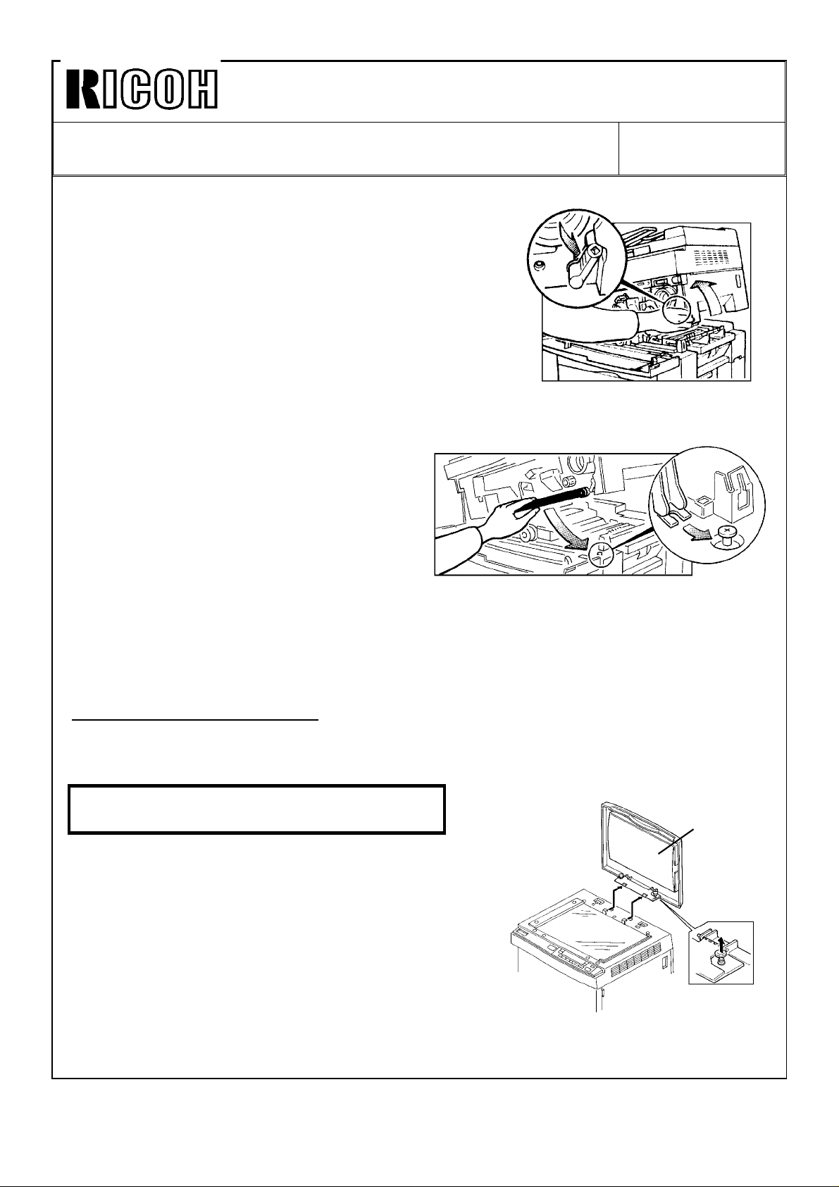
1. Remove the platen cover [A] from the copier.
2. Remove the strips of tape from the DF.
[A]
Page 6
Technical Bulletin No. RTB-003
SUBJECT: Upper Unit Problem DATE: July 15, ’92
PAGE: 3 of 4
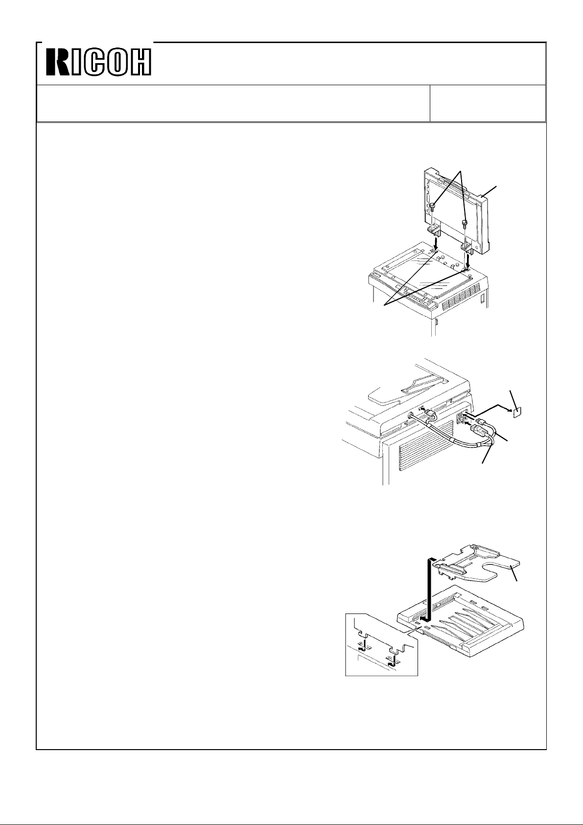
3. Insert the DF [B] into the holes [C] of the
copier upper cover.
4. Secure the DF to the copier (2 thumb screws
[D]).
5. Remove the seal [E] from the outlet of the
copier.
6. Plug in the optics fiber cable [F] to the DF and
the copier as shown.
7. Plug in the power supply cord [G] of the DF to
the outlet of the copier rear cover as shown.
[D]
[B]
[C]
[E]
[F]
[G]
8. Install the original table [H] as shown.
[H]
Page 7
Technical Bulletin No. RTB-003
SUBJECT: Upper Unit Problem DATE: July 15, ’92
PAGE: 4 of 4
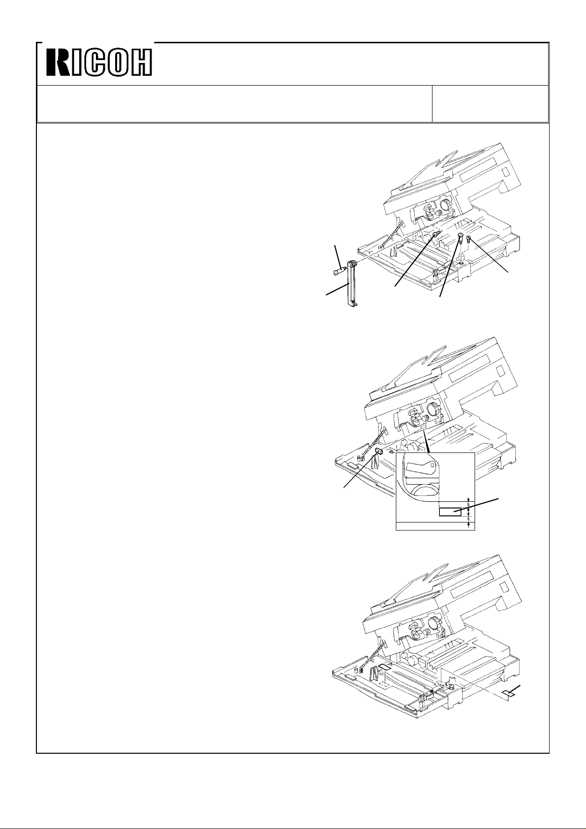
9. Open the front cover.
10. Lift the upper unit.
11. Remove 2 screws [I].
12. Tighten the shorter stepped screw [J].
13. Install the upper unit stand [K]
(1 longer stepped screw [L]).
[L]
14. Stick the magnet [M] as shown.
[K]
[M]
[I]
[I]
[J]
[M]
15. Stick the decal [N] as shown.
16. Close the upper unit and the front cover.
17. Check the operation of the DF.
18. Instruct key operators how to use the upper
unit stand.
[N]
Page 8
Technical Bulletin No. RTB-004
SUBJECT: Remarks for opening the upper unit DATE: July 15, ’92
PAGE: 1 of 1
PREPARED BY: S. Orita
CHECKED BY:
CLASSIFICATION:
Action Required
Troubleshooting
Retrofit Information
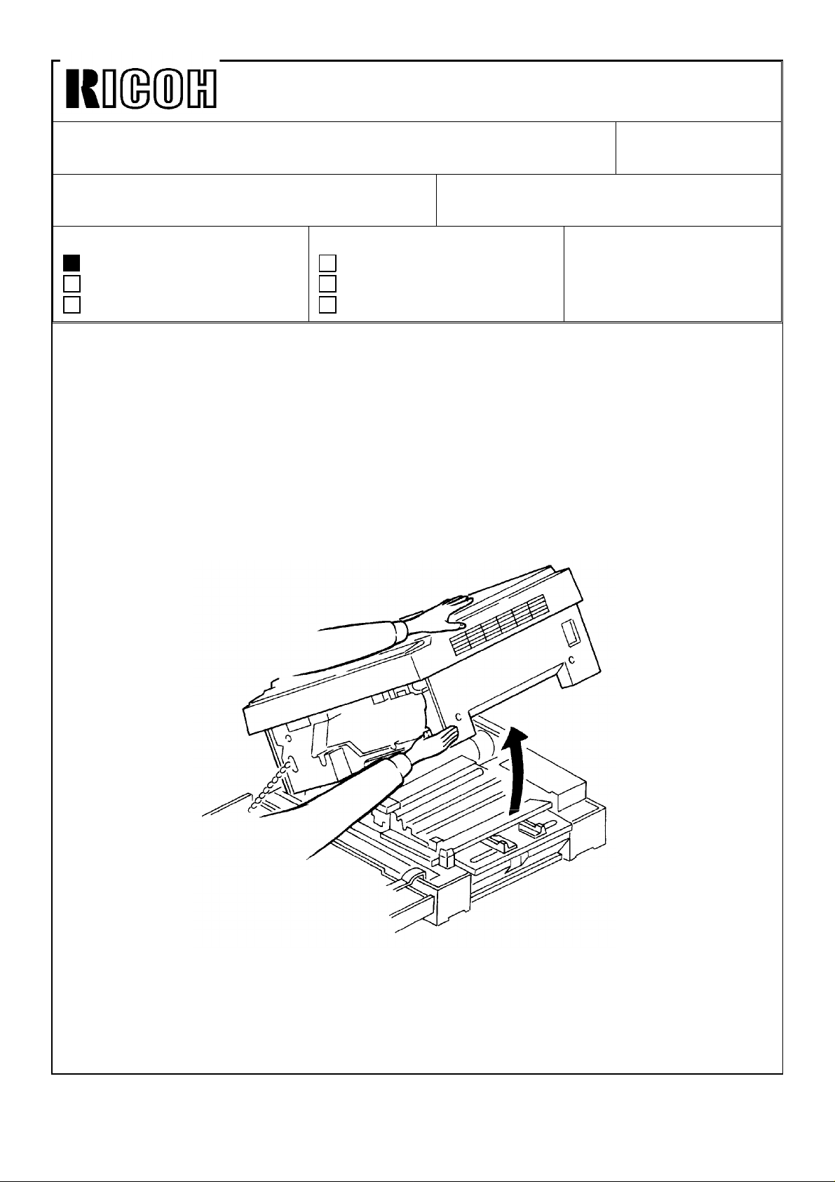
When the development unit, cleaning unit, or drum unit is removed from the machine, the
upper unit becomes lighter. If the upper unit is released under this condition, it tends to
open very abruptly. The service engineer might be injured if he is leaving over the
machine at this time. Also, the machine might move due to the shock of the upper unit
opening abruptly.
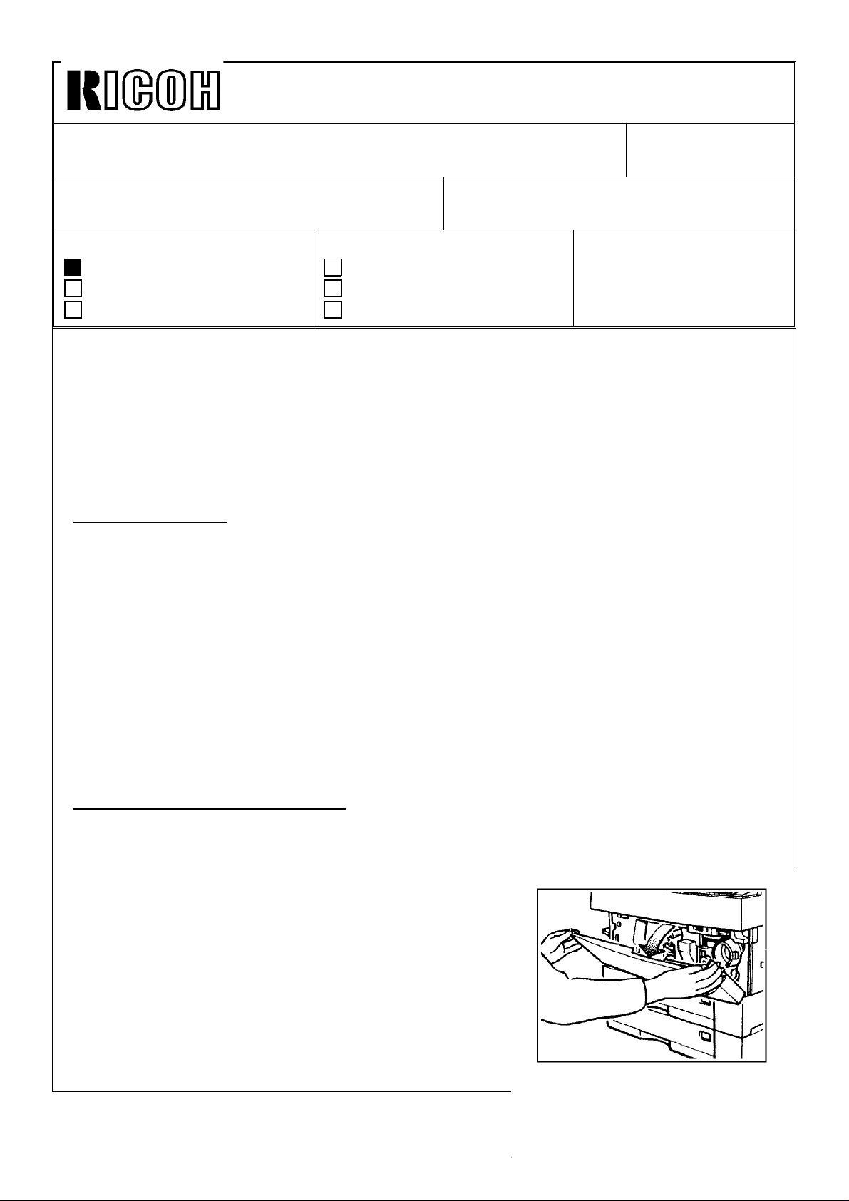
To avoid possible injury or machine damage, the service engineers should be instructed to
hold the upper unit firmly as shown in the illustration when opening the unloaded upper
unit.
Revision of service manual
Information only
Other
FROM: Copier Technical Support Section
MODEL:
E7 series
(A076/A077/A078)
Page 9
Technical Bulletin Correction Issued on: August 31, ’92
Model: E7 series (A076/A077/A078)
RTB NO: 5 Issued on: July 15, ’92 Total pages: 4
The exposure lamp data at ID level 6 is incorrect. (page 1)
The correct data is as follows:
Incorrect
Manual ID Level 123456 7
Base Bias Voltage (volts) –120 –160 –160 –160 –160 –200 –240 *Note
Exposure Lamp Data
Grid Voltage (volts)
Correct
Manual ID Level 123456 7
Base Bias Voltage (volts) –120 –160 –160 –160 –160 –200 –240 *Note
Exposure Lamp Data
Grid Voltage (volts)
Darker Lighter
Vo –4
Vg ±0
Darker Lighter
Vo –4
Vg ±0
Vo –4
Vg ±0
Vo –4
Vg ±0
Vo –2
Vg ±0
Vo –2
Vg ±0
Vo ±0
Vg ±0
Vo ±0
Vg ±0
Vo +2
Vg ±0
Vo +2
Vg ±0
Vo ±2
Vg +50
Vo +2
Vg +50
Vo +4
Vg +50
Vo +4
Vg +50
Page 10
Reissued on: August 31, ’92
Technical Bulletin No. RTB-005
SUBJECT: Service Manual Correction DATE: July 15, ’92
PAGE: 1 of 4
PREPARED BY: S. Orita
CHECKED BY:
CLASSIFICATION:
Action Required
Troubleshooting
Retrofit Information
Please correct your service manual as follows:
1. Service Manual Page 2–31 (Base Bias Voltage at ID level 5)
The correct base bias voltage at ID level 5 is 160 volts. (200 volts is incorrect.)
Please replace the first table on page 2–31 of the service manual with table below
Manual ID Level 123456 7
Base Bias Voltage (volts) –120 –160 –160 –160 –160 –200 –240 *Note
Exposure Lamp Data
Grid Voltage (volts)
Darker Lighter
Vo –4
Vg ±0
Revision of service manual
Information only
Other
Vo –4
Vg ±0
FROM: Copier Technical Support Section
MODEL:
E7 Series
(A076/A077/A078)
Vo –2
Vg ±0
Vo ±0
Vg ±0
Vo +2
Vg ±0
Vo +2
Vg +50
Vo +4
Vg +50
Vo: Exposure Lamp Data for ID level 4 (SP48)
Vg: Standard Image Grid Voltage (–680 volts)
2. Service Manual Page 2–18 (Sensing measurement for ADS mode)
(The correction is bolded)
Incorrect Correct
1. Sampling starts 10 millimeters
from the leading edge of the
original and continues for 40
millimeters from the leading edge
of original in full size mode.
2. b=
Reproduction Ratio ( %)
40 mm
x 100 2. b=
1. Sampling starts 10 millimeters
from the leading edge of the
original and continues for 50
millimeters from the leading edge
of original in full size mode.
50 mm
Reproduction Ratio ( %)
x 100
Page 11
Reissued on: August 31, ’92
Incorrect
Correct
Technical Bulletin No. RTB-005
SUBJECT: Service Manual Correction DATE: July 15, ’92
PAGE: 2 of 4
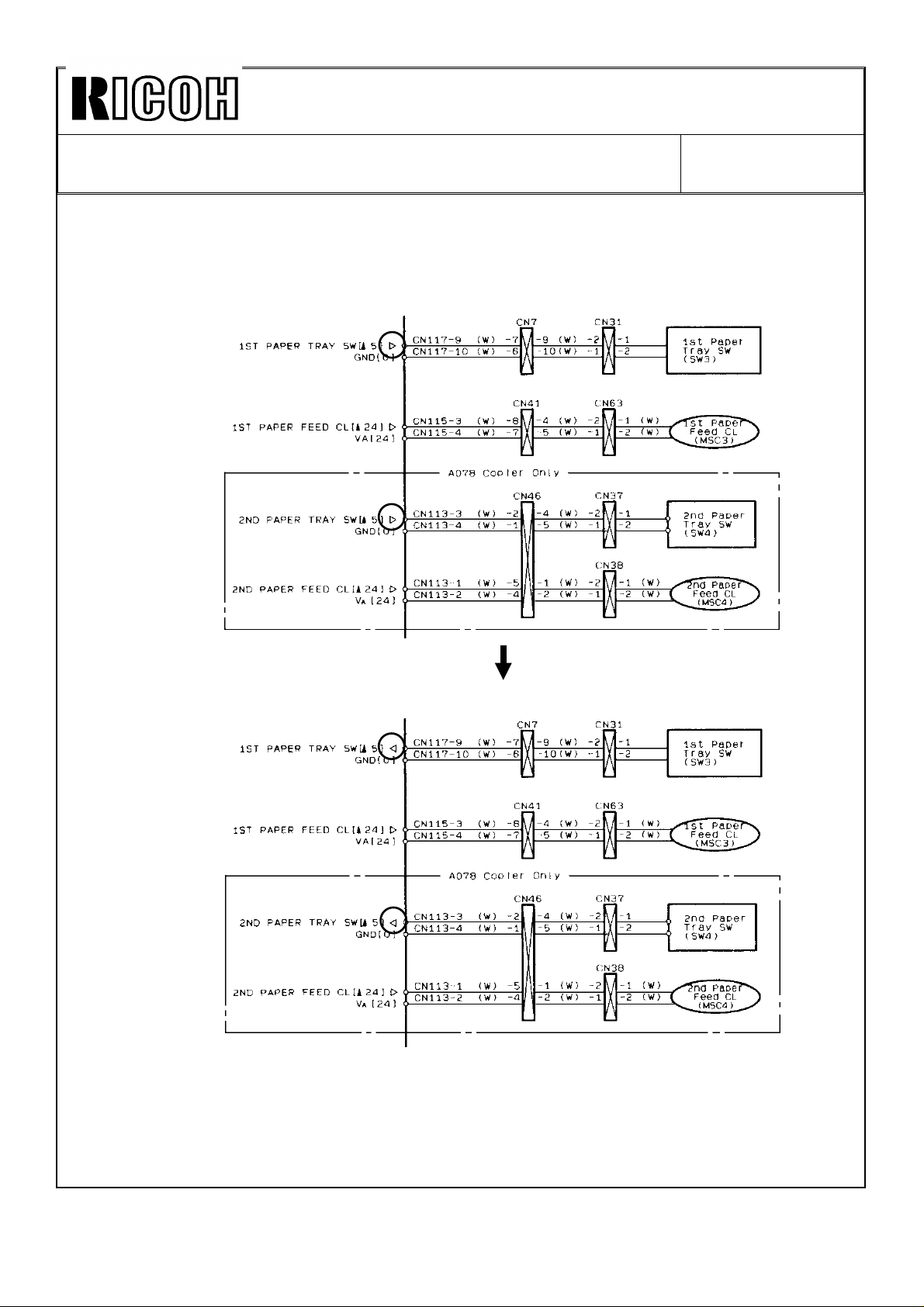
3. Service Manual – Point to Point (Directions of arrows are reversed)
(The correction is circled)
Page 12

Reissued on: August 31, ’92
Incorrect
Incorrect
Correct
Technical Bulletin No. RTB-005
SUBJECT: Service Manual Correction DATE: July 15, ’92
PAGE: 3 of 4
Correct
Page 13

Reissued on: August 31, ’92
Technical Bulletin No. RTB-005
SUBJECT: Service Manual Correction DATE: July 15, ’92
PAGE: 4 of 4
Incorrect
Correct
4. Service Manual Page 4–14 (SP111) ... A076 copier only
Please add the following explanation to page 4–14 of the service manual.
This explanation is how to use the SP111 (Number of Misfeeds by Location) for A076
copier.
1. Enter the SP mode by turning on the Dip SW101–2 on the main board.
NOTE: For A076 copier, you cannot access the SP111 if you enter the SP mode by
key operation.
2. Access to SP111.
3. Press and hold the Interrupt key.
4. Select the desired number ("1" or "2", "1" ... Paper Feed, "2" ... Exit) by the Quantity
Increase (+) or Decrease (–) key while holding the Interrupt key, and then release
the Interrupt key.
5. Press the ADS key ("111" will blink) and then press the ADS key again.
6. The first two digits for the number of misfeeds are displayed in the copy counter.
Press the Lighter key once to display the next two digits and press the Lighter key
one more time to display the last two digits (six digits in total).
Page 14

Technical Bulletin No. RTB-006
Increase
SUBJECT:
Additional Information for Exposure Lamp Voltage Adjustment
PREPARED BY: S. Orita
FROM: Copier Technical Support Section
DATE: Aug. 15, ’92
PAGE: 1 of 2
CHECKED BY:
CLASSIFICATION:
Action Required
Troubleshooting
Retrofit Information
Revision of service manual
Information only
Other
MODEL:
E7 Series
(A076/A077/A078)
It is instructed not to adjust VR401 on the service manual page 4-22.
However, if VR401 is touched by accident, it should be readjusted according to the
following procedure.
1. Remove the following covers.
•
Upper rear cover (2 screws)
•
Lower rear cover (2 screws)
•
AC drive board cover (2 screws)
2. Enter SP51 and c heck whet her the
exposure lamp data becomes "126" or
not .
If yes, go to step 3.
If no, exit SP51 and enter SP48. Adjust
the SP48 data using the Increase (+) or
Decrease (–) key to display 126" in
SP51, then exit SP48.
3. Turn off the main switch.
4. Set the multimeter range to ac 200 V and
connect the multimeter leads to CN419-1
and CN419-2 on the ac drive board as
shown.
5. Turn on the main switch and enter SP51.
6. Adjust the exposure lamp output voltage
to the following voltage by turning VR401.
115 V machine ............................ 72 volts ac (r.m.s.)
220 ∼ 230/240 V machine ......... 134 volts ac (r.m.s.)
Decrease
Page 15

Technical Bulletin No. RTB-006
SUBJECT:
Additional Information for Exposure Lamp Voltage Adjustment
7. Press the Clear/Stop key.
8. Enter SP95 and set "1" to reset the exposure lamp data for the VL correction.
9. Perform the Light Intensity Adjustment. (See service manual page 5-82.)
NOTE: The exposure lamp voltage can be adjusted by SP48.
Shifting SP48 by one will shift the voltage as follows:
115 V machine ............................. about 0.5 volt
220 ~ 230/240 V machine .......... about 1 volt
However, if VR401 is not adjusted properly, this voltage shift is changed. As a
result, the exposure lamp corrections (VL correction, VR correction, drum
temperature correction, reproduction ratio correction) will not function properly.
DATE: Aug. 15, ’92
PAGE: 2 of 2
Page 16

Copy paper
Copy image
Reissued on Dec. 15 ’92
Technica l Bulletin No . RTB-00 7
SUBJECT: Tro ub lesho ot ing for t he b ent imag e and /o r s kewed imag es. DATE: Oct. 15 ’92
PAGE: 1 of 10
PREPARED BY: S. Or ita
CHECKED BY:
CLASSIFICATION:
Action Required
Troubleshooting
Retrofit Information
The b ent im age and / or sk ewed imag es app ear o n c o pies as fo llow s:
Phenomenon: 1) Bent im age
The b ent imag e ap p ear s at aro u nd 50 m m fr o m t he t railin g e dg e o f
copy paper as shown.
Paper feed
direction
Revision of service manual
Information only
Other
FROM: Copier Technical Support Section
MODEL:
E7 ser ies
(A076/A077 c op ier)
aro und 50 m m
RearFro n t
2) Paper sk ewing
The rear side of the copy paper feeds ahead of the front side, and
skew ed imag es ap p ear o n c op ies as sh ow n.
Paper feed
direction
Vertical lines on the copy image ar e not par allel to th e
edge of the copy paper.
RearFront
In addition, when paper skewing appears as described above, lines also
may b e b ent at aro un d 50 m m fr om the t railin g ed g e of t he c op y p ap er.
Page 17

Reissued on Dec. 15 ’92
Technica l Bulletin No . RTB-00 7
SUBJECT: Tro ub lesho ot ing for t he b ent imag e and /o r s kewed imag es. DATE: Oct. 15 ’92
PAGE: 2 of 10
3) Optical skewing
Parallelogr am sk ewed im ages app ear on c op ies as sho wn .
Copy paper
Copy image
Paper feed
direction
Vertical lines on the copy image ar e parallel to the ed ge
the copy paper.
Cause: 1) Bent imag e
The front side fusing pressure lever does no t move up and d own
smoothly and/or the paper feed unit position is not parallel to the OPC
drum position.
2) Paper sk ewing
The paper feed unit position is not parallel to the OPC drum position.
3) Optical skewing
The 4th/5th mirror position is not parallel to the OPC drum position.
Page 18

a
< Rear>
Reissued on Dec. 15 ’92
Technica l Bulletin No . RTB-00 7
SUBJECT: Tro ub lesho ot ing for t he b ent imag e and /o r s kewed imag es. DATE: Oct. 15 ’92
PAGE: 3 of 10
Solution: 1) Bent imag e
When checking the copy image during the installation, confirm that the
developer initial setting (SP65) has been properly performed.
1. Open t he exit c over .
2. Reposition the front and rear pressure springs [A and B] from "b"
to "a" a s s ho w n b el o w.
c
a
b
[A]
< Front>
3. Close the exit cover.
4. Open the upper unit.
5. App ly t he Mo b il Temp 78 to th e area b etween th e fro nt s ide fu sing
pressure lever [ C] and fusing unit side frame as shown below.
CAUTI ON: M a ke sure no t to b end the lever.
c
b
[B]
Mo b il Temp 78
[C]
6. Close the upper unit and check the copy quality.
NOTE: If t he ben t imag e still app ears , c heck fo r pap er s kewin g an d
perform the procedure in this RTB on page 4 to 9.
Page 19

Less th an 1.5 m m
Reissued on Dec. 15 ’92
Technica l Bulletin No . RTB-00 7
SUBJECT: Tro ub lesho ot ing for t he b ent imag e and /o r s kewed imag es. DATE: Oct. 15 ’92
PAGE: 4 of 10
2) Paper sk ewing
Specification: Less than 1.5 mm against a length of 200 mm
Before checking the copy image, confirm the following items.
1. The co pier is plac ed o n a flat t able.
2 . The le adin g ed ge o f the o rig inal is alig ned wit h the le ft sc ale.
3. When the copy paper is loaded into the paper tray, confirm that
the front, rear, and end guides of the paper tray securely hold the
paper.
Ch eck that the c op y imag e is wit hin sp ecific atio n as sh ow n:
Paper feed
direction
Copy paper
Copy image
"A"
200 mm
"B"
Page 20

[C]
Reissued on Dec. 15 ’92
Technica l Bulletin No . RTB-00 7
SUBJECT: Tro ub lesho ot ing for t he b ent imag e and /o r s kewed imag es. DATE: Oct. 15 ’92
PAGE: 5 of 10
– M ethod A –
1. Turn off the main switch and unplug
the power supply cord.
2. Remove the DF if installed.
3. Remove the paper tray.
4. Op en t he fr on t c o ver.
5. Open the upper unit by pushing the
release lever .
6. Remove the harness cover [A]
(2 screws).
7. Remove the lower rear cover
(2 screws).
8. Loos en the two front screws [ B] and
one rear screw [C] securing the
paper feed unit [D].
[A]
[B]
[D]
Page 21

[G]
Drum Unit
side
Reissued on Dec. 15 ’92
Technica l Bulletin No . RTB-00 7
SUBJECT: Tro ub lesho ot ing for t he b ent imag e and /o r s kewed imag es. DATE: Oct. 15 ’92
PAGE: 6 of 10
9. Adjust the paper feed unit position
as follows:
a) Tighten the screw [E] while
pushing the rear side of the paper
feed u nit to the m anual feed side
as shown.
[E]
b) Tighten the screw [ F] while
pushing the front side of the paper
feed unit to the drum unit side as
shown. Then, tighten the other
screw [ G] .
< Rear side of the paper feed unit>
< Front side of the paper feed unit>
10. Reinstall all covers and units.
11. Check the copy quality.
NOTE: When pap er sk ewin g is c or rec ted , the b ent im age at ar ou nd 50 m m fro m t he
If the finer adjustment is required, follow method B.
[F]
trailin g edg e is als o c o rre ct ed.
Page 22

Reissued on Dec. 15 ’92
Technica l Bulletin No . RTB-00 7
SUBJECT: Tro ub lesho ot ing for t he b ent imag e and /o r s kewed imag es. DATE: Oct. 15 ’92
PAGE: 7 of 10
– M ethod B –
1. Follow steps 1 to 7 o f met hod A.
2. Remove the DC power supply unit
[ A] (4 screw and all connectors).
3. Remove three clutch connectors [B].
4. Remove t he r ear sid e p late [C]
(4 screws, 6 wire clamps and 1
connector).
5. Remove the timing belt tightener [ D]
(1 spring [ E]).
[B]
[A]
[D]
[E]
[C]
Page 23

[H]
[I]
[K]
Reissued on Dec. 15 ’92
Technica l Bulletin No . RTB-00 7
SUBJECT: Tro ub lesho ot ing for t he b ent imag e and /o r s kewed imag es. DATE: Oct. 15 ’92
PAGE: 8 of 10
6. Take off the main motor belt [F]
from the pulley.
7. Remove two connectors [G] from
the paper feed unit [ H].
8. Remove the paper feed unit (4
screws).
9. Cut and file the front po sitioning pin
[ I] of the paper feed unit.
NOTE: File the front positioning pin
until it is even with the botto m
plate [J] .
[F]
[G]
[I]
[J]
10. File the front screw holes [K] o f the
pap er feed unit as s ho wn.
[J]
2 mm
Page 24

Manual
Feed sid e
Drum Unit
side
Reissued on Dec. 15 ’92
Technica l Bulletin No . RTB-00 7
SUBJECT: Tro ub lesho ot ing for t he b ent imag e and /o r s kewed imag es. DATE: Oct. 15 ’92
PAGE: 9 of 10
11. Install the paper feed unit as follows:
a) Secure the screw [L] while
pushing the rear side of the paper
feed u nit to the m anual feed side
as shown. Then, secure the other
screw [ M].
b) Secure the screw [ N] while
pushing the front side of the paper
feed unit to the drum unit side as
shown. Then, secure the other
screw [ O] .
< Rear side of the paper feed unit>
[M]
[L]
< Front side of the paper feed unit>
NOTE: When sliding the front side of
the paper feed unit to the drum
unit side, make sure that the
paper feed unit does not
overlap the screw [ P] securing
the ear th p late.
12. Reinstall all covers and units.
13. Check the cop y quality. If the paper now skews in the opposite direction (front side of
cop y paper feeds ahead), push the front side of the paper feed unit to the manual feed
side. Check & repeat the procedure until the skew is corrected.
[P]
[N]
[O]
Page 25

Reissued on Dec. 15 ’92
Technica l Bulletin No . RTB-00 7
SUBJECT: Tro ub lesho ot ing for t he b ent imag e and /o r s kewed imag es. DATE: Oct. 15 ’92
PAGE: 10 of 10
If the horizontal lines on the copy image are not parallel to the edge of the copy paper,
follow the adjustment for optical skewing.
3) Optical skewing
Adjust the 4th/5th mirror height.
(This adjustment is described in the service manual on page 5-95.)
NOTE: This adjustment should be performed after the vertical lines on the copy image
are parallel to the edge of the copy paper.
Page 26

Technica l Bulletin No . RTB-00 9
SUBJECT: Software Modification DATE:
Apr. 15, 1993
PAGE: 1 o f 2
PREPARED BY: S. Or ita
CHECKED BY:
CLASSIFICATION:
Action Required
Troubleshooting
Retrofit Information
Becau se o f softw are c hang es, the ROM has b een ch ang ed fr om P/N A0775105 to P/ N
A0775105A.
The det ails of s oft ware c hang es ar e as follo ws :
1. Up pe r limit fo r VL correction
Old ROM (R/N A0775105)
1) SP48 data up t o"150" co uld be ent ered.
2) VL correction was applied until the exposure lamp data (SP51) reached its maximum
of "145".
New ROM (P/N A0775105A)
1) SP48 data up to "145" can be en tered .
Revision of service manual
Information only
Other
FROM: Copier Technical Support Section
MODEL: E7 Series
(A076/A077)
2) VL correction is applied until its maximum of + 20.
If "140" is entered in SP48, VL correction is applied until "160".
Note: The total corrections for the exposure lamp (VL correction + VR correction +
Drum temperature correction + Reproduc tion ratio correction) are applied until
170. (This is the same as that of the old ROM.)
2. New procedure for accessing of SP111 (Number of misfeeds by location) -- A076
copier only.
The p revio us ac c ess p r oc ed ur e of SP111 for the A076 c o pier is exp lained in E7 RTB No. 5.
The following procedure can be used with the new ROM (The previous procedure can
also be used with the new ROM).
1) Enter the SP mode by key operation.
2) Acc ess to SP111.
Note: It is neces sary to tur n o n DIP SW 101-2 to acc ess SP111 with the o ld ROM.
3) Select the d esired num ber ( "1" or "2", "1" --- Paper feed, "2" --- Exit) by t he Quant ity
Increase (+ ) or Decrease (–) k eys.
4) The first two digits for the number of misfeeds are displayed in the copy counter.
Press the Lighter key once to display the next two digits and press the Lighter key
one more time to display the last two digits (six digits in total).
Page 27

Technica l Bulletin No . RTB-00 9
SUBJECT: Software Modification DATE:
Apr. 15, 1993
PAGE: 2 o f 2
3. Blurred image problem with ADF in the interrupt mode
( Pheno me non) When making the A4 lengthwise copies with the ADF in the interrupt
mo de, a blu rr ed im age app ear s on co p ies at 20 mm fr o m th e trailin g edg e
(Case) Due to a software problem, the DF motor is energized before the
pr evio us o rig inal s ca nnin g is co mp let ed.
( Solution) The software has been changed so that the DF motor is energized after the
pr evio us o rig inal s ca nnin g is co mp let ed.
The cu t-in ser ial numb ers for t he new ROM (A0775105A) are as fo llows :
M achine Code
A076-10 291303XXXX
A076-15 3021000001
A076-16 2913010001
A076-17 A2942101135
A076-19 A294303XXXX
A076-22 2902100001
A076-25 2902100140
A076-26 3B71020001
A076-27 A2942100001
A076-28 A2943030569
A076-29 A2942100841
A077-10 2933010001
A077-15 5121000001
A077-16 2932110001
A077-17 A2952100001
A077-19 A295303XXXX
A077-22 2922100001
A077-25 2922100152
A077-26 3B81020001
A077-27 A2952100381
A077-28 A2953032013
A077-29 A2952100991
Cut-in Serial
numbe r
Page 28
Technica l Bulletin No . RTB-01 0
SUBJECT: Constant J1 Misfeed Problem DATE:
May 15, 1993
PAGE: 1 o f 1
PREPARED BY: S. Or ita
CHECKED BY:
CLASSIFICATION:
Action Required
Troubleshooting
Retrofit Information
Phenomenon: The leading edge of the copy paper always stops around the feed and
torque rollers area.
Cause: During copying, the diameters of the torque and paper feed rollers decrease
gradually in proportion to the number of the papers fed.
As a result, the torque roller does not rotate together with the paper when
one copy paper feed s. One part of the torque roller surface gets worn out
and J1 misfeed s oc cu r.
Solution: The inner d iamet er o f th e slip c lutc h s pr ing h as b een d ec reas ed fro m
15.80 mm to 15.84 mm so that the slip torque of the slip clutch is
decreased (refer to E7 MB No. 8).
As a result, the amount of decrease of the feed roller diameter has been
smaller and the expected lifetime of the torque roller is now mo re than 80 K
copies.
Revision of service manual
Information only
Other
FROM: Copier Technical Support Section
MODEL: E7 Series
(A076/A077)
The servic e manu al mentio ns that t he to rq ue ro ller sh ould b e rep laced at every 160 K
co pies . We have fou nd t hat t he expec ted lifetime o f this r oller d o es no t reac h 160 K
copies even after the above modification is applied.
The PM interval for the torque roller should be changed to 80 K copies.
Please cor rec t yo ur ser vice man ual as follo ws: (Page 4-29)
ITEM EM 80 K 160 K NOTES
Tor qu e Roller C R R Water
R= Replac e C= Clean
Page 29

Technical Bulletin No. RTB-011
SUBJECT: Software Modification DATE: Sep. 30, ’93
PAGE: 1 of 2
PREPARED BY: S. Orita
CHECKED BY:
CLASSIFICATION:
Action Required
Troubleshooting
Retrofit Information
Because of software changes, the ROM has been changed from P/N A0775105A to
P/N A0775105B.
The details of the software changes are as follows:
1. Coin rack enable
(Phenomenon)
Coin rack cannot be used.
(Cause)
With the old ROM (P/N A0775105A), if you remove the key counter from the copier before
the end of the copy cycle, the machine immediately stops and a paper misfeed might
occur. This is to prevent the key counter from being removed before the key counter
counts up.
For the above reason, a coin rack cannot be used with the old ROM.
Revision of service manual
Information only
Other
FROM: Copier Technical Support Section
MODEL: E7 Series
(A076/A077)
(Solution)
At the field’s request, the ROM has been changed to permit use the coin rack.
According to this change, the machine can be set so that no paper misfeed occurs even if
the key counter is removed from the copier during the copy cycle. However, if the key
counter is removed before the paper reaches the registration sensor, the key counter does
not count up.
When installing the new ROM to machines on which customers request using the coin
rack, change SP 22 data from "0" to "1 as follows:
(SP 22 is a new SP mode.)
Mode Number Function
SP22 Coin Rack Enable 0: Not used the coin rack (Factory setting)
1: Enables coin rack operation
Page 30

Technical Bulletin No. RTB-011
SUBJECT: Software Modification DATE: Sep. 30, ’93
PAGE: 2 of 2
2. Malfunction for F size detection
(Phenomenon) When making F size (81⁄2" x 13") copies, a blank image appears on copies
at the trailing edge.
(Cause) Due to a software problem, the F paper size is detected as A4 paper size.
(Solution) The software has been changed so that the F paper size is detected
properly.
The cut-in serial numbers for the new ROM (A0775105B) are as follows:
Machine Code
A076-10 291309XXXX
A076-15 303090XXXX
A076-16 2913070001
A076-17 A294309XXXX
A076-19 A294309XXXX
A076-22 2903080001
A076-25 2903060050
A076-26 3B7 083000 1
A076-27 A29430700 01
A076-28 A29430600 01
A076-29 A29430600 21
A077-10 2933040081
A077-15 5130500001
A077-16 2933040001
A077-17 A29530401 96
A077-19 A295309XXXX
A077-22 2923040001
A077-25 2923040028
A077-26 3 B8093X XXX
A077-27 A29530702 01
A077-28 A29530608 01
A077-29 A29530407 76
Cut-in Serial
number
Page 31

Reissued on March 31 ’94
Technical Bulletin No. RTB-012
SUBJECT: Off-set Image Problem DATE: Dec. 31, ’93
PAGE: 1 of 2
PREPARED BY: S. Orita
CHECKED BY:
CLASSIFICATION:
Action Required
Troubleshooting
Retrofit Information
(Phenomenon)
Toner sticks to the hot roller and then is transferred to the copy paper from the hot roller
forming an off-set image.
(Cause)
This problem may or may not occur depending on the type of copy paper used. If the dust
from the copy paper contains a large amount of calcium carbonate, it tends to adhere to
the graphite in the teflon layer of the hot roller. If that happens toner sticks and gradually
accumulates at the same place on the hot roller. The greater the amount of the calcium
carbonate containing the copy paper, the more easily the toner sticks to the hot roller.
(Solution)
It is difficult to control the type of paper used and more kinds of paper including recycled
paper, which contains more additives, will be used in the future. Therefore, we have
decided to remove the graphite from the hot roller in order to expand the tolerance to
paper types and reduce the toner sticking problem.
The cut-in serial number of this change is as follows:
Revision of service manual
Information only
Other
FROM: 2nd Technical Support Section
MODEL: E7 series
(A076/A077)
Machine Code Cut-in Serial
Number
A076-10 2913110001 A077-10 2933100001
A076-15 3030110001 A077-15 5131000001
A076-16 2913100001 A077-16 2933100021
A076-17 A2943100001 A077-17 A2953100151
A076-19 A2944010426 A077-19 A295403XXXX
A076-22 2903100001 A077-22 2923120001
A076-25 2903100424 A077-25 2923100001
A076-26 3B71030001 A077-26 3B81030001
A076-27 A2943100348 A077-27 A2953110001
A076-28 A2943121414 A077-28 A295403XXXX
A076-29 A2944010625 A077-29 A2953100021
Machine Code Cut-in Serial
Number
Page 32

Reissued on March 31 ’94
Technical Bulletin No. RTB-012
SUBJECT: Off-set Image Problem DATE: Dec. 31, ’93
PAGE: 2 of 2
(How to distinguish the new hot roller from the old one)
The part number of the hot roller has not been changed (only a suffix change).
To distinguish the new hot roller from the old one, a red mark or an extra groove has been
added to the rear edge of the new hot roller as shown.
The new hot roller has been stocked in SPC since the end of August.
New Hot Roller
C-ring groove
A red mark or an
extra groove has
been added here.
Rear
Page 33

Technical Bulletin No. RTB-013
SUBJECT: Remarks for replacing the fusing thermoswitch DATE:
January. 31, 1994
PAGE: 1 of 2
PREPARED BY: S. Orita
CHECKED BY:
CLASSIFICATION:
Action Required
Troubleshooting
Retrofit Information
We have been informed that some field technicians might not have installed the fusing
thermoswitch bracket properly. As a result, service code #E52 may be displayed because
of an incorrect gap between the thermoswitch and the hot roller.
To prevent this, a note on thermoswitch bracket installation has been added to the
"FUSING THERMOSWITCH REPLACEMENT" procedure. Please correct your service
manual p age 5-77 .
Service Manual (Page 5-77)
7.6 FUSING THERMOSWITCH REPLACEMENT
[C]
[B]
Revision of service manual
Information only
Other
FROM: 2nd Technical Support Section
MODEL: E7 Series
(A076/A077)
[D]
[C]
[A]
1. Turn off the main switch and unplug the power supply cord.
2. Open the front cover.
3. Remove the upper inner cover (3 screws).
4. Remove the drum unit. (See Drum Replacement.)
5. Hold down the top of upper unit and open the upper unit by pushing the release lever.
Page 34

Technical Bulletin No. RTB-013
SUBJECT: Remarks for replacing the fusing thermoswitch DATE:
January. 31, 1994
PAGE: 2 of 2
6. Remove the fusing cover [A] (1 screw).
7. Remove the thermoswitch bracket [B] (1 screw).
8. disconnect two thermoswitch connectors [C].
9. Remove the thermoswitch [D] from the bracket (2 screws).
NOTE:
When installing the thermoswitch bracket [E], make sure that the projection [F] on the
thermoswitch bracket enters into the hole [G] on the fusing unit frame [H].
[G]
[F]
[E]
[H]
This is newly added
Page 35

Technical Bulletin No. RTB-014
SUBJECT: Off-set Image Problem (a final countermeasure) DATE: Nov. 15, ’94
PAGE: 1 of 1
PREPARED BY: S. Orita
CHECKED BY: S. Hamano
CLASSIFICATION:
Action Required
Troubleshooting
Retrofit Information
As mentioned in the RTB No.12, the greater amount of Calcium Carbonate the copy paper
contains, the more easily the toner sticks to the hot roller.
It is difficult to control the type of paper which is used in the field. Besides, paper
containing more additives seems to be more popular in the future.
Therefore, we decided to remove the graphite from the hot roller last year to reduce the
toner sticking problem. (P/N AE011009B → C)
To further increase the tolerance to the problem, this time, we have changed the kind of
Teflon coating of the hot roller. With this change, pin holes on the hot roller surface which
hook the mixture of toner particles and paper additives, have been reduced and the roller
surface has become more smooth.
Old P/N New P/N Description
AE011009 AE011033 Hot Ro ller
Revision of service manual
Information only
Other
FROM: 2nd Technical Support Section
MODEL:
E7 series
(A076 / A077)
On the other hand, the material change lowers the hardness of the new hot roller, which
forces to shorten the present 160,000-copy PM cycle to the new 80,000-copy PM cycle.
Item EM 80K 160K
Hot Roller I I or R I or R
I: Inspection R: Replace
The new hot roller has been installed in the Robin copier since the first production.
The E7 Copier is no longer produced. The new hot roller is available for the E7 as a
spare part.
 Loading...