

Page 1
Technical Bulletin No. RTB-001
SUBJECT: Paper lift and sector gear slipping DATE: Sep. 15, ’91
PAGE: 1 of 1
PREPARED BY: T. Itoh
CHECKED BY:
CLASSIFICATION:
Action Required
Troubleshooting
Retrofit Information
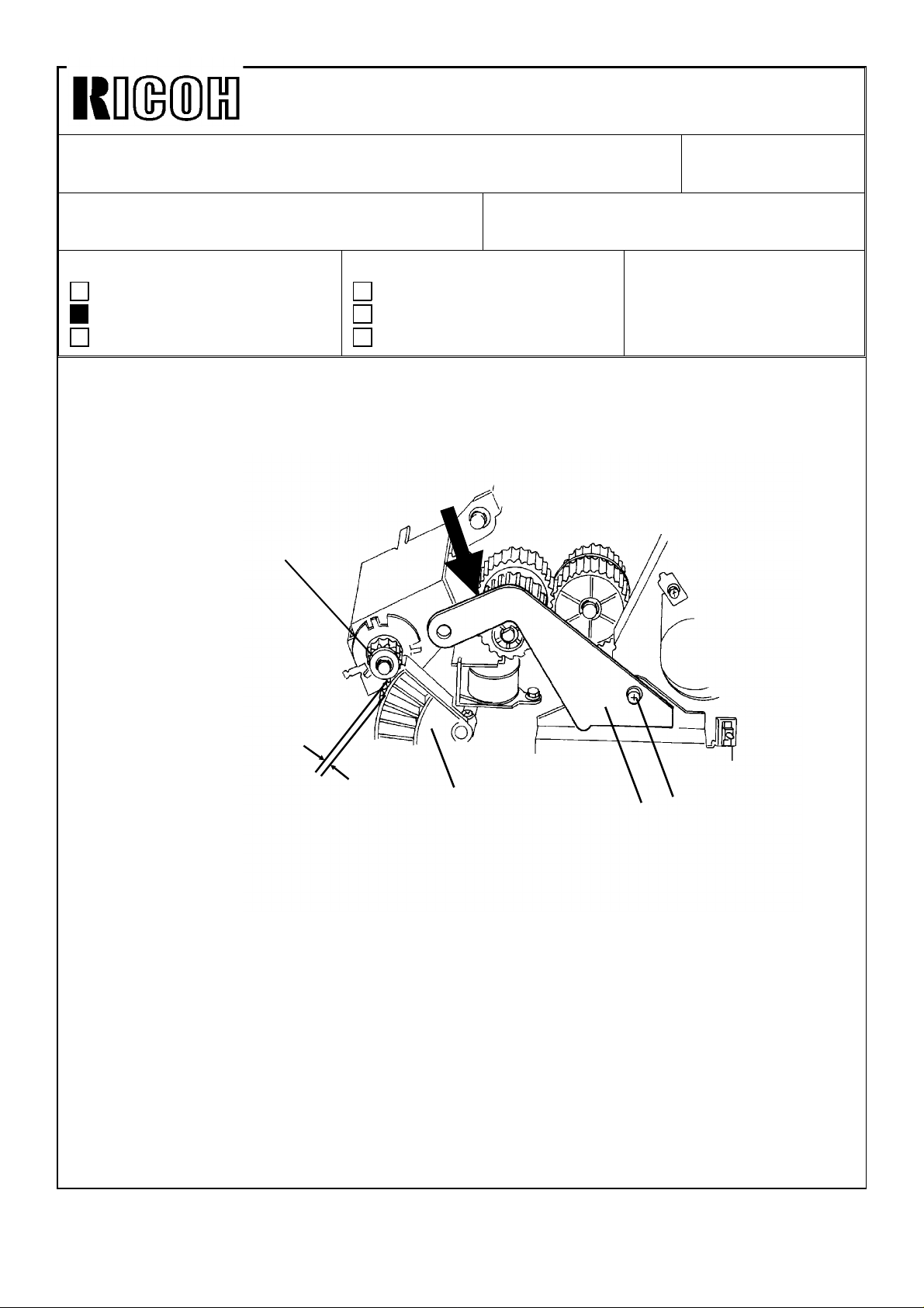
[ Phenomenon ] When the paper stack in the cassette is lifted up, the paper lift
gear [A] and the sector gear [B] slip.
[ Cause ] The mesh between the paper lift gear and the sector gear is too
shallow.
[ Action ]
[A]
Revision of service manual
Information only
Other
Push
TO: Copier Technical Support Section
MODEL: N210
No Gap
1. Turn off the main switch.
2. Make sure that the cassette is installed on the copier and the manual feed table is
closed.
3. Remove the rear cover and the main board.
4. Loosen the screw [C].
5. Retighten the screw while pushing down the paper lift clutch support bracket [D] so
that there is no gap between the pitch circles of the paper lift gear and the sector gear.
6. Reassemble all parts previously removed.
NOTE: When the paper lift clutch support bracket is removed during servicing, the
bracket must be reinstalled according to the above procedure.
[B]
[D]
[C]
Page 2
Technical Bulletin
No.
RTB-002
SUBJECT: New procedure for the DG (doctor gap) adjustment
PREPARED BY:
CHECKED BY:
CLASSIFIC
FROM: Copier Technical Support Section
MODEL: N210
DATE: Jan. 31, ’92
PAGE: 1 of 4
■ Revision of service manual
❑ Information only
❑ Retrofit Information ❑ Other
This procedure supersedes the doctor gap adjustment procedure in the service manual.
NEW PROCEDURE:
CAUTION: The doctor gap was adjusted at the factory using the special
tool. Therefore, normally this adjustment is not required in the field.
Only when the development unit is disassembled or the development
roller is replaced, this adjustment is required.
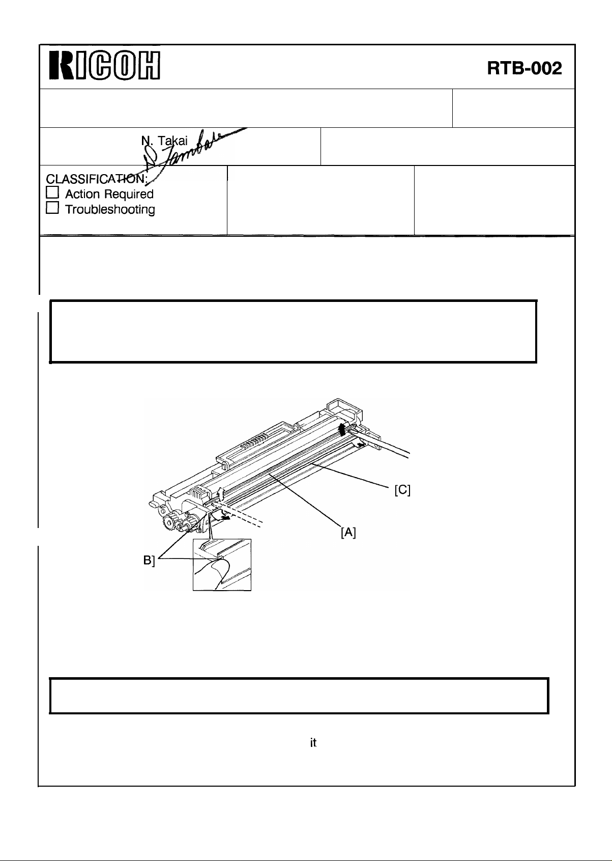
1. Confirmation Procedure
[
1. Take out the development unit.
2. Remove the developer.
3. Remove the inlet seal plate [A] by working a small blade screwdriver along the edge of
the plate while pressing the stoppers [B] with one finger as shown.
CAUTION: Be careful not to damage the stoppers [B] when removing the inlet seal
plate.
4. Clean the development roller [C] with a vacuum cleaner until no developer is left on
it
the roller. Turn the roller to make sure that
NOTE: This prevents surface damage to the roller and ensures an accurate adjustment.
is free of developer.
Page 3

Technical Bulletin
No.
RTB-002
SUBJECT: New procedure for the DG (doctor gap) adjustment
20 mm
DATE: Jan. 31, ’92
PAGE: 2 of 4
Position the DG gauge (P/N #A0489507) 20 mm (0.8 inch) from the front end of the
5.
development roller, and insert the gauge into the doctor gap until it stops.
‘
CAUTION: Do not force the DG gauge into the gap and do not press the gauge too
hard on the roller. The roller should not rotate when you insert the
gauge into the gap.
I
Page 4
Technical Bulletin
No.
RTB-002
SUBJECT: New procedure for the DG (doctor gap) adjustment
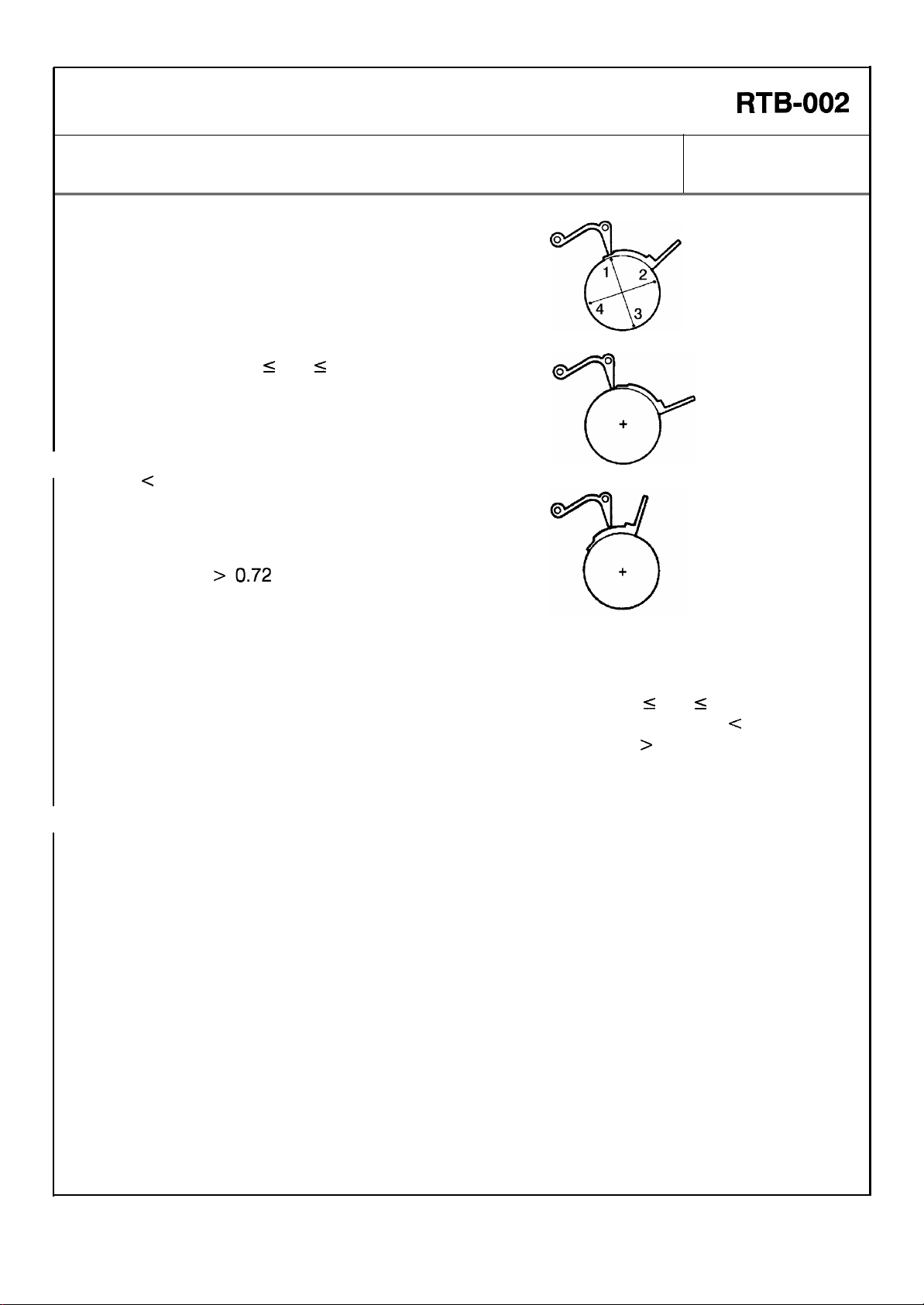
6. Check the doctor gap at four points
turning the development roller 90° each
time.
If the “GO” part of the DG gauge goes
through the doctor gap, and the “NO GO”
part does not go through, the gap at this
s
point is: 0.63 mm
If the “GO” part of the DG gauge does not
go through the doctor gap, the gap at this
point is:
c
0.63 mm
DG
If both “GO” part and “NO GO” part go
through the doctor gap, the gap at this
point is: DG
>0.72
DG s 0.72 mm
mm
DATE: Jan. 31, ’91
PAGE: 3 of 4
Good
Too narrow
Too wide
7. Repeat steps 6 and 7 for the rear side of the development roller.
s
8. If either 3 out of 4 checked points or all 4 points are “0.63 mm
gap is in good condition. If more than 2 out of 4 checked points are “DG
adjust the DG. If more than 2 out of 4 checked points are “DG
DG only when there is any of the following problems:
a. Severe jitter copy
b. Blocking of development drive mechanism
c. Developer leakage
DG s 0.72 mm”, the
> 0.72 mm” adjust the
e
0.63 mm”,
Page 5

Technical Bulletin
No. RTB-002
SUBJECT: New procedure for the DG (doctor gap) adjustment
2.
Adjustment Procedure
Adjustment standard :0.63 <= DG <= 0.72
DATE: Jan. 31, ’92
PAGE: 4 of 4
CAUTION: Before adjusting the doctor gap, the confirmation procedure must be
performed.
1
Go
1. Clean the development roller [A] with a vacuum cleaner until no developer is on the
roller. Turn the roller to make sure that it is free of developer.
2. Loosen the doctor plate [B] (4 screws).
3. Insert the “NO GO” part of the gauge [C] in the doctor gap 20 mm from the front side
of the development roller as shown.
NOTE: The front side should be adjusted first to prevent the doctor gap from being too
narrow.
4. Press down the doctor plate directly above the gauge, and tighten the front doctor
pIate screws [D].
NOTE: Do not press the doctor plate too hard, the doctor gap will become too narrow.
5. Repeat the adjustment procedure at the rear side of the development roller.
6. Confirm that the doctor gap is adequate by following the confirmation procedure.
Page 6

REVISED ON SEPTEMBER 30, ’93
Technical Bulletin No. RTB-003
SUBJECT: Lubrication of the idle gear and the idle gear shaft. DATE:
Feb. 28, 1 993
PAGE: 1 of 2
PREPARED BY: N. Takai
CHECKED BY:
CLASSIFICATION:
Action Required
Troubleshooting
Retrofit Information
A rattling noise comes out from the idle gear engagement or jitter images appear about
100 K to 150 K copies after machine installation. This is because the shaft of the idle
gear-35 Z (P/No. AB013434) is being worn out gradually and the gear engagement
becomes poor.
To prevent this problem, the gear shaft and the gear’s teeth should be lubricated at your
next visit, and the gear teeth at every PM interval afterwards, according to the following
procedure:
- Action required -
Revision of service manual
Information only
Other
FROM: Copier Technical Support Section
MODEL: N210
1. Remove the rear cover (4 screws).
2. Remove the fusing drive release
spring [A].
3. Remove the main motor ass’y [B]
(4 screws and 1 connector)
[A]
[B]
Page 7

Technical Bulletin No. RTB-003
SUBJECT: Lubrication of the idle gear and the gear shaft. DATE:
Feb. 28, 1 993
PAGE: 2 of 2
4. Remove the E-ring [C] and the washer
[D] from the idle gear shaft.
5. Lubricate the gear’s teeth with Grease
G-501 [E] and the gear shaft with the
spindle oil [F].
[D]
6. Reassemble.
[F]
* Confirm that the fusing drive release
spring [A in page 1] is set. If this
spring is not set, drive cannot
transmitted to the fusing section.
NOTES: (1) For the field machines having this problems, we recommend replacing the idle
gear with the modified one (new P/No. AB013841). (Refer to M/B # 15. )
(2) When the modified gear is installed, the two washers (P/No. 52031870 [G] and
08075074 [H]) should be installed together in the order illustrated.
* Since the modified gear has ball-bearings inside instead of dry-bearings, this
gear works even if the shaft is worn out.
[C]
[E]
[H]
[G]
Page 8

Technica l Bulletin No . RTB-00 4
[C]
SUBJECT: N o m an ual fee d o p er atio n DATE: Ap r il 30, ’93
PAGE: 1 o f 1
PREPARED BY: N . Tak ai
CHECKED BY:
CLASSIFICATION:
Action Required
Troubleshooting
Retrofit Information
For the machine with the cassette, the manual feed function does not op erate. The manual
feed indicator does not appear on the operation panel, even when the manual feed table
is opened.
This is because the manual feed switch is not activated sufficiently.
- Action required -
1. Remove the copier left cover [A] (4
screws), the key counter cover [B] (2
scr ews) and t he fixing p late [C] .
2. Install the cassette and close the
manual feed table.
Revision of service manual
Information only
Other
FROM: Copier Technical Support Sec.
MODEL: N210
[A]
3. With the screw driver, bend the
manual feed switch bracket [D]
slightly downward (about 1mm) as
shown in the illustration.
This reduces the clearance between
the switch and the release lever.
NOTE: After bending the bracket,
make sure that the switch does not
touch the release lever [E] .
4. Open the manual feed table and
confirm that the manual feed indicator
in the operation panel lights up.
5. Reassemb le th e co p ier.
[B]
[D]
[E]
[D]
Page 9

Technical Bulletin No. RTB-005
4±1mm
SUBJECT:
New procedure for the Cleaning Unit Entrance Seal Replacement
PREPARED BY: J. Kasamoto
FROM: Copier Technical Support Section
DATE: 15 Sep. ’93
PAGE: 1 of 2
CHECKED BY:
CLASSIFICATION:
Action Required
Troubleshooting
Retrofit Information
Revision of service manual
Information only
Other
MODEL: N210
The cleaning unit entrance seal has been modified to standardize with the A7 and Pigeon
series. Because of this modification, the entrance seal replacement procedure is changed
as follows:
New PROCEDURE
ENTRANCE SEAL REPLACEMENT
[B]
[A]
4.5±0.5mm
[C]
[F]
[J]
1±1mm
[C]
[G]
[D]
[E]
4±1mm
[H]
[I]
1. Remove the cleaning unit and the following parts:
• Cleaning Blade
• Cleaning Brush
2. Remove the used toner. (See Used Toner Collection.)
3. Clean the cleaning unit with a vacuum cleaner.
[J]
4. Remove the entrance seal [A] together with the strip of 2 sided tape securing it to the
lower casing.
Page 10

Technical Bulletin No. RTB-005
SUBJECT:
New procedure for the Cleaning Unit Entrance Seal Replacement
5. Clean the lower casing [B] with alcohol: make sure that no tape remains on the casing
surface.
6. Place a new strip of 2-sided tape [C] on the lower casing surface as shown in the
illustration. The upper edge [D] of the tape must be flush with the edge [E] of the
projection as shown in the illustration.
7. Place the new entrance seal [F] on the 2-sided tape as shown in the illustration.
NOTE: a) The lower edge [G] of the entrance seal must be aligned with the edge [H] of
the lower casing.
b) Make sure that there are no waves in the upper edge [I] of the entrance seal.
8. Place the new side seals [J] on the entrance seal as shown. Bend and stick the trail
edge of the s eal to the bo ttom casi ng.
DATE: 15 Sep. ’93
PAGE: 2 of 2
Page 11

Technical Bulletin No. RTB-006
SUBJECT: Gear Teeth Damage DATE: 15 Sep. ’93
PAGE: 1 of 1
PREPARED BY: J. Kasamoto
CHECKED BY:
CLASSIFICATION:
Action Required
Troubleshooting
Retrofit Information
– Symptom –
The 2 gears engaged to the gear (P/N AB013201) on the hot roller shaft gets damaged.
– Cause –
The gear on the hot roller shaft is positioned in a way that does not allow it to properly
engage the gears above it.
– Solution –
Perform the following procedure when this symptom occurs or at the next PM cycle:
Remove the gear from the hot roller shaft and reinstall it so that the boss faces out and
the gears engage properly (see illustration).
Revision of service manual
Information only
Other
FROM: Copier Technical Support Section
MODEL: N210
Before After
Page 12

Technical Bulletin No. RTB-007
SUBJECT: Development Unit Idle Gear DATE:July 31, ’95
PAGE: 1 of 1
PREPARED BY: N. Kaiya
CHECKED BY:
CLASSIFICATION:
Action Required
Troubleshooting
Retrofit Information
The 15z gear has been changed from AB013438 to AB013858 as informed by Modification
Bulletin No. 23 dated October 15, 1993. The material of the gear has been changed to a
non-conductive type to prevent leaking of the development bias through this gear.
In some countries, the consumption of the old gear (AB013438) is still high compared to
that of the new gear. (The old gear can still be used with E7 machines produced before
modification of this gear.)
When you need to replace the 15z gear in the field, could you please make sure to use
the new gear , P/N AB0138 58.
Revision of service manual
Information only
Other
FROM: 2nd Technical Support Section
MODEL:
N210
Gear - 15Z
 Loading...