

Page 1

Technical Bulletin No. RTB-001
SUBJECT: Sorter Stapler Installation Procedure DATE: 15 May, ’92
PAGE: 1 of 1
PREPARED BY: M. Furusawa
CHECKED BY: T. Morita
CLASSIFICATION:
Action Required
Troubleshooting
Retrofit Information
When installing the sorter stapler, the procedure described below should be added to the
original installation procedure:
Service manual:
Sorter Stapler - 13. Installation Procedure (page 26)
Steps added between 5. and 6.
[Y]
[X]
Revision of service manual
Information only
Other
FROM: Copier Technical Support Section
MODEL: A7 Series
• Remove the cover plate [X] from the sorter adapter (2 screws).
• Install the upper exit guide mylar [Y] on the sorter adapter and fix it
with the cover plate as shown.
NOTE: This mylar is required to prevent some brands of paper, which curl too much after
fusing, from jamming at the sorter stapler entrance area.
The upper exit guide mylar (P/N A3666060) has been enclosed as an accessory in
the machine box from the first mass production.
We will issue an M/B for the upper exit guide mylar later.
Page 2
Technical Bulletin No. RTB-002
SUBJECT: Color Development Unit Installation Procedure DATE: 15 May, ’92
PAGE: 1 of 2
PREPARED BY: M. Furusawa
CHECKED BY: T. Morita
CLASSIFICATION:
Action Required
Troubleshooting
Retrofit Information
When installing the color development unit, the procedure described below should be
added to the original installation procedure:
Service manual:
Copier Installation - 2.3 Color Development Unit Installation (Option)
Steps added between 12. and 13. (page 3-17)
Revision of service manual
Information only
Other
[C]
FROM: Copier Technical Support Section
MODEL: A7 Series
[B]
• Remove the copier rear cover (loosen 2 screws and remove 2
screws).
• Swing out the main control board assembly (1 screw).
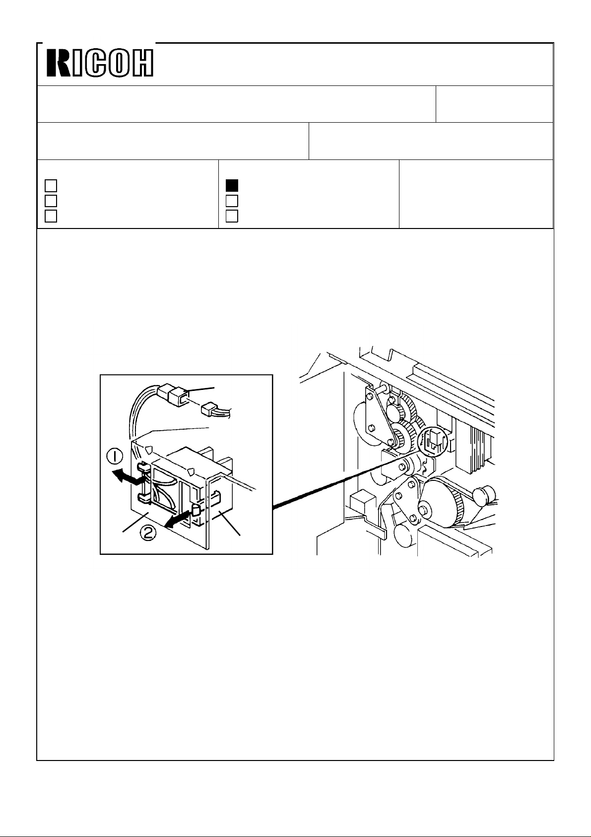
• Install the color switch [A] on the color switch bracket [B] as shown.
• Connect the color switch connector [C] to the dc harness (3P brown).
• Reassemble the copier.
[A]
Page 3

Technical Bulletin No. RTB-002
SUBJECT: Color Development Unit Installation Procedure DATE: 15 May, ’92
PAGE: 2 of 2
NOTE: This additional procedure is not required for the machines produced in January
and February as they have the color switches installed at the factory.
The color switch has been enclosed in the carton box of the color development
unit as an accessory from the first mass-production.
Page 4
Technical Bulletin No. RTB-003
SUBJECT: Dirty Pressure Roller with Toner and Paper Dust DATE: 15 May, ’92
PAGE: 1 of 1
PREPARED BY: M. Furusawa
CHECKED BY: T. Morita
CLASSIFICATION:
Action Required
Troubleshooting
Retrofit Information
[Symptom]
The pressure roller becomes dirty with toner and paper dust. The toner on the pressure
roller surface sometimes adheres on the reverse side of the copy paper. If the mass of
toner on the roller is large, a partially unfused image may appear.
[Cause]
Toner particles and paper dust on the pressure roller accumulate on the antistatic brush
which slightly touches the pressure roller. Masses of toner and paper dust on the brush
adheres the pressure roller surface by the vibration of the fusing unit when the main motor
is rotating.
[Action in the field]
Remove the antistatic brush for the pressure roller according to the following procedure:
Revision of service manual
Information only
Other
FROM: Copier Technical Support Section
MODEL: A7 Series
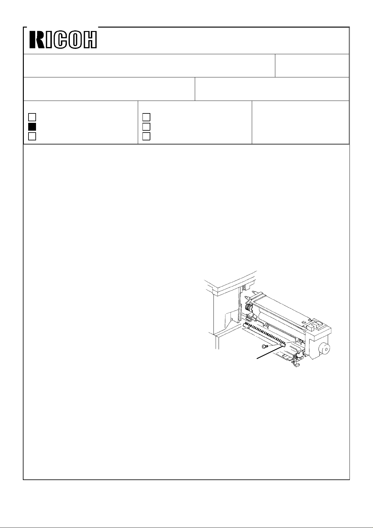
1. Open the front door and pull the fusing unit
all the way out.
2. Open the fusing exit unit.
3. Remove the antistatic brush [A] (2 screws).
4. Clean the pressure roller surface with
silicone oil.
NOTE: The antistatic brush is installed to
prevent very thin translucent paper
from wrapping around the pressure
roller due to static electricity.
As such very thin paper is not used normally in overseas markets, removing the
antistatic brush will not cause any problem for using normal bond paper.
[Countermeasure at the factory]
The antistatic brush for the pressure roller has been removed at the factory since April
production.
[A]
Page 5
Technical Bulletin No. RTB-004
SUBJECT: Service Manual Correction DATE: 15 May, ’92
PAGE: 1 of 2
PREPARED BY: M. Furusawa
FROM: Copier Technical Support Section
CHECKED BY: T. Morita
CLASSIFICATION:
Action Required
Troubleshooting
Retrofit Information
Revision of service manual
Information only
Other
MODEL: A7 Series
Please correct your service manual as follows:
[DETAILED DESCRIPTIONS]
1.4.2 VL Pattern Detection (page 2-11)
(3rd paragraph)
The drum surface is developed with non image area bias [→VB0-20V] for both the bare
drum and VL pattern.
3.3.3 VR Correction (page 2-22)
(Graph)
Grid Bias Correction Voltage
-160V
Grid Bias Correction Voltage
-160V
-120V
-80V
-40V
0
27 40 57
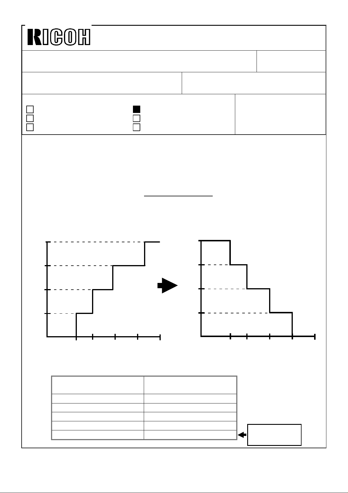
3.3.5 VG Correction (page 2-23)
(Table)
SP100: Drum Rotation
Time (H)
0 ~ 1
2 ~ 36 -20V
37 ~ 62 -40V
63 ~ 87 -60V
88 ~ -80V
-120V
-80V
-40V
83
100 (%)
0
Grid Bias Correction Voltage
±0V
40 57 83
27
This row should
be added.
100 (%)
Page 6
Technical Bulletin No. RTB-004
SUBJECT: Service Manual Correction DATE: 15 May, ’92
PAGE: 2 of 2
[SERVICE TABLES]
5.1 PM Table
EM 80K 160K 240K NOTE
PAPER FEED (for each paper feed station)
Paper Tray/LCT Bottom Plate
Pad
By-pass Feed Bottom Plate
Pad
[PAPER TRAY UNIT]
6.3 Tray Unit Drive and Paper Feed Clutch Replacement (page 21)
(Call outs of the illustration)
C R R R
C R R R
This column should be added.
Water
Water
[A]
[B]
[C]
[D]
[A]
[E]
[G]
[F]
Page 7

Technical Bulletin No. RTB-005
"BREAK"
[D]
SUBJECT: Development Mixing Auger Shaft Break DATE: 30 Sep. ’92
PAGE: 1 of 3
PREPARED BY: M. Furusawa
CHECKED BY: T. Ito
CLASSIFICATION:
Action Required
Troubleshooting
Retrofit Information
[PHENOMENON]
A grinding noise comes from the black development unit and uneven toner density
appears on copies from side to side. If the machine continues to run under these
conditions, the noise becomes bigger and copies become very light.
This problem might occur a few thousand to twenty thousand copies after the installation.
[CAUSE]
The mixing auger shaft [A] of the black development
unit’s cross mixing system breaks at the welding point
[B].
The mixing auger doesn’t rotate and the mixing auger
gear [C] starts making noise.
When the gear loses the mesh with the paddle roller
gears, the paddle rollers [D] stop rotating, and no
longer supply toner to the development roller sleeve.
This problem might happen on some machines
because of a poor welding by solder.
Revision of service manual
Information only
Other
FROM: Copier Technical Support Section
MODEL:
A7 Series (33 CPM)
[C]
[B]
[A]
[SOLUTION]
•• The welding method of the mixing auger has
been changed from solder to TIG to increase the
welding’s strength (about 2.5 times stronger). The
part number has been changed from AD037002
to AD037034.
•• The material of the bushing for the mixing auger
has also been changed to a softer one (from P/N AA080132 to P/N
52053103). The new material has a higher margin against developer
penetrating between the shaft and the bushing, which may increase
the load.
NOTE: As the illustration and the part number of the mixing auger are not listed in the
parts catalog, the new part number of the mixing auger has been announced by
M/B No.7 without mentioning the old part number. The part number change of the
bushing was also announced by M/B No.7.
The new mixing auger and bushing have been applied to the production machines
since the beginning of July, 1992.
Page 8

Technical Bulletin No. RTB-005
SUBJECT: Development Mixing Auger Shaft Break DATE: 30 Sep. ’92
PAGE: 2 of 3
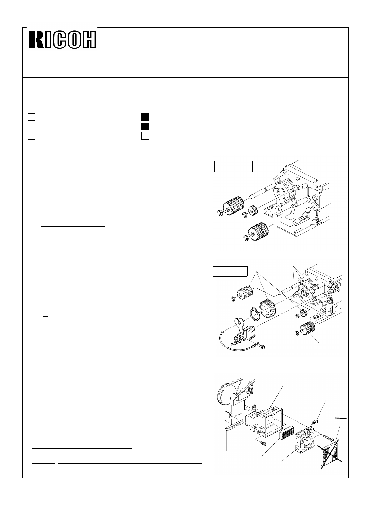
When this problem happens, replace the parts listed below according to the following
replacement procedure:
Required parts:
No. Part Number Description Q’ty Note
1. AD037034 Mixing Auger 1
2. 52053103 Bushing - 6mm 1
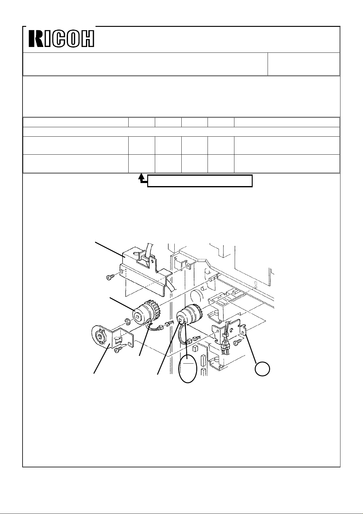
3. AB 013694
Replacement Procedure:
1. Pull out the development unit from the copier.
Gear - 19Z
Replace if the gear
1
teeth are worn out.
2. Remove the developer from the development unit.
NOTE: Keep the developer clean to re-use it after this parts replacement.
3. Remove the gear [A] from the mixing
auger shaft (1 E-ring).
4. Remove the paddle roller gear [B] (1
E-ring).
5. Pull out the mixing auger [C] from
the rear side of the development unit
together with the bushing [D] (1
E-ring at the front).
6. Install the new mixing auger and
bushing.
NOTE: Be careful not to damage the inside seal when inserting the bushing on the shaft.
7. Install the paddle roller gear and the mixing auger gear (if the teeth are worn out, use a
new one).
8. Clean the development unit gears and lubricate them with Silicone Grease G-40M.
Illustration for upper dev. unit
[B]
[A]
[D]
[C]
[A]
[B]
9. Pour the removed developer into the development unit.
10. Install the development unit in the copier and access the SP mode by turning on the
main switch while pressing both "1" and "3".
Page 9

Technical Bulletin No. RTB-005
SUBJECT: Development Mixing Auger Shaft Break DATE: 30 Sep. ’92
PAGE: 3 of 3
11. Place a few sheets of white paper on the exposure glass and run the machine in free
run mode (SP2) until Vsp becomes about one tenth of Vsg. (Monitor by SP55.)
NOTE: If the toner density is very low, you may use SP9-13 (Note 1) to supply toner
manually.
If the toner density is too high, reset the free run mode by SP3 and make sky shot
copies until toner density reaches a proper level.
12. Exit the SP mode by turning the main switch off and on, then check copy quality.
Page 10

Technica l Bulletin No . RTB-00 6
SUBJECT: Drum Heater and Upper Paper Tray Heater DATE: Dec .15, ’92
PAGE: 1 o f 1
PREPARED BY: M . Fu ru saw a
CHECKED BY: T. Ito
CLASSIFICATION:
Action Required
Troubleshooting
Retrofit Information
Please be informed that from the first mass production the drum heater has been
disconnected or eliminated. The upper tray heater has been installed instead.
The reason is that a problem was observed in the Japanese domestic market before
starting a mass-production of the export version, and the above action is a
countermeasure to it.
[ Problem]
Partially blan k c op ies o r ligh t imag es ap pear at inter vals equ al to t he dr um’ s per iph eral
length. They appear for about the first 10 or so cop ies in the morning. The problem
occurs from the day after machine installation and c ontinues for about a week. After the
problem disappears, it will not reoccur even after changing the drum, developer, etc.
This problem is not so visible when copying text originals, but it is visible when copying
blue lined graph paper or orange paper. The actual claim ratio in Japan was about 1%.
Revision of service manual
Information only
Other
FROM: Copier Technical Support Section
MODEL:
A7 Series
(A069/A073/ A074)
[ Cause]
Some c hemic al sub st ance an d o zon e o r NOx reac t to mak e a ch emic al layer o n the T& S
corona casing. When the main switch is turned off, the drum heater turns on. During the
night this chemical layer evaporates because of the heat from the drum heater. Some
ot her ch emic al sub s tanc e also evap o rates fro m the heater tu be. The ad her ed ch emic al
layer on the drum surface tends to get humid. This lowers the resistance of the
ph ot oc o nd uc tive lay er, c aus ing par tially b lank o r lig ht im ag es.
[ Countermeasure]
Since it is d iffic ult to c o mp let ely elim inat e t he c hem ic al su bs tan c es fr om t he m ach ine, it
has been decided not to install the drum heater.
To avoid cond ensation on the drum surface, the upper tray heater is installed instead of
the d r um h eater . The u pp er tr ay heat er w as was or ig inally availab le as a s ervice p ar t t o
pr event c reasin g aft er fusin g.
Production machines from the first mass production have had their drum heaters
disconnected, and have had upper tray heaters installed.
Production machines from mid-March on do not have drum heaters, and have upper tray
heaters.
Page 11
Technica l Bulletin No . RTB-00 7
SUBJECT: SC54 and SC55 (220/ 230/ 240V machines only) DATE: Dec . 15, ’ 92
PAGE: 1 o f 2
PREPARED BY: M . Fu ru saw a
CHECKED BY: T. Ito
CLASSIFICATION:
Action Required
Troubleshooting
Retrofit Information
Phenomenon:
SC55 (Fusing overheat) occurs during the operation. This condition may be reset by
entering to the SP mo de. However, the interval to the next SC55 becomes shorter and
shorter and finally it can’t be reset. SC54 (Fusing warm-up error) may occur instead of
SC55 under the same condition. This is a very rare problem but it may occur during
installation or soo n after installation.
This p ro blem happ ens on ly on th e 220/230/ 240V mach ines b ecau se o f its inp ut voltag e.
The occurrence ratio reported till now is 0.2%. This ratio represents the affected portion
of the total machines produced (we do not know the total number of machines in the
field) .
Possible ca use:
The surge current to the fusing triac (TRC402) of the dc power supply board when the
main switch is turned on might cause the triac to deteriorate little by little. This depends
on co nd itio ns suc h as in pu t vo ltag e fluc tuat ion and co mb inat ion of var iou s elect ric al
component’s torelance. When the deterioration of the triac reaches a certain level, the
triac will start conducting half waves. The CPU cannot control the fusing temperature
und er t his c on dit ion , c ausin g SC55 o r SC54.
The sequence of the electrical component (main switch, power relay, and fusing triac)
ON timing when the main switch is turned on may result in a large surge current to the
fusing triac.
Revision of service manual
Information only
Other
FROM: Copier Technical Support Section
MODEL:
A7 Series
(A069/A073/ A074)
Action in the fie ld:
The fo llow ing actio n is req uir ed in the field :
Chang e t he set ting o f SP29 (Fusing temp er atur e c on tro l m od e) fro m "0" (ON/ OFF
contro l) to "1" (Phase control) at the next visit to customers or at machine installation.
NOTE: Please cor rec t t he exp lanatio n o f SP29 in your ser vice m anual ( Pages 2-103 and
4-14 ). Dat a "0" is n ot fo r "Zer o -c ro s s c o n tr o l" b ut fo r "O N/ OFF c o nt r o l".
[E xplanation]
Phase control mode will not give any chance of a large surge current to the fusing triac
as the sequence of the electrical component ON timing is different from that in ON/OFF
control mode. Therefore, once the fusing control is changed to Phase control mode, the
fusin g t riac will never det erio rat e.
This c op ier c o ntr o ls th e fusin g temp er atur e in ON/ OFF co nt ro l mo d e as a s tand ard .
However, it can be changed to Phase control mode in case electric lights go darker
briefly when the fusing lamp kicks in under poor electric power supply conditions.
Page 12

Technica l Bulletin No . RTB-00 7
SUBJECT: SC54 and SC55 (220/ 230/ 240V machines only) DATE: Dec . 15, ’ 92
PAGE: 2 o f 2
On the other hand, it won’t give any trouble in Phase control mode under normal
conditions, but some electrical equipment might have a little electrical noise if it is
connected to the same wall outlet with the copier.
Considering the difference between the two control modes, Ricoh has decided to use
the Phase control mod e as a countermeasure for the machines in fields.
Permanent countermeasure:
The software of the main ROM will be modified to correct the sequence of the electrical
co mp o n ent ON tim ing . This will allo w th e alter nat ive selec tio n o f either ON /OFF o r
Phase control mode in the field as intended in the machine design.
The part numbers of the main ROM and the main control board will be changed
through this mod ification.
The new part numbers and the cut-in serial numbers will be informed later by a
Modification Bulletin.
Page 13
Technica l Bulletin No . RTB-00 8
SUBJECT: Ne w Sorte r Stapler "M ATT20" DATE: Feb . 15, ’ 9 3
PAGE: 1 o f 1
PREPARED BY: M . Fu ru saw a
CHECKED BY: T. Ito
CLASSIFICATION:
Action Required
Troubleshooting
Retrofit Information
As it was informed by Modification Bulletin No. 32 issued on December 31,1992, a new
sor ter st apler "MATT20" (A374), or igin ally d esig ned fo r t he th e N440 s eries an d SP40, has
been adap ted to A7 ser ies co p iers with the main c o ntr ol b oard A0705145.
A7 series copiers now can have the following 5 kinds of sorters:
1. Mic ro Sorter (A327) : 10 movin g b ins
2. Mini Sor ter ( A423) : 20 m oving bin s
3. Mid i Sorter (A411) : 20 movin g b ins
4. Sort er Stap ler ( A366) : 20 fixed bin s ( Floo r ty pe)
New 5. Sorter Stapler "MATT20" (A374) : 20 moving bins (Hanging type)
[ Insta llation]
The following items are required to install the MATT 20 on A7 series copiers:
1. Sort er Ad ap ter (A328)
2. Int erface PCB (A344)
Revision of service manual
Information only
Other
FROM: Copier Technical Support Section
MODEL:
A7 Se r ie s
(A069/A073/A074)
NOTE: The MATT20 can be installed on the copiers with the main contro l board
A0705145 (Main ROM = A0705114) witho ut any ch ang e. Refer to M /B N o. 32 fo r
the cut-in serial numbers.
The copiers with the following main control boards need the modification:
1. A0705141: Replace t he main ROM fro m A0695114 to A0705164
2. A0705191: Replace t he main ROM fro m A0695114 to A0705164
* A0695191 cann ot b e used for MATT20 oper ation .
* A0705114 h as alread y been ch ang ed to A0705164 to p revent SC54/55 p r ob lem.
Refer to t he RTB-007. Mo d ificat ion b ulletin fo r th is P/N ch ang e w ill follo w s oo n .
There is n o c h ang e to th e A7 series co p iers for MATT20 co mp atib ility ot her than
the software. This software change does not affect the installation proc edure of the
or igin al so rt er s tap ler (A366) .
The main ROM size has been c hanged fro m 1 M -b yte to 2 M -b yte
enable the operation for both the original sorter stapler and the MATT20.
CAUTION: The MATT20 can be installed on almost all the A7 series copiers by
applying the above modification. However, you should not insta ll the M ATT20 on
the copiers produced before July, 1992. Becau se electric al safety st andar ds su ch
as UL, CSA, and TÜV, certify installing the MATT20 only on A7 series copiers
pr od uc ed fr om July 1992 on ward s .
in order to
♦ The installation procedure of the MATT20 to N440 series copiers (A085/ A087/A088) c an
be applied to A7 series copiers without any change.
Page 14
Technica l Bulletin No . RTB-00 9
[F]
[G]
[C]
[D]
[E]
SUBJECT: Service M anua l Corre ction DATE: Feb .15 , ’ 93
PAGE: 1 o f 1
PREPARED BY: M . Fu ru saw a
CHECKED BY: T. Ito
CLASSIFICATION:
Action Required
Troubleshooting
Retrofit Information
Please correct your service manual as follows:
SECTI ON 4. SERVIC E TABLES
5. PREVENTIVE M AINTENANCE SCHEDULE
5.1 PM TABLE
Not e3: Fusing Sectio n ( Page 4-43)
[I nco rrect]
(2)Fusing Dr ive Gears
Replace th e fusing d rive g ears [F] ever y 160K.
Then, lubricate them and their shafts [G] with
Grease G501.
[C orre ct]
Revision of service manual
Information only
Other
FROM: Copier Technical Support Section
MODEL:
A7 series
(A069/A073/A074)
[ Incorrect]
[G]
[H]
[F]
[ Correct]
(2)Fusing Drive Gears
Replace th e fusing d rive g ears [F] ever y 160K.
Then, lu br icat e the g ears [F,G] and their shafts
[ H] w ith Grease G501.
SECTION 5. REPLACEMENT AND ADJUSTMENT
10. OTHERS
10.1 OZONE FILTER REPLACEM ENT
[I nco rrect]
10.1.2 Vac uum Fan Filters (Page 5-110)
[C orre ct]
10.1.2 Exhaust Fan Filter
Delete step 3 as the paper type ozone filter [A] has
been elimin ated fr om t he p ro d uc tio n mac hin es
because it was proved that only a ceramic type
ozone filter [ E] can maintain the required ozone level.
Refer to Modification Bulletin No.35.
3. Remove t he o zon e filter [A] .
NOTE: The PM interval of this paper ozone filter is
80K co pies.
[G]
[B]
[A]
Page 15
Technica l Bulletin No . RTB-01 0
[B]
SUBJECT: Sorter Stapler ( A366) Gripper Ope ration DATE: Feb . 15, ’ 9 3
PAGE: 1 o f 2
PREPARED BY: M . Fu ru saw a
FROM: Copier Technical Support Section
CHECKED BY: T. Ito
CLASSIFICATION:
Action Required
Troubleshooting
Retrofit Information
Revision of service manual
Information only
Other
MODEL:
A7 Series
(A069/A073/A074)
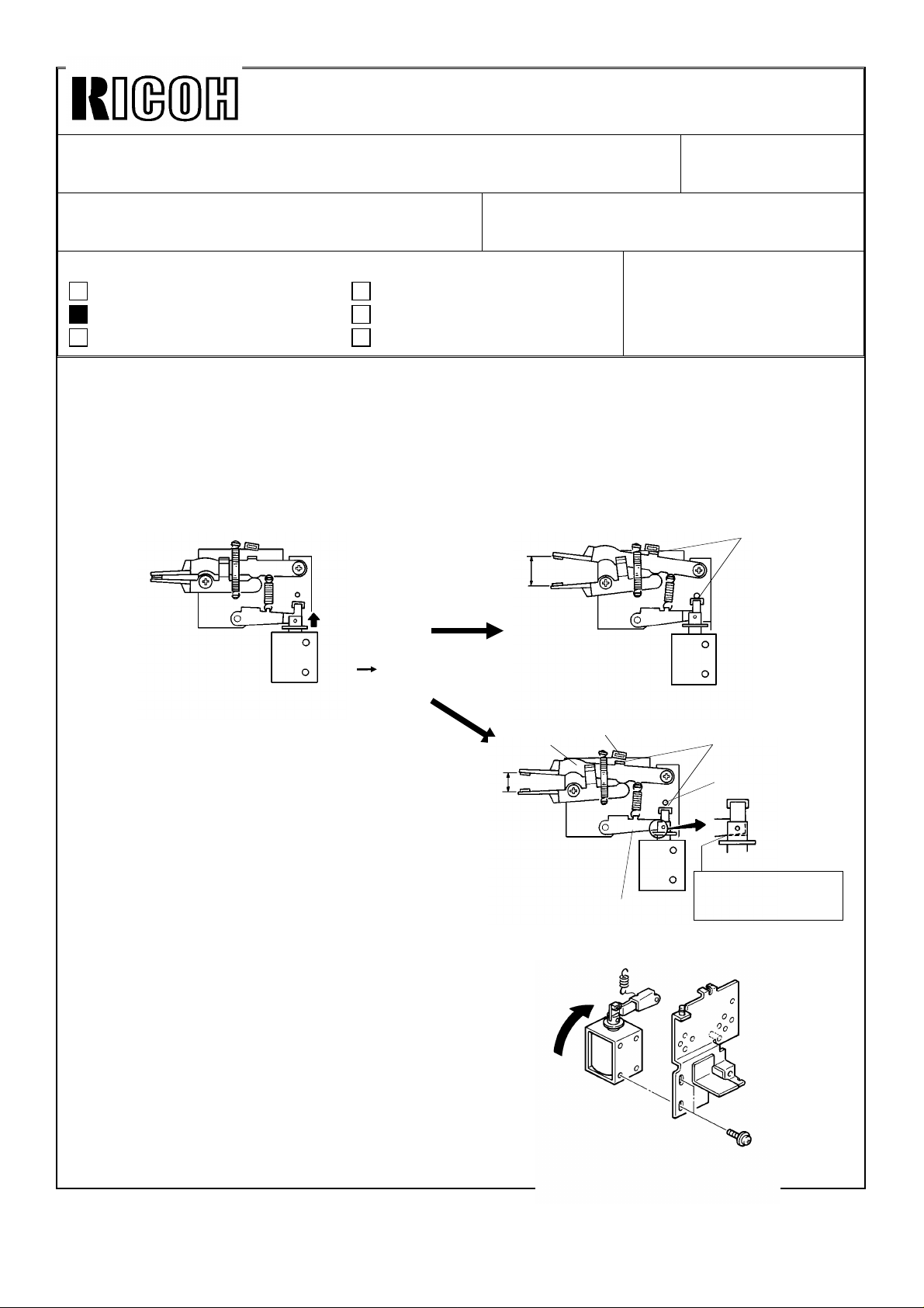
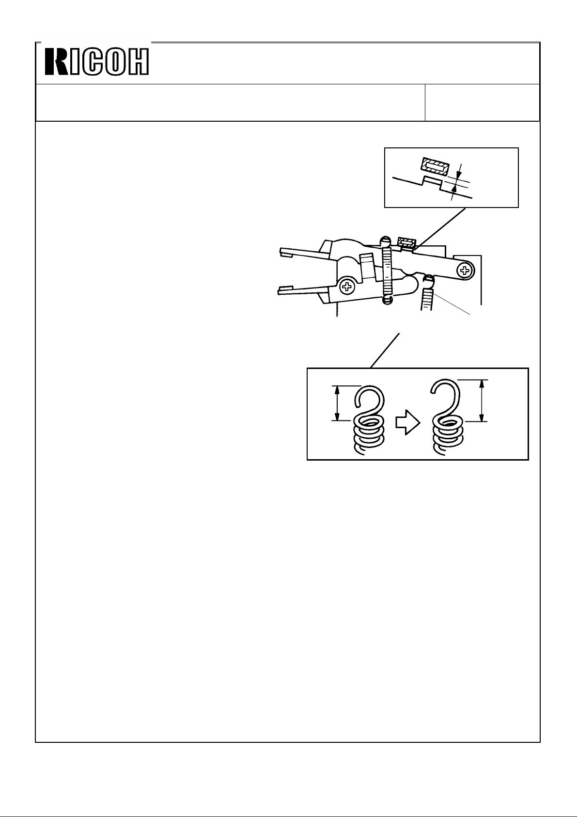
[PHENOMENON]
During stapling operation, the gripper pushes the bottom cop y out of position.
[CAUSE]
The grippers are not opening wide enough.
24 - 25 mm
SOL.
ON OFF
[OK]
No Gap
When t he g rip s o leno id tu rn s o ff, th e
grippers should open wide enough.
If th e so leno id p lu ng er is c aug h t b y t he
solenoid arm [ A] , the arm and the upper
gripper [B] cannot reach the stoppers
[C,D]. Refer to the figure [NG].
[ACTION]
1. Loosen the screws securing the grip
so len o id .
Then tighten the screws while turning the
grip solenoid, as shown by the arrow at the
right.
NOTE: Make sure that the solenoid stroke is
maintained for 2.5 ± 0.5 mm.
20 mm
[NG]
[D]
[A]
Gap
[C]
Plunger is caught at
this point and stops.
Page 16
Technica l Bulletin No . RTB-01 0
SUBJECT: Sorter Stapler ( A366) Gripper Ope ration DATE: Feb . 15, ’93
PAGE: 2 o f 2
2. If there still be a gap "A" after performing step 1,
lengthen the solenoid arm spring [ E] as shown.
NOTE: Be careful not to lengthen the spring too much,
or the spring will not hook the gripper properly.
Leng then by "A" as sho wn.
With the above two actions the width
of the gripper opening can be
adjusted by about 5 mm.
x
A= Gap
[E]
x+ A
Page 17

Technica l Bulletin No . RTB-01 1
SUBJECT: Tray Heater Location (Duplex Machine: A074 Only) DATE: Feb . 15, ’ 9 3
PAGE: 1 o f 1
PREPARED BY: M . Fu ru saw a
CHECKED BY: T. Ito
CLASSIFICATION:
Action Required
Troubleshooting
Retrofit Information
The following problem was reported from Japanese domestic market.
[PROBLEM]
The duplex tray cannot be pulled out because the tray bottom part has been deformed
due to heat. Several cases were reported with the machines which were not used over
one week due to holidays.
[CAUSE]
The g ap b etw een t he tr ay h eater b rac k et an d t he d u plex tr ay b o tt om par t is 7.6 m m, w hile
that bet ween t he t ray h eater b rac ket and t he p aper tr ay b o tto m p art is 20.2 m m.
Since this gap of duplex machines is not wide enough, the duplex bottom part may be
defo rm ed d ue t o h eat fr om th e tr ay h eater w hen the m ac hines are n ot us ed w ith the
power cord plugged in for a long period (long holidays). When the deformation of the
duplex tray bottom part becomes much, the duplex tray may not be pulled out.
Revision of service manual
Information only
Other
FROM: Copier Technical Support Section
MODEL:
A7 Series
(A069/A073/A074)
[ACTION IN THE FIELD]
Refer to 2. 5 TRAY H EATER INSTALLATION (Page 3-21) in t he ser vice m anu al.
The fo llowin g ac tio n is req uired fo r th e duplex machines (A074):
•• For the area with not so high humidity, disconnect the upper tray
heater at t he n ext PM c all.
•• For the area with high humidity, change the location of the tray heater
from the upper tray to the lower tray at the next PM c all.
[PERM ANENT COUN TERM EASURE]
Prod uc tio n mac hin es will have a new heater on the 6th mirro r b rac k et and the u pp er tr ay
heat er will b e elimin ated . The d et ail and the c ut- in ser ial num b ers w ill be in for med b y a
Modification Bulletin later.
Page 18

Technica l Bulletin No . RTB-01 2
[Figure 3]
Sup er
Glue
NG
OK
SUBJECT: Toner Cartridge not Set Correctly DATE: Feb . 15, ’ 9 3
PAGE: 1 o f 1
PREPARED BY: M . Fu ru saw a
CHECKED BY: T. Ito
CLASSIFICATION:
Action Required
Troubleshooting
Retrofit Information
[PROBLEM]
When a toner cartridge is set in the wrong position as
shown in figure 2, the "Add Toner" indicator comes on
again.
[CAUSE]
When a toner cartridge is forced to turn or when it is turned
by being pressed to the right side, the upper and lower
casin gs will b e warp ed and m ake a gap at the fr on t left
side. Then the cartridge stops at the overturned position as
shown. Under this condition, the toner supply opening of
the toner cartridge does not match the toner supply roller
opening, causing toner not to be supplied.
Revision of service manual
Information only
Other
FROM: Copier Technical Support Section
MODEL:
A7 Series
(A069/A073/A074)
[Figure 1]
[ACTION IN THE FIELD]
1. Remove the toner cartridge from the toner supply unit.
2. Clean t he up per and lower casin gs at the fr on t left sid e
with a dry cloth, then adhere the upper and lower
casings with super glue as shown in figure 3.
3. Since it may take twenty to thirty minutes
for the super glue to dry, stick a strip of
tape on the toner supply unit casing as
shown.
4. Reinstall the toner cartridge.
[PERM ANENT COUN TERM EASURE]
The lower casing will be modified to ensure
a proper stop position of the toner
cartridge, and a strip of tape (matching this
field action) will be stuck at the factory.
Details a nd cu t-in seria l num ber s w ill be
sent later by a Modification Bulletin.
[Figure 2]
Tape
Page 19

Technica l Bulletin No . RTB-01 3
[A]
SUBJECT: Rubber Feet on Copier Base Plate DATE:Mar. 15, ’ 93
PAGE: 1 o f 1
PREPARED BY: M . Fu ru saw a
CHECKED BY: T. Ito
CLASSIFICATION:
Action Required
Troubleshooting
Retrofit Information
Please be info rm ed th at th e mat erial for r ub ber feet [A] o n t he c op ier bas e plat e has been
changed from hard rubber to molding since June, 1992.
The reas on is as fo llo ws:
When the copier is installed on the paper tray unit, the
rub ber feet are c om pr essed by the c op ier’ s weig ht an d
they may be shortened.
When this occurs the gear mesh between the tray unit
drive and driven gears [B,C] b ecomes tight, causing
noise.
To p revent this, t he mat erial of t he feet has b een
changed to a hard one. The part number has not been
changed.
Revision of service manual
Information only
Other
FROM: Copier Technical Support Section
MODEL:
A7 S e r ie s
(A069/A073/A074)
[A]
As the height of the A7 copier is above that of other
cop iers, the copier will be installed on the paper tray
unit or its unique table normally, in order to operate the
co pier easily.
However, in case that the copier is installed on a
normal commercial table, please note that the c opier
may slip on the table rather easily with the new feet.
If the c o p ier slip s eas ily o n t he t able, it is ad vised t o
stick rubber plates on the feet by glue or two sided
tape for safety. You can use a commercial rubber plate
and cut it for the feet .
[B]
[C]
Page 20

Technica l Bulletin No . RTB-01 4
[B]
[E]
SUBJECT: Sorter Stapler "MATT20" (A374)
Pape r J ams in T urn Gate Se ction
PREPARED BY: M . Fu ru saw a
CHECKED BY: T. Ito
CLASSIFICATION:
Action Required
Troubleshooting
Retrofit Information
[PHENOMENON]
Paper jams occur in the turn gate section [A] intermittently in
sort, stack, or staple mode.
[PO SSIBLE CAUSE]
The so rt er ad ap ter lo wer exit ro ller [B] has a stiffn ess in cr easing
ro ller [ C ] at t he mid dle. This rub b er ro ller has a flange o n eac h
end. The flanges produce slight waves on copy paper
perpendicular to the paper transport direction to increase
paper stiffness.
The rear side wave position may not be proper for one of
the ribs on the sorter stapler vertical paper guide [ D]
especially when paper has excessive face curl. The rib may
make a mark on the paper lead edge or may cause paper
jams.
Revision of service manual
Information only
Other
FROM: Copier Technical Support Section
DATE: Mar. 15, ’93
PAGE: 1 o f 1
MODEL:
A7 Series
(A069/A073/A074)
[A]
[D]
[ACTION IN THE FIELD]
1. Cut off the rear flange [E] with cutting pliers and smoo th
the r olle r’ s ed ge with a knife. This will elim inat e
the rear side wave on paper.
(As the flanges have wedge grooves originally
and the roller is turning in forwarding direction,
the r olle r sur fac e do es n ot have to b e co mp let ely
smooth after you cut off the flange.)
2. If step 1 does not cure the problem, cut off the
fro nt flang e [F] as well.
(Paper transport reliability without flanges on the
roller was tested for thin paper under high
hum id ity c o nd itio n, resu lting in no p r ob lem .)
[PERM ANENT COUN TERM EASURE]
The width of the rib on the sorter stapler vertical paper guide will be increased to improve
the paper transport ability. The part number of the vertical paper guide will remain as it is.
This mo d ificatio n will b e app lied t o t he p ro du ctio n m ach ines fr om April, 1993.
[C]
[F]
Page 21

Technica l Bulletin No . RTB-01 5
SUBJECT: ARDF Origin al misfe ed. DATE:
Mar. 15, 1993
PAGE: 1 o f 2
PREPARED BY: N . Tak ai/ M. Fur us awa
CHECKED BY:
CLASSIFICATION:
Action Required
Troubleshooting
Retrofit Information
Revision of service manual
Information only
Other
FROM: Copier Technical Support Section
MODEL:
A7 Series
(A069/A073/ A074)
Symptom:
Original misfeed occ urs intermittently.
Possible Ca use:
1. The DF registration sensor is activated by paper dust on the sensor pad, affecting its
color.
2. When t he o rig inal feed ro ller star ts r ot ating , t he DF up pe r g uid e plat e is war ped slig ht ly
downward. The clearance between the DF registration sensor and the sensor pad is
reduced. When this happens, the DF registration sensor (reflective type) can receive the
reflective light from the sensor pad, even though its color is black.
Action Required:
(For cause 1)
1. Op en th e feed -in un it [A] .
2. Clean t he DF regist ratio n s enso r
surface [B] and the sensor pad [C].
NOTE: To remove the paper dust from
the sensor pad, it is better to
use scotch tape.
[B]
[C]
[A]
Page 22

Technica l Bulletin No . RTB-01 5
[D]
SUBJECT: ARDF Origin al misfe ed. DATE:
Mar. 15, 1993
PAGE: 2 o f 2
(For cause 2)
1. Remove the two screws of the pull out
hinge [D].
2. Ins ert 2 pc s eac h of 0. 8 mm sp ac er
(P/No . 07010040) and fix th e sc rew s.
[E].
•
This c an g ive the reg ist ratio n s enso r
enough clearance for the sensor pad.
[E]
Perma nent Counterme asure :
The shap e of t he pu ll ou t br ack et (P/N o. A4651057) will be mo d ified so that the sen sor
pad is positioned 1.5 mm further from the DF registration sensor.
Soon after the modification is applied to the produc tion, an M/B will be issued.
Page 23

Technical Bulletin No. RTB-016
SUBJECT: SC54 and SC55 (220/230/240V machines only)
Additional information
PREPARED BY: M. Furusawa
CHECKED BY: T. Ito
CLASSIFICATION:
Action Required
Troubleshooting
Retrofit Information
Refer to the RTB No.007 for the phenomenon, possible cause, and action in the field
concerning the above subject.
The following is additional information for the permanent countermeasure:
As it is mentioned in the RTB No.007, the software of the main ROM has been modified to
correct the sequence of the electrical component (main switch, power relay, and fusing
triac) ON timing.
The part numbers of the main ROM and the main control board have been changed as
follows (Refer to the M/B No.42 for the cut-in serial numbers.):
Main ROM: (Old) A0705114 (New) A0705164
Main Control Board:(Old) A0705145 (New) A0705175
Revision of service manual
Information only
Other
FROM: Copier Technical Support Section
MODEL:
A7 Series
(A069/A073/A074)
DATE: May 15, ’93
PAGE: 1 of 1
The software of the I/O ROM (IC132) soldered on the main control board has also been
modified in addition to the above modification (Refer to the M/B No.44 for the cut-in serial
numbers.):
I/O ROM: (Old) A0705127 (New) A0705127
Main Control Board:(Old) A0705175 (New) A0705180
[Explanation]
With the modified main ROM, the copier can operate in ON/OFF control mode without
deteriorating the fusing triac (TRC402) under normal usage conditions.
However, the fusing triac might deteriorate gradually when the following three steps
occur together although the possibilities of this occurring are very low:
1. The main switch is ON.
2. The front door is open.
3. Then the front door is closed when the fusing temperature becomes low (nearly
room temperature).
To eliminate this possibility, the software of the I/O ROM has been modified as the
second countermeasure.
The countermeasures have been applied in two steps as mentioned above because the
modification of the masked type I/O ROM took time.
In case of the machines with only the first countermeasure, the modified main ROM, the
above possibility occurring can be eliminated by setting the data of SP29 (Fusing
temperature control mode) at "1" (phase control) without changing the I/O ROM.
Page 24

Technical Bulletin No. RTB-017
SUBJECT: Sorter Stapler (Matt20)
Bin Lift Wire Installation Procedure
PREPARED BY: M. Furusawa
CHECKED BY: T. Ito
CLASSIFICATION:
Action Required
Troubleshooting
Retrofit Information
The bin lift wire may loosen on the wire pulley during
transportation. When the wire pulley is driven from the
home position under this condition, the wire may be
wound up wrongly as shown in the figure 1. This will
change the bin stop positions, resulting in paper jams.
To eliminate this possibility, the bin lift wire has been
lengthened as shown in the figure 2. This will give another
half turn of the lift wire on the pulley to prevent the wire
from being wound up wrongly.
Revision of service manual
Information only
Other
FROM: Copier Technical Support Section
DATE: July 31, ’93
PAGE: 1 of 2
MODEL:
A7 Series
(A069/A073/A074)
OK
[Figure 1]
NG
Refer to the Modification Bulletin No. 7
(Model: Sorter stapler for A7/N440) for
the cut-in serial numbers.
With this modification, the wire
installation procedure should be altered
as follows when replacing the wire with
the new type.
Service Manual:
SORTER STAPLER (A374)
15. REPLACEMENT AND ADJUSTMENT
15.4 BIN LIFT WIRE REPLACEMENT
15.4.2 Wire Installation (Page 46)
Step 3
For the old type:
Wind the wire once as shown and ---Refer to the figures 3 and 5 in the next page.
For the new type:
Wind the wire one and a half turns as shown and -----Refer to the figures 4 and 6 in the next page.
[Figure 2]
NOTE: When replacing either of front and rear wires with the new type, the wire
installation procedure should be a combination of those for the old and new types.
It won’t give any problem.
Page 25

Technical Bulletin No. RTB-017
SUBJECT: Sorter Stapler (Matt20)
Bin Lift Wire Installation Procedure
FRONT SIDE:
= Old type =
[Figure 3]
DATE: July 31, ’93
PAGE: 2 of 2
= New type =
[Figure 4]
REAR SIDE:
= Old type =
[Figure 5]
= New type =
[Figure 6]
Page 26

Technical Bulletin No. RTB-018
SUBJECT: Sorter Stapler (Matt20)
Paper Exit Jam
PREPARED BY: J. Mochizuki
CHECKED BY:
CLASSIFICATION:
Action Required
Troubleshooting
Retrofit Information
FROM: 2nd Technical Support Section
Revision of service manual
Information only
Other
MODEL:
A7 Series
(A069/A073/A074)
DATE: Feb. 15,’94
PAGE: 1 of 2
Symptom:
In Sort/Stack mode, when copy paper is fed out to a bin, the roller drive motor speed
becomes higher. The motor occasionally hesitates at that moment, paper exit jam occurs.
Possible Cause:
The load of the roller drive motor is too large. The friction between the shafts and bearings
exceeds the roller drive motor torque.
Action Required:
1. Lubricate the the following parts using launa oil.
1) Between the bushings [A] and shafts
2) Between the exit rollers [B] and the shafts [C]
[B]
[C]
[A]
[A]
Page 27

Technical Bulletin No. RTB-018
SUBJECT: Sorter Stapler (Matt20)
Paper Exit Jam
2. Reduce the timing belt tension.
1) Remove the proof tray.
2) Remove the rear cover.
3) Loosen the screws fixing the roller drive motor [A] bracket.
4) Slightly reduce the timing belt [B] tension, and retighten the screw.
Note: After reducing the belt tension, make A3 size copies in normal mode to make sure
no belt jumping.
[A]
[B]
DATE: Feb. 15,’94
PAGE: 2 of 2
Page 28

Technical Bulletin No. RTB-019
SUBJECT: SC54 and SC55 (220V/230V/240V machines only) DATE: June 15, ’94
PAGE: 1 of 1
PREPARED BY: J. Mochizuki
CHECKED BY:
CLASSIFICATION:
Action Required
Troubleshooting
Retrofit Information
Please refer to the RTB No. 007 for the nature of the ploblem and possible cause
concerning the above subject.
To increase the margin against the surge current, the triac TRC402 used on the DC power
supply board has been changed to one which permits higher surge current.
This modification has been applied since the December ’94 production.
Due to field requests, the new triac has been registered as a service part. The part
number is 14050239. The location of the triac TRC402 is as shown in the illustration below:
Revision of service manual
Information only
Other
FROM: 2nd Technical Support Section
MODEL:
A7 Series
(A069/A073/A074)
TRC402
DC Power Supply
Page 29

Technical Bulletin No. RTB-019
SUBJECT: MATT20 (A374) TROUBLESHOOTING GUIDE DATE: Oct. 31, ’94
PAGE: 1 of 12
PREPARED BY: F. Noguchi
CHECKED BY: S. Hamano
CLASSIFICATION:
Action Required
Troubleshooting
Retrofit Information
To aid the technician in troubleshooting matt20 misfeeds we are issuing this
troubleshooting guide. If the guide is used properly it will resolve the majority of
misfeeding problems the field is experiencing.
Revision of service manual
Information only
Other
FROM: Copier Technical Support Section
MODEL: A7
TABLE OF CONTENTS SYMPTOM TYPE
1. Roller Drive Motor Stalls and Paper Exit Jams.
2. Sorter Bin Jams or Copies out of order.
3. Incorrect Bin Position and Bin Entrance Jams.
4. Proof Tray Jams with Thick Paper.
5. Sorter Stapler Paper Jams in Turn Gate Section. (RTB - 014)
6. Turn Gate Area Misfeeds.
Page 30

Technical Bulletin No. RTB- 019
SUBJECT: MATT20 (A374) TROUBLESHOOTING GUIDE DATE: Oct. 31, ’94
PAGE: 2 of 12
1. ROLLER DRIVE MOTOR STALLS AND PAPER EXIT JAMS
[Symptom]
In Sort/Stack mode, when copy paper is fed out to a bin, the roller drive motor speed
should become higher. The motor occasionally hesitates at that moment and paper exit
jam occurs.
[Possible Cause]
The load of the roller drive motor is excessive when the roller shafts and bushing became
dirty, the friction between the roller shafts and bushings exceeds the roller drive motor
torque.
[Action Required]
Lubricate the drive parts using launa oil. (See page 2 ∼ 4)
NOTE : If the drive parts have not been initially cleaned with alcohol, clean them before
lubricating.
Page 31

Technical Bulletin No. RTB-019
SUBJECT: MATT20 (A374) TROUBLESHOOTING GUIDE DATE: Oct. 31, ’94
PAGE: 3 of 12
LUBRICATION
[B]
[A]
[C]
To reduce the load to the roller drive motor, lubricate as follows at every PM:
1. Open the sorter stapler then disconnect the link lever [A] (1 stepped screw).
2. Disconnect the sorter stapler interface harnesses and a grounding wire (1 screw).
3. Remove the sorter stapler from the mounting frame.
4. Remove the proof tray [B] (1 screw).
5. Remove the rear covers [C] (6 screws).
Page 32

Technical Bulletin No. RTB-019
SUBJECT: MATT20 (A374) TROUBLESHOOTING GUIDE DATE: Oct. 31, ’94
PAGE: 4 of 12
[A]
[A]
[D]
Exit Roller
[C]
[D]
[C]
Old
[B]
6. Lubricate the bushings [A] with launa oil.
NOTE: Lubricate the bushings from the both sides so that the oil is fully supplied between
the shaft and the bushing.
7. Gently push down the support bin [B] then lubricate the exit rollers [C] with launa oil.
NOTE: 1. Lubricate the inner side of the brackets [D] so that launa oil is fully supplied
between the shaft and the roller.
2. When the exit rollers [C] are replaced with new ones (P/N A3742541), no
lubrication at every PM will be required.
This is because the new exit roller contains oil in the bushing.
New
Page 33

Technical Bulletin No. RTB-019
[B]
SUBJECT: MATT20 (A374) TROUBLESHOOTING GUIDE DATE: Oct. 31, ’94
PAGE: 5 of 12
[A]
[A]
[D]
[C]
[E]
[B]
8. Lubricate the bushings [A] with launa oil.
NOTE: Lubricate the bushings from the both sides so that the oil is fully supplied between
the shaft and the bushing.
9. Lubricate the bushings [B] and gear pulley [C] with launa oil.
NOTE: Place a sheet of paper underneath the bushing so that the oil does not drop on
the guide plate.
Wipe off excess oil so that launa oil does not drop on the guide plate during
copying.
10. Lubricate the pulse generator disc [D] and idle pulley [E] with launa oil.
Page 34

Technical Bulletin No. RTB-019
SUBJECT: MATT20 (A374) TROUBLESHOOTING GUIDE DATE: Oct. 31 ’94
PAGE: 6 of 12
2. SORTER BIN JAMS OR COPIES OUT OF ORDER
[Symptom]
The copy’s trailing edge [A] remains on the guide mylar [B]. When the following paper [C]
comes to the bin, it hits the trailing edge of the proceeding paper, resulting in the paper
jam, or incorrect copy order when the following paper goes underneath the proceeding
paper.
[A]
[C]
[B]
[Cause]
The technician bent the lower bin exit roller holder (spring plate) ( P/N : A3742163) [D],
trying to correct the normal paper skew when the paper exits into the bins. This reduces
the paper transport ability causing bin jams.
[D]
Page 35

Technical Bulletin No. RTB-019
SUBJECT: TROUBLESHOOTING GUIDE DATE: Oct. 31 ’94
PAGE: 7 of 12
• Supplemental Technical Explanation about the way how paper is
stacked in the bin.
When the copy paper comes out of the sorter, it is angled. This is normal for proper
stacking of the copy paper.
[Mechanism of Paper Stacking]
1. As shown in the illustration, the front side of paper [A] comes out of the sorter first.
NOTE: In order to angle the paper, the diameter of the front and rear transport rollers [B]
are slightly different (front roller: 20.0mm [a], rear roller : 19.7mm [b]).
2. After the entire sheet comes out of the sorter, the paper slides back to the rear fence,
being supported by the gravity for smooth slide.
3. When the corner [C] of the paper contacts the rear fence [D], the paper is still slightly
angled.
4. At this moment, the jogger bar [E] pushes the paper to the front.
5. Because only one corner of the copy paper is touching the rear fence (minimal friction),
the paper can be jogged smoothly.
6. Finally the paper sits squared in the bin because the paper stops being aligned by the
front side frame [F]
[Solution]
Straighten the lower bin exit roller holders so they are flat and ensure that the paper
comes out of the sorter with the correct angle.
NOTE: Once the holders are bent, it may be difficult to completely straighten the holders.
In such a case, replace the entire lower bin exit rollers.
[A]
[C]
[D]
[E]
[a]
[b]
[B]
[F]
Page 36

Technical Bulletin No. RTB-019
SUBJECT: MATT20 (A374) TROUBLESHOOTING GUIDE DATE: Oct. 31 ’94
PAGE: 8 of 12
3. INCORRECT BIN POSITION AND BIN ENTRANCE JAMS
[Symptom]
The 1st copy hits the support bin causing a bin entrance jam.
[Possible Cause]
Due to gap between the projection [A] of the bin support block [B] and the side frame, the
block can move in the arrow [C] direction. If the block moves away from the bin home
position sensor [D] when the sensor should be actuated, the bin will not stop at the correct
home position. In this case a paper jam occurs at the bin entrance.
[B]
[A]
[D]
[Permanent Countermeasure]
From the march ’93 production, the width of the interrupter [E] for the bin home position
sensor has been increased from 4.5mm to 5.5mm to ensure sensor actuation.
[Countermeasure in the field]
To modify the machines in the field, stick a black mylar strip (5.5mm x 17mm) [F] as
shown in the illustration to expand the width of the sensor actuator.
NOTE: Align the upper and right side edges of the mylar with the sensor actuator.
The part number of the black mylar strip is A3749500 (10 pcs / set).
[C]
[E]
4.5mm
[F]
Front view from
paper path
5.5mm
Page 37

Technical Bulletin No. RTB-019
SUBJECT: MATT20 (A374) TROUBLESHOOTING GUIDE DATE: Oct. 31, ’94
PAGE: 9 of 12
4. PROOF TRAY JAMS WITH THICK PAPER
[Symptom]
When thick paper (like a post card) is used in the proof tray mode, the paper might not be
fed onto the proof tray. The paper stops just before reaching the exit roller [A].
[Cause]
If the paper is face curled, the leading edge of the paper hits the exit roller guide [B] and
the paper does not reach the exit rollers [A].
[Countermeasure]
A hexagon nut (07100050B) [C] has been inserted between the plate spring [D] and the
exit roller guide, so that the angle [θ] between the guide and paper has been reduced. Due
to this modification, the length of the screw [D] fixing the plate spring has been changed
from 6 mm to 8 mm. This modification has been applied from the March ’94 production.
[D]
ϑ
[B]
[A]
[C]
Page 38

Technical Bulletin No. RTB-019
SUBJECT: MATT20 (A374) TROUBLESHOOTING GUIDE DATE: Oct. 31, ’94
PAGE: 10 of 12
The procedure to apply this modification is as follows:
1. Remove the front and rear covers of the Matt20.
2. Remove the upper cover [A] (2 screws).
3. Remove the two screws [B] fixing the spring plates [C].
4. Insert a hexagon nut (07100050B) between the each plate spring and the exit roller
guide mylar. Fix them using a Philips truss head screw - M4x8 (03440080F).
[A]
[C]
[B]
Page 39

Technical Bulletin No. RTB-019
SUBJECT: MATT20 (A374) TROUBLESHOOTING GUIDE DATE: Oct. 31, ’94
PAGE: 11 of 12
5. PAPER JAMS IN TURN GATE SECTION (RTB No. - 014)
[PHENOMENON]
Paper jams occur in the turn gate section [A] intermittently in
sort, stack, or staple mode.
[POSSIBLE CAUSE]
The sorter adapter lower exit roller [B] has a stiffness
increasing roller [C] at the middle. This rubber roller has a
flange on each end. The flanges produce slight waves on
copy paper perpendicular to the paper transport direction to
increase paper stiffness.
The rear side wave position may not be proper for one
of the ribs on the sorter stapler vertical paper guide [D]
especially when paper has excessive face curl. The rib
may make a mark on the paper lead edge or may
cause paper jams.
[ACTION IN THE FIELD]
1. Cut off the rear flange [E] with cutting pliers and
smooth the roller’s edge with a knife. This will
eliminate the rear side wave on paper.
(As the flanges have wedge grooves originally and
the roller is turning in forwarding direction, the
roller surface does not have to be completely
smooth after you cut off the flange.)
2. If step 1 does not cure the problem, cut off
the front flange [F] as well.
(Paper transport reliability without flanges on
the roller was tested for thin paper under high
humidity condition, resulting in no problem.)
[B]
[A]
[D]
[C]
[E]
[PERMANENT COUNTERMEASURE]
[F]
The width of the rib on the sorter stapler vertical
paper guide will be increased to improve the
paper transport ability. The part number of the vertical paper guide will remain as it is. This
modification will be applied to the production machines from April,1993.
Page 40

Technical Bulletin No. RTB-019
SUBJECT: MATT20 (A374) TROUBLESHOOTING GUIDE DATE: Oct. 31, ’94
PAGE: 12 of 12
6. TURN GATE AREA MISFEEDS
[Symptom]
Paper jams in turn gate - area
[Cause]
1. The bin transport rollers [A] (P/N A3742163) are bent.
2. The entrance guide plate - lower [B] (P/N A3742131) is bent.
3. The technician removes the pressure springs (P/N 52054527 [C], P/N AA063164 [D]) of
the upper rollers in the sorter adapter.
[Solution]
1. Straighten bin transport roller bracket so it is flat.
2. Replace or reform entrance guide plate - lower to it’s original shape.
3. Install the pressure springs.
[A]
[B]
[C]
[C]
[D]
[D]
Page 41

REVISED ON: November 30, ’94
Technical Bulletin No. RTB-020
SUBJECT: MATT20 (A374) TROUBLESHOOTING GUIDE DATE: Oct. 31, ’94
PAGE: 1 of 12
PREPARED BY: F. Noguchi
CHECKED BY: S. Hamano
CLASSIFICATION:
Action Required
Troubleshooting
Retrofit Information
To aid the technician in troubleshooting matt20 misfeeds we are issuing this
troubleshooting guide. If the guide is used properly it will resolve the majority of
misfeeding problems the field is experiencing.
Revision of service manual
Information only
Other
FROM: Copier Technical Support Section
MODEL: A7
TABLE OF CONTENTS SYMPTOM TYPE
1. Roller Drive Motor Stalls and Paper Exit Jams.
2. Sorter Bin Jams or Copies out of order.
3. Incorrect Bin Position and Bin Entrance Jams.
4. Proof Tray Jams with Thick Paper.
5. Sorter Stapler Paper Jams in Turn Gate Section. (RTB - 014)
6. Turn Gate Area Misfeeds.
Page 42

REVISED ON: November 30, ’94
Technical Bulletin No. RTB- 020
SUBJECT: MATT20 (A374) TROUBLESHOOTING GUIDE DATE: Oct. 31, ’94
PAGE: 2 of 12
1. ROLLER DRIVE MOTOR STALLS AND PAPER EXIT JAMS
[Symptom]
In Sort/Stack mode, when copy paper is fed out to a bin, the roller drive motor speed
should become higher. The motor occasionally hesitates at that moment and paper exit
jam occurs.
[Possible Cause]
The load of the roller drive motor is excessive when the roller shafts and bushing became
dirty, the friction between the roller shafts and bushings exceeds the roller drive motor
torque.
[Action Required]
Lubricate the drive parts using launa oil. (See page 2 ∼ 4)
NOTE : If the drive parts have not been initially cleaned with alcohol, clean them before
lubricating.
Page 43

REVISED ON: November 30, ’94
Technical Bulletin No. RTB-020
SUBJECT: MATT20 (A374) TROUBLESHOOTING GUIDE DATE: Oct. 31, ’94
PAGE: 3 of 12
LUBRICATION
[B]
[A]
[C]
To reduce the load to the roller drive motor, lubricate as follows at every PM:
1. Open the sorter stapler then disconnect the link lever [A] (1 stepped screw).
2. Disconnect the sorter stapler interface harnesses and a grounding wire (1 screw).
3. Remove the sorter stapler from the mounting frame.
4. Remove the proof tray [B] (1 screw).
5. Remove the rear covers [C] (6 screws).
Page 44

REVISED ON: November 30, ’94
Technical Bulletin No. RTB-020
SUBJECT: MATT20 (A374) TROUBLESHOOTING GUIDE DATE: Oct. 31, ’94
PAGE: 4 of 12
[A]
[A]
[D]
Exit Roller
[C]
[D]
[C]
Old
[B]
6. Lubricate the bushings [A] with launa oil.
NOTE: Lubricate the bushings from the both sides so that the oil is fully supplied between
the shaft and the bushing.
7. Gently push down the support bin [B] then lubricate the exit rollers [C] with launa oil.
New
NOTE: 1. Lubricate the inner side of the brackets [D] so that launa oil is fully supplied
between the shaft and the roller.
2. When the exit rollers [C] are replaced with new ones (P/N A3742541), no
lubrication at every PM will be required.
This is because the new exit roller contains oil in the bushing.
Page 45

REVISED ON: November 30, ’94
Technical Bulletin No. RTB-020
SUBJECT: MATT20 (A374) TROUBLESHOOTING GUIDE DATE: Oct. 31, ’94
PAGE: 5 of 12
[A]
[A]
[D]
[C]
[E]
[B]
[B]
8. Lubricate the bushings [A] with launa oil.
NOTE: Lubricate the bushings from the both sides so that the oil is fully supplied between
the shaft and the bushing.
9. Lubricate the bushings [B] and gear pulley [C] with launa oil.
NOTE: Place a sheet of paper underneath the bushing so that the oil does not drop on
the guide plate.
Wipe off excess oil so that launa oil does not drop on the guide plate during
copying.
10. Lubricate the pulse generator disc [D] and idle pulley [E] with launa oil.
Page 46

REVISED ON: November 30, ’94
Technical Bulletin No. RTB-020
SUBJECT: MATT20 (A374) TROUBLESHOOTING GUIDE DATE: Oct. 31 ’94
PAGE: 6 of 12
2. SORTER BIN JAMS OR COPIES OUT OF ORDER
[Symptom]
The copy’s trailing edge [A] remains on the guide mylar [B]. When the following paper [C]
comes to the bin, it hits the trailing edge of the proceeding paper, resulting in the paper
jam, or incorrect copy order when the following paper goes underneath the proceeding
paper.
[A]
[C]
[B]
[Cause]
The technician bent the lower bin exit roller holder (spring plate) ( P/N : A3742163) [D],
trying to correct the normal paper skew when the paper exits into the bins. This reduces
the paper transport ability causing bin jams.
[D]
Page 47

REVISED ON: November 30, ’94
Technical Bulletin No. RTB-020
SUBJECT: TROUBLESHOOTING GUIDE DATE: Oct. 31 ’94
PAGE: 7 of 12
• Supplemental Technical Explanation about the way how paper is
stacked in the bin.
When the copy paper comes out of the sorter, it is angled. This is normal for proper
stacking of the copy paper.
[Mechanism of Paper Stacking]
1. As shown in the illustration, the front side of paper [A] comes out of the sorter first.
NOTE: In order to angle the paper, the diameter of the front and rear transport rollers [B]
are slightly different (front roller: 20.0mm [a], rear roller : 19.7mm [b]).
2. After the entire sheet comes out of the sorter, the paper slides back to the rear fence,
being supported by the gravity for smooth slide.
3. When the corner [C] of the paper contacts the rear fence [D], the paper is still slightly
angled.
4. At this moment, the jogger bar [E] pushes the paper to the front.
5. Because only one corner of the copy paper is touching the rear fence (minimal friction),
the paper can be jogged smoothly.
6. Finally the paper sits squared in the bin because the paper stops being aligned by the
front side frame [F]
[Solution]
Straighten the lower bin exit roller holders so they are flat and ensure that the paper
comes out of the sorter with the correct angle.
NOTE: Once the holders are bent, it may be difficult to completely straighten the holders.
In such a case, replace the entire lower bin exit rollers.
[A]
[C]
[D]
[E]
[a]
[b]
[B]
[F]
Page 48

REVISED ON: November 30, ’94
Technical Bulletin No. RTB-020
SUBJECT: MATT20 (A374) TROUBLESHOOTING GUIDE DATE: Oct. 31 ’94
PAGE: 8 of 12
3. INCORRECT BIN POSITION AND BIN ENTRANCE JAMS
[Symptom]
The 1st copy hits the support bin causing a bin entrance jam.
[Possible Cause]
Due to gap between the projection [A] of the bin support block [B] and the side frame, the
block can move in the arrow [C] direction. If the block moves away from the bin home
position sensor [D] when the sensor should be actuated, the bin will not stop at the correct
home position. In this case a paper jam occurs at the bin entrance.
[B]
[A]
[D]
[Permanent Countermeasure]
From the march ’93 production, the width of the interrupter [E] for the bin home position
sensor has been increased from 4.5mm to 5.5mm to ensure sensor actuation.
[Countermeasure in the field]
To modify the machines in the field, stick a black mylar strip (5.5mm x 17mm) [F] as
shown in the illustration to expand the width of the sensor actuator.
NOTE: Align the upper and right side edges of the mylar with the sensor actuator.
The part number of the black mylar strip is A3749500 (10 pcs / set).
[C]
[E]
4.5mm
[F]
Front view from
paper path
5.5mm
Page 49

REVISED ON: November 30, ’94
Technical Bulletin No. RTB-020
SUBJECT: MATT20 (A374) TROUBLESHOOTING GUIDE DATE: Oct. 31, ’94
PAGE: 9 of 12
4. PROOF TRAY JAMS WITH THICK PAPER
[Symptom]
When thick paper (like a post card) is used in the proof tray mode, the paper might not be
fed onto the proof tray. The paper stops just before reaching the exit roller [A].
[Cause]
If the paper is face curled, the leading edge of the paper hits the exit roller guide [B] and
the paper does not reach the exit rollers [A].
[Countermeasure]
A hexagon nut (07100050B) [C] has been inserted between the plate spring [D] and the
exit roller guide, so that the angle [θ] between the guide and paper has been reduced. Due
to this modification, the length of the screw [D] fixing the plate spring has been changed
from 6 mm to 8 mm. This modification has been applied from the March ’94 production.
[D]
ϑ
[B]
[A]
[C]
Page 50

REVISED ON: November 30, ’94
Technical Bulletin No. RTB-020
SUBJECT: MATT20 (A374) TROUBLESHOOTING GUIDE DATE: Oct. 31, ’94
PAGE: 10 of 12
The procedure to apply this modification is as follows:
1. Remove the front and rear covers of the Matt20.
2. Remove the upper cover [A] (2 screws).
3. Remove the two screws [B] fixing the spring plates [C].
4. Insert a hexagon nut (07100050B) between the each plate spring and the exit roller
guide mylar. Fix them using a Philips truss head screw - M4x8 (03440080F).
[A]
[C]
[B]
Page 51

REVISED ON: November 30, ’94
Technical Bulletin No. RTB-020
SUBJECT: MATT20 (A374) TROUBLESHOOTING GUIDE DATE: Oct. 31, ’94
PAGE: 11 of 12
5. PAPER JAMS IN TURN GATE SECTION (RTB No. - 014)
[PHENOMENON]
Paper jams occur in the turn gate section [A] intermittently in
sort, stack, or staple mode.
[POSSIBLE CAUSE]
The sorter adapter lower exit roller [B] has a stiffness
increasing roller [C] at the middle. This rubber roller has a
flange on each end. The flanges produce slight waves on
copy paper perpendicular to the paper transport direction to
increase paper stiffness.
The rear side wave position may not be proper for one
of the ribs on the sorter stapler vertical paper guide [D]
especially when paper has excessive face curl. The rib
may make a mark on the paper lead edge or may
cause paper jams.
[ACTION IN THE FIELD]
1. Cut off the rear flange [E] with cutting pliers and
smooth the roller’s edge with a knife. This will
eliminate the rear side wave on paper.
(As the flanges have wedge grooves originally and
the roller is turning in forwarding direction, the
roller surface does not have to be completely
smooth after you cut off the flange.)
2. If step 1 does not cure the problem, cut off
the front flange [F] as well.
(Paper transport reliability without flanges on
the roller was tested for thin paper under high
humidity condition, resulting in no problem.)
[B]
[A]
[D]
[C]
[E]
[PERMANENT COUNTERMEASURE]
[F]
The width of the rib on the sorter stapler vertical
paper guide will be increased to improve the
paper transport ability. The part number of the vertical paper guide will remain as it is. This
modification will be applied to the production machines from April,1993.
Page 52

REVISED ON: November 30, ’94
Technical Bulletin No. RTB-020
SUBJECT: MATT20 (A374) TROUBLESHOOTING GUIDE DATE: Oct. 31, ’94
PAGE: 12 of 12
6. TURN GATE AREA MISFEEDS
[Symptom]
Paper jams in turn gate - area
[Cause]
1. The bin transport rollers [A] (P/N A3742163) are bent.
2. The entrance guide plate - lower [B] (P/N A3742131) is bent.
3. The technician removes the pressure springs (P/N 52054527 [C], P/N AA063164 [D]) of
the upper rollers in the sorter adapter.
[Solution]
1. Straighten bin transport roller bracket so it is flat.
2. Replace or reform entrance guide plate - lower to it’s original shape.
3. Install the pressure springs.
[A]
[B]
[C]
[C]
[D]
[D]
 Loading...