

Page 1
Technical Bulletin No. RTB-001
SUBJECT: Operation Panel Display Malfunction DATE: Jan 15. ’91
PAGE: 1 of 1
PREPARED BY: T.Okajima
CHECKED BY:
CLASSIFICATION:
Action Required
Troubleshooting
Retrofit Information
1. Phenomenon
*No display on the operation panel. (Blank LCD LEDs)
*When resetting the machine by turning off/on the main SW:
SC15 comes up.
All LEDs of function keys light.
2. Cause
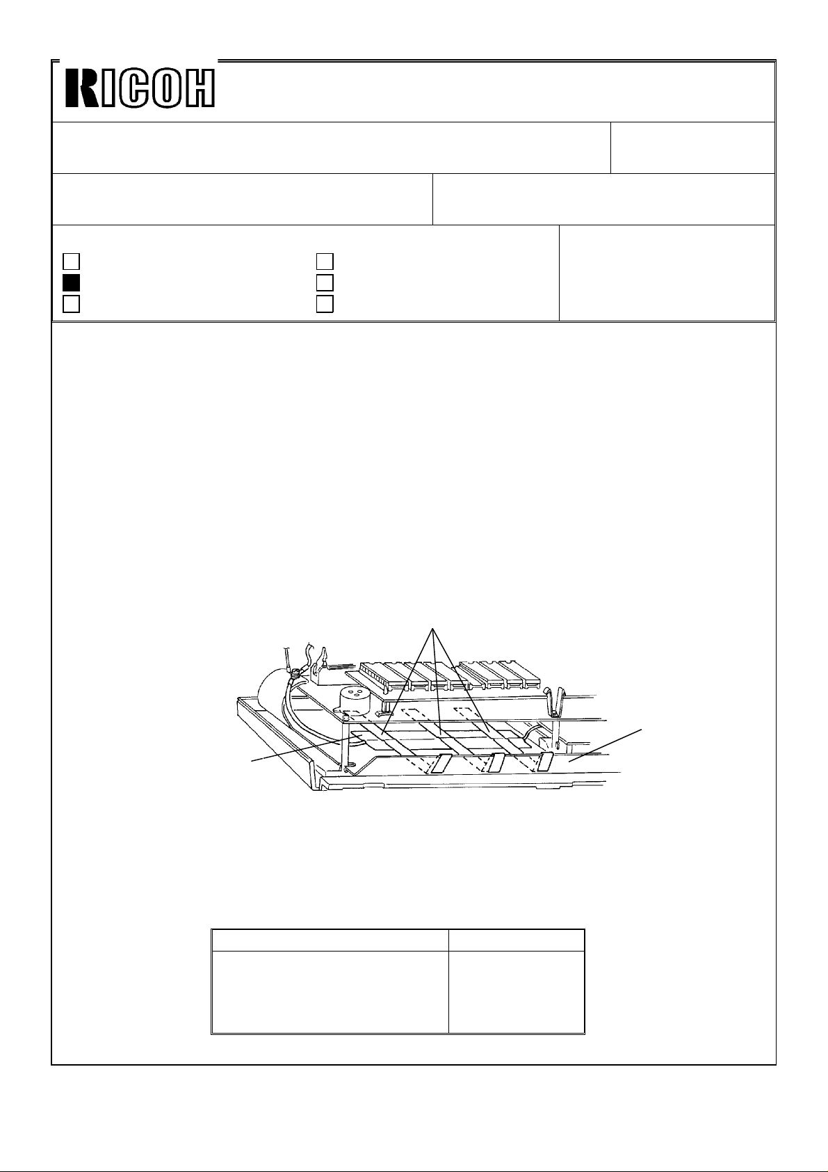
Copper tape stuck on the aluminum sheet below the operation panel control board
peels off partially and touches the operation panel control board.
This condition causes Vcc (5V) to vary. As a result, CPU malfunctions.
3. Action
Secure the copper tape [A] with 3 strips of teflon tape [B] as shown.
The ends of each piece of teflon tape should wrap around the edge of the aluminum
sheet [C].
Revision of service manual
Information only
Other
FROM: Copier Technical Support Sec.
MODEL: F22
[B]
[C]
[A]
4. Countermeasure
The teflon tape strips have been stuck on the copper tape starting with the following
serial number.
Model (V/Hz) Serial No
Savin 9710 (115/60)
Infotec 9172 DZ (220, 240/50)
Ricoh FT7870 (115/60)
Ricoh FT7870 (220, 240/50)
3201200741~
1200001~
2690110221~
2690110311~
Page 2

Technical Bulletin No. RTB-002
SUBJECT: Two-sided copies wrap around the pressure roller DATE: Jan 15. ’91
PAGE: 1 of 1
PREPARED BY: T. Okajima
CHECKED BY:
CLASSIFICATION:
Action Required
Troubleshooting
Retrofit Information
1. Phenomenon
When making the reverse side of a two-sided copy, a paper jam occurs in the fusing
unit. The problem tends to occur in the following situations:
*Solid image on the trailng edge of the 1st side
*Just after installation
*Just after replacing the oil supply pad
2. Cause
Just after installation or replacing the oil supply pad, jams occur because the oil is not
supplied to the pressure roller sufficiently.
3. Action
When installing the machine or replacing the oil supply pad, add oil to the oil supply pad
[A] directly.
Revision of service manual
Information only
Other
FROM: Copier Technical Support Sec.
MODEL: F22
[A]
Page 3
REVISED ON FEB.28
Technical Bulletin No. RTB-003
SUBJECT: Scanner malfunctions ← correction
PREPARED BY: T. Okajima
CHECKED BY:
CLASSIFICATION:
Action Required
Troubleshooting
Retrofit Information
1. Phenomenon
*The scanner suddenly starts moving
*The machine suddenly initializes the lens position.
*The lens stops at an improper position and the copy image becomes dim and
unfocused.
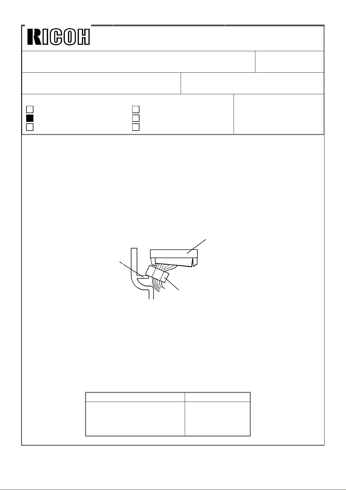
2. Cause
When replacing the upper front cover (below the operation panel), a rib [A] inside this
cover pushes against the core of the DC harness [B]. As a result, CN101 (34 pins) [C]
is disconnected or loosened, and some signals are not sent.
Revision of service manual
Information only
Other
FROM: Copier Technical Support Sec.
MODEL: F22
DATE: Jan 15. ’91
PAGE: 1 of 1
[C]
[A]
[B]
3. Action
Connect CN101 (34pins) on the operation panel PCB.
4. Counter Measure
The rib near CN101 has been removed starting with the following serial numbers:
Model (V/Hz) Serial No
Savin 9710 (115/60)
Infotec 9172 DZ (220, 240/50)
Ricoh FT7870 (115/60)
Ricoh FT7870 (220, 240/50)
3201200741~
1200001~
2690120001~
2690120366~
Page 4

Technical Bulletin No. RTB-004
SUBJECT: Blank Copy DATE: Jan 15. ’91
PAGE: 1 of 1
PREPARED BY: T. Okajima
CHECKED BY:
CLASSIFICATION:
Action Required
Troubleshooting
Retrofit Information
1. Symptom
Just after installing the machine or during the first few days after installation, the
following problem occurs.
Occurs
• Some blank copies are made during repeating copy mode.
• The exposure lamp stops lighting during free run mode.
2. Cause
During transportation of this machine, the 2nd scanner carriage may have been
dislodged from its vertical position on the rod, because of vibration. So, the 2nd carriage
cannot move smoothly.
Revision of service manual
Information only
Other
FROM: Copier Technical Support Sec.
MODEL: F22
[A]
[B]
3. Action
1. Loosen the two screws [A],
2. Move the scanner unit [B] into place and back 4 or 5 times by hand.
3. Fix the two screws which were loosened in step 1.
Page 5

REVISED ON FEB. 28.
Technical Bulletin No. RTB-005
SUBJECT: Sorter Stapler Misfeed DATE: Jan. 31, ’91
PAGE: 1 of 3
PREPARED BY: T. Okajima
CHECKED BY:
CLASSIFICATION:
Action Required
Troubleshooting
Retrofit Information
1. PHENOMENON
This problem occurs only on the sorter stapler with the F22.
The final copy stops at the exit sensor of the sorter stapler in normal copy mode (without
sort/stack mode). When this happens, the jam indicator fails to blink.
The occurence ratio is low because this problem occurs only under the following conditions:
1) Paper with insufficient stiffness is used.
2) The sorter stapler exit sensor bounces.
Revision of service manual
Information only
Other
FROM: Copier Technical Support Sec.
MODEL:
Sorter stapler with F22
Exit sensor
F22
Sorter Stapler
Page 6
Technical Bulletin No. RTB-005
SUBJECT: Sorter Stapler Misfeed DATE: Jan. 31, ’91
PAGE: 2 of 3
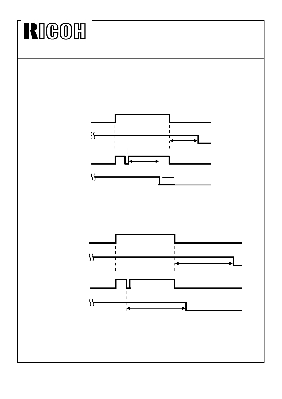
2. CAUSE
The exit sensor feeler tends to bounce when the paper is passing the feeler, and the
sensor briefly turns off.
The CPU of the sorter stapler mistakenly recognizes that the paper has exited into the tray.
Consequently, sorter stapler motor stops before the paper exits completely. (The motor
stops 0.3s after the exit sensor turns off.)
Normal
With
Bounce
Exit Sensor
Motor
Exit Sensor
Motor
ON
OFF
ON
OFF
ON
OFF
ON
OFF
Bounce
0.3s
0.3s
Copy paper stops.
3. ACTION (Program change)
The time interval [A] has been increased from 0.3s to 0.7s. Laboratory tests have show
that even if the exit sensor feeler bounces, this prevents the motor from stopping before
the copy paper exits.
Normal
Exit Sensor
ON
OFF
With
Bounce
Motor
Exit Sensor
Motor
ON
OFF
ON
OFF
ON
OFF
A: 0.7s
A: 0.7s
Page 7

Technical Bulletin No. RTB-005
SUBJECT: Sorter Stapler Misfeed DATE: Jan. 31, ’91
PAGE: 3 of 3
Cut-in serial no. Cut-in ROM part no.
A469 -15 # 312010001 ∼ # A4695103A ∼
-16 # 112010001 ∼
-17 # 244010001 ∼
-25 # 122010006 ∼
-27 # 244010009 ∼
-55 # 282010001 ∼
Correction
P.S.
The latest version of the ROM is P/N A4695103B, which replaces P/N A4695103A.
A paper jam will be detected with the old ROM if the copy paper slips and stops moving
forward for 0.1 msec or more in the sorter stapler connector unit.
The jam check interval of the new ROM (suffix B) has been lengthened by 0.1 msec to
reduce the possibility of the paper jam mentioned above.
Page 8

Technical Bulletin No. RTB-006
SUBJECT: Fusing unit adjustment DATE: Jan. 31, ’91
PAGE: 1 of 2
PREPARED BY: T. Okajima
CHECKED BY:
CLASSIFICATION:
Action Required
Troubleshooting
Retrofit Information
1. SUMMARY
The fusing unit performs less effectively after starting up on a cold morning, when thick
copy paper is used, after operating continuously for a long period of time.
The F20 series copier can be adjusted by SP mode to improve fusing unit performance.
2. ACTION
2-1 Fusing Idling Mode
SP3-3 20 Minutes Fusing Timer FIDL
Revision of service manual
Information only
Other
FROM: Copier Technical Support Sec.
MODEL:
F20, F21, F22
<Function>
The machine idles for 20 minutes after completion of the warm-up cycle. This heats up the
fusing unit.
<Remark>
The machine performs no idling in regular mode.
2-2 Fusing Temperature
SP34 Fusing Temperature
<Function>
The fusing temperature can be adjusted up or down in 16 steps.
1 step = 1.4°C.
Total temperature change = 22.4°C
Standard setting + step 8
See page 3-53 of F20 S/M
page 5-52 of F21 S/M
page 15-6 of F22 S/M.
Page 9

Technical Bulletin No. RTB-006
SUBJECT: Fusing unit adjustment DATE: Jan. 31, ’91
PAGE: 2 of 2
2-3 Fusing Pressure Adjustment
See page 3-51 of the F20 S/M
page 5-50 of the F21 S/M
page 15-11 of the F22 S/M.
NOTE: These adjustments increase power consumption and increase the load on the
machine and are to be done only if the customer is dissatisfied with fusing unit
performance.
Page 10
Technical Bulletin No. RTB-007
SUBJECT: Service call 1 - Exposure DATE: Feb. 28, ’91
PAGE: 1 of 1
PREPARED BY: Takaharu Okajima
CHECKED BY:
CLASSIFICATION:
Action Required
Troubleshooting
Retrofit Information
1. Summary
SC - 1 cannot be cancelled by pressing the SC reset button. This prevents the customer
from just by passing a potentially serious problem. However, when SC - 1 occurs as a
result of electrical noise or some other electrical error, the service representative has to
visit the customer’s office and reset the machine.
We modified the software of the main ROMs so that SC - 1 is less likely to be triggered
by electrical noise.
2. Contents of the modification
If the main board detects an abnormal signal from the lamp regulator lasting 5 ms or
longer, SC - 1 is displayed. The new software extends this detection time from 5 ms to
15 ms, and this reduces occurence ration of the aforementioned problem.
Revision of service manual
Information only
Other
FROM: Copier Technical Support Section
MODEL:
F22
3. Cut in numbers
Parts numbers
P/N A058 7056E : EPROM - 0 - LT
P/N A058 7057E : EPROM - 1 - LT
P/N A058 7156E : EPROM - 0 - A4
P/N A058 7157E : EPROM - 1 - A4
Cut in serial numbers
A058 - 15 ; #3201200923 ∼
A058 - 17 : #2690120001 ∼
A058 - 26 : #12000001 ∼
A058 - 27 : #2690120366 ∼
Page 11
Technical Bulletin No. RTB-008
SUBJECT: Friction Tabs’ Pressure Adjustment in ADF DATE: Apr 15, ’91
PAGE: 1 of 2
PREPARED BY: T. OKAJIMA
CHECKED BY:
CLASSIFICATION:
Action Required
Troubleshooting
Retrofit Information
Revision of service manual
Information only
Other
FROM: Copier Technical Support Sec.
MODEL: F21, F22
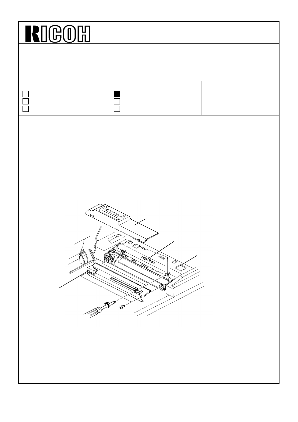
1. Summary.
Add this information to the ADF section of the F21 and F22 service manuals. Since this
adjustment procedure was not explained in these manuals, please read the following
carefully:
Perform this adjustment when:
1. The friction tabs or the separation rollers are replaced.
2. The originals are multi-fed even if the friction tabs and the separation rollers are
cleaned.
[B]
[D]
[C]
[A]
2. Adjustment Procedure.
1. Remove left cover [A] (2 screws), and then remove top cover [B] (2 screws).
2. Close pressure unit [C] and loosen screw [D].
Page 12
Technical Bulletin No. RTB-008
SUBJECT: Friction Tabs Adjustment DATE: Apr 15, ’91
PAGE: 2 of 2
[E]
[G]
[F]
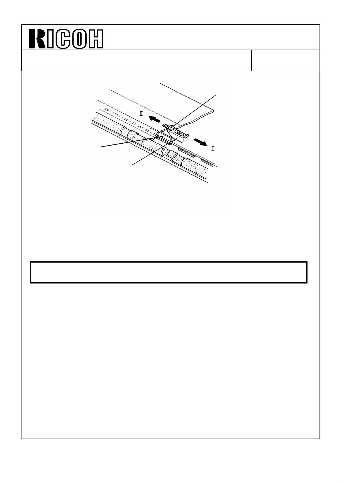
3. Slide screw [E] in the direction of arrow l (illustration) and slide screw [E] towards arrow
ll until blade stopper [F] touches the friction tab’s bracket [G]. Then tighten the screw.
4. Confirm that the originals are fed correctly.
5. Reassemble.
CAUTION If the problems with original skews, misfeeds or double feeds can not
be solved, replace both the friction tabs and the separation rollers.
For your information:
1. When sliding screw [E] in the direction of arrow I, the pressure of the friction tabs
becomes weak.
2. When sliding screw [E] in the direction of arrow II the pressure of the friction tabs
becomes strong.
Page 13

Technical Bulletin No. RTB-009
SUBJECT: Platinum Corona Wire DATE: Apr. 15, ’91
PAGE: 1 of 2
PREPARED BY: H. Kobayashi
CHECKED BY:
CLASSIFICATION:
Action Required
Troubleshooting
Retrofit Information
The following platinum corona wires have been registered as service parts. The tungsten
corona wires are currently being installed on the assembly line, but they may be replaced
in the field with the platinum corona wires, if desired.
Platinum
corona P/N
#52199540 Corona Wire (1 pc/set) #52199101
#A0079540 Main Corona Wire (1 pc/set) #A0089001
#A0079541 PQC Corona Wire (1 pc/set) #A0079002
#A0079542 Transfer Corona Wire (1 pc/set) #A0079003
Revision of service manual
Information only
Other
Description Current Tungsten Corona P/N
FROM:Copier Technical Support Section
MODEL: F22
The platinum and the tungsten corona wires are fairly similar in performance and handling;
however, there are the following differences:
Point 1
During the copy cycle, less foreign matter (toner, dust, gas) will build up on the surface of
a platinum corona wire than on a tungsten wire. Consequently, platinum corona wires do
not need to be cleaned as often to maintain copy quality. This is true for both these
platinum corona wires and the third vendor’s platinum corona wires.
Point 2
Negative charges cause portions of the surface of a platinum corona wire to break off,
affecting the copy image and requiring replacement of the wire. A platinum wire cannot be
used as a negative charge corona. (A tungsten wire can be used as a negative charge
corona wire.) This is true for both these platinum corona wires and the third vendor’s
platinum corona wires.
Page 14

Technical Bulletin No. RTB-009
SUBJECT: Platinum Corona Wire DATE: Apr. 15, ’91
PAGE: 2 of 2
--When to install the platinum corona wires-
The platinum corona wires do not have to be cleaned as often as the tungsten wires
(point 1). For this reason, the platinum corona wires are most suitable in cases where a
machine is installed in a relatively inaccessible location (far from a service center) and
service calls are difficult to make.
The platinum wires can be installed in the field on the following models:
Model Main Transfer PQC PCC Separation PTC
F20
F21
F22
F30
F31
F33
F34
F40
#52199540 #52199540 #52199540 Negative
charge.
Do not use.
#A0079540 #A0079542 #A0079541 Negative
charge.
Do not use.
Negative
charge.
Do not use.
Negative
charge.
Do not use.
Negative
charge.
Do not use.
Not used.
Note 1
When installing the platinum corona wires, please take the following actions:
1. Clean the corona casings, end blocks, and new platinum wires with damp cloth.
2. Confirm VSG.
Note 2
#A0079540 can also be used as the F90 main corona wire.
Page 15

Technical Bulletin No. RTB-010
SUBJECT: Blank Copy DATE: May 31, ’91
PAGE: 1 of 2
PREPARED BY: T. Okajima
CHECKED BY:
CLASSIFICATION:
Action Required
Troubleshooting
Retrofit Information
1. Summary
After installation, the F22 would sometimes produce blank copies during multiple copying.
We issued RTB-004 (F22) to solve this problem, but we have had reports from affiliated
companies that some machines still sometimes produce blank copies, even after following
the procedure outline in the RTB. Also, we’ve had reports that paper jammed in the
machine because of scanner movement. Here are additional steps to solve these
problems:
2. Adjustments
(1) If the RTB-004 procedure doesn’t fix the paper jam and/or the blank copy problem,
change the SP31 data (scanner brake timing). Change the data from the factory
setting of 8 to the new setting A.
Revision of service manual
Information only
Other
FROM: Copier Technical Support Section
MODEL:
F22
(2) After changing the SP31 data, the copy image registration may change. Check the
copy image and if necessary, adjust the copy image registration with SP32.
3. SP31 factory setting
We now set SP31 to "A" when the machines leave the factory. We’ve put the new setting
beginning with the machines listed in the table below.
Machine Code Volts/Hz Model Name Cut-in Serial Number
A058-15 115/60 Savin 9710 3210301001 ∼
A058-16 115/60 Nashua 4172 252106XXXX ∼
A058-17 115/60 Ricoh FT7870 2691030053 ∼
A058-25 220, 240/50 Nashua 4172 2511040001 ∼
A058-26 220, 240/50 infotec 91720Z 3A60410001 ∼
A058-27 220, 240/50 Ricoh FT7870 2691040116 ∼
Page 16

Technical Bulletin No. RTB-010
SUBJECT: Blank Copy DATE: May 31, ’91
PAGE: 2 of 2
4. Cause of the problem
When making repeat copies, the scanner first has to return to its home position, and it has
to return before the start of the next copy cycle. If it doesn’t, the paper will be fed, but the
scanner won’t be in time, the lamp will not turn on, and the copy process timing will go
out of control causing a blank copy and possibly a paper jam.
To prevent these problems, decrease the total scanning time with SP31.
5. SP31 function
Exposure Glass
Foward
Return
Scanner H.P.
Sensor
1st Scanner
DCBA9 8 7 6 5 4 3
Scanner H.P. is
changed by SP31.
SP31 controls the start position of the first scanner. If we lower the setting, for instance
from 8 to 7, the scanner shifts about 2 mm (0.079 inch) away from the scanner H.P.
sensor. This increases the total scanning time.
On the other hand, if we raise the setting, say from 8 to A, the first scanner shifts about 4
mm (0.158 inch) closer to the H.P. sensor. This will decrease the total scanning time.
Page 17

Technical Bulletin No. RTB-011
SUBJECT: Sorter /sorter stapler installation as a 20 bin, or 40 bin
system
PREPARED BY: I. Kakegawa
CHECKED BY:
CLASSIFICATION:
Action Required
Troubleshooting
Retrofit Information
This RTB clarifies installation of the sorter, sorter stapler, and connector units on the F20,
F21, and F22. Both 20bin and 40 bin systems are covered.
Because the F20, F21, and F22 copy at different speeds, the main PCB ROM on the old
sorter or sorter stapler must be replaced on some types of systems. Therefore, please
read this RTB carefully for F20/F21/F22 system installation.
1. TYPES OF SYSTEM
There are 8 types of F20/F21/F22 systems:
[Sorter System]
Revision of service manual
Information only
Other
FROM: Copier Technical Support Sec.
MODEL: F22
(Same RTB for F21--No.17 and
F20--No.28 are issued.)
DATE: July 15,’90
PAGE: 1 of 8
1) F20 or F21 + one sorter (20 bins) ....................No special action needed.
*2) F20 or F21 + two sorters (40 bins)....................See page 2 and 3.
3) F22 + one sorter (20 bins).................................No special action needed.
*4) F22 + two sorters (40 bins) ...............................See page 2 and 4.
[Sorter Stapler System]
1) F21 + one sorter stapler (20 bins).....................No special action needed.
*2) F21 + two sorter staplers (40 bins)....................See page 5 and 6.
*3) F22 + one sorter stapler (20 bins) .....................See page 5 and 7.
*4) F22 + two sorter staplers (40 bins)....................See page 5 and 8.
NOTE: Systems marked * need to have the ROM replaced if the old sorter or old sorter
stapler is used. Pay special attention to these systems.
Page 18

Technical Bulletin No. RTB-011
SUBJECT: Sorter /sorter stapler installation as a 20 bin, or 40 bin
system
DATE: July 15,’90
PAGE: 2 of 8
2. SORTER SYSTEM
2--1. Modification history for two sorters and connector unit
Model Code Sorter: 5937 -- Sorter: A462 -- Sorter Connector
Unit: 5946 --
Model Name
P/N for
the sorter
ROM
Ricoh CS2060 for F20
Infotec sorter 9060 for F20
Nashua D820 for
F20/21/22.
Savin FS65 for F20/21.
Pitney Bowes D820 for
F20/21
Ricoh CS 2065 for F21/F22
Infotec Sorter 9165 for
F21/22
Savin Sorter for F22
Sorter Connector unit, type A.
Type 1 P/N 59375603 No production No production
Modification (1)
No sorter ROM enclosed in
the accessary box.
One piece of ROM with P/N
59375613 "G" is enclosed.
Type 2
P/N 59375613
from no suffi to "F"
Modification (2) Modification (3)
P/N 59375613
from no suffix to "F"
Type 3 P/N 59375613 "G" P/N 59375613 "G"
Modification (4)
NOTE:
Modification (1) is to adapt the F20/F21 with a 40 bin system from type 2 ROM.
Modification (2) and (3) are to adapt the F22 with a 40 bin system from type 3 ROM.
Modification (4) is to adapt the F22 with a 40 bin system even if old sorters
(type 1, or 2) in stock are used.
As you can see from the above table, there are:
•Three types of sorters for model code 5937
•Two types of sorters for model code A462
•Two types of connector units.
Page 19

Technical Bulletin No. RTB-011
SUBJECT: Sorter /sorter stapler installation as a 20 bin, or 40 bin
system
DATE: July 15,’90
PAGE: 3 of 8
2--2. Necessary action by type of sorter system
[F20 or F21 + two sorters + connector unit (40 bins)]
With this type of system, the action required differs depending on the type of ROM on the
sorter main PCB and by type of the connector unit.
So, please check the part number of ROM and the serial number of the sorter and
connector unit. Then, you can know the type (old or new) of your sorter and connector
unit. For each type, please refer to page 2.
Sorter
[Cut-in serial number for modification (1)]
(From August, ’86 production onward.)
(See Modification (1) )
Old
(Type 1)
Sorter
Connector
Unit
5946--17 Ricoh USA
5946--27 Ricoh Europe
Nashua Europe
5946--27 Infotec 3441200001
Old
(Type 2)
New
(Type 3)
[Cut-in serial number for modification (4)
(From December, ’90 production onward)
Model S/N
Savin
Pitney Bowes
[A] [C]
[B] [D]
(Type 2 and 3)
21105xxxxx
2101200505
New
5937-11(Pitney Bowes) 6080001
5937-15 (Savin) 9460800025
5937-17 (Ricoh, USA) 1660800075
5937-25 (Nashua) 9260800002
5937-26 (Infotec) from first
5937-27 (Ricoh Europe) 1660800036
A462- all models from first
Model S/N
production
production
[A]: Old sorter (Type 1) + Old connector unit (Type 2).
The old ROM (P/N 59375603) on the first sorter main PCB should be replaced with
a new ROM. P/N 59375613, (no suffix or any suffix from A to G) is acceptable.
The ROM is not included, so please prepare one before installation.
[B]: Old sorter (Type 1) + New connector unit (Type 3).
The old ROM (P/N 59375603) on the first sorter main PCB should be replaced with
a new ROM (P/N 59375613G) enclosed in the carton box of the new connector
unit.
[C]: New sorter (Type 2 or 3) + Old connector unit (Type 2).
Since the sorter has a new ROM for 40 bins system, no action is required.
[D]: New sorter (Type 2 or 3) + New connector unit (Type 3).
No ROM replacement is required.
Page 20

Technical Bulletin No. RTB-011
SUBJECT: Sorter /sorter stapler installation as a 20 bin, or 40 bin
system
DATE: July 15,’90
PAGE: 4 of 8
[F22 + two sorters + connector unit (40 bins)]
With this type of system, the action required differs depending on the type of ROM on the
sorter main PCB and by type of the connector unit.
So, please check the part number of ROM and the serial number of the sorter and
connector unit. Then, you can know the type (old or new) of your sorter and connector
unit. For each type, please refer to page 2.
Sorter
(See Modification (2) and (3))
Old
(Type 1and 2)
Sorter
Connector
Unit
5946--17 Ricoh USA
5946--27 Ricoh Europe
5946--27 Infotec 3441200001
Old
(Type 2)
New
(Type 3)
[Cutrin serial number for modification (4)
(From December, ’90 production onward)
Model S/N
Savin
Nashua Canada
Nashua Europe
[A] [C]
[B] [D]
New
(Type 3)
21105xxxxx
2101200505
[Cut-in serial number for modification (2)
and (3)] (From February or March, ’91 production onward)
Model S/N
5937-11(Pitney Bowes) No production
5937-15 (Savin) 94105xxxxx
5937-17 (Ricoh, USA) No production
5937-25 (Nashua) 9210300859
5937-26 (Infotec) No production
5937-27 (Ricoh Europe) No production
A462-15 (Savin) 385106xxxx
A462-17 (Ricoh, USA) 2451020001
A462-26 (Infotec) 3860410001
A462-27 (Ricoh Europe) 2451020046
[A]: Old sorter (Type 1 or 2) + Old connector unit (Type 2).
The old ROM (P/N 59375603, or P/N 59375613 up to suffer "F") on the first sorter
main PCB should be replaced with a new ROM.(P/N 59375613G),
The new ROM is not included, so please prepare one before installation.
[B]: Old sorter (Type 1 or 2) + New connector unit (Type 3).
The old ROM (P/N 59375603, or P/N 59375613 up to suffix "F") on the first sorter
main PCB should be replaced with a new ROM (P/N 59375613G) enclosed in the
carton box of the new connector unit.
[C]: New sorter (Type 3) + Old connector unit (Type 2).
Since the sorter has a new ROM (P/N 59375613G), no action is required.
[D]: New sorter (Type 3) + New connector unit (Type 3).
No ROM replacement is required.
Page 21

Technical Bulletin No. RTB-011
SUBJECT: Sorter /sorter stapler installation as a 20 bin, or 40 bin
system
3. SORTER STAPLER SYSTEM
3--1. Modification history for sorter stapler and connector unit
Sorter Stapler: A469
Type 1
Type 2
Type 3
NOTE: • Modification (1) is to adapt the F21 with a 40 bin system from type 2 ROM.
ROM P/N 4695102 with
suffix form "B" to "E"
Modification (1)
ROM P/N A4695103 (No
suffix)
Modification (2)
ROM P/N A4695103 "A" or
"B"
Serter Stapler Connector
Unit: A310
No Production
Two pieces of ROM with
P/N A3105106A are
enclosed.
Modification (3)
ROM P/N A4695103A or B
DATE: July 15,’90
PAGE: 5 of 8
• Modification (2) is to adapt the F22 with either a 20 bin or a 40 bin system from
type 3 ROM.
• Accessory ROMs (P/N A3105106A) in the connector unit (type 2) are used
when the old sorter staplers (type 1) are installed on the F21 as a 40 bin
system.
(P/N A3105106A has the same program as P/N A4695103 with no suffix.)
• Modification (3) is to adapt the F22 with a 40 bin system even if old sorters
(type 1 and 2) are used.
As you can see from the above table, there are ;
•Three types of sorter staplers
•Two types of connector units
Page 22

Technical Bulletin No. RTB-011
SUBJECT: Sorter /sorter stapler installation as a 20 bin, or 40 bin
system
DATE: July 15,’90
PAGE: 6 of 8
3--2. Necessary action by type of sorter stapler system
[F21 + two sorter staplers + connector unit (40 bins)]
In this system, an action required is different by type of ROM on the sorter stapler main
PCB and by type of the connector unit.
So, please check the part number of ROM and the serial number of sorter stapler and
connector unit. Then, you can know the type (old or new) for your sorter stapler and
connector unit. For each type, please refer to page 5.
Sorter stapler
Old
(Type 1)
Old
Connector
Unit
A310--17 115V/60Hz 2670100001
A310--27 220, 240V/50Hz 2680100001
(Type 2)
New
(Type 3)
[Cut-in serial number for modification (3)
(From October, ’90 onwards)
Model S/N
[A] [C]
[B] [D]
(Type 2 and 3)
New
[Cut-in serial number for modification (1)]
(From June, ’90 production onward.)
Model S/N
A469-11 (Pitney Bowes) 0060001
A469-15 (Savin) 3120060001
A469-16 (Nashua
Canada)
A469-17 (Ricoh, USA) 2440060001
A469-25 (Nashua Europe) 1220070006
A469-26 (Infotec) 383090xxxx
A469-27 (Ricoh Europe) 2440060342
A469-55 (Savin) From the first
M/B Sorter Stapler No 20
issued on Aug- 31,’90)
1220060001
production
[A]: Old sorter stapler (Type 1) + Old connector unit (Type 2).
The old ROM (P/N A4695102B to E) on the sorter stapler main PCB should be
replaced with the ROMs enclosed in the sorter stapler connector unit (P/N
A3105106A).
[B]: Old sorter stapler (Type 1) + New connector unit (Type 3).
The old ROM (P/N A4695102B to E) on the sorter stapler main PCB should be
replaced with the ROMs enclosed in the sorter stapler connector unit (P/N
A4695103A or B).
[C]: New sorter stapler (Type 2 or 3) + Old connector unit (Type 2).
Since the sorter stapler main PCB already has a new ROM (P/N A4695103), it is
not necessary to replace it.
[D]: New sorter stapler (Type 2 and 3) + Old connector unit (Type 3).
Same as [C].
Page 23

Technical Bulletin No. RTB-011
SUBJECT: Sorter /sorter stapler installation as a 20 bin, or 40 bin
system
[F22 + one sorter stapler (20 bins)]
•See RTB F22 No 5.
•When an old sorter stapler (type 1 and 2) is installed on the F22, a new ROM (P/N
A4695103A or B) is required. Prepare a new ROM and replace the old ROM on the
sorter stapler main PCB (P/N A4695102B to E, or A4695103 with no suffix) with a
new ROM (P/N A4695103A or B, P/N A4695103A or B).
•Cut-in serial number for modification (2)
(From October, ’90 production anward.
Model Name V/Hz Code S/N
Pitney Bowes D962 115V/60 Hz A469-11 011xxxx
Savin 7640 S/F 115V/60 Hz A469-15 3120100001
Nashua SR 4965 115V/60 Hz A469-16 1220100001
Ricoh ST 20 115V/60 Hz A469-17 2440100001
Nashya SR 4965 220, 240V/50 Hz A469-25 1220100006
Infotec S/S 9165 220, 240V/50 Hz A469-26 3831100001
Ricoh ST 20 220, 240V/50 Hz A469-27 2440100001
Savin 9710 S/F 115V/60 Hz A469-55 2820100001
DATE: July 15,’90
PAGE: 7 of 8
From the above S/N, a new ROM (P/N A4695103A) has been used at the
factory.
Page 24

Technical Bulletin No. RTB-011
SUBJECT: Sorter /sorter stapler installation as a 20 bin, or 40 bin
system
[F22 + two sorter staplers + connector unit (40 bins)]
Sorter stapler
Connector
Unit
[Cut-in serial number for modification (3)]
Old
(Type 2)
New
(Type 3)
Old
(Type 1 and 2)
[A] [C]
[B] [D]
New
(Type 3)
Cut-in serial number for
modification (2):
See the table in page 7.
(From October,’90 production onward.)
Model S/N
A310--17 115V/60Hz 2670100001
A310--27 220, 240V/50Hz 2680100001
[A]: Old Sorter stapler (Type 1 and 2) + Old connector unit (Type 2).
Prepare two new ROMs (P/N A4695103A or B) and replace the old ROM on each
sorter stapler main PCB with a new one.
DATE: July 15,’90
PAGE: 8 of 8
[B]: Old sorter stapler (Type 1 and 2) + New connector unit (Type 3).
The old ROM on the sorter stapler main PCB should be replaced with the new
ROM (P/N A4695103A or B) enclosed in the new connector unit.
[C]: New sorter stapler (Type 3) + Old connector unit (Type 2).
Since the sorter stapler has a new ROM (P/N A4695103A or B), the old ROMs
(P/N A3105106A) in the old connector unit should not be used. Keep the original
new ROM on the sorter stapler main PCB.
(If it is replaced, paper jam in the sorter stapler may occur.)
[D]: New sorter stapler (Type 3) + New connector unit (Type 3).
Since the sorter stapler has a new ROM (P/N A4695103A or B), ROM replacement
is not necessary.
NOTE:
You can keep the two new accessory ROMs (P/M A4695103A) for these systems as
spare ROMs ;
•F22 + old sorter stapler (type 1 or 2) for 20 bins, or
•F22 + two old sorter staplers (type 1 or 2) + old connector unit.
Page 25

Technical Bulletin No. RTB-012
SUBJECT: Software quality improvement DATE: July 31, ’91
PAGE: 1 of 4
PREPARED BY: T. Okajima
CHECKED BY:
CLASSIFICATION:
Action Required
Troubleshooting
Retrofit Information
Revision of service manual
Information only
Other
FROM: Copier Technical Support Section
MODEL:
F22
1. Summary
We have received some reports of this problem and have encountered independently as
well. So, we have modified the software in the main ROM on the main PCB to solve the
following items,
1) Computer Form is not fed in the CFF mode.
2) Originals are not fed in the user program mode.
3) Jitter image appears on the trailing edge of A4 or Letter size in full size mode.
2. Details
1) CFF mode does not work
Problem
When the computer form paper is set on the exposure glass, the DF cover is lowered and
the start key is pressed, one copy is made but the computer form paper is not fed at all.
Cause
The main PCB cannot get the CFF set signal due to noise.
Countermeasure
When a computer form is set in the computer form feeder and the DF cover is lowered,
the main PCB checks the CFF set signal only once. To ensure detection of set signal, we
have modified the software to check the CFF set signal twice.
Page 26

Technical Bulletin No. RTB-012
SUBJECT: Software quality improvement DATE: July 31, ’91
PAGE: 2 of 4
2) Originals are not fed in the user program mode
Problem
Originals are not fed when these steps are followed in this order:
1. Insert originals into the document feeder.
2. Recall one of the program numbers (1 to 5).
3. Enter the number of copies required.
4. Press the start key.
Cause
In the present software for program mode, not only copy modes except copy number but
also DF or platen mode are stored. (When originals are in the feed-in unit of the DF while
storing the user program, the DF mode is stored. On the other hand, when originals are
not in the feed-in unit of the DF while storing the user program, the platen mode is stored.)
In many cases, the above key operation will result in platen mode copy due to this reason.
Countermeasure
The software for program mode has been changed, so that DF or platen mode could not
be stored.
NOTE: To prevent this mode without the ROM replacement, please instract the customer
as follows:
First, press the recall key and enter the number of copies. And, then set the
original to the DF.
Page 27

Technical Bulletin No. RTB-012
SUBJECT: Software quality improvement DATE: July 31, ’91
PAGE: 3 of 4
3) Jitter image
Problem
2 or 3 mm band jitter image may appear on the trailing edge of A4/Letter size paper.
Feed
Trailing Edge
Normally, this band is erased by the trailing edge erase function. However, if the width of
the erase area is narrow, the jitter image appears.
Cause
The scanner speed of this machine is higher than that of the F21, F20. If the scanner
movement is slightly heavy, the scanner will start braking within the image area.
Countermeasure
The scanner brake timing has been delayed 3 mm at the trailing edge. So, A4/letter image
is completely scanned.
In RTB-F22-010, we informed you of how to use SP31 (Scanner brake timing) and that the
data setting "A" has been set at the factory. So, do not change the data "A". If the data "A"
is chaged to "9" or "8", blank copies or paper jams may occur easily.
Jitter image
2 ∼ 3 mm
NOTE: Make sure that SP31 data is set at "A", since scanning time is increased due to
this new program.
If "9" or smaller data is set, blank copy or paper jam will occure.
If "B" or greater data is set, jitter is observed at the leading edge of copy.
Page 28

Technical Bulletin No. RTB-012
SUBJECT: Software quality improvement DATE: July 31, ’91
PAGE: 4 of 4
3. Action
If you have the problem which is described in section 2, replace the ROMs on the main
PCB with the ROMs (suffix "F").
New ROM for 115 V, 60 Hz model
ROM 0 P/N A0587056F
ROM 1 P/N A0587057F
New ROM for 220/240 V 50 Hz model
ROM 0 P/N A0587156F
ROM 1 P/N A0587157F
4. Cut-in serial number
Machine Code Volts/Hz Model Name Cut-in Serial number
A058-15 115/60 Savin 9710 32107XXXXX ∼
A058-16 115/60 Nashua 4172 252107XXXX ∼
A058-17 115/60 Ricoh FT7870 2691060001 ∼
A058-25 220, 240/50 Nashua 4172 2511060001 ∼
A058-26 220, 240/50 infotec 91720Z 3A60610001 ∼
A058-27 220, 240/50 Ricoh FT7870 2691060233 ∼
Page 29

Technical Bulletin No. RTB-013
SUBJECT: F21/F22+two sorter staplers+menu reader DATE: 30 Sep. ’91
PAGE: 1 of 2
PREPARED BY: T. Okajima
CHECKED BY:
CLASSIFICATION:
Action Required
Troubleshooting
Retrofit Information
1. Summary
We have received reports of a software problem. This problem occurs under the
following condition only.
1) Machine combination
•F21 or F22
•2 sorter staplers (40bins)
•Sorter stapler connector
•Menu reader
Revision of service manual
Information only
Other
FROM: Copier Technical Support Section
MODEL: F22
(Same RTB for F21-018)
2) Mode
When operating the machine by using the menu reader. (the problem does not occur
when using the operation panel).
3) Problem
The problem is that the copy papers are fed into the trays at random
4) Action
When you install the machines above combination, please replace the main ROMs in
the copier with the new one.
Page 30

Technical Bulletin No. RTB-013
SUBJECT: F21/F22+two sorter staplers+menu reader DATE: 30 Sep. ’91
PAGE: 2 of 2
2. New ROMs
Please replace the main ROMs (2 pcs) in the copier with the following:
F21 115V/60HZ
Label Check Sum
A0296211D Special 84 A529
A0296212E Special 84 DAA3
F21 220, 240V/50HZ
Label Check Sum
A0296211D Special 84 A529
A0296222E Special 84 02A5
F22 115V/60HZ
Label Check Sum
A0587056F Special 82 4A66
A0587057F Special 82 3BA5
F22 220, 240V/50HZ
Label Check Sum
A0587156F Special 82 4A66
A0587157F Special 82 994D
3. Cut-in serial number
The cut-in serial numbers and the production ROM numbers will be sent to you later.
Page 31

Technical Bulletin No. RTB-014
SUBJECT: Software improvement DATE: Apr. 30, ’92
PAGE: 1 of 4
PREPARED BY: Takaharu Okajima
CHECKED BY:
CLASSIFICATION:
Action Required
Troubleshooting
Retrofit Information
1. Summary
We have received reports of a software problem. So, we have modified the software in
the main ROM. For details, please read the following carefully:
2. Details
1) F21/F22 + two sorter stapler units + menu reader
Problem
In the combination above, when operating the machine by using the menu reader, the
copies will be sorted into the bins at random. (The problem does not occur when using the
operation panel.)
Action
We have corrected the software.
Revision of service manual
Information only
Other
FROM: Copier Technical Support Group
MODEL: F22
(Same RTB for F21-020)
2) Toner marks
Problem
After multi-copying for a long time, toner marks appear at the position where the pick-off
pawls are located.
Cause
During A4/LT or smaller size multi-copy runs, the pick-off pawls continuously touch the
drum, and the toner around the drum accumulates on the pick-off pawls. After many
copies (depending on the copy image) the toner on the pawls drops on the paper.
On the other hand, when A3 (DLT) paper is used, the pick-off pawls are repeatedly
turned off and on, and the toner will not accumulate on the pawls.
See details, next page.
Page 32

Technical Bulletin No. RTB-014
SUBJECT: Software quality improvement DATE: Apr. 30, ’92
PAGE: 2 of 4
F20/F21/F22
A
Regist. MC
ON
OFF
Depending on
the paper size
B
Pick-off
Pawls Sol.
ModelA(One cycle time for
F20 See table 2 89 ms 800 ms 889 ms
F21 See table 2 90 ms 910 ms 1000 ms
F22 See table 2 141 ms 820 ms 961 ms
ON
OFF
multi-copying)
(Fixed)
(Lead time for pick-off
pawls sol. ON)
1st copy 2nd copy
Depending on
the paper size
B
C
(Fixed) (Fixed) (Fixed)
B
(pick-off pawls sol. ON
C
time)
A
C
Table 1
B + C
Model
F20 1500 952 857 1500 952 857
F21 1463 923 833 1463 938 833
F22 1333 833 811 1333 845 811
A3 A4 A5 DLT LT HLT
A (One cycle time for multi-copying) ms
Table 2
D
D
The pick-off pawls solenoid will be turned on after time "B" from turning on the registration
MC. (Time "B" is fixed by model.) See table 1. The pick-off pawls solenoid is turned on for
time "C" to ensure paper separation. (Time "C" is fixed by model.) Then, this will be turned
off. See table 1. However, during multi-copy run and when one cycle time "A" is shorter
than time "B + C", the pick-off pawls solenoid cannot be turned off. The time "C" is higher
priority than time "B". So, time "B" is cancelled, in this case.
To turn the pick-off pawls solenoid on and off repeatedly, "A" should be 50 ms longer than
"B + C". This is for mechanical reasons.
Page 33

Technical Bulletin No. RTB-014
A
SUBJECT: Software quality improvement DATE: Apr. 30, ’92
PAGE: 3 of 4
3. Countermeasure
2nd copy
Regist. MC
B
Pick-off Pawls Sol.
New ROM: During multi-copy runs, the pick-off pawls solenoid will be off during each
copy cycle for any sizes of copy paper. First, after B ms from turning on the
registration clutch, the pick-off pawls solenoid is turned on. And when the
registration clutch is turned off, the pick-off pawls solenoid is also turned off.
After B msec from turning on the registration clutch, the pick-off pawls
solenoid will be turned on for the next copy.
New ROM Parts number and check sum:
F21 115V version
ROM 0 P/N A0296211E Check sum: A529
ROM 1 P/N A0296212F Check sum: DAA3
F21 220/240V version
ROM 0 P/N A0296211E Check sum: A529
ROM 1 P/N A0296222 ECheck sum: 02A5
F22 115V version
ROM 0 P/N A0587056G Check sum: 4A8C
ROM 1 P/N A0587057G Check sum: 45AB
B
B ; 160 ms
F22 220/240V version
ROM 0 P/N A0587156G Check sum: 4A8C
ROM 1 P/N A0587157G Check sum: A369
4. Action
If you have this problem, replace the ROMs with new one and clean the solenoid shaft
of the pick-off pawls with alchol.
Page 34

Technical Bulletin No. RTB-014
SUBJECT: Software quality improvement DATE: Apr. 30, ’92
PAGE: 4 of 4
5. Cut-in serial number
MODEL NAME V/Hz DESTINATION CODE SERICAL NUMBER
Savin 9710 115/60 USA A058-15 3220301772
Nashua 4172 115/60 Canada A058-16 2521120001
Ricoh FT7870 115/60 USA A058-17 2691120296
Nashua 4172 220, 20/50 Europe A058-25 2511120001
infotec 9172DZ 220, 20/50 Europe A058-26 3A6042XXXX
Ricoh FT7870 220, 20/50 Europe A058-27 2691120441
MODEL NAME V/Hz DESTINATION CODE SERICAL NUMBER
P.B. D964 115/60 USA A029-11 204XXXX
P.B. D964 115/60 Canada A029-12 204XXXX
Savin 7640 115/60 Canada A029-14 712040XXXX
Savin 7640 115/60 USA A029-15 712040XXXX
Nashua 4965 115/60 Canada A029-16 Service Parts only
Ricoh FT7770 115/60 USA A029-17 Service Parts only
Ricoh FT7770 115/60 Canada A029-19 Service Parts only
Nashua 4965 220, 240/50 Europe, etc A029-25 Service Parts only
infotec 9165DZ 220, 240/50 Europe A029-26 382042XXXX
Ricoh FT7770 220, 240/50 Europe, etc A029-27 Service Parts only
Page 35

Technical Bulletin No. RTB-015
SUBJECT: Software quality improvement DATE: Sep. 30, ’92
PAGE: 1 of 2
PREPARED BY: T. Okajima
CHECKED BY:
CLASSIFICATION:
Action Required
Troubleshooting
Retrofit Information
Revision of service manual
Information only
Other
FROM: Copier Technical Support Section
MODEL:
F22
1. Summary
We have received some reports of the following software problems and have encountered
it independently as well. So, we have modified the software in the main ROM on the main
PCB:
1) Incorrect erasing at 103% enlargement on Letter size ( 8.5"x11") copies
2) Toner end operation
3) Void area on the leading edge of 11"x17" size copy
2. Details
1) Incorrect erasing at 103% enlargement on Letter size ( 8.5"x11") copies
Problem
For the 220-240V version machine, when enlarging to 103% on letter size copies, half of
the copy image is missing.
Cause
Only for 103% enlargements on letter size copies, the erase lamp erases half of the copy
image. This is a software error.
Countermeasure
The software has been modified.
2) Toner end operation
Problem
Even if the toner end indicator is lit, the machine can be operated immediately by just
turning the main switch off and on. After making a few hundred copies in this condition, the
carrier will be damaged due to too low toner concentration.
Countermeasure
The toner end operation has been changed as follows:
When the toner end indicator is lit and the main switch is turned off and on, the machine
goes in the toner supplying mode ( toner supply clutch and development motor on) for 40
sec. After that, the print key becomes green. We supposed that the operator would replace
the toner cartridge with a new one, because the operator has to wait 40 sec after turning
the main switch off and on in the toner end condition.
Page 36

Technical Bulletin No. RTB-015
SUBJECT: Software quality improvement DATE: Sep. 30, ’92
PAGE: 2 of 2
3) Void area on the leading edge of 11"x17" size copy
Problem
Void area appears on place 110mm from the leading edge of 11"x17" size copy.
Cause
The paper buckle is little larger than the specification when the paper is fed from the 1st
tray, the 2nd tray, and the duplex tray. So, the copy paper has a wrinkle at the place
mentioned above.
Countermeasure
The paper buckle is decreased as follows:
The paper from the duplex tray: minus 3.0mm
The paper from the 1st feed tray: minus 2.1mm
The paper from the 2nd feed tray: minus 1.7mm
The paper from the large capacity tray: same as before
3. ROMs and cut-in serial number
Part
number
A0587056H Main EPROM 0 2 243 Savin 9710 115/60 3220501811
A0587057H Main EPROM 1 5CE1 Ricoh FT7870 115/60 2522050001
A0587156H Main EPROM 0 2243 infotec 9172DZ 2 30/50 2512 060001
A0587157H Main EPROM 1 BAB3 Nashua 4172 230/50 3A6082xxxx
A0587126A Main EPROM 0 2249 Minolta EP97 20 115/ 60 36 000611
A0587127A Main EPROM 1 5CE1
A0586384A Main EPROM 0 2240 Toshiba 7110 115/60 30421081
A0586385A Main EPROM 1 5CE1
ROM capacity: 256Kbit
Description Check sum Model name V/Hz Cut-in serial no.
Nashua 4172 115/60 2692050001
Ricoh FT7870 230/50 2692070001
4. Action taken
When you have a problem mentioned above, replace the ROMs with new one as a set.
Page 37

Technical Bulletin No. RTB-016
*82
*96
*92
SUBJECT: Replacement adjustment for Stapler Unit Component part DATE: Oct. 15, ’93
PAGE: 1 of 3
PREPARED BY: T. Okajima
CHECKED BY:
CLASSIFICATION:
Action Required
Troubleshooting
Retrofit Information
1. Summary
We have registered some component parts of the stapler unit (#AJ011001) at our service
parts center to meet a field request. See MB-28 of the F21 and F22 sorter stapler for
further details.
See the illustration and the part number table that follow. In section 2 of this RTB we
describe the replacement and adjustment of some parts, that you need to pay attention to.
*83
*84
*95
Revision of service manual
Information only
Other
FROM: Technical Support Department
MODEL: F22
Sorter Stapler for F22
*93
*94
*91
*90
*85
*86
*87
*88
*89
Page 38

Technical Bulletin No. RTB-016
SUBJECT: Replacement adjustment for Stapler Unit Component part DATE: Oct. 15, ’93
PAGE: 2 of 3
Parts No. Description Q’ty
A4699502 Spring - Stapler Unit 2 *82 15
A4699503 Clamp - Cartridge Holder 1 *83 15
A4699504 Wire - Cartridge Holder 1 *84 15
A4699505 Motor Gear 1 *85 15
A4699506 Gear 1 1 *86 15
A4699507 Gear 2 1 *87 15
A4699508 Key - Drive Gear 1 *88 15
A4699509 Drive Gear 1 *89 15
A4699510 Gear Holder 1 *90 15
A4699511 Pin - Plate 1 *91 15
A4699512 Face Plate 1 *92 15
A4699513 Drive Plate 1 *93 15
A4699514 Forming Plate 1 *94 15
A4699515 Pin - Cartridge Holder 1 *95 15
A4699516 Roller - Cartridge Holder 1 *96 15
Parts catalog
Index Page
* New Index No.
Page 39

Technical Bulletin No. RTB-016
SUBJECT: Replacement adjustment for Stapler Unit Component part DATE: Oct. 15, ’93
PAGE: 3 of 3
2. Replacement and Adjustment
[A]
[C]
[D]
[B]
1. Remove the stapler unit [A] from the sorter stapler unit.
2. Unhook one side of each spring [B]. Just slide it with flat screw driver as shown.
3. Remove the retaining ring [C] and slide out the cartridge holder pin [D].
[G]
[E]
[H]
[F]
4. Remove the face plate [E], the drive plate [F] and the forming plate [G].
5. When replacing the drive plate [F], the forming plate [G], and the springs [H], make
sure of the following points.
• The cut corners of the drive plate and the forming plate must be located in the
left-upper corner.
• Grease both sides of the drive plate and the forming plate.
(Grease Mobil Temp. 1: P/N 52199300)
• Do not pull the springs [H] too much when hooking then to the face plate.
 Loading...