

Page 1
Technical Bulletin No. RTB-001
SUBJECT: F-40 SERVICE MANUAL MODIFICATION
PREPARED BY:M. Ninomiya
CHECKED BY:
CLASSIFICATION:
Action Required
Troubleshooting
Retrofit Information
Revision of service manual
Information only
Other
Page: 01-21 Table location: Paper Feed/FUNCTION
Incorrect: Drives the 1st feed section.
Correct: Drives the feed section.
Page: 01-21 Table location: Feed Relay Clutches/LOCATION
Incorrect: 48,45
Correct: 38,45
Page: 01-27 Location: left side, second box from bottom
Incorrect: Paper Pack
Correct: Power Pack
FROM: COPIER TECHNICAL
SUPPORT SECTION
DATE: Dec.31 1990
PAGE: 1 of 10
MODEL: F40
Page: 02-18 Location: 2nd line in the 2nd paragraph
Incorrect: switch or the lift sensor (ARDF/RDH) is on.)
Correct: switch is on.)
Page: 02-26 Location: 2nd line from the bottom of the page
Incorrect: development roller gear [B] when
Correct: development roller gears [C] when
Page: 02-33 Location: In the 1st illustration
Incorrect: Drum Temp 15°C
Correct: Drum Temp 30°C
Page: 02-33 Location: 2nd illustration
Modified as below:
40ms
Forward Scan
Scanner On
290ms
Development
Bias
ID Sensor Pattern For Image
(Selected Bias)
Page 2

Technical Bulletin No. RTB-001
SUBJECT: F-40 SERVICE MANUAL MODIFICATION
Page: 02-34 Location: Main PCB box (circuit diagram)
Incorrect: CFL / QC Trigger
Correct: PQC / PTL Trigger
Page: 02-39 Location: End of the 7th line from the bottom of the page
Incorrect: then it stops any further toner supply to the development tank.
Correct: then the CPU changes from detect mode to fixed toner supply mode.
Page: 02-43 Location: The last line in the 3rd paragraph
Incorrect: LOW signal to CN103-7
Correct: LOW signal to CN101-A10
Page: 03-04 Location: item #6 in list
Delete item #6 (Toner Collection Bottle) and renumber the list.
Page: 03-07 Location: 2nd (Right side of the page) and 3rd (Bottom) illustraion
Delete the 2nd illustration and make callouts [D] & [E] to [B] & [C] on the 3rd illustration.
Page: 03-07 Location: Step 6
DATE: Dec.31 1990
PAGE: 2 of 10
Delete step 6 (Slide out the paper feed unit....) and renumber the steps that follow on this
page and the next page
Page: 03-07 Location: Step 7
Incorrect: 7. Remove the left top cover plate [D]and the scanner lock plate[E] (1 screw)
Correct: 6. Remove the left top cover plate [B]and the scanner lock plate[C] (1 screw)
Page: 03-14 Location: step 29
Incorrect: 29. Check the light intensity (SP48).
Correct: 29. Set DIP SW 902-8 to ON, then check the light intensity (SP48).
Page: 04-01 Table location: A. OPTICS section of PM table: Exposure Lamp
Incorrect: I I I I
Correct: I.C I.C I.C I.C
Page: 04-03 Table location: G. OTHERS section of PM table: Drive Chains and Belts
Incorrect: I I I Replace if necessary.
Correct: I.L I.L I.L Replace if necessary.(Lubricate chain if necessary)
Page: 04-03 Table location: G. OTHERS section of PM table: Vacuum Fan Filter
Incorrect: Vacuum Fan Filter
Correct: Transport Fan Filter
Page 4-5 & 6 Location: 2.2 LANGUAGE CODE TABLE and 2.3 DIP SWITCH TABLE
Change LANGUAGE CODE TABLE into section 2.3; change DIP SWITCH TABLE into
section 2.2.
Page 3

Technical Bulletin No. RTB-001
SUBJECT: F-40 SERVICE MANUAL MODIFICATION
Page: 04-05 Location: LANGUAGE CODE TABLE
Incorrect: Nashua South Africa (A4)
SP-12
SP-13
Correct: Nashua South America (A4)
SP-12 (Inch)
SP-13 (Metric)
Page: 04-05 Location: LANGUAGE CODE TABLE
Add "2: Spanish" to the list of languages in the SP-12 column.
Add "5: Spanish" and "5: Dutch" to the list of languages in the SP-13 column.
Note: This list is the same as that in row 2 (0.1.0.)
Page: 04-07 Location: Second DIP SWITCH (101) table from the top
DATE: Dec.31 1990
PAGE: 3 of 10
Delete 2nd table with its above explanation. (* The factor setting of . . . )
Page: 04-11 Location: first paragraph
Correct this paragraph as follows:
If the finisher malfunctions, use Shift Tray Mode and Staple Mode to by-pass the
mainframe data. Then test operate the finisher to determine whether the cause of
the malfunction is in the finisher.
Page: 04-11 Location: step #1 of Shift Tray Mode
Incorrect: SW 101-1,2,and 4 to
Correct: SW 101-1 and 2 to
Page: 04-11 Location: step 3 of Shift Tray Mode
Incorrect: 3. Press SW 100 to start the finisher operation.
Correct: 3. Press SW 100 to put finisher off-line operation on standby.
Page: 04-11 Location: step 5 of Shift Tray Mode
Incorrect: 5. Press SW 101 to stop the finisher operation.
Correct: 5. Press SW 101 to end finisher off-line operation.
Page 4

Technical Bulletin No. RTB-001
SUBJECT: F-40 SERVICE MANUAL MODIFICATION
Page: 04-11 Location: step 2 of Staple Mode
Incorrect: 2. Press SW 100 to start the finisher operation.
Correct: 2. Press SW 100 to put finisher off-line operation on standby.
Page: 04-11 Location: step 4 of Staple Mode
Incorrect: 4. Press SW 101 to stop finisher operation.
Correct: 4. Press SW 101 to end finisher off line operation.
Page: 04-13 Location: bold-text paragraph
Incorrect: 34, 80, 81, 90, 91,
Correct: 34, 80, 81, 91,
Page: 4-16,17 Location: table
Incorrect: 11 Not Used (Japanese Machine Only)
12 Second Paper Feed Clutch
13 Third Paper Feed Clutch
21 Not Used
22 Second Pick-up Solenoid
23 Third Pick-up
DATE: Dec.31 1990
PAGE: 4 of 10
33 First Pick-up Solenoid
Correct: 11 Second Paper Feed Clutch
12 Third Paper Feed Clutch
13 Not Used (Japanese Machine Only)
21 Second Pick-up Solenoid
22 Third Pick-up Solenoid
23 Not Used (Japanese Machine Only)
33 Manual Pick-up Solenoid
Page: 04-18 Table location: Mode No.8/Comments
Incorrect: (Page 4-9)
Correct: (Page 4-15)
Page: 04-18 Table location: Mode No. 9/Comments
Incorrect: (Page 4-10)
Correct: (Page 4-16)
Page: 04-19 Table location: Mode No. 26/Data
Incorrect: 0: NO (50)
Correct: 0: NO
Incorrect: 1: YES (30)
Correct: 1: YES
Page 5

Technical Bulletin No. RTB-001
SUBJECT: F-40 SERVICE MANUAL MODIFICATION
Page: 04-20 Table location: Mode No. 34/Comments
Incorrect: Shifts all bias levels including ID pattern bias.
Correct: Shifts all bias levels except for ID Pattern bias.
Page: 04-21 Table location: Mode No. 48/Comments
Incorrect: (Factory setting = 65)
Correct: (Factory setting = 64, Max. 80V)
Page: 04-22 Table location: Mode No. 60/Function (last line)
Incorrect: less than 0.5V
Correct: less than 0.4V
Page: 04-23 Table location: Mode No. 68/Comments
Delete the following text: No double counts of A3 or 11"x17" copies fed from by-pass
feed table.
Page: 04-24 Table location: Mode No. 83/Comments
Incorrect: is displayed. If "0" is entered, max. is 999. Otherwise, max. is number entered.
Correct: is displayed. Max. is the number entered.
DATE: Dec.31 1990
PAGE: 5 of 10
Page: 04-29 Location: LANGUAGE CODE TBLE
Add "5: Spanish" and "5: Dutch" to the list of languages in the SP13 column.
Note: This list is the same as that in row 2 (010).
Page: 04-30 Location: Items #10,17 and 18
Replace item #10 with item #17 (i.e. delete #10 and change #17 into #10) and
change #18 into #17.
Page: 05-10 Location: Illustration
Make a callout [C] to unmarked side plate cutout. Spring plate callout [C] change to [D]
Page: 05-28 Location: Steps 3 and 4
Incorrect: one-eighth of Vsg.
Correct: one-tenth of Vsg.
Page: 05-32 Location: Steps 9 -- 13
Renumber 9 through 13 to 7 through 11. (Numbers are continuing from previous page.)
Page: 05-46 Location: HOT ROLLER TEMPERATURE ADJUSTMENT, Measure
Incorrect: 10°C/step
Correct: 1°C/step
Page: 05-58 Location: step 5
Incorrect: [A] (2 screws).
Correct: [A] (4 screws).
Page 6

Technical Bulletin No. RTB-001
SUBJECT: F-40 SERVICE MANUAL MODIFICATION
Page: 05-58 Location: step 6
Incorrect: [B] (4 screws).
Correct: [B] (2 screws).
Page: 05-69 Location: 7.5 LIGHT INTENSITY ADJUSTMENT, step 3
Incorrect: ID level and make ten A3/LDG copies to stabilize drum sensitivity.
Correct: ID level and make more than ten A3/LDG copies, then check the light intensity.
Page: 05-69 Location: 7.5 LIGHT INTENSITY ADJUSTMENT, step 5
Renumber #5 to #4.
Page: 05-70 Location: ADS VOLTAGE ADJUSTMENT, Measure
Delete the following text: The ADS output voltage on the main PCB can be changed.
Page: 05-76 Location: illustration
Lower right part of illustration overlaps text. Move it up.
Page: 05-87 Location: step 6
Incorrect: 6 Turn on the D2 switch
Correct: 6 Turn on the D1 switch
DATE: Dec.31 1990
PAGE: 6 of 10
Page: 05-91 Location: section title
Incorrect: 8.13 CHARGE CORONA CURRENT ADJUSTMENT
Correct: 8.13 CHARGE CORONA CURRENT ADJUSTMENT WHEN USING THE DRUM
SHOE
Page: 05-94 Location: step 8
Incorrect: 8. Turn on the SC D2
Correct: 8. Turn on the SC D1
Page: 05-95 Location: Optimum Adjustment Value
Incorrect: (Normal:D18-D2)
Correct: (Normal: D1 and D2)
Page: 05-95 Location: step 10
Delete #10 and renumber the steps that follow.
Page: 05-97 Location: NOTE
Incorrect: After turning on the PCC switch,
Correct: After turning on the PQC switch,
Page: 07-07 Location: Lines 3 -- 5 in 2nd paragraph
Incorrect: feed-in solenoid
Correct: feed-in clutch
Page 7

Technical Bulletin No. RTB-001
SUBJECT: F-40 SERVICE MANUAL MODIFICATION
Page: 07-07 Location: 1st line in the 3rd paragraph
Incorrect: and the paper width
Correct: and the original width
Page: 07-07 Location: The 7th line from the bottom
Incorrect: the original until 140 milliseconds
Correct: the original until 85 milliseconds
Page: 07-33 Location: section title
Incorrect: 13.2 PAPER FEED UNIT REMOVAL
Correct: 13.2 FEED-IN UNIT REMOVAL
Page: 07-36 Location: section title
Incorrect: 13.5 PAPER FEED CLUTCH REPLACEMENT
Correct: 13.5 FEED-IN CLUTCH REPLACEMENT
Page: 07-38 Locaton: section title
Incorrect: 13.7 PAPER FEED MOTOR REPLACEMENT
Correct: 13.7 BELT DRIVE MOTOR REPLACEMENT
DATE: Dec.31 1990
PAGE: 7 of 10
Page: 07-40 Location: section title
Incorrect: 13.9 PAPER FEED ROLLER REPLACEMENT
Correct: 13.9 ORIGINAL FEED ROLLER REPLACEMENT
Page: 07-46 Location: after step 3
Add the following note:
NOTE: When removing the PCB, be careful not to damage any of the components that
protrude from the board.
Page: 08-13 Location: top illustration
Switch callouts [A] and [B].
Page: 09-17 Location: 3rd line in 1st paragraph.
Incorrect: When the DF is lifted
Correct: When the RDH is lifted
Page 09-19 Location: list
Incorrect: 10. Pan head Screw 4 x 6 9
Incorrect: 11. Pan head Screw 1
Incorrect: 12. Pan head Screw 4 x 8 8
Correct: 10. Pan head Screw 4 x 6 11
Correct: 11. Washer 1
Correct: 12. Shoulder Screw 4 x 10 8
Page 8

Technical Bulletin No. RTB-001
SUBJECT: F-40 SERVICE MANUAL MODIFICATION
Page: 09-19 Location: item 9 in list
Delete item #9 and renumber the list.
Page: 09-25 Location: step #18, substep 1)
Incorrect: 1) Remove the RDH rear cover [A] (5 screws), then set the DIP SW 101-2 on to
change timing registaration mode.
Correct: 1) Remove the RDH rear cover [A] (5 screws), then turn on DIP SW 101-2 to
change to timing registration mode.
Page: 09-32 Location: Between step 1 and 1)
Add the following text, then renumber the steps:
1) Remove the RDH rear cover [A] (5 screws), then turn on DIP SW 101-2
to change to timing registration mode.
Page: 10-06 Location: 2nd line of 1st paragraph
Incorrect: The motor and
Correct: The belt-drive motor and
Page: 10-20 Location: item 10 of list
DATE: Dec.31 1990
PAGE: 8 of 10
Incorrect: 10. Pan Head Screw with Washer
Correct: 10. Pan head Screw (Long)
Page: 10-20 Location: item 15 of list
Incorrect: 15. Rubber Tightener
Correct: 15. Rubber Washer
Page: 10-20 Location: Between items 18 and 19 of list
Add the following item, then renumber the list:
19. Decal -- Staple Position
Page: 12-09 Location: Code #56, Definition
Incorrect: SC #55 lights
Correct: SC#56 lights
Page: 12-12 Location: Code #86, Definition
Incorrect: the SC #85 counter
Correct: the SC #86 counter
Page: 12-16 Location: Code #B8, Definition
Incorrect: SC #B8 if the does
Correct: SC #B8 if the one-turn sensor does
Page: 12-18 Table location: row 5 in the Name column
Incorrect: 2nd and 3rd Lift
Correct: 1st, 2nd and 3rd Lift
Page 9

Technical Bulletin No. RTB-001
SUBJECT: F-40 SERVICE MANUAL MODIFICATION
Page: 12-18 Table location: row 8 in the Problem column
Incorrect: SC (41:1st, 42:2nd, 43:3rd, 44:4th)
Correct: SC (41:1st, 42:2nd, 43:3rd)
Page: 12-19 Table location: row 11 in the Problem column
Incorrect: SC 29 is indicated 3. . .
Correct: SC 29 is indicated 3.83. . .
Page: 12-19 Table location: row 12 in the Problem column
Incorrect: SC 28 is indicated 3.7. . .
Correct: SC 28 is indicated 3.83. . .
Page: 12-19 Table location: row 13 in the Problem column
Incorrect: SC 2B is indicated 3. . .
Correct: SC 2B is indicated 1.83. . .
Page: 12-19 Table location: row 14 in the Problem column
Incorrect: SC 2A is indicated 0.3. . .
Correct: SC 2A is indicated 1.83. . .
DATE: Dec.31 1990
PAGE: 9 of 10
Page: 12-20 Table location: row 4 in the Problem column
Incorrect: SC 82 is indicated
Correct: SC 81 is indicated.
Page: 12-21 Location: step 2
Incorrect: (2) Repeat step 1 to obtain
Correct: (2) Press SW100 on the RDH board to obtain
Page: 12-22 Table location: row 3 in the Definition column
Incorrect: the feed-in motor
Correct: the feed-out motor
Page: 12-22 Table location: row 5 in the Definition column
Incorrect: two-sides Duplex
Correct: two-side Duplex
Page: 12-22 Table location: row 11 in the Condition column
Incorrect: Feed-out sensor stays on.
Correct: Feed-out sensor stays on. (A4/81/2" x 11"(s) or smaller originals)
Page: 12-22 Table location: row 11 in the Definition column
Incorrect: 850 ms after the feed-out sensor turn on.
Correct: 850 ms after the feed-out motor turns on again to feed out the 1st original.
Page 10

Technical Bulletin No. RTB-001
SUBJECT: F-40 SERVICE MANUAL MODIFICATION
Page: 12-22 Table location: row 12 in the Definition column
Incorrect: not turns off within 850 ms the inverter
Correct: not turn off within 850 ms after the inverter
Page: 12-22 Table location: row 14 in the Condition column
Incorrect: is not turned at correct time.
Correct: is not turned on at correct time.
Page: 12-23 Table location: row 5 in the Definition column
Incorrect: RDH receives the feed-in signal
Correct: RDH receives the feed-out signal
DATE: Dec.31 1990
PAGE: 10 of 10
Page 11
Technical Bulletin No. RTB-002
SUBJECT: Point to Point Diagram Correction DATE: Jan. 15, ’91
PAGE: 1 of 2
PREPARED BY: M. Kitajima
FROM: Copier Technical Support Section
CHECKED BY:
CLASSIFICATION:
Action Required
Troubleshooting
Retrofit Information
Revision of service manual
Information only
Other
Please correct your point to point diagram as follows:
1) Location on Copier P to P: G4
INCORRECT CORRECT
(W) T19
T20
(H) CN701-2
(H) CN672-2
(H) CN609-2
Cleaning Heater
Drum Heater
Anticondensation Heater
CN701-1 (B)
CN672-1 (B)
CN609-1 (B)
(W) T19
RA2
T20
(H) CN701-2
(H) CN672-2
(H) CN609-2
MODEL: F40
Cleaning Heater
Drum Heater
Anticondensation Heater
CN701-1 (B)
CN672-1 (B)
CN609-1 (B)
2) Location on Copier P to P: C5
The signal description is "Fusing Exit Sensor".
VC [5]
C-GND [0]
Fusing
Exit Sensor [ 5]
Fusing Cooling
Fan Motor [ 24]
Fusing
Unit Set [0]
Toner
Supply MC [ 24]
Cleaning SOL [ 24]
CN102-B5 (R)
CN102-B4 (T)
CN101-A20 (H)
CN102-A13 (G)
CN101-B18 (G)
CN101-A18 (C)
CN655-2
CN687-2
CN688-2
NOTE: RA2 is closed.
Fusing
Cooling
Fan M
Toner
Supply
MC
Cleaning
SOL
CN655-2 (W)
CN687-2 (W)
CN688-2 (W)CN101-B7 (C)
Page 12
Technical Bulletin No. RTB-002
SUBJECT: Point to Point Diagram Correction DATE: Jan. 15, ’91
PAGE: 2 of 2
Option (ARDF and RDH) P to P
INCORRECT
Main PCB
GND [0]
Door Safety [ 5]
Scan2 [ 5]
Scan3 [ 5]
2nd Lift [ 5]
3rd Lift [ 5]
2nd Relay [ 5]
2nd Relay MC [ 24]
Lift Motor 2 [ 24]
Lift Motor 3 [ 24]
Feed MC2 [ 24]
Feed MC3 [ 24]
2nd Pick-up [ 24]
3rd Pick-up [ 24]
Bank Drive Motor [ 24]
Paper Feed Motor PCB
CN103-B8
CN103-A8
CN103-B14
CN103-A15
CN103-A4
CN103-B4
CN104-B9
CN104-A9
CN103-B2
CN103-A2
CN104-B5
CN104-A6
CN104-A8
CN104-B8
CN103-A13
(T)
(G)
(Y)
(Y)
(Y)
(Y)
(Y)
(Y)
(C)
(C)
(H)
(M)
(G)
(G)
(G)
CN464
-18
-10
-26
-27
-11
-12
-28
-14
-2
-3
-29
-30
-31
-19
-13
CN1-4 (P)
(Y)
(P)
(Y)
(Z)
(C)
(Y)
(P)
(Y)
(Z)
(C)
(P)
(Y)
(P)
CN453-1
CN453-2
CN453-3
CN453-4
CN453-5
CN453-7
CN453-8
CN453-9
CN453-10
CN453-11
CN453-12
CN453-13
[ 5] Scan2
[ 5] Scan3
[ 5] 2nd Lift
[ 5] 3rd Lift
[ 5] 2nd Relay
[ 24] 2nd Relay MC
[ 24] Lift Motor 2
[ 24] Lift Motor 3
[ 24] Feed MC2
[ 24] Feed MC3
[ 24] 2nd Pick-up
[ 24] 3rd Pick-up
Cassette
Bank
PCB
CORRECT
Please add the cassette bank drive PCB and motor to your P to P.
Main PCB
Door Safety [ 5]
2nd Relay MC [ 24]
Lift Motor 2 [ 24]
Lift Motor 3 [ 24]
Feed MC2 [ 24]
Feed MC3 [ 24]
2nd Pick-up [ 24]
3rd Pick-up [ 24]
Bank Drive Motor [ 24]
GND [0]
Scan2 [ 5]
Scan3 [ 5]
2nd Lift [ 5]
3rd Lift [ 5]
2nd Relay [ 5]
CN103-B8
CN103-A8
CN103-B14
CN103-A15
CN103-A4
CN103-B4
CN104-B9
CN104-A9
CN103-B2
CN103-A2
CN104-B5
CN104-A6
CN104-A8
CN104-B8
CN103-A13
(T)
(G)
(Y)
(Y)
(Y)
(Y)
(Y)
(Y)
(C)
(C)
(H)
(M)
(G)
(G)
(G)
A
B
C
CN464
-18
-10
-26
-27
-11
-12
-28
-14
-2
-3
-29
-30
-31
-19
-13
(B)
-1
-17
(W)
-4
(W)
(G/Y) CN1-5
CN1-1
CN1-2
CN1-3
(Y)
(P)
(Y)
(Z)
(C)
(Y)
(P)
(Y)
(Z)
(C)
(P)
(Y)
(P)
CN453-1
CN453-2
CN453-3
CN453-4
CN453-5
CN453-7
CN453-8
CN453-9
CN453-10
CN453-11
CN453-12
CN453-13
[ 24]
[24] VM
[0] E-GND
[S] VE
[0] GND
Cassette
Bank Drive
PCB
[ 5] Scan2
[ 5] Scan3
[ 5] 2nd Lift
[ 5] 3rd Lift
[ 5] 2nd Relay
[ 24] 2nd Relay MC
[ 24] Lift Motor 2
[ 24] Lift Motor 3
[ 24] Feed MC2
[ 24] Feed MC3
[ 24] 2nd Pick-up
[ 24] 3rd Pick-up
Cassette
Bank
PCB
Cassette
Bank Drive
M
Page 13
Technical Bulletin No. RTB-000
SUBJECT: DATE:
PAGE: 2 of
Technical Bulletin No. RTB-000
SUBJECT: DATE:
PAGE: 2 of
Technical Bulletin No. RTB-000
SUBJECT: DATE:
PAGE: 2 of
Technical Bulletin No. RTB-000
SUBJECT: DATE:
PAGE: 2 of
Page 14
Technical Bulletin No. RTB-003
REVISED ON MAY 15
SUBJECT: LCT Side to Side Registration Adjustment DATE: Feb. 15, ’91
PAGE: 1 of 2
PREPARED BY: M. Ninomiya
CHECKED BY:
CLASSIFICATION:
Action Required
Troubleshooting
Retrofit Information
[A]
[B]
2.5 cm
FROM: Copier Technical Support Sec.
MODEL: F-40
Revision of service manual
Information only
Other
[B]
[B]
[B]
Specification
Side registration: 0±2.0 mm
Preparation (Making a test sheet)
1. Fold an A4 (8 1/2 x 11) sheet exactly in half. Then draw a 2.5 cm (1 inch) line [A] on the
crease from an edge of the sheet.
Confirmation
1. Make a copy of the test sheet in platen mode from the LCT.
2. Fold the copy once with the fold running down the middle of the copy, then verify that
the vertical line at the top center of the test chart is on the fold or within 2.0 mm of the
fold.
3. If the side registration of the LCT is not within the specifications, follow the procedure
below:
Page 15

Technical Bulletin No. RTB-003
SUBJECT: LCT Side to Side Registration Adjustment DATE: Feb. 15, ’91
PAGE: 2 of 2
Adjustment procedure
1. Remove the LCT right, front, and rear cover (2, 4 and 5 screws).
* Refer to steps 1 and 2 of LCT Unit Removal on p. 5-3 of the service manual.
2. Loosen 6 screws [B], Then slide the LCT unit to the front or rear to adjust the side
registration, then tighten the 6 screws.
3. Check the side registration again.
Page 16

Technical Bulletin No. RTB-004
REVISED ON MAY 15
SUBJECT: BY PASS PAPER FEED SIDE REGISTRATION
ADJUSTMENT
PREPARED BY: M. Ninomiya
CHECKED BY:
CLASSIFICATION:
Action Required
Troubleshooting
Retrofit Information
[A]
2.5 cm
Revision of service manual
Information only
Other
FROM: Copier Technical Support Sec.
DATE: Feb. 15, 91
PAGE: 1 of 2
MODEL: F-40
[B]
Specification
Side registration: 0±2.0 mm
Preparation (Making a test sheet)
1. Fold an A4 (8 1/2 x 11) sheet exactly in half. Then draw a 2.5 cm (1 inch) line [A] on the
crease from an edge of the sheet.
Confirmation
1. Make a copy of the test chart in platen mode from the by-pass paper feed table.
2. Fold the copy once with the fold running down the middle of the copy, then verify that
the vertical line at the top center of the test chart is on the fold or within 2.0 mm of the
fold.
3. If the side registration of the by-pass paper feed table is not within the specifications, do
the following procedure.
Page 17

Technical Bulletin No. RTB-004
SUBJECT: BY PASS PAPER FEED SIDE REGISTRATION
ADJUSTMENT
Adjustment procedure
1. Open the by-pass paper feed table.
2. Loosen the Allen screw [B] with an Allen wrench.
3. Slide the table to the front or rear to adjust the side registration.
4. Check the side registration again.
DATE: Feb. 15, 91
PAGE: 2 of 2
Page 18

Technical Bulletin No. RTB-005
REVISED ON DEC. 15, ’91
SUBJECT: Inverter Jam DATE: Feb. 28, ’91
PAGE: 1 of 4
PREPARED BY: M. Ninomiya
CHECKED BY: T. Ito
CLASSIFICATION:
Action Required
Troubleshooting
Retrofit Information
Revision of service manual
Information only
Other
FROM: Copier Technical Support Sec.
Technical Support Dept.
MODEL: F40
1.SYMPTOM:
An "accordion" paper jam occurs at the inverter unit with the first sheet in duplex mode,
lighting the jam indicator "D" on the display panel.
Exit Relay Roller
Inverter
Pressuure Roller
Inverter return
Roller
The exact position where the leading edge of the paper stops is the third roller from the
front side of the guide plate.
[ Front ]
Inverter Return Roller
Page 19

Technical Bulletin No. RTB-005
SUBJECT: Inverter Jam DATE: Feb. 28, ’91
PAGE: 2 of 4
When this occurs:
After about 100 copies have been made and the inside of the copier has heated up, this
paper jam may occur.
The occurrence ratio differs depending on the temperature, humidity,and paper type.
Paper jamming is most likely to occur under the following conditions:
* at low temperature
* at low humidity
* with certain brands of paper (ex. Sabre-X)
* when sideways A4 copies are made
2. CAUSE:
Open/Shut Guide Plate
Upper Guide Plate
Paper direction
when guide plate is
warped
A. The guide plate warps.
The open/shut guide plate warps and curves downward as shown as the result of heat
from the fusing unit.
Paper direction
when guide plate
is not warped
Open / Shut Guide Plate
(molded plastic)
Page 20

Technical Bulletin No. RTB-005
SUBJECT: Inverter Jam DATE: Feb. 28, ’91
PAGE: 3 of 4
B. The gap between the open/shut guide plate and the lower guide plate narrows.
Open/Shut Guide Plate
Ribs
Lower Guide Plate
The gap narrows in the center.
C. Paper passing through the guide plates has crease marks at the point where the gap
is narrow.
NOTE: This is also done
(intentionally) at the exit rollers to
create stiffness in the paper sheet.
D. This "stiff" paper proceeds strait ahead (due to its stiffness), and hits the inverter return
roller. Jams often occur at this point.
paper
Inverter Return Roller
If the gap between the plates is even, paper jams do not occur.
NOTE: This paper jam occurs only when the first sheet is fed in duplex mode because of
the short interval betweeen pages. The preceding sheet of paper prevents the
following sheet from hitting the inverter return roller.
Preceding paper
Following Paper
Inverter return Roller
Page 21

Technical Bulletin No. RTB-005
SUBJECT: Inverter Jam DATE: Feb. 28, ’91
PAGE: 4 of 4
3. ACTION IN THE FIELD (Temporary Solution)
[ B ]
[ A ]
Install the spacers. Line up the spacers with the arrows as shown.
Spacer : P/N A0458991 (Thickness = 0.5, Size = 10 X 80 mm)
Method of adhesion: Double sided tape
Open/Shut Guide Plate
Place flat spacers [ A ] between the
open/shut guide plate and the magnet.
This will raise the open/shut guide
plate [ B ].
SPACER (A0458991)
NOTE: This temporary solution has already been implemented from the November, ’90
production run. This countermeasure will be applied until a permanent solution is
found.
4. PERMANENT SOLUTION
The open/shut guide plate has been made thicker by 0.7mm at the place where the
spacers were stuck on.
a + t
NOTE: This permanent solution has been implemented from the September ’91
production run. (Refer to MB No. 24 issued on DEC. 15, ’91)
t = 0.7mm
Page 22

Technical Bulletin No. RTB-006
SUBJECT: Platinum Corona Wire DATE: Apr. 15, ’91
PAGE: 1 of 2
PREPARED BY: H. Kobayashi
CHECKED BY:
CLASSIFICATION:
Action Required
Troubleshooting
Retrofit Information
The following platinum corona wires have been registered as service parts. The tungsten
corona wires are currently being installed on the assembly line, but they may be replaced
in the field with the platinum corona wires, if desired.
Platinum
corona P/N
#52199540 Corona Wire (1 pc/set) #52199101
#A0079540 Main Corona Wire (1 pc/set) #A0089001
#A0079541 PQC Corona Wire (1 pc/set) #A0079002
#A0079542 Transfer Corona Wire (1 pc/set) #A0079003
Revision of service manual
Information only
Other
Description Current Tungsten Corona P/N
FROM:Copier Technical Support Section
MODEL: F40
The platinum and the tungsten corona wires are fairly similar in performance and handling;
however, there are the following differences:
Point 1
During the copy cycle, less foreign matter (toner, dust, gas) will build up on the surface of
a platinum corona wire than on a tungsten wire. Consequently, platinum corona wires do
not need to be cleaned as often to maintain copy quality. This is true for both these
platinum corona wires and the third vendor’s platinum corona wires.
Point 2
Negative charges cause portions of the surface of a platinum corona wire to break off,
affecting the copy image and requiring replacement of the wire. A platinum wire cannot be
used as a negative charge corona. (A tungsten wire can be used as a negative charge
corona wire.) This is true for both these platinum corona wires and the third vendor’s
platinum corona wires.
Page 23

Technical Bulletin No. RTB-006
SUBJECT: Platinum Corona Wire DATE: Apr. 15, ’91
PAGE: 2 of 2
--When to install the platinum corona wires-
The platinum corona wires do not have to be cleaned as often as the tungsten wires
(point 1). For this reason, the platinum corona wires are most suitable in cases where a
machine is installed in a relatively inaccessible location (far from a service center) and
service calls are difficult to make.
The platinum wires can be installed in the field on the following models:
Model Main Transfer PQC PCC Separation PTC
F20
F21
F22
F30
F31
F33
F34
F40
#52199540 #52199540 #52199540 Negative
charge.
Do not use.
#A0079540 #A0079542 #A0079541 Negative
charge.
Do not use.
Negative
charge.
Do not use.
Negative
charge.
Do not use.
Negative
charge.
Do not use.
Not used.
Note 1
When installing the platinum corona wires, please take the following actions:
1. Clean the corona casings, end blocks, and new platinum wires with damp cloth.
2. Confirm VSG.
Note 2
#A0079540 can also be used as the F90 main corona wire.
Page 24

Technical Bulletin No. RTB-007
SUBJECT: Improper Stapling DATE: Mar. 31,’91
PAGE: 1 of 3
PREPARED BY: M. Ninomiya
CHECKED BY:
CLASSIFICATION:
Action Required
Troubleshooting
Retrofit Information
1. Phenomenon
A) Incomplete stapling: The staples are not flush with the paper surface.
2 to 30 sheets of paper
Flat Stapling
(Normal)
B) No stapling: No staples are dispensed from the stapler.
Revision of service manual
Information only
Other
Incomplete stapling
(Loose)
FROM: Copier Technical Support Sec.
MODEL: F40 Finisher
1mm gap
2. Cause
A) If a staple [A] jams inside the staple bending gate [B], the gate cannot close
completely. Staples are not crimped completely, and there is about a 1mm gap
between the staple and the paper surface.
[B]
[A]
Page 25

Technical Bulletin No. RTB-007
SUBJECT: Improper Stapling DATE: Mar 31,1991
PAGE: 2 of 3
B) A bent staple prevents the staple push plate [A] from moving downward or the staple
sheet has not yet reached the stapling position.
[A]
3. Action
A) Remove the jammed staple [B] from the staple bending gate [C].
[C]
[B]
Page 26

Technical Bulletin No. RTB-007
SUBJECT: Improper Stapling DATE: Mar 31,1991
PAGE: 3 of 3
B)
1. Remove the staple cartridge, then check for any staples jammed in the stapling
mechanism [A]. To remove jammed staples, spread apart the side plates [B] and slide
up the front pressure guide plate [C].
NOTE: When installing the staple cartridge, make sure that all the staple sheets are
be in the initial position [D], i.e. the staple sheets have not slid forward into
the staple sheet guide [E].
2. Install the staple cartridge, then make copies in double stapling mode until the staple
sheet reaches the stapling position.
[B]
[A]
[D]
[C]
[E]
Correct Incorrect
Page 27

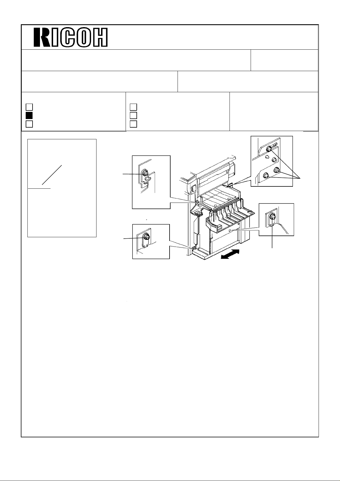
Technical Bulletin No. RTB-008
REVISED ON JUNE 15
SUBJECT: Bending Finsher Top Cover DATE: Mar. 31,’91
PAGE: 1 of 2
PREPARED BY: M. Ninomiya
CHECKED BY:
CLASSIFICATION:
Action Required
Troubleshooting
Retrofit Information
1. Phenomenon
The finisher top cover [A] is bent and it makes a noise when it is opened or closed.
Normal
Revision of service manual
Information only
Other
FROM: Copier Technical Support Sec.
MODEL: F40 Finisher
2. Cause
The rear top cover [B] and/or front top cover [C] of the finisher has not been installed
correctly. It does not fit over part of the finisher frame [D]. As a result, the side(s) of the
finisher’s top cover cannot close completely. The cover also makes a noise as it is being
opened/closed.
[B]
Bent
[D]
[D]
[A]
[C]
[C]
[D]
Page 28

Technical Bulletin No. RTB-008
SUBJECT: Improper Stapling DATE: Mar 31,1991
PAGE: 2 of 2
3. Solution (From April production)
The finisher frame [A] has been redesigned. For the new frame, we eliminated the shaded
area [B], making it easier to reinstall the finisher’s front and rear top covers.
[B]
[A]
3. Action (For before April production)
With a screwdriver, loosen the two screws securing the front and/or rear top cover [C].
Then, use a small flat head screwdriver as shown to pry out the edge of the cover [C] so
that it fits over the edge [D] of the frame. Tighten the screws.
[C]
[C]
[D]
[D]
[C]
[C]
[C]
[C]
Incorrect
[D]
Correct
[D]
Incorrect
Correct
Page 29

Technical Bulletin No. RTB-009
SUBJECT: Installation Procedure change DATE: May 31,1991
PAGE: 1 of 1
PREPARED BY: F. Noguchi
CHECKED BY: T. Ito
CLASSIFICATION:
Action Required
Troubleshooting
Retrofit Information
Since the location of shipping tape on the cassette bank section has been changed and a
cushion has been added, the procedure has been changed as follows:
OLD
Revision of service manual
Information only
Other
FROM: Copier Technical Support Section
MODEL:
F 40
[C]
[B]
6. Slide out the paper feed unit [B], then remove all strips of filament tape [C].
NEW
[C]
[D]
[B]
6. Slide out the paper feed unit [B], then remove all strips of filament tape [C] and the
cushion [D].
This modification is applied from the 1991 May production run.
Page 30

Technical Bulletin No. RTB-010
SUBJECT: Sorter installation procedure correction for the F40. DATE: Jun.15,’91
PAGE: 1 of 2
PREPARED BY: M. Ninomiya
CHECKED BY:
CLASSIFICATION:
Action Required
Troubleshooting
Retrofit Information
1) Installation procedure correction in the service manual.
Two steps [A] were inserted on page 8-14, between steps 12 and 13 of the current F40
service manual.
Revision of service manual
Information only
Other
FROM: Copier Technical Support Sec.
MODEL: F40
[A]
13. Peel off the cover [C] from the Sort/Staple key panel (left side of the operation
panel).
14. Remove the Staple Position key top [D], and affix the Sort/Stack key cover [E]
(copier accessory) as shown.
Page 31

Technical Bulletin No. RTB-010
SUBJECT: Sorter installation procedure correction for the F40 DATE: Jun. 15, ’91
PAGE: 2 of 2
2) Installation procedure correction for the booklet in the machine container.
Illustration [A] was added, and steps [B] were inserted between installation procedure
steps 8 and 9.
[A]
[B]
9. Peel off the cover [C] from the Sort/Staple key panel (left side of the operation panel).
10. Remove the Staple Position key top [D], and affix the Sort/Stack key cover [E]
(copier accessory) as shown.
11.Set SP71-1 to enable the sorter. (Refer to the copier installation procedure.)
NOTE: Corrected installation procedure will be enclosed from August ’91 production.
Page 32

Technical Bulletin No. RTB-011
SUBJECT: Original side to side registration DATE: 15 Aug. ’91
PAGE: 1 of 5
PREPARED BY: J. Kasamoto
CHECKED BY:
CLASSIFICATION:
Action Required
Troubleshooting
Retrofit Information
1. Replacement of the original table and side fences for machines produced before
June ’91.
Replacement procedure
1. Remove the RDH front [A] and rear [B]
covers (5 and 5 screws).
2. Open the left cover [C] by pushing the
release lever button.
3. Remove the feed-in unit top cover [D] (4
screws).
4. Remove the original stopper solenoid [E]
with the bracket on (1 screw), but do not
let the solenoid hang down by the
harness.
Revision of service manual
Information only
Other
FROM: Copier Technical Support Section
MODEL:
F40 (RDH)
[D]
[C]
[A]
[F]
[E]
[B]
5. Remove the release lever unit [F] (2
screws and 2 springs). The springs may
suddenly release so be careful not to lose
the springs.
6. Remove the original stopper unit this way
(1 screw and 1 stud);
As in figure 2, first remove the front side
screw, then loosen the stopper pin [G].
After loosening the rear stud screw, lift up
the front side of the original stopper unit
[H] and unsecure the stud screw [I].
Remove the tension spring from the
spring anchor.
7. Remove the original entrance guide
assembly [J] (4 screws), and be careful
not to damage the harness and the
mylars.
Fig. 1
[G]
[H]
[J]
[I]
Fig. 2
Page 33

Technical Bulletin No. RTB-011
SUBJECT: Original side to side registration DATE: 15 Aug. ’91
PAGE: 2 of 5
8. Remove the original table with the side
fences (7 screws) as in figure 3.
Make sure that the feed-out unit is placed
at the right end [A].
Be careful not to damage the exit roller
paper guard [B].
9. Remove all the parts from the original
table.
10. Place the side fence in the middle of the
new original table [C], and assemble the
new table unit as shown in figure 4. The
parts marked [*] are new parts. Refer to
Modification Bulletin (F40 - No. 11)
[B]
[A]
11. Reinstall the unit.
NOTE: When reinstalling the unit, make
sure of the following.
• Set the new original table following the
sequence in figure 3, but in reverse.
[*]
Fig. 3
[*]
[*]
[C]
[*]
[*]
Fig. 4
Page 34

Technical Bulletin No. RTB-011
SUBJECT: Original side to side registration DATE: 15 Aug. ’91
PAGE: 3 of 5
• Reinstall the springs for the release lever
unit as in figure 5.
Fig. 5
• When reinstalling the original stopper
solenoid, make sure that the harness is
out of the way [A] and that you place the
bracket in the socket [B] as shown in
figure 6.
[A]
• Check to see if the release lever and the
original stopper unit work properly.
• Make sure the three original stoppers are
parallel and that the stoppers do not
touch the original table unit. The
specifications are shown in figure 7.
• Test run the machine before
reassembling the front and rear covers.
[B]
Fig. 6
Fig. 7
1 ± 0.2 mm
Page 35

Technical Bulletin No. RTB-011
SUBJECT: Original side to side registration DATE: 15 Aug. ’91
PAGE: 4 of 5
2. Adjustment
-- Preparation (making a test sheet) --
1. Fold an A4 (81/2 x 11) sheet exactly in half. Then draw a 2.5 cm (1 inch) line [A] on the
crease from the edge of the sheet.
-- Confirmation --
1. Put the test sheet directly on the exposure glass and make a copy (platen mode).
2. Check to see if the copier side to side registration is adjusted properly.
3. Feed the original in the RDH so that the edge with the line faces away from the original
feed rollers.
4. Compare the copy with the test sheet.
[A]
2.5 cm
Test sheet RDH case 1 RDH case 2 RDH case 3
Case 1: Both are identical. Reassemble the copier. No further steps are
needed.
Cases 2 and 3: The copy image has moved. Follow the procedure below.
5. Open the document feeder.
6. Remove the transport belt unit [B] (4
screws) as in figure 8.
[B]
Fig. 8
Page 36

Technical Bulletin No. RTB-011
SUBJECT: Original Side to Side Registration DATE: 15 Aug. ’91
PAGE: 5 of 5
[B]
[C]
[C]
[A]
Fig. 9
7. Loosen four screws [A] on the original table and adjust the side registration as shown
in figure 9. If case 2, follow procedure a. If case 3, follow procedure b.
a) Case 2: The copy image has moved up. Measure the difference and adjust the
tray’s position by pulling it away from the RDH pedestal [B-direction].
Make sure the adjustment matches the difference.
b) Case 3: The RDH copy image has moved down. Measure the difference and
adjust the tray’s position by pushing it towards the RDH pedestal
[C-direction]. Make sure the adjustment matches the difference.
8. Reassemble the document feeder.
9. Repeat the procedure from step 3. (Until both copies are identical.)
[B]
Page 37

Technical Bulletin No. RTB-012
SUBJECT: 1. Additional steps for scanner wire replacement
2. Troubleshooting for SC21
PREPARED BY: J. Kasamoto
CHECKED BY:
CLASSIFICATION:
Action Required
Troubleshooting
Retrofit Information
Additional steps are needed in the service manual’s scanner wire replacement procedure.
Troubleshooting information relating to these steps is explained after.
1. Additional Steps
1-1 First, before reinstalling the wire (service manual P5-14, step 7), make sure of the
following.
• Bring the cushion [A] to the side that has the larger hook.
• The end that has the larger hook and the cushion, will connect to the spring as in
figure 1.
Revision of service manual
Information only
Other
FROM: Copier Technical Support Section
MODEL:
F40
DATE: 15 Aug. ’91
PAGE: 1 of 2
[A]
Fig. 1
1-2 Add these steps to the service manual P5-15, immediately following step 12.
• Loosen the 2 screws on the cushion holder [C]. Pull the holder towards the pulley
as far as it will go ([D]: direction) as in figure 2. Tighten the screws temporarily.
[D]
[B]
Fig. 2
[C]
Page 38

Technical Bulletin No. RTB-012
SUBJECT: 1. Additional steps for scanner wire replacement
2. Troubleshooting for SC21
• Perform a free run for 1 minute (DIP SW 902-1 on). Make sure that the scanners
DATE: 15 Aug. ’91
PAGE: 2 of 2
and wire operate smoothly.
• Loosen the 2 screws on the cushion holder. Position the holder so that the cushion
is tightly fit between the holder and the wire hook ([A]: direction) as in figure 3.
[A]
Fig. 3
• Go to the service manual P5-15, step 13.
2. Troubleshooting
[Symptom]
After making about 1 million copies, SC21 lights and the machine stops.
[Cause]
The wire extends and a space appears between the cushion and the holder (figure 4).
This causes the pulley and the wire to slip. When this phenomenon occurs, the scanner
can not go back to its home position.
Fig. 4
[Action in the field]
• Remove the rear cover (2 screws).
• Remove the fusing cooling fan motor [B] as in figure 1 (2 screws, 1 connector).
• Loosen the 2 screws on the cushion holder and slide it towards the spring.
• Secure the screws. Make sure the cushion is tightly positioned between the hook
and the cushion holder. (Figure 3)
NOTE: After making about 2 million copies, SC21 may light on again. If no further
adjustment is possible with the old cushion holder at that time, refer to MB No.
19 and replace with new cushion holder.
Page 39

Technical Bulletin No. RTB-013
SUBJECT: PM Information - Lubrication Points DATE: Aug. 31 ’91
PAGE: 1 of 5
PREPARED BY: J. Kasamoto
CHECKED BY:
CLASSIFICATION:
Action Required
Troubleshooting
Retrofit Information
This RTB shows all the lubrication points with the illustrations which should be performed
at Preventive Maintenance.
1. Scanner Guide Rods, Plate, and Guide Rod Felts (Cleaners):
PM Interval = 80 K
Lubricant = Launa oil
Guide Rod Plate
Revision of service manual
Information only
Other
FROM: Copier Technical Support Section
MODEL:
F40
Guide Rod Felts (Cleaners)
Guide Rods
Page 40

Technical Bulletin No. RTB-013
SUBJECT: PM Information - Lubrication Points DATE: Aug. 31 ’91
PAGE: 2 of 5
2. Separation Roller Slip Clutch:
(1st, 2nd, 3rd Paper Feed Stations, and Duplex Paper Feed Station)
PM Interval = 80 K
Lubricant = Mobil Temp. 78
3. Paper Lift Motor Worm Gear:
(2nd and 3rd Paper Feed Stations)
PM Interval = 160 K
Lubricant = Mobil Temp. 78
(B)
(A)
Remarks:
Oil holes on the inner hub (A) and inside
the spring (B) should be lubricated.
Page 41

Technical Bulletin No. RTB-013
SUBJECT: PM Information - Lubrication Points DATE: Aug. 31 ’91
PAGE: 3 of 5
4. Paper Feed Gears:
PM Interval = 160 K
Lubricant = Mobil Temp. 78
5. Development Unit Drive Gears:
PM Interval = 80 K
Lubricant = Silicon Grease G40M
6. Fusing Roller Drive Gears:
PM Interval = 160 K
Lubricant = Mobil Temp. 78
(A)
Remarks:
Lubricate only the top of the Gear.
Do not lubricate inside the coupling
gear (A).
Page 42

Technical Bulletin No. RTB-013
SUBJECT: PM Information - Lubrication Points DATE: Aug. 31 ’91
PAGE: 4 of 5
7. Registration Roller Gears:
PM Interval = 160 K
Lubricant = Mobil Temp. 78
8. Relay Roller Gears:
(1st, 2nd and 3rd Relay Rollers)
PM Interval = 160 K
Lubricant = Mobil Temp. 78
Page 43

Technical Bulletin No. RTB-013
SUBJECT: PM Information - Lubrication Points DATE: Aug. 31 ’91
PAGE: 5 of 5
9. Exit Rollers Drive Gears:
PM Interval = 160 K
Lubricant = Mobil Temp. 78
Page 44

Technical Bulletin No. RTB-014
SUBJECT: RDH - Original misfeed
(Original stopper solenoid lever breakage)
PREPARED BY: N. Takai
TO: Copier Technical Support Section
DATE: Dec. 31, ’91
PAGE: 1 of 1
CHECKED BY:
CLASSIFICATION:
Action Required
Troubleshooting
Retrofit Information
Revision of service manual
Information only
Other
MODEL: F40 RDH
(Phenomenon)
The original misfeed indicator lights because the stack of originals cannot be fed into the
RDH feed-in position, even after the start key is pressed.
As reported from the field (the occurrence ratio is low), it happens about 100 ∼ 200 k
copies after the machine installation. And, the earliest one appeared after about 50 k
copies.
(Cause)
The original stopper solenoid lever which does not have sufficient durability breaks due to
material fatigue. Then, the original stopper gate cannot open.
Original Stopper
Lever
Solenoid
Stress may be concentrated
to this portion
(Action required)
Replace the stopper solenoid lever with a new one.
To increase durability, the material and shape of the solenoid lever was modified as
follows:
(P/N A4991332) (P/N A4991332A)
(old type) (new type)
NOTE: - This modification has been implemented from ’91 November production onward.
- The new part is now available at our parts center.
Page 45

Technical Bulletin No. RTB-015
SUBJECT: Blinking Wrench Mark DATE: Feb. 15, ’92
PAGE: 1 of 2
PREPARED BY: S. Tomoe
CHECKED BY:
CLASSIFICATION:
Action Required
Troubleshooting
Retrofit Information
Symptom:
The wrench mark is blinking.
Possible Cause:
1. The following connector pins for the main board have been disconnected.
• CN102--A1 • CN102--B1
• CN102--A8 • CN101--A3
2. The ID sensor board and the connector for the ID sensor are in poor contact because
the position of the connector for the ID sensor does not match the one for the ID
sensor board.
Revision of service manual
Information only
Other
FROM: Copier Technical Support Section
MODEL: F40
Action Required:
1. Make sure that you reconnect the following connector pins:
• CN102--A1 • CN102--B1
• CN102--A8 • CN101--A3
Blue
e.g.
CN102--B1
Page 46

Technical Bulletin No. RTB-015
SUBJECT: Blinking Wrench Mark DATE: Feb. 15, ’92
PAGE: 2 of 2
2. (1) Remove the ID sensor board.
(2) Clean the connector of the ID sensor board (both faces) using a soft cloth with
alcohol.
(3) Reassemble the ID sensor board.
(4) Remove the upper rear cover.
(5) Loosen the screw of the ID sensor connector bracket [A] then tighten the screw
while pushing down the bracket.
CAUTION: Make sure that you do not turn the bracket when tightening the screw.
[A]
(6) Check the value of Vsg and Vsp using SP55 (the value of Vsg should be around 4.0
V)
Page 47

Technica l Bulletin No . RTB-01 7
SUBJ ECT: Ori gin al m isfe ed . DATE:
Mar. 15, 1993
PAGE: 1 o f 2
PREPARED BY: N . Tak ai
CHECKED BY:
CLASSIFICATION:
Action Required
Troubleshooting
Retrofit Information
Revision of service manual
Information only
Other
FROM: Copier Technical Support Section
MODEL:
F40 ARDF
Symptom:
Original misfeed occ urs intermittently.
Possible Ca use:
1. The DF registration sensor is activated by paper dust on the sensor pad, affecting its
color.
2. When t he o rig inal feed ro ller star ts r ot ating , t he DF up pe r g uid e plat e is war ped slig ht ly
downward. The clearance between the DF registration sensor and the sensor pad is
reduced. When this happens, the DF registration sensor (reflective type) can receive the
reflective light from the sensor pad, even though its color is black.
Action Required:
(For cause 1)
1. Op en th e feed -in un it [A] .
2. Clean t he DF regist ratio n s enso r
surface [B] and the sensor pad [C].
NOTE: To remove the paper dust from
the sensor pad, it is better to
use scotch tape.
[B]
[C]
[A]
Page 48

Technica l Bulletin No . RTB-01 7
SUBJ ECT: Ori gin al m isfe ed . DATE:
Mar. 15, 1993
PAGE: 2 o f 2
(For cause 2)
1. Remove the two screws of the pull out
hinge [D].
2. Ins ert 2 pc s eac h of 0. 8 mm sp ac er
(P/No . 07010040) and fix th e sc rew s.
[E].
•
This c an g ive the reg ist ratio n s enso r
enough clearance for the sensor pad.
[E]
[D]
Perma nent Counterme asure :
The shap e of t he pu ll ou t br ack et (P/N o. A4651057) will be mo d ified so that the sen sor
pad is positioned 1.5 mm further from the DF registration sensor.
Soon after the modification is applied to the produc tion, an M/B will be issued.
Page 49

Technical Bulletin No. RTB-018
SUBJECT: No Display DATE: Mar. 15, ’94
PAGE: 1 of 1
PREPARED BY: S.MANO
CHECKED BY: S. Hamano
CLASSIFICATION:
Action Required
Troubleshooting
Retrofit Information
If the transistor "Q7" on the PCC power pack becomes defective due to heating, the
following phenomenon occurs:
The operation panel indicates nothing. This is because the FU3 (fuse for 24V dc line) on
the DC power supply board is blown. This is caused by excessive current due to defective
transistor "Q7" on the PCC power pack.
Under this condition, if the FU3 is replaced without replacing the PCC power pack, the
FU3 may be blown again.
To improve the durability of the PCC power pack, a heat sink has been added to transistor
"Q7" on the PCC power pack.
Revision of service manual
Information only
Other
FROM: 2nd Technical Support Section
MODEL: F40
This improvement is implemented to the mass-production machines from the following
serial number.
Japan production REI production
A053-19 272 3100 001~ A053 -15 583 4700 001~
A053-22 230 3110 101~ A053 -17 272 3470 204~
A053-25 230 3100 001~
A053-26 3A01130001~
A053-27 272 3100 026~
A053-29 272 3100 076~
The part number of the PCC power pack is the same after the modification. (The suffix of
the improved power pack is "A").
 Loading...