

Page 1
Technical Bulletin
No.
RTB-001
SUBJECT: Dirty Background on Color Copies
PREPARED BY: .
CHECKED BY:
CLASSIFICATlON:
■ Action Required
❑ Troubleshooting
Phenomenon ]
[
Cause ]
[
Countermeasure ]
[
Itoh
.
❑ Revision of service manual
❑ Information only
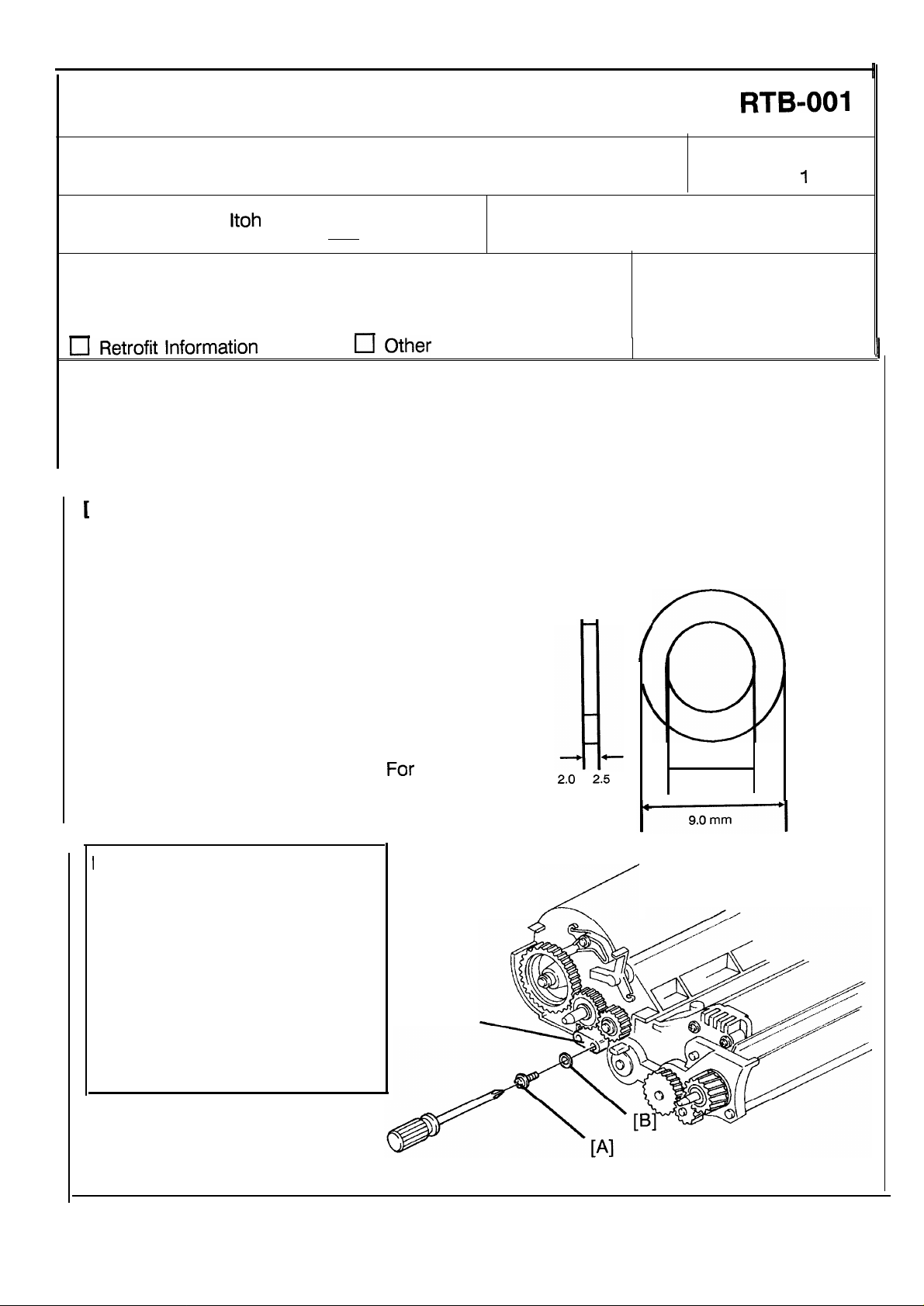
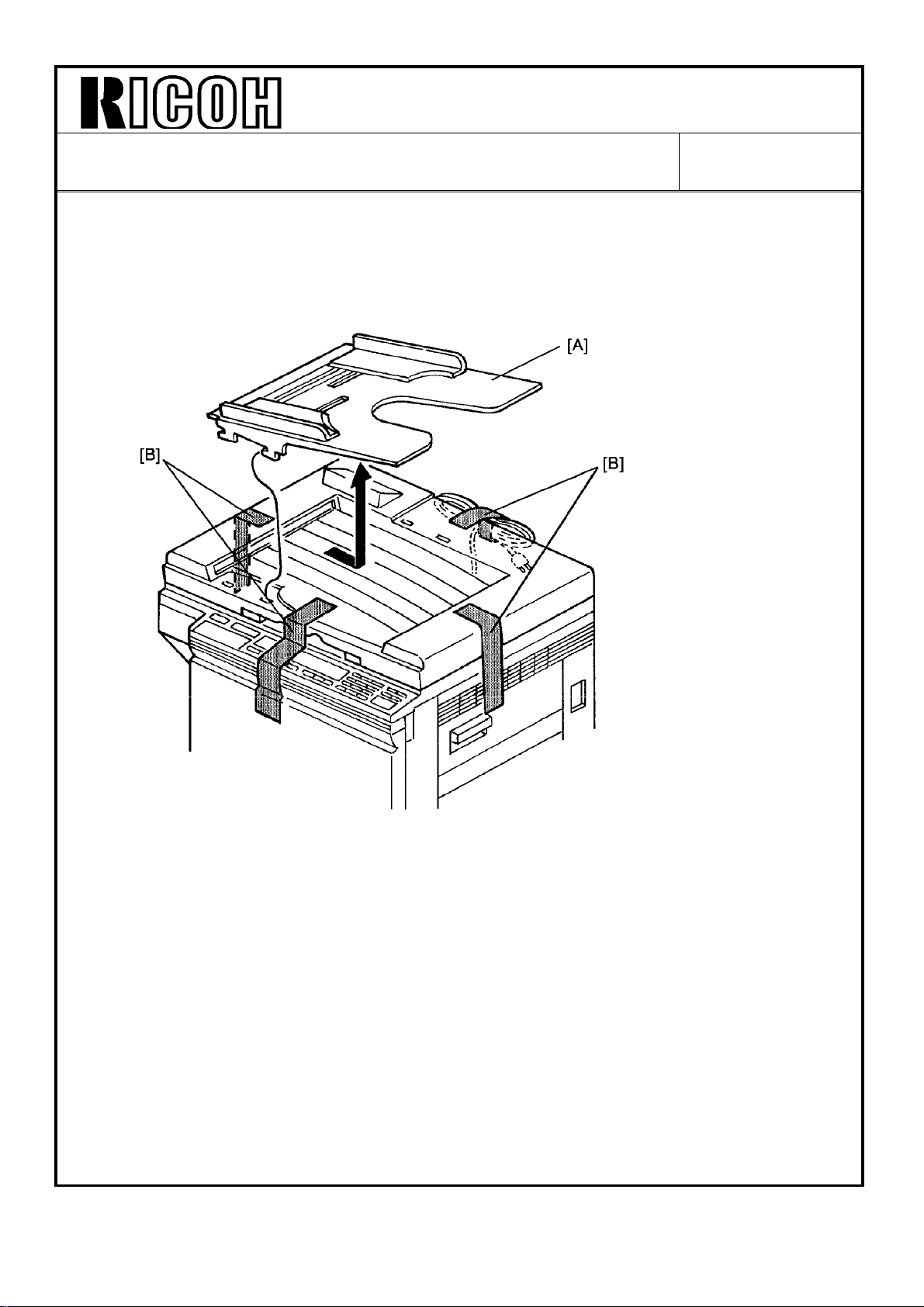
Color copies have a dirty background
The screw [A] at the rear side of the color development unit does
not extend for enough to push in the color switch. Consequently,
black toner density control is selected and toner density becomes
high. This causes a dirty background.
If the problem occurs or when installing a color development unit,
install a spacer [B] as shown in the following illustration. This
spacer must be 2.0 to 2.5 mm thick and the outside diameter must
be less than 9.0 mm. Then, check whether the color indicator
properlv Iights when the color development unit is installed on the
rnachine.
-
DATE:
PAGE: 1 of
FROM: Copier Technical Support Group
MODEL: N220
.
Oct.
4, ’90
1
!
NOTE1: If a spacer thicker than 2.5 mm is
used, the screw on the
development unit may damage
the color switch.
NOTE2: A 2.0 mm width spacer will be
added as an accessory to the
For
color development unit.
cut-in serial number, please refer
to the modification bulletin that we
will be issuing soon.
the
NOTE:
If you have no spacer that meets
the above specifications, adjust
the position of the screw [A] as
follows:
While inserting a 2.0 mm thickness gauge between the screw
and part [C], tighten the screw
.
[A]
[c]
2,0
to 2.5
4.0 mm
Page 2
Technical Bulletin
No.
RTB-002
SUBJECT: Service Manual Correction (Water Proof)
PREPARED
CHECKED BY:
CLASSIFICATlON:
❑ Action Required
❑ Troubleshooting
❑ Retrofit Information
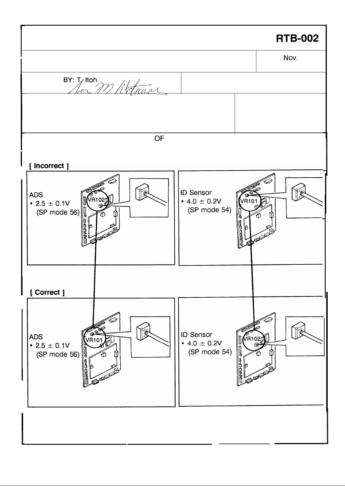
There are some mistakes in the “TABLE
The illustrations for ADS and ID
Please correct your manual as shown below:
l---
■ Revision of service manual
❑ Information only
❑ Other
sensors adjustments are incorrect.
L.
OF
ADJUSTMENTS” section of the waterproof.
DATE:
PAGE: 1 of 1
FROM: Copier Technical Support Sec.
MODEL: N220
NOV. 30, ’90
Page 3
Technical Bulletin
No. RTB-003
SUBJECT: C/G/B Power Pack Damage
PREPARED B
CHECKED B
CLASSIFICATI
❑ Action Req
Troubleshooting
❑ Retrofit Information
-—.
[ Phenomenon ]
[ Cause
[ Countermeasure
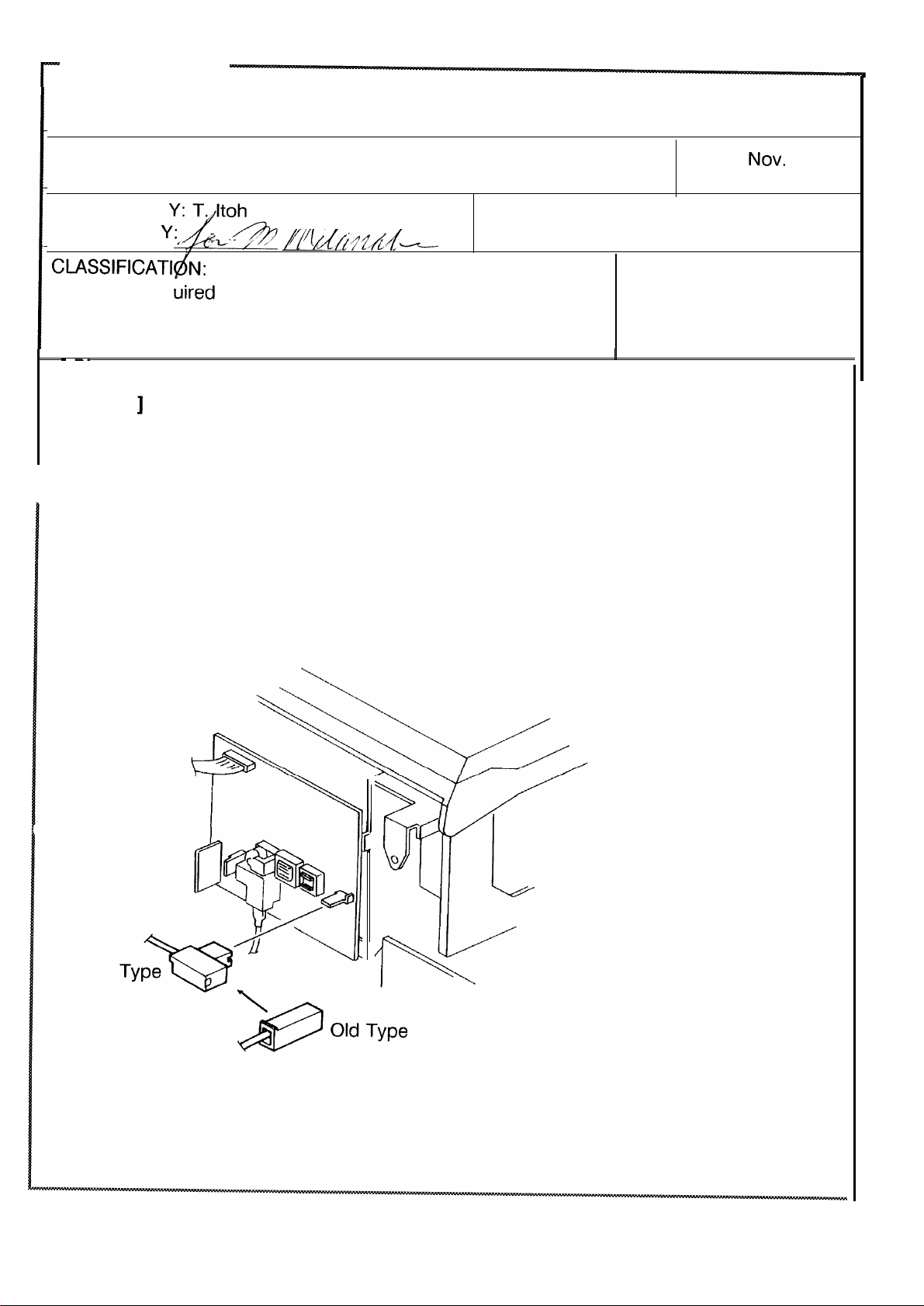
On the production
The clearance between the bias harness connector and the rear cover is increased by
changing the shape of the connector as shown below: This prevents the connector from
being pressed by the rear cover.
]
Dirty background may occur.
The bias connector on the C/G/B power pack may be pressed
against the power pack’s PCB by the rear cover. This damages
the PCB. As a result, incorrect bias voltage is applied to the
development roller and dirty background occurs.
]
line
❑ Revision of service manual
❑ Information only
❑ Other
FROM: Copier Technical Support Sec.
MODEL: N220
I
DATE:
PAGE: 1 of 3
NOV.
30, ‘90
New
This modification has been implemented on the production units from the October
mass-production run.
Page 4
Technical Bulletin
No.
RTB-003
SUBJECT: C/G/B Power Pack Damage
In the field
New Type
Bias Connector
To prevent this from occurring, bend the bias terminal as
explained below to make clearance between the rear cover and
the bias terminal. Do this at installation or during the next
maintenance call.
[A]
DATE:
PAGE: 2 of 3
NOV. 30, ‘90
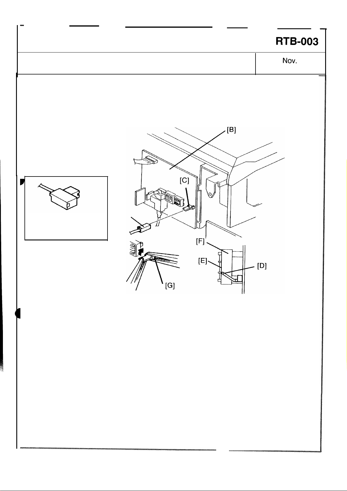
NOTE: It is not necessary to perform the following procedure on the machine that has a
new type bias connector.
1. Turn off the main switch and unplug the power supply cord.
2. Remove the rear cover (4 screws).
3. Disconnect the bias connector [A] from the C/G/B power pack [B].
4. Bend the bias terminal [C] until the terminal edge [D] is aligned with the line [E] on the
transformer [F] on the power pack while holding the base [G] of the terminal with a pair
of pliers.
NOTE: a. Be careful not to damage the soldered connection between the terminal and the
pattern on the PCB.
b. Do not to far bend the terminal. Otherwise, a poor connection between the
terminal and the connector will result.
5. Reconnect the bias connector and reinstall the rear cover.
. . . . . . . . . . . . . . . . . . . . . . . . . . . . . . . . . .
Page 5
m
Technical Bulletin
SUBJECT: C/G/B Power Pack Damage
New Type
Bias Connector
No.
RTB-003
DATE:
PAGE: 3 of 3
NOV. 30, ’90
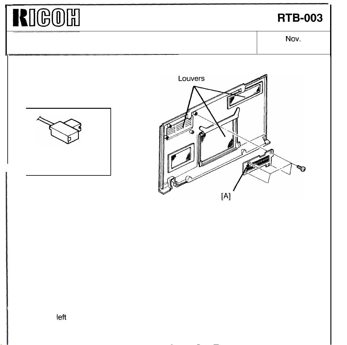
NOTE: Some of the May ’90 production machines have the louver plates on the rear
cover as shown in the illustration.
These louver plates have been removed from the rear cover with the modification.
The cut-in serial number was not checked since this modification had an
interchangeability.
If the louver plates are installed on the rear cover, the left upper-side louver plate
[A] contacts the bias connector (new type) when the rear cover is installed. This
may damage the C/G/B power pack.
left
The
new type bias connector (as shown above) and the rear cover having the louver
plates.
upper-side louver plate must be removed on the machines that have the
Page 6
Technical Bulletin No. RTB-004
SUBJECT: The reason why Vsp remains above 0.5 volts DATE: Dec. 31, ’90
PAGE: 1 of 2
PREPARED BY: T. Itoh
CHECKED BY:
CLASSIFICATION:
Action Required
Troubleshooting
Retrofit Information
The conditions under which Vsp remains above 0.5 volts are as follows:
The amount of toner supplied to the development unit depends on the ratio of Vsg and
Vsp. (Please refer to the following table for the toner supply levels.)
ID Sensor Data
Vsp/Vsg x 100
(Vsp, if Vsg = 4.0 volts)
0 to 12.5%
(0 to 0.5 volts)
12.5 to 15.0%
(0.5 to 0.6 volts)
15.0 to 17.5%
(0.6 to 0.7 volts)
17.5 to 25.0%
(0.7 to 1.0 volts)
25.0 to 62.5%
(1.0 to 2.5 volts)
(See NOTE below.)
62.5 % to 100% or higher
(2.5 to 5.0 volts)
Revision of service manual
Information only
Other
Toner Supply Level
(Toner Supply Ratio, if SP
#31 = 0)
No toner supply
(0%)
1
(3.75%)
2
(7.5%)
3
(15%)
4
(30%)
Fixed Supply Mode N/A
FROM: Copier Technical Support Sec.
MODEL:
N220
ID Sensor Data
0
15
29
59
118
NOTE:
If this condition is detected two times consecutively, the toner supply ratio rises to 60% (ID
Sensor Data = 236), which is double that at toner supply level 4.
The N220 is designed to vary toner supply according to the type of original and to
continuously supply toner to the development unit as long as the total image area on the
original is 3.75% or higher. Continuous toner supply minimizes variation in the toner
density in the development unit.
Page 7

Technical Bulletin No. RTB-004
SUBJECT: The reason why Vsp remains above 0.5 volts DATE:
PAGE: 2 of 2
Example 1:
If SP mode #31 is set to 0 and Vsp is greater than 0.5 volts but less than 0.6 volts, the
main CPU sets the toner supply level to 3.75%. The toner supply level is set to 3.75% and
toner is supplied at every copy cycle when the total image area on the original is greater
than 3.75 % and less than 7.5%.
Example 2:
When copies are made of the OS-A3 chart (24% total image area), the Vsp remains at
slightly higher than 1.0 volt. The toner supply ratio changes to 30% and toner is supplied
at every copy cycle as shown in the above table.
Therefore, Vsp does not drop below 0.5 volts as long as originals have at least 3.75% total
image area.
Page 8
Technical Bulletin No. RTB-005
SUBJECT: Scanner movement DATE: Dec. 31, ’90
PAGE: 1 of 2
PREPARED BY: T. Itoh
CHECKED BY:
CLASSIFICATION:
Action Required
Troubleshooting
Retrofit Information
[ Phenomenon ]
When the Start key is pressed, the scanner does not start smoothly from the home
position, causing vibration noise.
[ Cause ]
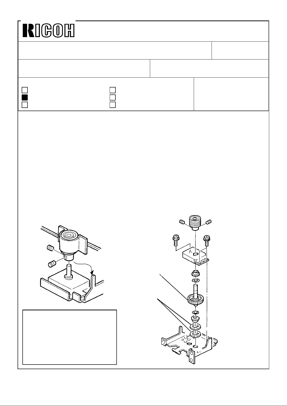
Two sponge spacers [A] are located in the scanner motor assembly as shown in the
illustration. The sponge spacers may interfere with the rotation of the scanner drive gear
[B].
[ Countermeasure ]
Revision of service manual
Information only
Other
FROM: Copier Technical Support Sec.
MODEL:
N220
Remove one of the sponge spacers from the scanner motor assembly. (It does not matter
which spacer is removed.)
[B]
[A]
NOTE:
To prevent the scanner wires
come off the pulley when removing the sponge spacer, set the
omega clamp on the pully. Then,
remove the pulley and place it on
the bracket as shown.
Page 9
Technical Bulletin No. RTB-005
SUBJECT: Scanner movement DATE: Dec. 31, ’90
PAGE: 2 of 2
Removal of the sponge spacer is being done on the production line. The machines which
have two sponge spacers are as follows:
Model Code
A048-15 July production units - September production
units
A048-16 & 25 ---A048-17 July production units - 2590100478
A048-19 July production units - September production
units
A048-26 July production units - September production
units
A048-27 July production units - October production units
A048-28 ---A048-29 July production units - October production units
Page 10
Technical Bulletin No. RTB-006
SUBJECT: Service Manual Correction DATE: Feb. 15, ’91
PAGE: 1 of 9
PREPARED BY: T. Itoh
CHECKED BY:
CLASSIFICATION:
Action Required
Troubleshooting
Retrofit Information
Some mistakes were found in the manual. Please correct your manual as follows:
1. Page 1-2
Incorrect Correct
Power Source:
110V/60Hz/15A
115V/60Hz/15A
220V/50Hz/ 8A
220V/60Hz/ 8A
240V/50Hz/ 8A
(The correction is bolded.)
Revision of service manual
Information only
Other
FROM: Copier Technical Support Sec.
MODEL: N220
Power Source:
110V/60Hz/15A (for Taiwan)
115V/60Hz/15A (for N.A.)
220V/50Hz/ 8A (for EU.)
220V/60Hz/ 8A (for EU.)
240V/50Hz/ 8A (for EU.)
2. Page 1-3
Incorrect Correct
Section A: See page 7.
Section B: See page 8.
Section C: See page 10.
3. Page 2-23
Incorrect Correct
SE: Side erase margin
2.0 ± 1.0 mm on each side;
4. Page 2-24
Remove the following contents from the manual:
"The side erase margin overlaps the edges of the paper to prevent edge lines from
appearing on the copy."
(The correction is bolded.)
Section A: See page 1-4.
Section B: See page 1-5 or 1-6.
Section C: See page 1-7 or 1-8.
(The correction is bolded.)
SE: Side erase margin
2.0 ± 2.0 mm on each side;
Page 11
Technical Bulletin No. RTB-006
SUBJECT: Service Manual Correction DATE: Feb. 15, ’91
PAGE: 2 of 9
5. Page 2-25
(Incorrect)
Blocks On Paper Size Reproduction Ratio (%)
None
a
a - b
a - c
a - d
a - e
a - f
a - f, g
All
(Correct)
Blocks On Paper Size Reproduction Ratio (%)
None
a
a - b
a - c
a - d
a - e
a - f
a - f, g
All
A3, A4 side ways
11"x17", 11"x8 1/2
B4
8 1/2"x11", 8 1/2"x5 1/2"
A4 lengthwise
B5 lengthwise
A5 lengthwise, 5 1/2"x8 1/2"
A3, A4 side ways
11"x17", 11"x8 1/2
B4
8 1/2"x11", 8 1/2"x5 1/2"
A4 lengthwise
B5 lengthwise
A5 lengthwise, 5 1/2"x8 1/2"
99 - 200
96 - 98
86 - 95
For ID sensor pattern
For Vr Correction
98 - 200
92 - 97
86 - 91
80 - 85
71 - 79
61- 70
50 - 60
For ID sensor pattern
For Vr Correction
6. Page 2-43
(Incorrect)
ID Sensor Data
Vsp/Vsg x 100
(Vsp, if Vsg = 4.0 volts)
0 to 12.5%
(0 to 0.5 volts)
12.5 to 15.0%
(0.5 to 0.6 volts)
15.0 to 17.5%
(0.6 to 0.7 volts)
17.5 to 62.5%
(0.7 to 1.0 volts)
62.5 % to 100% or higher
(2.5 to 5.0 volts)
Toner Supply Level
(Toner Supply Ratio, if SP #31
= 0)
No toner supply 0
1 15
2 29
3 59
Fixed Supply Mode N/A
ID Sensor Data
Page 12
Technical Bulletin No. RTB-006
SUBJECT: Service Manual Correction DATE: Feb. 15, ’91
PAGE: 3 of 9
(Correct)
ID Sensor Data
Vsp/Vsg x 100
(Vsp, if Vsg = 4.0 volts)
0 to 12.5%
(0 to 0.5 volts)
12.5 to 15.0%
(0.5 to 0.6 volts)
15.0 to 17.5%
(0.6 to 0.7 volts)
17.5 to 25.0%
(0.7 to 1.0 volts)
25.0 to 62.5%
(1.0 to 2.5 volts)
(See NOTE below.)
62.5 % to 100% or higher
(2.5 to 5.0 volts)
Toner Supply Level
(Toner Supply Ratio, if SP #31
= 0)
No toner supply
(0%)
1
(3.75%)
2
(7.5%)
3
(15%)
4
(30%)
Fixed Supply Mode N/A
ID Sensor Data
0
15
29
59
118
NOTE: If this condition is detected two times consecutively, the toner supply ratio
rises to 60% (ID Sensor Data = 236), which is double that at toner supply
level 4.
7. Page 2-63
(Incorrect)
(The correction is bolded.)
Paper Size Switch Size Indication
4 5 6 7
11" x 8 1/2" 1 1 1 0 11" x 8 1/2"
(Correct)
Paper Size Switch Size Indication
4 5 6 7
11" x 8 1/2" 1 1 1 0 8 1/2" x 11"
8. Page 2-65
(The correction is bolded.)
Incorrect Correct
The second feed clutch is energized for
150 milliseconds to transfer drive to the
2nd feed roller shaft and turns the 2nd
feed rollers [H].
The second feed clutch is energized for
500 milliseconds to transfer drive to the
2nd feed roller shaft and turns the 2nd
feed rollers [H].
Page 13
Technical Bulletin No. RTB-006
SUBJECT: Service Manual Correction DATE: Feb. 15, ’91
PAGE: 4 of 9
9. Page 2-69
Incorrect Correct
Relay Roller Clutch
150 m sec 150 m sec150 m sec
10. Page 3-3
Incorrect Correct
1. Input Voltage Level:
110V/60Hz/15A:More Than 15A
115V/60Hz/15A:More Than 15A
220V/50Hz/ 8A:More Than 8A
220V/60Hz/ 8A:More Than 8A
240V/50Hz/ 8A:More Than 8A
Relay Roller Clutch
500 m sec 500 m sec500 m sec
(The correction is bolded.)
1. Input Voltage Level:
110V/60Hz/15A:More Than 15A
(for Taiwan)
115V/60Hz/15A:More Than 15A
(for N.A.)
220V/50Hz/ 8A:More Than 8A (for EU.)
220V/60Hz/ 8A:More Than 8A (for EU.)
240V/50Hz/ 8A:More Than 8A (for EU.)
Remove the following contents from the manual:
3. Permissible extension cord : At least 300V, 30A capacity and less than 5 meters
(16.4 ft) long.
11. Page 4-3
Incorrect Correct
When the DF is used with this copier,
DIP switch 101-4 must be turned off to
increase the data transmission speed.
12. Page 4-9
Incorrect Correct
3. Select Service program SP-97 and
press the "1" key on the key pad,
then press the Enter key.
(The correction is bolded.)
When the DF is used with this copier,
DIP switch 101-2 must be turned off to
increase the data transmission speed.
(The correction is bolded.)
3. Select Service program SP-98 and
press the "1" key on the key pad,
then press the Enter key.
Page 14
Technical Bulletin
No.
RTB-006
SUBJECT: Service Manual Correction
13. Page 4-10
Incorrect
SP Modes #5, #6, #11, #37, #42,
#43, #44, #47, #48, #52, #55
#59
14. Page 4-12
Incorrect
The factory setting of SP
in the Service Program Mode Table.
15. Page 4-16
Incorrect
Mode No.
Bias Voltage
*59
Check (Black)
(The correction is
and
j
(The correction is
mode 21 is
(The correction is
“0”
DATE: Feb. 15, ’91
PAGE: 5 of 9
bolded.)
Correct
SP Modes #5, #6, #8, #37,
#42, #43,
#44, #47, #48, #52, #55, and #59
bolded.)
Correct
The factory setting of SP mode 21 is “1”
in the Service Program Mode Table.
bolded.)
Correct
Mode No.
*59
Bias Voltage
Check
16. Page 4-18
Incorrect
The factory setting of SP mode
in the Service Program Mode Table.
17. Page 4-23
Incorrect
(
Output No. 2
(
Charge Corona + Standard Grid
[
Output No. 3
(
Charge Corona + ID Sensor Grid
(
Output No. 4
(
Charge Corona + Vrp Grid
(The correction is bolded.)
(The correction is
76 is “0”
Correct
The factory setting of SP mode 76 is “1”
in the Service Program Mode Table.
bolded.)
Correct
Output No. 2
Charge Corona + Standard Grid
(Grid Voltage = -920 volts)
Output No. 3
Charge Corona + ID Sensor Grid
(Grid Voltage =
-660 volts + Vp
Correction Factor)
Output No. 4
Charge Corona + Vrp Grid
(Grid Voltage = -500 volts)
Page 15
Technical Bulletin No. RTB-006
SUBJECT: Service Manual Correction DATE: Feb. 15, ’91
PAGE: 6 of 9
18 Page 4-24
Incorrect Correct
Out Put No. 60 - 67
Applies grid voltage in 60V steps
starting at 640V
19. Page 4-32
Incorrect Correct
a) ADS Voltage (SP NO. 56)
......2.5 + 0.1V
b) Vsg (SP No. 54)
.....4.0 + 0.2V
20. Page 4-35
Incorrect Correct
2. If the RAM on the main board is still
usable, remove it and place it on the
new main board. Then, install the
new main board.
3. After placing a new RAM on the new
main board, clear the RAM memory
using SP mode #99 (Do not clear
RAM memory if you have placed the
old RAM on the new main board.)
Then check and adjust the data of
the following SP modes:
(The correction is bolded.)
(The correction is bolded.)
Out Put No. 60 - 67
Applies grid voltage in 60V steps
starting at 560V
a) ADS Voltage (SP NO. 56)
......2.5 ± 0.1V
b) Vsg (SP No. 54)
.....4.0 ± 0.2V
2. If the RAM on the main board is still
usable, remove and place it on the
new main board. Then, install the
new main board to the copier.
3. After installing the new main board
with the new RAM, clear the RAM
memory using SP mode #99 (Do not
clear RAM memory if you have
placed the old RAM on the new main
board.) Then check and adjust the
data of the following SP modes:
Page 16
Technical Bulletin No. RTB-006
SUBJECT: Service Manual Correction DATE: Feb. 15, ’91
PAGE: 7 of 9
21. Page 4-37
Incorrect Correct
SP Mode
Numbers
22. Page 5-15
3. Put the bead of the silver wire [2] ion
slot [B] on the Allen screw side.
23. Page 5-28
1. Take out the development roller. 1. Take out the development unit.
12, 20-35, 41-44, 47,
48, 54, 56, 70, 71, 74
Incorrect Correct
Incorrect Correct
(The correction is bolded.)
SP Mode
Numbers
(The correction is bolded.)
3. Put the bead of the silver wire [2] in
slot [B] on the Allen screw side.
(The correction is bolded.)
12, 30-35, 41-44, 47,
48, 54, 56, 70, 71, 74
24. Page 5-67
Incorrect Correct
1. Make the gap between the edge of
the bracket [B] and the entrance
guide plate 3.0 mm as shown in the
illustration. Then, tighten both the
front rear screws.
ADJUSTMENT STANDARD:
GAP "X" Front 2.65 ± 0.1 mm
Rear 3.25 ± 0.1 mm
1. Set the Gap "X" between the edge of
the bracket [B] and the entrance
guide plate adjustment standard
using the thickness gauge as shown
in the illustration. Then, tighten both
the front rear screws.
Page 17
Technical Bulletin No. RTB-006
SUBJECT: Service Manual Correction DATE: Feb. 15, ’91
PAGE: 8 of 9
25. Page 5-73
Incorrect Correct
6. Remove the drum knob [A] and the
bearing [B] from the drum, then
install them on the drum shaft [C]
(special tool : P/N #A0069500).
26. Page 6-43
Incorrect Correct
- Possible Causes -
• Thermistor Open
27. Page 8-6
Incorrect Correct
When the Start key is pressed, the
copier CPU moves the scanner 100
mm away from the left scale and
sends the feed-in signal to the DF.
(The correction is bolded.)
(The correction is bolded.)
(The correction is bolded.)
6. Remove the drum knob [A] and the
bearing [B] from the drum, then
install them on the drum shaft [C]
(special tool : P/N #A0069105).
- Possible Causes -
• Thermofuse Open
When the Start key is pressed, the
copier CPU sends the feed-in signal to
the DF.
28. Page 8-11
The illustration on this page is incorrect. The correct illustration is as follows:
Page 18
Technical Bulletin No. RTB-006
SUBJECT: Service Manual Correction DATE: Feb. 15, ’91
PAGE: 9 of 9
28. Page 8-31
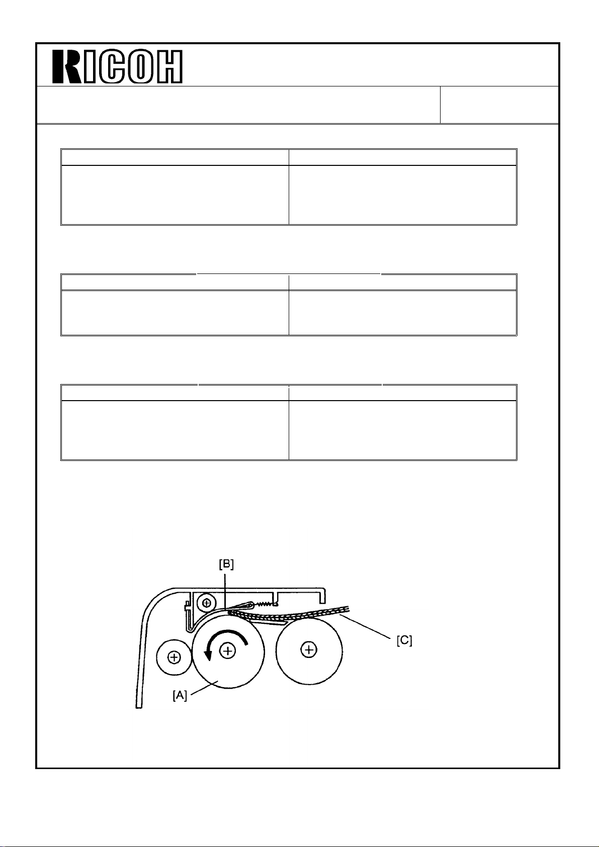
The illustration on this page is incorrect. The correct illustration is as follows:
Page 19
Technical Bulletin No. RTB-007
SUBJECT: Warning Description DATE: Mar. 31, ’91
PAGE: 1 of 1
PREPARED BY: T. Itoh
CHECKED BY:
CLASSIFICATION:
Action Required
Troubleshooting
Retrofit Information
The following warning description is missing from the service manual. The warning
description must be described in the service manual for Safety Standard.
Please add the following warning description to your service manual (Service Remarks
Section).
WARNING: The RAM board has a lithium battery which can explode if handled
incorrectly, replace only with same RAM board. Do not recharge, disassemble or burn
this battery. Used RAM boards must be handled in accordance with local regulations.
Revision of service manual
Information only
Other
FROM: Copier Technical Support Sec.
MODEL: N220
Page 20
Technical Bulletin No. RTB-008
SUBJECT: SP Modes #45 and #46 (Paper Buckle Adjustment) DATE: Mar. 31, ’91
PAGE: 1 of 3
PREPARED BY: T. Itoh
CHECKED BY:
CLASSIFICATION:
Action Required
Troubleshooting
Retrofit Information
The new SP modes (#45 and #46) have been applied to the main ROM (See last page for
cut-in serial numbers.)
SP modes #45 and #46 are to adjust the amount of the paper buckle in the registration
area. The amount of paper buckle can be adjusted by changing OFF timing of the 1st
paper feed clutch or relay roller clutch solenoid.
SP mode #45 is for the 1st feed station and SP mode #46 is for the 2nd feed station.
(Refer to the Table on next page.)
• The reasons for applying these SP modes are as follows:
1. To get the proper amount of paper buckle for various paper, these SP modes were
applied.
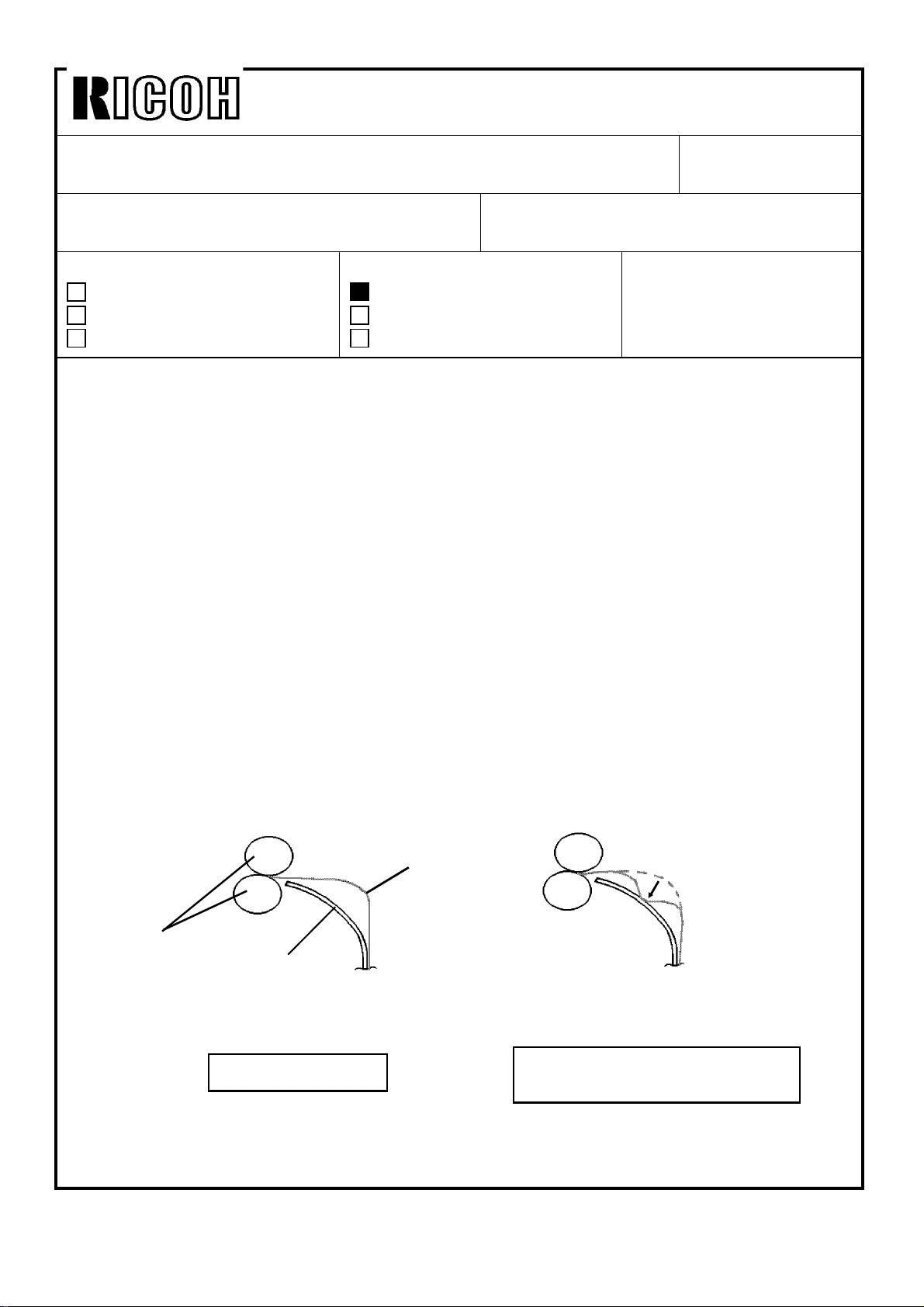
2. When the copy is made using thin paper from the 2nd feed station, noise may occur
due to double buckling. This is caused by the buckled paper hitting the turn guide
plate as shown in the illustrations
Revision of service manual
Information only
Other
FROM: Copier Technical Support Sec.
MODEL:
N220
Registration
Rollers
Turn Guide
Plate
Normal Paper Path
Paper
When the paper hits to the turn
guide plate, noise occurs.
Page 21

Technical Bulletin No. RTB-008
SUBJECT: SP Modes #45 and #46 (Paper Buckle Adjustment) DATE: Mar. 31, ’91
PAGE: 2 of 3
Mode No. Function Data
45: Buckle
Adjustment
(1st feed)
46: Buckle
Adjustment
(2nd feed)
[ SP mode #45 ]
The data of SP mode #45 must be "8" for the proper amount of paper buckle.
Do not change this value from "8".
[ SP mode #46 ]
The data of SP mode #46 is normally "8". The data is preset to eliminate double-buckle
on the production line. It is not necessary to readjust the amount of paper buckle in the
field except in the following cases:
• When the main board with the RAM board is replaced
• When the RAM board is replaced
(In these cases, all memory in the RAM board must be cleared using SP mode #99.)
Adjusts the
amount of
paper buckle in
the registration
area.
0 - 15
Factory
Setting
The data must
be "8".
(Default = 8)
2 - 8
(Default = 8)
Remarks
0.5 mm per step
Refer to
NOTE below.
If noise occurs after all memory is cleared using SP mode #99, adjust the amount of
paper buckle according to the following procedure.
- Paper buckle adjustment procedure for the 2nd feed station -
1. Make a copy to check whether or not noise occurs after SP mode #99 is done.
2. If noise occurs, decrease the data of SP mode #46 from "8". (Default value is "8".)
NOTE: 1. If the data is less than 2, paper misfeed may occur. This is because paper may
not reach the registration rollers.
2. If the data is too high, poor solid density may appear on the copy. This is
caused by the paper being creased or bent due to excessive paper buckle.
Page 22

Technical Bulletin No. RTB-008
SUBJECT: SP Modes #45 and #46 (Paper Buckle Adjustment) DATE: Mar. 31, ’91
PAGE: 3 of 3
These SP modes have been applied from the following version main board and ROM:
Main Board : A0485101E
ROM : A0485104D
The cut-in serial numbers of this software change are as follows:
MODEL NAME
Savin 9180 115/60 USA, Canada A048-15 6900700101
Nashua 3018 115/60 Canada,
Ricoh FT4418 115/60 USA, Canada A048-17 2590060001
Ricoh FT4418 110/60 Taiwan A048-19 2590070810
Nashua 3018 220,240/50 Europe. etc. A048-25 From First Production
infotec 9118Z 220,240/50 Europe A048-26 3960600001
Ricoh FT4418 220,240/50 Europe, etc. A048-27 2590060671
Ricoh FT4418 220,240/60 Philippines, etc. A048-28 From First Production
Ricoh FT4418 220,240/50 Asia A048-29 2590061231
V/Hz DESTINATION JAPAN PRODUCTION
CODE SERIAL NUMBER
L. America
A048-16 From First Production
Page 23

Technical Bulletin No. RTB-009
SUBJECT: Service Remarks for RAM Memory Clear DATE: April 30, ’91
PAGE: 1 of 4
PREPARED BY: T. Itoh
CHECKED BY:
CLASSIFICATION:
Action Required
Troubleshooting
Retrofit Information
The following problems occur due to RAM memory clear.
• Dirty background
• Paper misfeed
The RAM memory may possibly be cleared.
• Because the connection between the interface board and main board connectors
is poor.
If the DF harness is located on the interface board, a poor connection may occur
because the rear cover presses the DF harness against the interface board. If this
happens, the interface board connector may come out from the main board
connector.
• Because the following PCBs are not grounded properly
Revision of service manual
Information only
Other
FROM: Copier Technical Support Sec.
MODEL: N220
1. AC Drive Board 2. Main DC Power Supply Board
3. Optional DC Power Supply Board 4. CC/Grid/Bias Power Pack
5. TC/SC Power Pack
Each PCB is grounded by pressing the ground pattern on the PCB to the machine
frame or bracket with the screw. If the PCB is not secured correctly when
reinstalling it, the PCB is not grounded. This may generate electrical noise and this
causes RAM memory clear.
- SERVICE REMARKS -
When servicing the machine:
1. When the DF is installed, make sure that the DF harness is properly wired
and is not located on the interface board. (See page 2 - 3.)
2. Make sure that the screw used for grounding the following PCBs is properly
tightened. (See Page 4.)
1. AC Drive Board 2. Main DC Power Supply Board
3. Optional DC Power Supply Board 4. CC/Grid/Bias Power Pack
5. TC/SC Power Pack
Page 24

Technical Bulletin No. RTB-009
SUBJECT: Service Remarks for RAM Memory Clear DATE: April 30, ’91
PAGE: 2 of 4
1. DF Harness
Portion "X"
[A]
[A]
[B]
[B]
[C]
[B]
[D]
[E]
[G]
[D]
[F]
SERVICE REMARKS: When the DF is installed, make sure that the DF harness is
properly wired and is not located on the interface board.
1. Make sure that the main switch is off.
2. Place the bushing [A] at the left side of the binder [B] as shown in the illustration.
3. Place the bushing on the harness bracket [C].
[E]
NOTE: Make sure that the portion "X" of the bushing faces up.
4. Insert the DF harness [D] behind the harness support bracket [E].
5. Position the harness bracket [F] behind the harness support bracket [G] as shown.
Page 25

Technical Bulletin No. RTB-009
SUBJECT: Service Remarks for RAM Memory Clear DATE: April 30, ’91
PAGE: 3 of 4
[A]
[B]
[B]
32 cm
[H]
[C]
[D]
[C]
[I]
[E]
[F]
6. Secure the harness bracket [A] to the harness support bracket [B] (2 screws).
7. Connect the optic cable connector (2P/Black) [C] to CN206 on the interface board.
8. Connect the DC harness connector (4P/White) [D] to the optional harness connector.
9. Secure the ground wire [E] (1 screw and toothed washer).
10. Set the optional harness [F] into the clamp [G] on the main board support bracket.
(This bracket is located on the lower left side of the main board.
11. Make sure that the DF harness [H] does not pass over the interface board [I].
NOTE: Make sure that at least 32 cm of the DF harness extends out of the copier as
shown.
[G]
Page 26

Technical Bulletin
No. RTB-009
SUBJECT: Service Remarks for RAM Memory Clear
2. Grounding Screws
[
DATE: April 30,
PAGE: 4 of 4
’91
[E]
[A] : T&S Power Pack
[C] : AC Drive Board
[E] : Optional DC Power Supply Board
8
] :
The
[
(
1
SERVICE REMARKS:
\
When reinstalling the following PCBS,
i
are properly tightened.
[
screw securing the optional dc power supply board is a Philips pan head
screw. Do not use a tapping screw.
aluminum heat sink. If a tapping screw is used, the threads may be damaged.
1. AC Drive Board
3. Optional DC Power Supply Board
TC/SC Power Pack
5.
[B] : CC/Grid/Bias Power Pack
[D] : Main DC Power Supply Board
This is because
make
sure that the screws circled above [
2. Main DC Power Supply Board
4. CC/Grid/Bias Power Pack
the screw secures to an
f:)
]
Page 27

Technical Bulletin No. RTB-010
SUBJECT: Manual Correction
Belt Drive Motor Speed Adjustment
PREPARED BY: T. Itoh
CHECKED BY:
CLASSIFICATION:
Action Required
Troubleshooting
Retrofit Information
The adjustment procedure for the belt drive motor speed on the DF is missing from the
service manual. Please add the "Belt Drive Motor Speed Adjustment" section to your
manual.
NOTE: The belt drive speed adjustment is required under the following cases:
• When the main board is replaced.
• When the following problem occurs:
Revision of service manual
Information only
Other
FROM: Copier Technical Support Sec.
MODEL: N220
DATE: April 30, ’91
PAGE: 1 of 2
[Phenomenon] The belt drive motor continues to run after the original
turns over for 2nd-side copy when the original is replaced.
[Cause] Two motors are used to feed the originals. One is the belt
drive motor and the other is the feed-out motor. When the
belt drive motor speed increases, the distance between the
original fed-out (1st original) and the original fed-in (2nd
original) decreases. The feed-out sensor cannot detect the
2nd original at the proper time. This causes the belt drive
motor to run continuously.
[Countermeasure] Adjust the belt drive motor speed according to the
adjustment procedure described on next page.
NOTE: The belt drive motor speed is preset at the factory based on the 5 volts supplied
from the copier to the DF. The power supplied from the copier to the DF may vary
depending on the machine. If the power supplied from the copier increases, the
belt drive motor speed also increases. Therefore, the belt drive motor speed
should be readjusted if the above problem occurs during installation.
Page 28

Technical Bulletin No. RTB-010
SUBJECT: Manual Correction
Belt Drive Motor Speed Adjustment
Normal
Setting
[A]
[B]
DATE: April 30, ’91
PAGE: 2 of 2
[C]
1. Turn off the main switch.
2. Check that DIP switch 101 is set for the normal setting as follows:
101-1 101-2 101-3 101-4
ON OFF OFF OFF
3. Turn on the main switch and DIP switch 101-2 and -4.
4. While turning on the lift switch manually, adjust the belt drive motor speed using VR101
[A] so that both the Insert Original indicator [B] and Auto Feed indicator [C] turns off.
NOTE: a) When the Insert Original indicator lights, turn VR101 clockwise to reduce the
motor speed.
b) When the Auto Feed indicator lights, turn VR101 counterclockwise to increase
motor speed.
c) Confirm that both indicators remain off for approximately 5 seconds in order to
stabilize the motor speed.
5. Turn off DIP switch 101-2 and -4.
NOTE: Do not use VR106. This variable register is for adjusting feed-out motor speed.
This is preset by the vendor.
Page 29

Technical Bulletin No. RTB-011
SUBJECT: Software Modification DATE: June 15,’91
PAGE: 1 of 6
PREPARED BY: T. Itoh
CHECKED BY:
CLASSIFICATION:
Action Required
Troubleshooting
Retrofit Information
The software was changed (details follow) and the part numbers of the main board and the
ROM have also been changed as follows:
1. Main Board: #A0485105 #A0485121
2. ROM: #A0485104 #A0485124
(For the cut-in serial numbers, please refer to MB #42.)
Revision of service manual
Information only
Other
FROM: Copier Technical Support Sec.
MODEL: N220
Contents of Software Modification
1. Black copy problem
If a copy is made when all of the following conditions are met, the exposure lamp stays
off and machine produces a black copy.
- Conditions (1) ADF installed on the machine
a. ADF mode
b. Two or more originals set on the DF
c. The ID sensor pattern is developed when making the first copy of the last
original.
(2) Paper fed from the cassette or the manual feed table.
(3) When the original set signal from the DF is off 160 pulses (640 msec) before the
first copy paper of the last original is fed. (Refer to the table on page 4 showing the
lamp off condition.)
The software was modified to prevent black copies when the above conditions were
met.
Page 30

Technical Bulletin No. RTB-011
SUBJECT: Software Modification DATE: June 15,’91
PAGE: 2 of 6
2. AMS mode improvement
Before modification : AMS mode selects one of the fixed magnification ratios.
After modification : AMS mode selects the proper magnification ratio even if it is
not a fixed magnification ratio.
Refer to the table on page 5 or 6 for more information.
3. APS mode (USA version only)
Before modification : Check Paper Size/Direction indicator blinks when the original
size is legal (81/2x14) and the magnification ratio is between
66% and 74%.
After modification : Letter size (length wise) is selected when the original size is
legal (81/2x14) and the magnification ratio is between
66% and 74%..
4. APS mode cancellation
APS mode can be selected only when the DF is used, but in the following cases, the
APS mode is not canceled even when the DF is raised:
a. when the DF is in the SADF mode;
b. when the final original is fed and before the paper is completely out of the exit unit;
c. while scanning in the SADF mode.
The software was modified to cancel the APS mode under the above conditions.
5. Size Magnification mode improvement
A small round off error occurs if both a decimal number and a whole number are input
for the original size and copy size.
Ex.
Original Size Copy Size Magnification Ratio
7 8.5 122%
7.0 8.5 121%
(In this case, 121% should be selected.)
The formula to calculate the round off was changed to yield the proper magnification
ratio.
Page 31

Technical Bulletin No. RTB-011
SUBJECT: Software Modification DATE: June 15,’91
PAGE: 3 of 6
6. Duplex mode (1)
Before modification : The Check Paper Size indicator lights when the wrong paper
size is selected.
After modification : The Check Paper Size indicator lights and the Duplex Unit
indicator blinks when the wrong paper size is selected.
7. Duplex mode (2)
The following software bug was corrected:
If the final copy fed from the duplex unit misfeeds in the sorter section, the misfeed
condition can be reset by opening and closing the sorter after removing the misfed
paper.
However, a misfeed is still detected even if no more paper is in the duplex unit.
8. Paper tray lock condition
The following software bug was corrected:
The paper tray is still locked when the sorter misfeed condition is reset by opening and
closing the sorter.
9. Sorter bin motor free run
The following software bug was corrected:
The sorter bin motor keeps on rotating if the machine goes the following sequence, but
only if the Duplex key or 2 Single Copies key is pressed.
1) Interrupt mode selected while sorter bins are up
2) sorter bins return to their home position
3) interrupt mode canceled
4) the sorter bins return to the position they are in when the interrupt mode
is selected.
5) the sorter bin motor keeps on running when pressing the Duplex key or 2 Single
Copies key while the motor is rotating.
Page 32

Technical Bulletin No. RTB-011
SUBJECT: Software Modification DATE: June 15,’91
PAGE: 4 of 6
Combination Table
The following table shows the combinations of the paper size and original size that cause
the exposure lamp to turn off.
Original
Paper
A4S
11x8.5 OK OK OK OK OK OK
A4L
8.5x11
8.5x14 NG
A3
11x17
A4S
11x8.5 A4L 8.5x11 8.5x14 A3 11x17
NG
(65%)
NG
(77%)
(65%)
NG
(88%)
NG
(88%)
NG
(65%)
NG
(77%)
NG
(65%)
NG
(88%)
NG
(88%)
NG
(65%)
NG
(77%)
NG
(65%)
NG
(88%)
NG
(88%)
NG
(65%)
NG
(77%)
NG
(65%)
NG
(88%)
NG
(88%)
NG
(65%)
NG
(77%)
NG
(65%)
NG
(88%)
NG
(88%)
S : Sideways
L : Lengthwise
NG
(65%)
NG
(77%)
NG
(65%)
NG
(88%)
NG
(88%)
OK : The exposure lamp does not turn off in any of the selected
magnification ratios.
NG (XX%) : The exposure lamp stays off if the magnification ratio is equal to or
less than XX%.
Page 33

Technical Bulletin No. RTB-011
SUBJECT: Software Modification DATE: June 15,’91
PAGE: 5 of 6
Magnification Ration Table In AMS Mode (USA Version)
The following table shows the magnification ratios selected by the combinations of the
paper size and original size in AMS mode (before and after software change).
Paper
Original
11x17 100
11x15 100 100
8.5x14
8.5x11 129 129 100 100 65
5.5x8.5
8.5x5.5
11x8.5
11x17 11x15 8.5x14 8.5x11 5.5x8.5 8.5x5.5 11x.8.5 8.5x13 8x10
85
(*74)
121
(*100)
200
(*155) 155 155 129 100 *65 *100 *129 *100
*129
*100
100 100
*129 *100 *100 *65 100 129 *100 *93
*100
77
(*74) 65
77
(*74) 74
77
(*74)
77
(*74)
*77
(*74)
50
(*65)
50
(*65)
*50
(*65)
*50
(*65)
*50
(*65)
*50
(*65)
*50
(*65)
*50
(*65)
65 100
(*65)
(*65)
(*65)
(*74)
*50
*50
*50
*77
*74
*77
(*74)
*85
(*74)
*100
*77
(*74)
*50
(*65)
*65
*65
*85
(*74)
*65
*129
8.5x13
*129
8x10
* : Combination causing the Check Paper Size/Direction indicator to blink.
( ) : Indicates the magnification ratio selected before modification
*100 *100
*100 *100 *100 *65
85
(*74)
*65 *65 *65 100
*50
(*65)
*85
(*74)
*100 100
(*74)
*77
Page 34

Technical Bulletin No. RTB-011
SUBJECT: Software Modification DATE: June 15,’91
PAGE: 6 of 6
Magnification Ration Table In AMS Mode (Europe Version)
The following table shows the magnification ratios selected by the combinations of the
paper size and original size in AMS mode (before and after software change).
Paper
Original
A3
B4 115
A4L
A5L 200
F4
8.5X13
F
8x13
A4S
A3 B4 A4L A5L
100 82 71
(*100)
100 82
50
(*71)
50
(*71)
F4
8.5x13F8x13
71
82
65
(*71)
75
(*71)
(*71)
(*71)
141 122 100 71 100 93 *71
(*141)
122 100 82
122 100 82
*100 *82 *71
141 141 100 141 122 *100 *71 *82 122
50
(*71)
50
(*71)
*50
(*71)
100 93
100 100
*71
65
(*71)
(*71)
(*71)
A4S A5S B5S B5L B6S B6L
*50
*50
*50
(*71)
*50
(*71)
*50
(*71)
*50
(*71)
*50
(*71)
*50
(*71)
*50
(*71)
71
*82
*50
(*71)
*50
(*71)
*50
(*71)
*50
(*71)
50
(*71)
*50
(*71)
*50
(*71) *82
*50
*50
*50
(*71)
*50
(*71)
*50
(*71)
*50
(*71)
100 71 *82
*75
(*71)
*75
(*71)
50
(*71)
*50
(*71)
*50
(*71)
*50
(*71)
*50
(*71)
*50
(*71)
*50
(*71)
A5S
B5S *115
B5L
B6S
B6L 200
*141 *122 *100 *71 *100 *93 141 100 122 *82 *82
(*100)
*100 *82
*141 141
*141 *141
200
(*!41)
(*141)
115
(*100)
*115
(*!00)
*141
*50
(*71)
82
*82
115
(*100)
*82
*115
(*100)
*115
(*100)
*141 *141
*75
(*71)
115
(*100)
*100 *82
*100 *141
*115
(*100)
82 100 *71 71
*50
(*71)
115
(*100)
*71 100
141 *100 100 *71
*82 *100 141 *71 100
* : Combination causing the Check Paper Size/Direction
indicator to blink.
( ) : Indicates the magnification ratio selected before
modification
*50
(*71)
*50
(*71)
*50
(*71)
71
L : Lengthwise
S : Sideways
Page 35

Technical Bulletin No. RTB-012
SUBJECT: Drum Support Plate Replacement Procedure DATE: June 30, ’91
PAGE: 1 of 3
PREPARED BY: T. Itoh
CHECKED BY:
CLASSIFICATION:
Action Required
Troubleshooting
Retrofit Information
The following parts has been modified. (Please refer to MB #23 and #49 for the details.)
Description
Drum Support Plate A0482259 A0482260
Front Drum Side Plate A0482261 A0482263
Drum Support Plate Ass’y A0482254
The position of the following parts has been preset at the factory using the special tools.
1) Drum Support Plate (#A0482260)
2) Front Drum Support Plate (#A0482263)
3) Bias Terminal (#A0487637)
Revision of service manual
Information only
Other
P/N P/N P/N
FROM: Copier Technical Support Sec.
MODEL:
N220
MB #23 MB #49
Please refer to MB #23, for the cut-in serial numbers.
1. Concerning the drum support plate and front drum side plate:
The screws securing these parts are paint locked. Their position must not be adjusted in
the field. However, it is possible that the parts might have to be replaced in the field. To
reduce the possibility of image problems that such replacement might cause, the service
parts have been changed as follows:
The drum support plate (#A0482260) and the front drum side plate (#A0482263) have
been registered as an assembly service part (drum support plate assembly). (Please
refer to MB #49 for the cut-in serial numbers.)
2. Concerning the bias treminal:
It is difficult to reposition the bias terminal in the field if remove it. Do not loosen or
remove the screw securing the bias terminal in the field.
Please read carefully the following pages about handling the above parts in the field.
Page 36

Technical Bulletin No. RTB-012
SUBJECT: Drum Support Plate Replacement Procedure DATE: June 30, ’91
PAGE: 2 of 3
1. Drum Support Plate/Front Drum Side Plate
[C]
[D]
[E]
[B][A]
[C]
Service Remarks: 1. Do not loosen or remove the screws [D] while servicing the
machine.
2. When replacing the drum support plate [A] or front drum side
plate [B], replace them with a assembly part [C].
NOTE: Two holes [E] are added to the drum support plate so that the drum support plate
assembly [C] can be replaced in the field.
Page 37

Technical Bulletin No. RTB-012
SUBJECT: Drum Support Plate Replacement Procedure DATE: June 30, ’91
PAGE: 3 of 3
2. Bias Terminal
[A]
CAUTION: Do not loosen or remove the screw [A] securing the bias terminal.
Page 38

Technical Bulletin No. RTB-013
SUBJECT: Dust Proof Glass DATE: June 30, ’91
PAGE: 1 of 1
PREPARED BY: T. Itoh
CHECKED BY:
CLASSIFICATION:
Action Required
Troubleshooting
Retrofit Information
The dust proof glass has been modified as follows:
Old P/N New P/N
#A0481875 #A0481877
(For the cut-in serial numbers, please refer to MB #48.)
[ Reason for Modification ]
The spectral characteristics of the filter on the dust proof glass was changed to facilitate
servicing. With this modification, the light intensity passing through the filter has been
increased. The new filter can decrease the adjustment value of SP mode #48 (exposure
lamp intensity adjustment) at the factory about by 10 steps.
This increase the adjustment range of SP mode #48 in the filed.
Revision of service manual
Information only
Other
FROM: Copier Technical Support Sec.
MODEL:
N220
[ Additional Information ]
With this modification, antistatic solution has been applied to the filter surface at the
factory. This is to prevent the filter from attracting the dust in the air.
When cleaning the filter, use a dry cloth.
SERVICE REMARKS: Do not clean the filter with water or any other cleaning solution.
If do so, the antistatic effect will be lost.
Page 39

Technical Bulletin No. RTB-014
SUBJECT: Erase Function Improvement DATE: July 15, ’91
PAGE: 1 of 1
PREPARED BY: T. Itoh
CHECKED BY:
CLASSIFICATION:
Action Required
Troubleshooting
Retrofit Information
To improve the erase function in the reduction zoom mode, the eraser, eraser bracket,
and main board have been modified so that maximum side erase is 6 mm (total of both
sides) with the platen cover (10 mm with the DF).
Please refer to MB #47 for the cut-in serial numbers.
NOTE: The side erase margin when using the DF is greater than that when using the
platen cover. This is because the width of the platen cover sheet is greater than
that of the DF feed belt.
To control the new erase function, the software and ICs on the main board have been
changed, and two IC drivers have been added to the eraser board.
The old and new parts (main board, ROM, eraser, and eraser bracket) are not
interchangeable individually, but they are interchangeable as a set.
Revision of service manual
Information only
Other
FROM: Copier Technical Support Sec.
MODEL:
N220
[ Additional information ]
To distinguish the new machines from the old ones:
1) the color of the connectors used for the eraser has been changed from "White" to
"Blue".
2) the color of the lettering on the main board has been changed from "White" to
"Yellow".
3) a colored circle (diameter : 30 mm) has been printed on the side of the carton that has
"Made in Japan" printed on it.
Page 40

Technical Bulletin No. RTB-015
SUBJECT: Light or blank copy due to development drive clutch slipping DATE: Sep. 15, ’91
PAGE: 1 of 1
PREPARED BY: T. Itoh
CHECKED BY:
CLASSIFICATION:
Action Required
Troubleshooting
Retrofit Information
The development drive clutch has been modified to improve the clutch movement.
(Please refer to MB No. 56 for the cut-in serial numbers.)
If the following problem occurs in the field, the development drive clutch should be
replaced with a modified one.
Description Old P/N New P/N
Development Drive Clutch #AB040007 #AB040011
Revision of service manual
Information only
Other
FROM: Copier Technical Support Sec.
MODEL: N220
[ Phenomenon ] 1. Light Copy
2. Blank Copy
The above problem may appear after a large number of copies are
made.
[ Cause ] The development roller movement is not smooth due to
development drive clutch slipping.
After making a large number of copies, the hub surface inside of
the spring clutch may be worn out. This causes clutch slipping.
[ Countermeasure ] The hardness of the hub surface has been increased and the inner
diameter of the clutch spring has been made smaller.
[ Troubleshooting ] If a light copy or blank copy appears, check whether or not the
development roller knob rotate smoothly during copy run. If the
development roller knob does not rotate smoothly, replace the
development drive clutch with a modified one.
Page 41

Technical Bulletin No. RTB-016
SUBJECT: Noise or light copy due to toner supply clutch slipping DATE: Sep. 15, ’91
PAGE: 1 of 1
PREPARED BY: T. Itoh
CHECKED BY:
CLASSIFICATION:
Action Required
Troubleshooting
Retrofit Information
The toner supply clutch has been modified from a spring type to a magnetic type. (Refer
to MB #41 for the cut-in serial numbers.)
If the following problem occurs, the toner supply clutch should be replaced with a new one.
Old P/N New P/N Description
#A0485263 Toner Supply Clutch
#A0541116 Toner Supply Clutch Assembly
NOTE: The old and new toner supply clutches are not interchangeable. They are
interchangeable as a set. Replace the old clutch with the new clutch assembly.
Refer to MB #41 for the details.
Revision of service manual
Information only
Other
FROM: Copier Technical Support Sec.
MODEL: N220
[ Phenomenon ] 1. Noise
2. Light Copy
The above problem may appear after a large number of copies are
made.
[ Cause ] The toner supply clutch may slip due to the load from the
development unit. If the lubricating grease on the spring is
insufficient, noise may occur. If the toner supply clutch slips, toner
is not supplied to the development unit properly. This causes a
light copy.
[ Countermeasre ] The clutch type has been changed from a spring clutch to a
magnetic clutch.
[ Troubleshooting ] If noise and/or a light copy appears, check whether or not the
toner supply clutch rotates properly. If the toner supply clutch
slips, replace the clutch with a magnetic clutch.
Page 42

Technical Bulletin No. RTB-017
SUBJECT: Paper lift and sector gear slipping DATE: Sep. 15, ’91
PAGE: 1 of 1
PREPARED BY: T. Itoh
CHECKED BY:
CLASSIFICATION:
Action Required
Troubleshooting
Retrofit Information
[ Phenomenon ] When the paper stack in the cassette is lifted up, the paper lift
gear [A] and the sector gear [B] slip.
[ Cause ] The mesh between the paper lift gear and the sector gear is too
shallow.
[ Action ]
[A]
Revision of service manual
Information only
Other
Push
TO: Copier Technical Support Section
MODEL: N220
No Gap
1. Turn off the main switch.
2. Make sure that the cassette is installed on the copier and the manual feed table is
closed.
3. Remove the rear cover and the main board.
4. Loosen the screw [C].
5. Retighten the screw while pushing down the paper lift clutch support bracket [D] so
that there is no gap between the pitch circles of the paper lift gear and the sector gear.
6. Reassemble all parts previously removed.
NOTE: When the paper lift clutch support bracket is removed during servicing, the
bracket must be reinstalled according to the above procedure.
[B]
[D]
[C]
Page 43

Technical Bulletin No. RTB-018
SUBJECT: Troubleshooting Guide (1. Dark copy 2. RAM data clear
3. Dirty background (over torning)
PREPARED BY: T. Itoh
CHECKED BY:
CLASSIFICATION:
Action Required
Troubleshooting
Retrofit Information
This troubleshooting guide is developed to assist your daily service activity for the N220
copier based on the investigation of field machines, the analysis of service calls.
This troubleshooting guide may not pertain to all the cases which you may encounter in
the field, however, it covers typical causes for the following:
SECTION 1 DARK COPY
SECTION 2 RAM DATA CLEAR
Revision of service manual
Information only
Other
TO: Copier Technical Support Section
MODEL: N220
DATE: Oct. 15, ’91
PAGE: 1 of 11
SECTION 3 DIRTY BACKGROUND AND/OR TONER SMUDGE ON THE
LEADING EDGE OF THE COPY (OVER TONING)
Page 44

Technical Bulletin No. RTB-018
SUBJECT: Troubleshooting Guide (1. Dark copy 2. RAM data clear
3. Dirty background (over torning)
DATE: Oct. 15, ’91
PAGE: 2 of 11
1. DARK COPY
SYMPTOM:
Copies have dirty background prematurely and customer needs to shift manual image
density level to lighter selection.
CAUSE:
An air flow through the 6th mirror area carries and accumulates dust on the surface of the
6th mirror [A] and of the filter on the toner shield glass [B].
Static electricity is produced on the surface of the filter by cleaning it with dry cloth. It will
remain on the surface of the filter and will accelerate accumulation of dust.
[A]
[B]
SOLUTION:
1. Clean all optics parts.
2. Apply the antistatic solution to the filter on the toner shield glass.
3. Install the shield mylar. (See SHIELD MYLAR INSTALLATION PROCEDURE.)
Page 45

Technical Bulletin No. RTB-018
SUBJECT: Troubleshooting Guide (1. Dark copy 2. RAM data clear
3. Dirty background (over torning)
SHIELD MYLAR INSTALLATION PROCEDURE:
Units Affected:
A shield mylar has been applied to the production units. Refer to MB No. 51 for the cut-in
serial numbers.
Necessary Part:
Part No. Description Q’ty
A0489505 Shield Mylar 1
[B]
[D]
[A]
Ozone
DATE: Oct. 15, ’91
PAGE: 3 of 11
6th Mirror
[C]
Charge Corona Unit
1. Open the front cover and lower the transport unit.
2. Remove the following parts:
a. Cleaning Unit
b. Development Unit
c. Charge Corona Unit
d. Drum Unit (Protect the drum surface with a protective sheet.)
3. Place the cutout [A] face down on the dust shielding mylar [B] and completely insert it
into the gap between the cleaning rail [C] and the upper cleaning stay [D] as shown.
CAUTION: The cutout on the mylar must be inserted face down into the gap. If the
cutout is face up, the ozone stays around the charge corona unit. This may causes
a foggy image, lighter image, or dirty background problem.
Page 46

Technical Bulletin No. RTB-018
SUBJECT: Troubleshooting Guide (1. Dark copy 2. RAM data clear
3. Dirty background (over torning)
DATE: Oct. 15, ’91
PAGE: 4 of 11
4. Remove the toner shielding glass [E] from the copier.
5. Clean the toner shielding glass and the filter [F] with a dry cloth.
6. Damp a clean and soft cloth with a small amount of antistatic solution.
7. Wipe the filter with the cloth.
[F]
NOTE: You can use any commercially available antistatic solution. If this solution is not
available, wipe the surface of the filter with your finger to remove static electricity
as shown below:
[E]
CAUTION: Do not clean the filter with water or any other cleaning solution after
this. If you do so, the antistatic effect will be lost.
8. Clean the following parts:
• 1st, 2nd, 3rd, 4th, 5th, and 6th Mirrors
• Lens
• Reflectors
• Exposure glass
WARNING: Be careful not to cut your fingers when you clean the 6th mirror. The edges
are sharp.
9. Reassemble the copier.
10. Adjust the lamp intensity by SP mode #48.
11. Adjust the ADS voltage by SP mode #56 and VR101 on the main board.
Page 47

Technical Bulletin No. RTB-018
SUBJECT: Troubleshooting Guide (1. Dark copy 2. RAM data clear
3. Dirty background (over torning)
DATE: Oct. 15, ’91
PAGE: 5 of 11
2. RAM DATA CLEAR
SYMPTOM:
The following typical symptoms may occur when and after the SP mode data is reset by
electrical noise.
• Dark copies are made suddenly. (The data of SP mode #48 [light intensity adjust-
ment] resets to "126".)
• Paper misfeed (The data of SP mode #45 [1st feed paper buckle adjustment] and
#46 [2nd feed paper buckle adjustment] reset to "0".)
CAUSE:
The following possible causes may generate electrical noise and reset the CPU and the
SP mode data in the RAM board;
• Poor connection between the main board and the interface board
• The following PCBs are not grounded properly;
1. AC Drive Board
2. Main DC Power Supply Board
3. Optional DC Power Supply Board
4. TC/SC Power Pack
5. CC/Grid/Bias Power Pack
NOTE: These PCBs are grounded by pressing the printed pattern on the PCBs to the
machine frame or bracket with screws.
• Current leakage in the separation corona or the transfer corona
Page 48
Technical Bulletin No. RTB-018
SUBJECT: Troubleshooting Guide (1. Dark copy 2. RAM data clear
3. Dirty background (over torning)
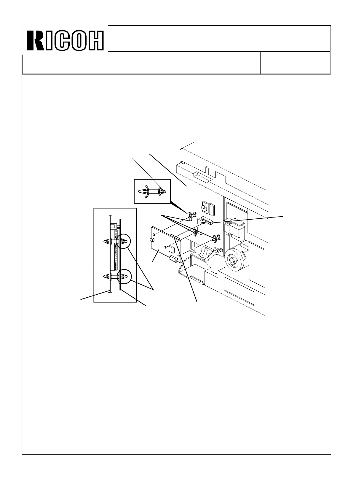
SOLUTION:
1. If the interface board is installed, make sure of the following:
a. The smaller side [A] of the locking supports must be inserted through the main
board [B].
b. The heads of the three locking supports must firmly lock the main board [B] and
interface board [C] together as shown.
[B]
[A]
[A]
DATE: Oct. 15, ’91
PAGE: 6 of 11
[E]
[C]
[A]
[B]
[C]
c. The connector [D] of the interface board must be connected firmly to the main
board connector [E].
d. If the document feeder is installed, make sure that the DF harness is properly wired
and is not located on the interface board. (Refer to RTB-009 for detailed information.)
2. Make sure that the screws used for grounding the following PCBs are properly
tightened. (Refer to RTB-009 for detailed information.)
a. AC Drive Board
b. Main DC Power Supply Board
c. Optional DC Power Supply Board
d. CC/Grid/Bias Power Pack
e. TC/SC Power Pack
[D]
Page 49

Technical Bulletin No. RTB-018
SUBJECT: Troubleshooting Guide (1. Dark copy 2. RAM data clear
3. Dirty background (over torning)
3. Troubleshoot the current leakage in the separation corona or the transfer corona.
a. Check the transfer and separation corona end block and/or receptacle for current
leaks.
b. If there are leaks, replace the corona end block or the receptacle.
c. To prevent the SP mode data from being reset by current leaks in the future, install
ferrite cores on the high voltage cables for the transfer corona and the separation
corona. (See FERRITE CORE INSTALLATION PROCEDURE.)
4. Reset the following SP mode data to the factory setting.
SP
mode
21 APS Priority 1
41 Leading Edge Erase See NOTE 1
42 Leading Edge Registration See NOTE 1
Function Factory Setting
Data
DATE: Oct. 15, ’91
PAGE: 7 of 11
43 Vertical Magnification See NOTE 1
44 Horizontal Magnification See NOTE 1
45 1st Feed Paper Buckle 8
46 2nd Feed Paper Buckle 8
47 Focus See NOTE 1
62 ID Sensor Grid 7 (See NOTE 2)
71 Sorter Operation 1 (See NOTE 3)
76 Sorter Bin Capacity 1
NOTES: 1. Factory setting data of SP #41, 42, 43, 44, and 47 are recorded on the factory
setting sheet located in the left inner cover.
2. It is necessary to reset the data of SP mode #62 only for the machines which
have the S/N 259005XXXX.
3. This is necessary only for the machines which have the sorter.
5. Perform SP mode #68 (Vr forced detection) and make 5 copies. Making these 5
copies insures the proper Vr correction data based on the current drum condition.
6. Adjust the exposure lamp intensity by SP #48.
7. Adjust the ADS voltage by SP #56 and VR101 on the main board.
Page 50

Technical Bulletin No. RTB-018
SUBJECT: Troubleshooting Guide (1. Dark copy 2. RAM data clear
3. Dirty background (over torning)
FERRITE CORES INSTALLATION PROCEDURE:
Units Affected:
Ferrite cores have been installed on the production units. Refer to MB No. 53 for the cut-in
serial numbers.
Necessary Part:
Part No. Description Q’ty
16070478 Ferrite Core 3
DATE: Oct. 15, ’91
PAGE: 8 of 11
[D]
[B]
[C]
[A]
1. Turn off the main switch and remove the rear cover.
2. Install one ferrite core [A] on the high voltage cable [B] for the transfer corona.
3. Install two ferrite cores [C] on the high voltage cable [D] for the separation corona.
4. Reinstall the rear cover.
Page 51

Technical Bulletin No. RTB-018
SUBJECT: Troubleshooting Guide (1. Dark copy 2. RAM data clear
3. Dirty background (over torning)
DATE: Oct. 15, ’91
PAGE: 9 of 11
3. DIRTY BACKGROUND AND/OR TONER SMUDGE ON
THE LEADING EDGE OF THE COPY (OVER TONING)
SYMPTOM:
• The background of copies has small speckles (toner particles). This dirty background
remains even when a different image density is selected (Notch 1 through 7).
• The copy leading edge has toner smudges.
CAUSE:
The toner density in the development unit is too high. The following are possible causes:
• The RAM data clear problem has happened before.
• The ID sensor pattern is not developed properly.
SOLUTION:
1. To find out if the RAM data clear problem has happened before, check the data of SP
#45 and 46 (paper buckle adjustment). If they are "0", the RAM data has been cleared
before. (See SECTION 2. RAM DATA CLEAR.)
2. Check whether the ID sensor pattern is developed properly or not. If not, install the ID
sensor pattern patch. (See ID SENSOR PATTERN PATCH INSTALLATION
PROCEDURE.)
3. Replace the developer and perform the developer initial setting (SP #65).
NOTE: Even after performing the above procedures, the toner density may still be too
high. Therefore, replace the old developer with fresh one.
Page 52

Technical Bulletin No. RTB-018
SUBJECT: Troubleshooting Guide (1. Dark copy 2. RAM data clear
3. Dirty background (over torning)
ID SENSOR PATTERN PATCH INSTALLATION PROCEDURE:
Units Affected:
The ID sensor pattern has been enlarged from the March 1991 production.
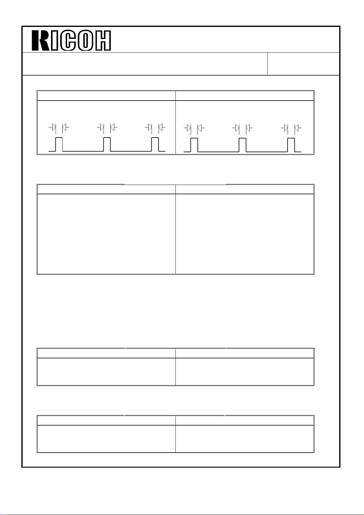
1. Confirmation Procedure
OK No Good
DATE: Oct. 15, ’91
PAGE: 10 of 11
ID Sensor Pattern Image
1. Turn off the main switch.
2. Remove the rear cover (4 screws).
3. Turn on the main switch.
4. Connect CN111-1 to TP112 (GND) with a jumper wire so that the registration clutch
stays on.
CAUTION: Do not connect CN111- 2 to TP112 (GND). If you do so, the fuse (FU101)
on the main DC power supply board will be blown.
5. Select the paper tray (the 2nd feed station) by pressing the select paper key.
6. Make 10 copies and then find a copy with the ID sensor pattern copied.
NOTE: The ID sensor pattern is a halftone image.
7. Reassemble the copier.
8. If the ID sensor pattern image is no good, install the ID sensor pattern patch. (See
next page for the procedure.)
Page 53

Technical Bulletin No. RTB-018
SUBJECT: Troubleshooting Guide (1. Dark copy 2. RAM data clear
3. Dirty background (over torning)
2. ID Sensor Pattern Patch Installation Procedure
Necessary Part:
Part No. Description Q’ty
A0489506 ID Sensor Pattern Patch 1
[C]
[E]
[B]
DATE: Oct. 15, ’91
PAGE: 11 of 11
[F]
[H]
[G]
[D]
[A]
1. Turn off the main switch.
2. Remove the left scale (2 screws), and then remove the exposure glass.
3. Move the first scanner so that the ID sensor pattern [A] on the left scale bracket [B] is
reflected by the back side of the 2nd mirror [C] as shown in the illustration.
4. Attach the ID sensor pattern patch [D] to the left scale bracket.
NOTES: 1. Make sure that the side edges of the ID sensor pattern patch are aligned with
those of the ID sensor pattern printed on the left scale bracket.
2. Make sure that the leading edge of the ID sensor pattern patch [E] is aligned
with the edge [F] of the left scale bracket.
3. Make sure the cutout [G] on the ID sensor pattern seal is released from the
screw hole [H] on the left scale bracket.
4. Reassemble the copier.
Page 54

RICOH
Technical Bulletin
No.
RTB-019
SUBJECT: New procedure for the DG (doctor gap) adjustment
PREPARED BY:
CHECKED BY:
“.,.
CLASSIFICATION
-
FROM: Copier Technical Support Section
MODEL: N220
DATE: Jan. 31, ’92
PAGE: 1 of 6
❑ Action Required ■ Revision of service manual
❑ Troubleshooting
❑ Information only
❑ Retrofit Information ❑ Other
The DG adjustment standard in the factory has been changed from 0.53 -- 0.67mm to
0.63 - 0.72mm from the July ’91 production onward. This is to minimize image
overtoning and toner scattering. These problems are due to the DG being too narrowly
adjusted.
When you are forced to adjust the DG in the field, adjust it with the new DG gauge (P/N
A0489507) and refer to the following procedure.
NOTE: If the current development unit has no problem with the DG adjusted to the old
standard, do not re-adjust it to the new standard.
This procedure supersedes the doctor gap adjustment procedure in the service manual.
Page 55

RICOH
SUBJECT: New procedure for the DG (doctor gap) adjustment DATE: Jan. 31, ’92
NEW PROCEDURE:
CAUTION: The doctor gap was adjusted at the factory using the special
tool. Therefore, normally this adjustment is not required in the field.
Only when the development unit is disassembled or the development
roller is replaced, this adjustment is required.
1. Confirmation Procedure
Technical Bulletin
No.
RTB-019
PAGE: 2 of 6
1. Take out the development unit.
2. Remove the developer.
3. Remove the inlet seal plate [A] by working a small blade screwdriver along the edge of
the plate while pressing the stoppers [B] with one finger as shown.
CAUTION: Be careful not to damage the stoppers [B] when removing the inlet seal
plate.
4. Clean the development roller [C] with a vacuum cleaner until no developer is left on
the roller. Turn the roller to make sure that it is free of developer.
NOTE: This prevents surface damage to the roller and ensures an accurate adjustment.
Page 56

Technical Bulletin
No. RTB-019
SUBJECT: New procedure for the DG (doctor gap) adjustment
DATE: Jan. 31, ’92
PAGE: 3 of 6
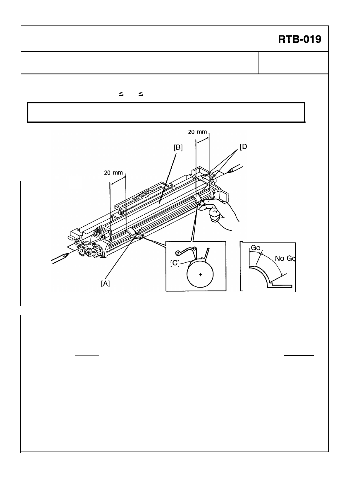
5. Position the DG gauge (P/N #A0489507) 20 mm (0.8 inch) from the front end of the
development roller, and insert the gauge into the doctor gap until it stops.
I
CAUTION:
Do not force the DG gauge into the gap and do not press the gauge too
hard on the roller. The roller should not rotate when you insert the
gauge into the gap.
—
Page 57

RICOH
Technical Bulletin
No.
RTB-019
SUBJECT: New procedure for the DG (doctor gap) adjustment
6. Check the doctor gap at four points
turning the development roller 90° each
time.
If the “GO” part of the DG gauge goes
through the doctor gap, and the “NO GO”
part does not go through, the gap at this
point is: 0.63 mm s DG s 0.72 mm
If the “GO” part of the
go through the doctor gap, the gap at this
point is:
DG
<
0.63 mm
If both “GO” part and “NO GO” part go
through the doctor gap, the gap at this
point is: DG
>0.72
DG gauge does not
mm
DATE: Jan.
PAGE:
Good
Too
Too wide
4
of 6
narrow
31, ’91
7. Repeat steps 6 and 7 for the rear side of the development roller.
8. If either 3 out of 4 checked points or all 4 points are “0.63 mm
gap is in good condition. If more than 2 out of 4 checked points are
adjust the
DG only when there is any of the following problems:
a. Severe jitter copy
b. Blocking of development drive mechanism
c. Developer leakage
DG. If more than 2 out of 4 checked points are “DG > 0.72 mm” adjust the
s
DG s 0.72 mm”, the
“DG <0.63
mm”,
Page 58
RICOH
Technical Bulletin
No.
RTB-019
SUBJECT: New procedure for the DG (doctor gap) adjustment
2.
Adjustment Procedure
Adjustment standard :0.63 s DG s 0.72
CAUTION: Before adjusting the doctor gap, the confirmation procedure must be
performed.
DATE: Jan. 31, ’92
PAGE: 5 of 6
1
7
4
1. Clean the development roller [A] with a vacuum cleaner until no developer is on the
roller. Turn the roller to make sure that it is free of developer.
2. Loosen the doctor plate [B] (4 screws).
3. Insert the “NO GO” part of the gauge [C] in the doctor gap 20 mm from the front side
of the development roller as shown.
NOTE: The front side should be adjusted first to prevent the doctor gap from being too
narrow.
4. Press down the doctor plate directly above the gauge, and tighten the front doctor
plate screws [D].
NOTE: Do not press the doctor plate too hard, the doctor gap will become too narrow.
5. Repeat the adjustment procedure at the rear side of the development roller.
6. Confirm that the doctor gap is adequate by following the confirmation procedure.
Page 59

RICOH
Technical Bulletin
No.
RTB-019
SUBJECT: New procedure for the DG (doctor gap) adjustment
The machine serial numbers cut-in are as follows:
CODE
A048-15
A048-16 Nashua 3018 2111070001
A048-17
A048-19
A048-25 Nashua 3018 2101070001
A048-26
A048-27
A048-28
A048-29
A048-46
A048-47
MODEL NAME
Savin
9180 6910904704
Ricoh
FT4418
Ricoh
FT4418 2591070490
Infotec
Ricoh
Ricoh FT4418 259201XXXX
Ricoh
Infotec
Ricoh FT4418
9118Z
FT4418 2591070560
FT4418 2591070762
9118Z
SERIAL NUMBER
DATE: Jan. 31, ’92
PAGE: 6 of 6
2591070001
3960710001
3966410001
2591640001
Page 60

REVISED ON SEPTEMBER 30, ’93
Technical Bulletin No. RTB-020
SUBJECT: Lubrication of the idle gear and the idle gear shaft. DATE:
Feb. 28, 1 993
PAGE: 1 of 2
PREPARED BY: N. Takai
CHECKED BY:
CLASSIFICATION:
Action Required
Troubleshooting
Retrofit Information
A rattling noise comes out from the idle gear engagement or jitter images appear about
100 K to 150 K copies after machine installation. This is because the shaft of the idle
gear-35 Z (P/No. AB013434) is being worn out gradually and the gear engagement
becomes poor.
To prevent this problem, the gear shaft and the gear’s teeth should be lubricated at your
next visit, and the gear teeth at every PM interval afterwards, according to the following
procedure:
- Action required -
Revision of service manual
Information only
Other
FROM: Copier Technical Support Section
MODEL: N220
1. Remove the rear cover (4 screws).
2. Remove the fusing drive release
spring [A].
3. Remove the main motor ass’y [B]
(4 screws and 1 connector)
[A]
[B]
Page 61

Technical Bulletin No. RTB-020
SUBJECT: Lubrication of the idle gear and the gear shaft. DATE:
Feb. 28, 1 993
PAGE: 2 of 2
4. Remove the E-ring [C] and the washer
[D] from the idle gear shaft.
5. Lubricate the gear’s teeth with Grease
G-501 [E] and the gear shaft with the
spindle oil [F].
[D]
6. Reassemble.
[F]
* Confirm that the fusing drive release
spring [A in page 1] is set. If this
spring is not set, drive cannot
transmitted to the fusing section.
NOTES: (1) For the field machines having this problems, we recommend replacing the idle
gear with the modified one (new P/No. AB013841). (Refer to M/B # 87. )
(2) When the modified gear is installed, the two washers (P/No. 52031870 [G] and
08075074 [H]) should be installed together in the order illustrated.
* Since the modified gear has ball-bearings inside instead of dry-bearings, this
gear works even if the shaft is worn out.
[C]
[E]
[H]
[G]
Page 62

Technica l Bulletin No . RTB-02 1
[C]
SUBJECT: N o m an ual fee d o p er atio n DATE: Ap r il 30, ’93
PAGE: 1 o f 1
PREPARED BY: N . Tak ai
CHECKED BY:
CLASSIFICATION:
Action Required
Troubleshooting
Retrofit Information
For the machine with the cassette, the manual feed function does not op erate. Th e manual
feed indicator does not appear on the operation panel, even when the manual feed table
is opened.
This is because the manual feed switch is not activated sufficiently.
- Action required -
1. Remove the copier left cover [A] (4
screws), the key counter cover [B] (2
scr ews) and t he fixing p late [C] .
2. Install the cassette and close the
manual feed table.
Revision of service manual
Information only
Other
FROM: Copier Technical Support Sec.
MODEL: N220
[A]
3. With the screw driver, bend the
manual feed switch bracket [D]
slightly downward (about 1mm) as
shown in the illustration.
This reduces the clearance between
the switch and the release lever.
NOTE: After bending the bracket,
make sure that the switch does not
touch the release lever [E] .
4. Open the manual feed table and
confirm that the manual feed indicator
in the operation panel lights up.
5. Reassemb le the c o pier .
[B]
[D]
[E]
[D]
Page 63

Technical Bulletin No. RTB-022
4±1mm
SUBJECT:
New procedure for the Cleaning Unit Entrance Seal Replacement
PREPARED BY: J. Kasamoto
FROM: Copier Technical Support Section
DATE: 15 Sep. ’93
PAGE: 1 of 2
CHECKED BY:
CLASSIFICATION:
Action Required
Troubleshooting
Retrofit Information
Revision of service manual
Information only
Other
MODEL: N220
The cleaning unit entrance seal has been modified to standardize with the A7 and Pigeon
series. Because of this modification, the entrance seal replacement procedure is changed
as follows:
New PROCEDURE
ENTRANCE SEAL REPLACEMENT
[B]
[A]
4.5±0.5mm
[C]
[F]
[J]
1±1mm
[C]
[G]
[D]
[E]
4±1mm
[H]
[I]
1. Remove the cleaning unit and the following parts:
• Cleaning Blade
• Cleaning Brush
2. Remove the used toner. (See Used Toner Collection.)
3. Clean the cleaning unit with a vacuum cleaner.
[J]
4. Remove the entrance seal [A] together with the strip of 2 sided tape securing it to the
lower casing.
Page 64

Technical Bulletin No. RTB-022
SUBJECT:
New procedure for the Cleaning Unit Entrance Seal Replacement
5. Clean the lower casing [B] with alcohol: make sure that no tape remains on the casing
surface.
6. Place a new strip of 2-sided tape [C] on the lower casing surface as shown in the
illustration. The upper edge [D] of the tape must be flush with the edge [E] of the
projection as shown in the illustration.
7. Place the new entrance seal [F] on the 2-sided tape as shown in the illustration.
NOTE: a) The lower edge [G] of the entrance seal must be aligned with the edge [H] of
the lower casing.
b) Make sure that there are no waves in the upper edge [I] of the entrance seal.
8. Place the new side seals [J] on the entrance seal as shown. Bend and stick the trail
edge of the s eal to the bo ttom casi ng.
DATE: 15 Sep. ’93
PAGE: 2 of 2
Page 65

Technical Bulletin No. RTB-023
SUBJECT: Gear Teeth Damage DATE: 15 Sep. ’93
PAGE: 1 of 1
PREPARED BY: J. Kasamoto
CHECKED BY:
CLASSIFICATION:
Action Required
Troubleshooting
Retrofit Information
– Symptom –
The 2 gears engaged to the gear (P/N AB013201) on the hot roller shaft gets damaged.
– Cause –
The gear on the hot roller shaft is positioned in a way that does not allow it to properly
engage the gears above it.
– Solution –
Perform the following procedure when this symptom occurs or at the next PM cycle:
Remove the gear from the hot roller shaft and reinstall it so that the boss faces out and
the gears engage properly (see illustration).
Revision of service manual
Information only
Other
FROM: Copier Technical Support Section
MODEL: N220
Before After
Page 66

Technical Bulletin No. RTB-024
SUBJECT: Development Unit Idle Gear DATE:July 31, ’95
PAGE: 1 of 1
PREPARED BY: N. Kaiya
CHECKED BY:
CLASSIFICATION:
Action Required
Troubleshooting
Retrofit Information
The 15z gear has been changed from AB013438 to AB013858 as informed by Modification
Bulletin No. 95 dated October 15, 1993. The material of the gear has been changed to a
non-conductive type to prevent leaking of the development bias through this gear.
In some countries, the consumption of the old gear (AB013438) is still high compared to
that of the new gear. (The old gear can still be used with E7 machines produced before
modification of this gear.)
When you need to replace the 15z gear in the field, could you please make sure to use
the new gear , P/N AB0138 58.
Revision of service manual
Information only
Other
FROM: 2nd Technical Support Section
MODEL:
N220
Gear - 15Z
 Loading...