

Page 1
MODIFICATION BULLETIN NO. 9 Page 1 of 2 ISSUED ON: Nov. 15, ’90
Model NC11 Volt/Hz
Modified Article Cable Guide Plate
Reason for
To ensure the smooth movement of the exposure lamp harness
Modification
Old Parts No. New Parts No. Description Q’ty used
---- A0301697 Cable Guide Plate 0 ---- 1 #48 (New) 1 - 33
Parts Catalog Index
No.
#33
#24
Page
Date of
Modification
Serial Number
#102
P/C1-53
#104
#48
(New)
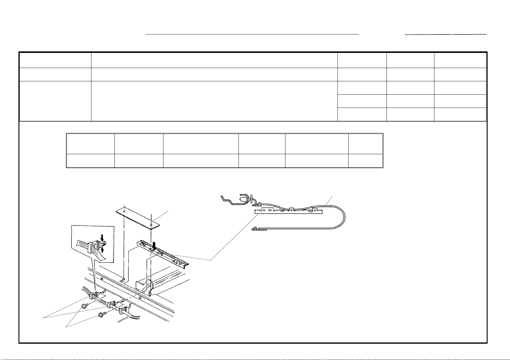
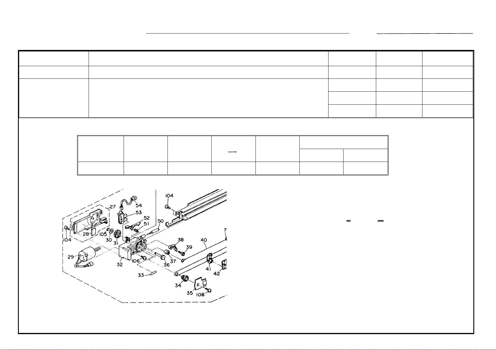
To ensure the smooth movement of the exposure lamp harness (#33), the
cable guide plate (#48, a new index) is newly installed on the front optics
frame as shown.
This plate is located under the lamp harness, and keeps it to be flat while
scanning.
T.Ito, Manager
Copier Technical Support
Page 2

MODIFICATION BULLETIN NO. 9 Page 2 of 2 ISSUED ON: Nov. 15, ’90
MODEL NAME
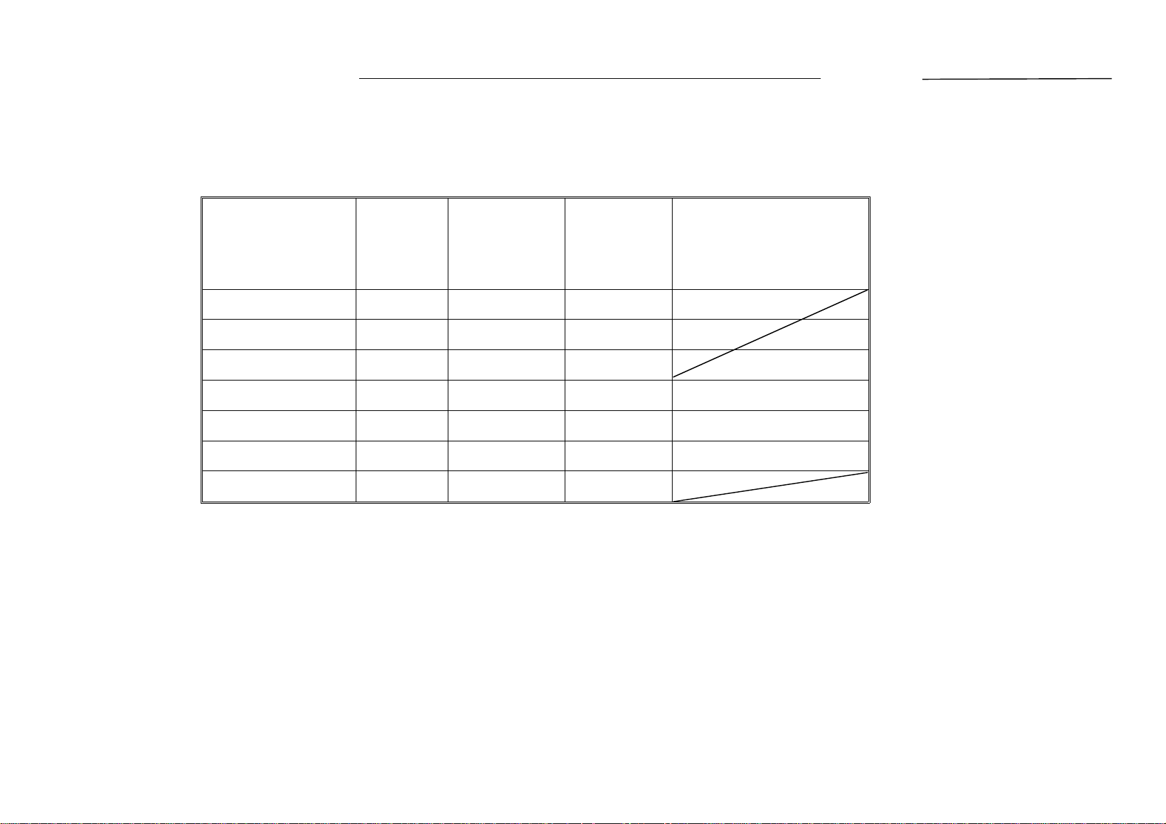
NASHUA C240 115/60 USA, CANADA A030 - 16 186010XXXX
RICOH NC100 115/60 USA, CANADA A030 - 17 2520100001
RICOH NC100 110/60 TAIWAN A030 - 19 2520090144
NASHUA C240 220, 240/50 EUROPE, etc. A030 - 25 1850090081
INFOTEC 7125 220, 240/50 EUROPE A030 - 26 3910900051
RICOH NC100 220, 240/50 EUROPE, etc. A030 - 27 2520090459
RICOH NC100 220/50 ASIA A030 - 29 2520090478
V/Hz DESTINATION CODE SERIAL NUMBER
Page 3

Reissued on : February 28, ’91
MODIFICATION BULLETIN NO. 10 Page 1 of 3 ISSUED ON: November 30, ’90
Model NC11 Volt/Hz
Modified Article Paddle Roller
Reason for
To increase the duarability
Modification
Draw
No.
Old
Parts No.
〈 Black Development Unit 〉
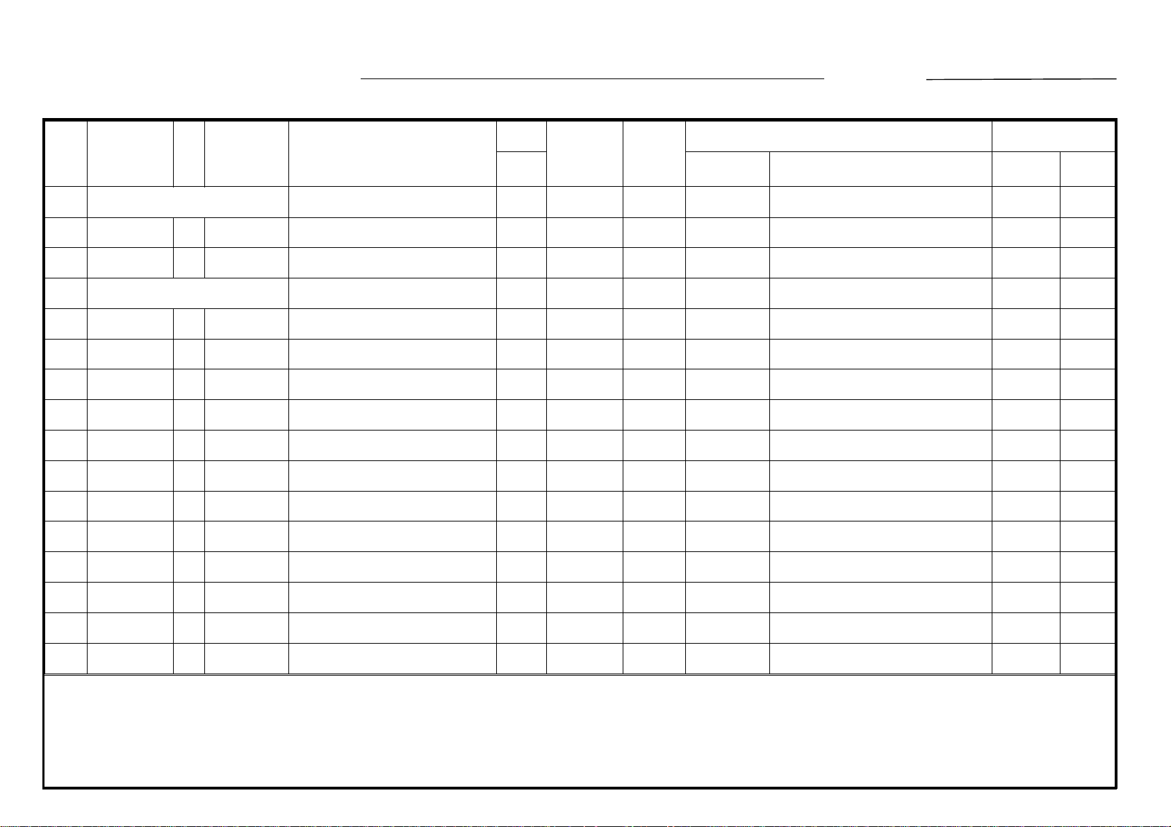
AD038012 AD038029 Paddle Roller 1 ---- 1 X/X 43 1 - 39
A0303065 A0303068 Rear Side Plate - Development 1 ---- 1 X/X 12 1 - 39
AB013253 AB013520 Gear - 44Z 1 ---- 1 X/O 17 1 - 39
New
Parts No.
AA152167 Rubber Bushing 10.5 x 16.5 x 5.5 0 ---- 1 *67 1 - 39
A0303071 Bearing Retainer - Paddle 0 ---- 1 X/O as a set *68 1 - 39
Description
Date of
Modification
A.B.C.
Rank Part No. Description Index No. Page
Q’ty Used
Old → New
Inter-
change-
ability
Part needed for replacement by new part Parts Catalog
Serial Number
07250120E Retaining Ring - M12 6 ---- 7 105 1 - 39
03130060W Philips Head Screw M3 x 6 4 ---- 6 104 1 - 39
〈 Color Development Unit 〉
AD038012 AD038029 Paddle Roller 3 ---- 3 X/X
AB013241 AB013519 Gear 40Z 3 ---- 3 X/O 18 1 - 43
Rank: A : Replace with new parts immediately. B : Replace with new parts at time of repair. C : Replace with new parts at time of overhall.
Interchangeability:
(1) When old and new parts are not mutually interchangeable, use additional parts or an assembly part as indicated in "Parts needed for replacement by new part" to
install the new part.
(2) The mark to the left of the slash indicates whether the old part can be used in the new machine, and the mark to the right indicates whether the new part can be used
in the old machine. x = Not interchangeable o = Interchangeable
X/O as a set
* New Index
5 1 - 43
Page 4
DETAILS OF MODIFICATION
#67 (New)
MODIFICATION BULLETIN NO. 10 Page 2 of 3 ISSUED ON: November 30, ’90
#105 (New)
#12
#104 (New)
#68 (New)
(#117)
(#105)
#17
Reissued on : February 28, ’91
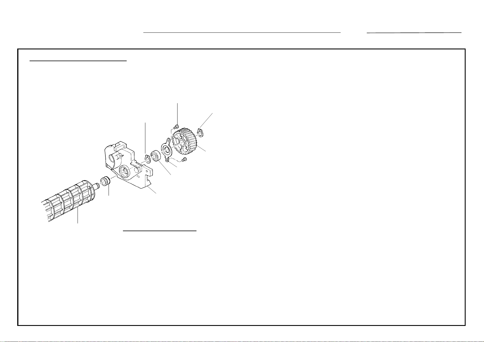
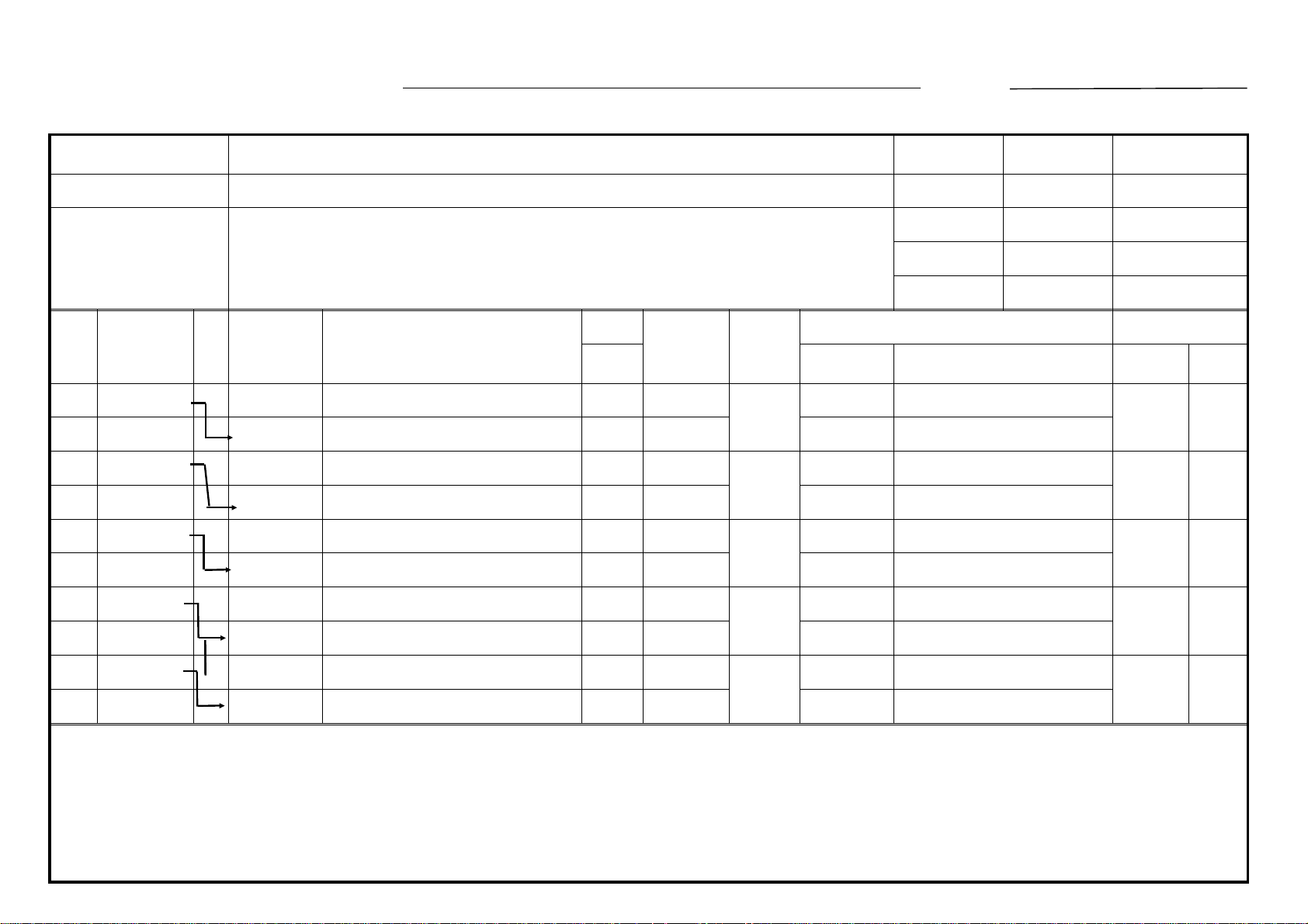
To increase the durability, the material and surface treatment of the front
and rear flanges on the paddle roller [#43] are changed.
[For the black development unit]
At the same time, the rubber bushing [#67] is newly installed on the rear
side to ensure the seal function. Due to these changes, the rear side
plate [#12] is also changed. A retaining ring (C-ring M12) [#105] and the
bearing retainer [#68] are added on the rear frange of the puddle roller.
To get the space for the bearing retainer, the width of the gear - 44Z
(#17) is changed from 15.5mm + 14.5mm.
Note : * The old paddle roller and the old rear side plate are still
available for the machines with the old parts.
* When either the old paddle roller or the old rear side plate in the
black development unit is replaced with a new type replace the
other five parts with new ones as a set.
#43
Black Development Unit
[For the color development unit]
Due to the new puddle roller, the gear - 40Z [#18] is also changed.
Note : When the old paddle roller in the color development unit
is replaced with the new type, replace the gear - 40Z with a new
type, too, as a set.
T. Ito, Manager
Copier Technical Support
Page 5

Reissued on : February 28, ’91
MODIFICATION BULLETIN NO. 10 Page 3 of 3 ISSUED ON: November 30, ’90
MODEL NAME
NASHUA C240 115/60 USA, CANADA A030 - 16 186011XXXX
RICOH NC100 115/60 USA, CANADA A030 - 17 252011XXXX
RICOH NC100 110/60 TAIWAN A030 - 19 252011XXXX
NASHUA C240 220, 240/50 EUROPE, etc. A030 - 25 185011XXXX
INFOTEC 7125 220, 240/50 EUROPE A030 - 26 3911100001
RICOH NC100 220, 240/50 EUROPE, etc. A030 - 27 2520110001
RICOH NC100 220/50 ASIA A030 - 29 2520110136
V/Hz DESTINATION CODE SERIAL NUMBER
Page 6
MODIFICATION BULLETIN NO. 11 Page 1 of 3 ISSUED ON: November 30, ’90
Model NC11 Volt/Hz
Modified Article Transfer Drum Ring
Reason for
To accept a new shipping retainer stad
Modification
Draw
No.
Old
Parts No.
A0306066 A0306067 Transfer Drum Ring 1 ---- 1 O/O 9 1 - 23
New
Parts No.
Description
Date of
Modification
A.B.C.
Rank Part No. Description Index No. Page
Q’ty Used
Old → New
Inter-
change-
ability
Part needed for replacement by new part Parts Catalog
Serial Number
Rank: A : Replace with new parts immediately. B : Replace with new parts at time of repair. C : Replace with new parts at time of overhall.
Interchangeability:
(1) When old and new parts are not mutually interchangeable, use additional parts or an assembly part as indicated in "Parts needed for replacement by new part" to
install the new part.
(2) The mark to the left of the slash indicates whether the old part can be used in the new machine, and the mark to the right indicates whether the new part can be used
in the old machine. x = Not interchangeable o = Interchangeable
Page 7
DETAILS OF MODIFICATION
MODIFICATION BULLETIN NO. 11 Page 2 of 3 ISSUED ON: November 30, ’90
#8
Old stad
M4 Screw hole
# 9
(New : A0306067)
103
New stad
5mm hole
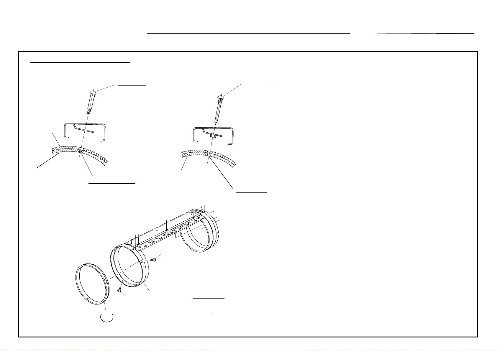
The shipping retainer stad to prevent the transfer
drum from turning is changed.
For this change, the transfer drum ring (#8) is also
changed;
Old : The ring has a M4 screw hole to be fired with
the old stad.
New : It has a just 5mm hole where the new stad is
inserted.
Since this stad is removed at installation and is no
longer used afterwards, interchangeability of the ring
103
9
8
P/C 1 - 22
T. Ito, Manager
Copier Technical Support
Page 8

MODIFICATION BULLETIN NO. 11 Page 3 of 3 ISSUED ON: November 30, ’90
MODEL NAME
NASHUA C240 115/60 USA, CANADA A030 - 16 186011XXXX
RICOH NC100 115/60 USA, CANADA A030 - 17 252011XXXX
RICOH NC100 110/60 TAIWAN A030 - 19 252011XXXX
NASHUA C240 220, 240/50 EUROPE, etc. A030 - 25 185011XXXX
INFOTEC 7125 220, 240/50 EUROPE A030 - 26 3911100001
RICOH NC100 220, 240/50 EUROPE, etc. A030 - 27 2520110001
RICOH NC100 220/50 ASIA A030 - 29 2520110136
V/Hz DESTINATION CODE SERIAL NUMBER
Page 9
MODIFICATION BULLETIN NO. 12 Page 1 of 1 ISSUED ON: November 30, ’90
Model NC11 Volt/Hz
Modified Article Hexagon Bolt
Reason for
Parts catalog correction
Modification
Old
Part No.
05840160B Hexagon Bolt - M4 x 16 (Front) 2 ---- 1 110 1 - 25
New
Part No.
05840180W Hexagon Bolt - M4 x 18 (Rear) 0 ---- 1 #124 1 - 25
Description
Q’ty used
Old New
Index No. Page
# New Index
In NC-11 parts catalog page 1 - 25 #110, two pieces of hexagon bolt - M4 x 16 (P/N 05840160B) are li sted.
The length of this bolt for the rear side is wrong. The correct one is P/N 05840180W (M4 x 18) for the rear side.
Parts Catalog
Date of
Modification
Serial Number
T. ito, Manager
Copier Technical Support
Page 10
MODIFICATION BULLETIN NO. 13 Page 1 of 2 ISSUED ON: November 30, ’90
Model NC11 Volt/Hz
Modified Article Screw for the front transfer corona endblock cover
Reason for
To prevent a crack on the front endblock
Modification
Old
Part No.
03130060W 09523008B Screw M3 x 8 1 ---- 1 X/O 108 1 - 21
New
Part No.
Description
Q’ty used
Old New
Interchange-
ability
Parts Catalog
Index No. Page
To prevent a crack on the front endblock (#32), a screw
(#108) is changed from M3 x 6 to M3 x 8.
Date of
Modification
Serial Number
Page 11

MODIFICATION BULLETIN NO. 13 Page 2 of 2 ISSUED ON: November 30, ’90
MODEL NAME
NASHUA C240 115/60 USA, CANADA A030 - 16 1860070001
RICOH NC100 115/60 USA, CANADA A030 - 17 2520070001
RICOH NC100 110/60 TAIWAN A030 - 19 2520070261
NASHUA C240 220, 240/50 EUROPE, etc. A030 - 25 1850070001
INFOTEC 7125 220, 240/50 EUROPE A030 - 26 3910700001
RICOH NC100 220, 240/50 EUROPE, etc. A030 - 27 2520070296
RICOH NC100 220/50 ASIA A030 - 29 252007XXXX
V/Hz DESTINATION CODE SERIAL NUMBER
Page 12
MODIFICATION BULLETIN NO. 14 Page 1 of 3 ISSUED ON: Nov.30, ’90
Model NC11 Volt/Hz
Modified Article Pressure Roller
Reason for
Due to vendor change
Modification
Draw
No.
Old Parts
No.
A0304231 AE020013 Pressure Roller 1 ---- 1 O/O 76 1 - 47
New Parts
No.
Description
Date of
Modification
A.B.C.
Rank Part No. Description Index No. Page
Q’ty Used
Old → New
Inter-
change-
ability
Part needed for replacement by new part Parts Catalog
Serial Number
Rank: A : Replace with new parts immediately. B : Replace with new parts at time of repair. C : Replace with new parts at time of overhall.
Interchangeability:
(1) When old and new parts are not mutually interchangeable, use additional parts or an assembly part as indicated in "Parts needed for replacement by new part" to
install the new part.
(2) The mark to the left of the slash indicates whether the old part can be used in the new machine, and the mark to the right indicates whether the new part can be used
in the old machine. x = Not interchangeable o = Interchangeable
Page 13
DETAILS OF MODIFICATION
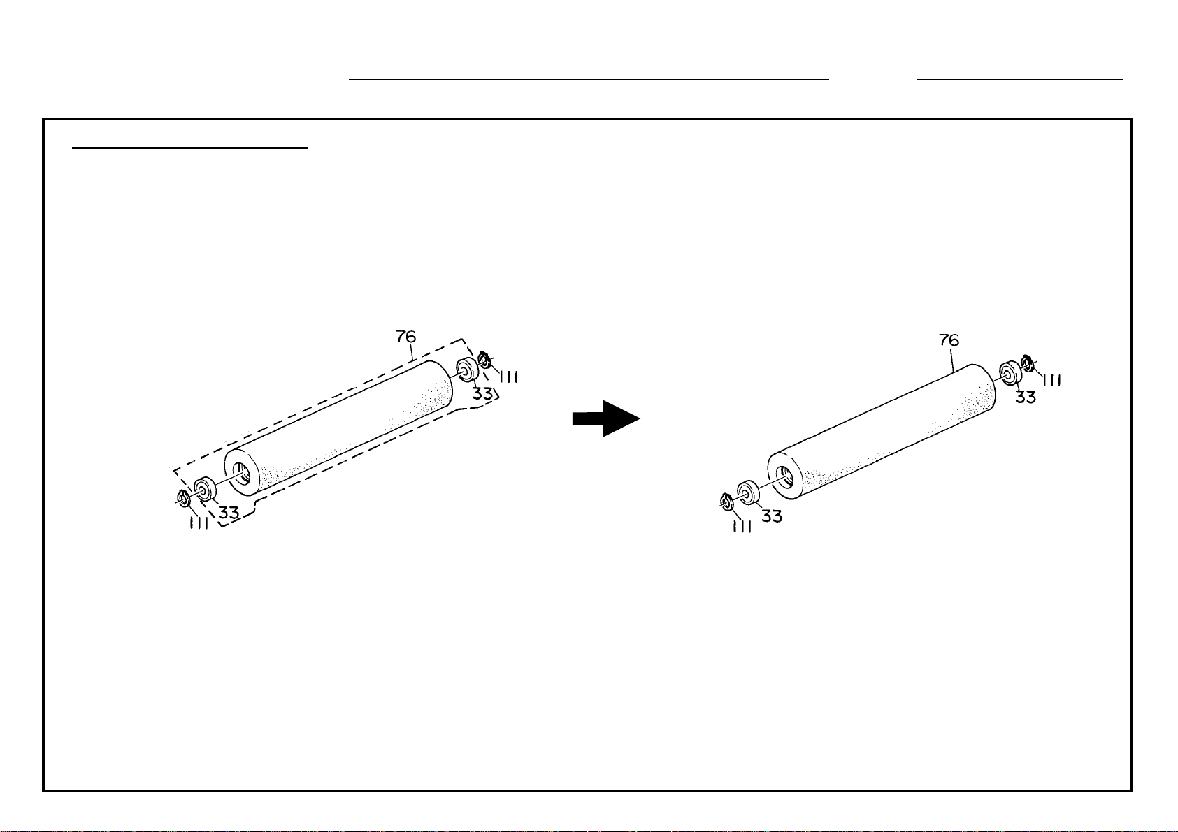
Please correct your parts catalog as follows:
MODIFICATION BULLETIN NO. 14 Page 2 of 3 ISSUED ON: Nov.30, ’90
Incorrect Illustration
In addition, the part number of the pressure roller has been changed due to vendor change.
Correct Illustration
T. Ito, Manager
Copier Technical Support
Page 14
MODIFICATION BULLETIN NO. 14 Page 3 of 3 ISSUED ON: Nov.30, ’90
MODEL NAME
NASHUA C240 115/60 USA, CANADA A030 - 16
RICOH NC100 115/60 USA, CANADA A030 - 17
RICOH NC100 110/60 TAIWAN A030 - 19
NASHUA C240 220, 240/50 EUROPE, etc. A030 - 25
INFOTEC 7125 220, 240/50 EUROPE A030 - 26
RICOH NC100 220, 240/50 EUROPE, etc. A030 - 27
RICOH NC100 220/50 ASIA A030 - 29
V/Hz DESTINATION CODE SERIAL NUMBER
Page 15
MODIFICATION BULLETIN NO. 15 Page 1 of 2 ISSUED ON: December 15, ’90
Model NC11 Volt/Hz
Modified Article Thermofuse
Reason for
As per field’s request
Modification
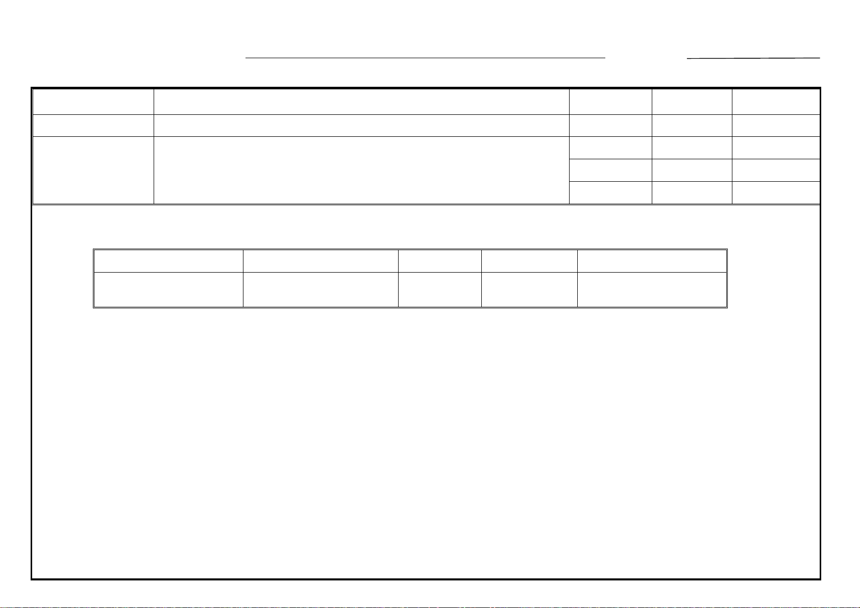
As per field request, the thermofuse on the exposure lamp unit has been registered as a
service part.
Part No. Description Q’ty Index No. Page
A0305379 Thermofuse - 128°C 1 * 49 1 - 33
09503005M Philips Screw with Lock Washer - M3 x 5 n + 2 * 115 1 - 33
* New Index No.
Date of
Modification
Serial Number
T. Ito, Manager
Copier Technical Support
Page 16
MODIFICATION BULLETIN NO. 15 Page 2 of 2 ISSUED ON: December 15, ’90
MODEL NAME
NASHUA C240 115/60 USA, CANADA A030 - 16
RICOH NC100 115/60 USA, CANADA A030 - 17
RICOH NC100 110/60 TAIWAN A030 - 19
NASHUA C240 220, 240/50 EUROPE, etc. A030 - 25
INFOTEC 7125 220, 240/50 EUROPE A030 - 26
RICOH NC100 220, 240/50 EUROPE, etc. A030 - 27
RICOH NC100 220/50 ASIA A030 - 29
V/Hz DESTINATION CODE SERIAL NUMBER
Page 17

MODIFICATION BULLETIN NO. 16 Page 1 of 3 ISSUED ON: December 15, ’90
Model NC11 Volt/Hz
Modified Article Toner Collection Bottle
Reason for
To provide instructions on the handling of the toner collection bottle
Modification
Draw
No.
Old Parts
No.
A0309505 A0309509 Toner Collection Bottle 1 - 1 X/O 32 1-51
New Parts
No.
AA000059 Caution Decal - English 0 - 1 *48 15
AA000060 Caution Decal - 4 Languages 0 - 1 *48 15
Description
Date of
Modification
A.B.C. Q’ty Used
Old →
Rank Part No. Description Index No. Page
New
Inter-
change-
ability
Part needed for replacement by new part Parts Catalog
* : New Index
Serial Number
Rank: A : Replace with new parts immediately. B : Replace with new parts at time of repair. C : Replace with new parts at time of overhall.
Interchangeability:
(1) When old and new parts are not mutually interchangeable, use additional parts or an assembly part as indicated in "Parts needed for replacement by new part" to
install the new part.
(2) The mark to the left of the slash indicates whether the old part can be used in the new machine, and the mark to the right indicates whether the new part can be used
in the old machine. x = Not interchangeable o = Interchangeable
Page 18
DETAILS OF MODIFICATION
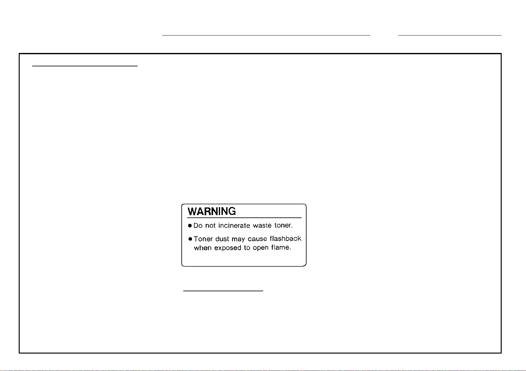
The decal shown below has been applied to the toner collection bottle to instruct customer
engineers on proper handling. Also, a 4 language decal set (German, French, Italian, and
Spanish) have been added to the new part to replace the English decal as occasion calls.
MODIFICATION BULLETIN NO. 16 Page 2 of 3 ISSUED ON: December 15, ’90
Caution Decal - English
T . Ito, Manager
Copier Technical Support
Page 19

MODIFICATION BULLETIN NO. 16 Page 3 of 3 ISSUED ON: December 15, ’90
MODEL NAME
NASHUA C240 115/60 USA, CANADA A030 - 16 186012XXXX
RICOH NC100 115/60 USA, CANADA A030 - 17 2520090001
RICOH NC100 110/60 TAIWAN A030 - 19 2520090144
NASHUA C240 220, 240/50 EUROPE, etc. A030 - 25 1850080001
INFOTEC 7125 220, 240/50 EUROPE A030 - 26 3910900001
RICOH NC100 220, 240/50 EUROPE, etc. A030 - 27 2520090149
RICOH NC100 220/50 ASIA A030 - 29 2520090478
V/Hz DESTINATION CODE SERIAL NUMBER
Page 20

MODIFICATION BULLETIN NO. 17 Page 1 of 4 ISSUED ON: Jan. 31, ’91
Model NC - 11 Volt/Hz
Modified Article Motor PCB, Process PCB, Charge Power Pack etc.
Reason for
Modification
Draw
No.
Old Parts
No.
[--25, --26, and --27]
1 A0305118 A0305613 Motor PCB - Europe 1 → 1 X/O 6 1-55
1 A0305184 A0305617 Process PCB - Europe 1 → 1 X/O 2 1-55
2 A0305897 Shielding Plate 1 → 0 (See NC - 11 M/B No.2) 37 1-55
3 A0305430 A0305425 Motor Control Harness 1 → 1 X/O 13 1-53
3 AZ320028 AZ320054 Charge Power Pack - Europe 1 → 1 X/O 12 1-55
To increase the tolerance for EMI (VDE) standard.
(Only for model codes: --25, --26, and --27)
New Parts
No.
Description
A.B.C. Q’ty Used
Old →
Rank Part No. Description Index No. Page
New
Inter-
change-
ability
Part needed for replacement by new part Parts Catalog
Date of
Modification
Serial Number
[--25 only]
4 A0307474 A0307471 Rear Cover Ass’y - Nashua 1 → 1 O/X 54 1-3
4 A0307475 A0307472 Rear Cover - Nashua 1 → 1 O/X (See NC - 11 M/B No.1, Page 2)) 37 1-3
Rank: A : Replace with new parts immediately. B : Replace with new parts at time of repair. C : Replace with new parts at time of overhall.
Interchangeability:
(1) When old and new parts are not mutually interchangeable, use additional parts or an assembly part as indicated in "Parts needed for replacement by new part" to
install the new part.
(2) The mark to the left of the slash indicates whether the old part can be used in the new machine, and the mark to the right indicates whether the new part can be used
in the old machine. x = Not interchangeable o = Interchangeable
Page 21
MODIFICATION BULLETIN NO. 17 Page 2 of 4 ISSUED ON: Jan. 31, ’91
Draw
No.
Old Parts
No.
[--26 only]
4 A0307671 A0307674 Rear Cover Ass’y - Infotec 1 → 1 O/X 54 1-3
4 A0307675 A0307672 Rear Cover - Infotec 1 → 1 O/X (See NC - 11 M/B No.1, Page 2) 37 1-3
[--27 only]
4 A0301303 A0301301 Rear Cover Ass’y - Ricoh 1 → 1 O/X 54 1-3
4 A0301304 A0301306 Rear Cover - Ricoh 1 → 1 O/X (See NC - 11 M/B No.1, Page 2) 37 1-3
New Parts
No.
Description
A.B.C. Q’ty Used
Old →
Rank Part No. Description Index No. Page
New
Inter-
change-
ability
Part needed for replacement by new part Parts Catalog
Page 22

DETAILS OF MODIFICATION
To increase the tolerance of electrolytic intensity for EMI (VDE) standard, the following modificati on has been
applied to European models such as --25, 26, and --27. (There is no change for other models.)
1. Motor PCB and Process PCB
The printed circuit pattern on these PCB’s is changed from single layer to multi-layer.
2. Shielding plate
The shielding plate used in European models is eliminated.
3. Motor control harness and change power pack
A ferrite core is added to:
1) the high voltage cable for PCC on the charge power pack
2) the motor control harness inbetween the main PCB and the 3 servo PCB.
MODIFICATION BULLETIN NO. 17 Page 3 of 4 ISSUED ON: Jan. 31, ’91
4. Rear Cover
The conductive painting layer inside the rear cover is elminated. As a result, the rear cover used in 115V models
is commonly used for European models, too.
T. Ito, Manager
Copier Technical Support
Page 23
MODIFICATION BULLETIN NO. 17 Page 4 of 4 ISSUED ON: Jan. 31, ’91
MODEL NAME
NASHUA C240 115/60 USA, CANADA A030 - 16
RICOH NC100 115/60 USA, CANADA A030 - 17
RICOH NC100 110/60 TAIWAN A030 - 19
NASHUA C240 220, 240/50 EUROPE, etc. A030 - 25 185101XXXX
INFOTEC 7125 220, 240/50 EUROPE A030 - 26 39101XXXXX
RICOH NC100 220, 240/50 EUROPE, etc. A030 - 27 2520120179
RICOH NC100 220/50 ASIA A030 - 29
V/Hz DESTINATION CODE SERIAL NUMBER
Page 24
MODIFICATION BULLETIN NO. 18 Page 1 of 1 ISSUED ON: Jan. 31, ’91
Model NC11 Volt/Hz
Modified Article Diode on the DC main harness
Reason for
Discontinuation of the old diode
Modification
Old P/N New P/N Q’ty Used Interchangeability P/C
14020423 (Diode S 5500G) 14021035 (Diode S 5688G) 1 → 1 O/O
Due to discontinuation of an old part, a new part is registered.
Date of
Modification
Page 1 - 69 #184
(See M/B No.1, Page 8)
Serial Number
T. Ito, Manager
Copier Technical Support
Page 25
MODIFICATION BULLETIN NO. 19 Page 1 of 5 ISSUED ON: July 15, ’91
Model NC - 11 Volt/Hz
Modified Article Ozone Filter
Reason for
Modification
Draw
No.
Old Parts
No.
1 AA010037 Ozone Filter - Fusing Exhaust Fan 1 → 0
2 AA010038 Ozone Filter - Transfer Exhaust Fan 1 → 0
3 AA010039 Ozone Filter - Development 2 → 0
1. Thickness change requested by vendor
2. Set parts number registration
New Parts
No.
AA010055 Ozone Filter - Fusing Exhaust Fan 0 → 2
AA010056 Ozone Filter - Transfer Exhaust Fan 0 → 2
AA010057 Ozone Filter - Development 0 → 3
Description
A.B.C.
Rank Part No. Description Index No. Page
Q’ty Used
Old → New
Date of
Modification
Inter-
change-
ability
O/O 38 1 - 3
O/O 33 1 - 3
O/O 11 1 - 57
Part needed for replacement by new part Parts Catalog
Serial Number
4 AA010055 Ozone Filter - Fusing Exhaust Fan 2 → 0
A0309517 Fusing Ozone Filter Set 0 → 1
5 AA010056 Ozone Filter - Transfer Exhaust Fan 2 → 0
A0309518 Transfer Ozone Filter Set 0 → 1
Rank: A : Replace with new parts immediately. B : Replace with new parts at time of repair. C : Replace with new parts at time of overhaul.
Interchangeability:
(1) When old and new parts are not mutually interchangeable, use additional parts or an assembly part as indicated in "Parts needed for replacement by new part" to
install the new part.
(2) The mark to the left of the slash indicates whether the old part can be used in the new machine, and the mark to the right indicates whether the new part can be used
in the old machine. x = Not interchangeable o = Interchangeable
O/O 38 1 - 3
O/O 33 1 - 3
Page 26

MODIFICATION BULLETIN NO. 19 Page 2 of 5 ISSUED ON: July 15, ’91
Draw
No.
Old Parts
No.
6 AA010057 Ozone Filter - Development 3 → 0
New Parts
No.
A0309519 Development Ozone Filter Set 0 → 1
Description
A.B.C.
Rank Part No. Description Index No. Page
Q’ty Used
Old → New
Inter-
change-
ability
O/O 11 1 - 57
Part needed for replacement by new part Parts Catalog
Page 27

DETAILS OF MODIFICATION
MODIFICATION BULLETIN NO. 19 Page 3 of 5 ISSUED ON: July 15, ’91
t = thickness
(Item No. 1 and 4)
Ozone filter for
fusing exhaust fan
(Item No. 2 and 5)
Ozone filter for
transfer exhaust
fan
(Item No. 3 and 6)
Ozone filter for
development
Note Don’t use these numbers for ordering
1. Item No. 1, 2 and 3
Due to the request from these parts vendor, the thickness of each
ozone filter has been changed. So, the necessary number of new
filters per machine has also been changed.
P/N AA010037
t = 30mm
1pce/machine
P/N AA010038
t = 30mm
1 pce/machine
P/N AA010039
t = 25mm
2 pcs/machine
O/O
O/O
O/O
(P/N AA010055)
2 pcs/machine
(P/N AA010056)
2 pcs/machine
(P/N AA010057)
t = 16.7mm
3 pcs/machine
2. Item No. 4, 5 and 6
Due to the parts number change explained at left, the necessary
number of filters per machine is packed and is registered as a set part
number.
P/N A0309517
P/N AA010055 x 2pcs/set
1 set/machine
P/N A0309518
P/N AA010056 x 2pcs/set
1 set/machine
P/N A0309519
P/N AA010057 x 3pcs/set
1 set/machine
t = 15mm
t = 15mm
O/O
O/O
O/O
Page 28

MODIFICATION BULLETIN NO. 19 Page 4 of 5 ISSUED ON: July 15, ’91
DETAILS OF MODIFICATION
Parts modification history for ozone filters
Ozone filters for NC11 have been changed two or three times. For your reference, the following is t he modification history: For your reference:
Ozone Filter - Fusing
Exhaust Fan
Ozone Filter - Transfer
Exhaust Fan
Ozone Filter - Development
Ozone Filter - Optics
P/N listed in the parts
catalog
P/N AA010029
t = 30mm
1pce/machine
P/N AA010030
t = 30mm
1pce/machine
P/N AA010031
t = 50mm
1 pce/machine
P/N AA010032
1pce/machine
O/O
M/B 1.
O/O
M/B 1.
O/O
M/B 1.
O/O
M/B 1.
M/B 1 : P/C correction
M/B 3 : Vendor change
1 2 (3)
AA010011
t = 30mm
1 pcs/machine
AA010012
t = 30mm
1 pce/machine
AA010016
t = 50mm
1pce/machine
AA010017
1pce/machine
O/O
M/B 3.
O/O
M/B 3.
O/O
M/B 3.
O/O
M/B 3.
AA010037
t = 30mm
1pce/machine
AA010038
t = 30mm
1pce/machine
AA010039 *
t = 25mm
2pcs/machine
AA010040
1pce/machine
O/O
M/B 19.
O/O
M/B 19.
O/O
M/B 19.
* : When using this part, please note that 2pcs are used for one machine.
(AA010055)
t = 15mm
2pcs/machine
(AA010056)
t = 15mm
2pcs/machine
(AA010057)
t = 16.7mm
3pcs/machine
O/O
M/B 19.
O/O
M/B 19.
O/O
M/B 19.
3
(Set Number)
A0309517
t = 15mm x 2pcs/set
1 set/machine
A0309518
t = 15mm x 2pcs/set
a set/machine
A0309519
t = 16.7mm x 3pcs/set
1set/machine
T. Ito, Manager
Copier Technical Support
Page 29

MODIFICATION BULLETIN NO. 19 Page 5 of 5 ISSUED ON: July 15, ’91
MODEL NAME
NASHUA C240 115/60 USA, CANADA A030 - 16 186105XXXX
RICOH NC100 115/60 USA, CANADA A030 - 17 252105XXXX
RICOH NC100 110/60 TAIWAN A030 - 19 252105XXXX
NASHUA C240 220, 240/50 EUROPE, etc. A030 - 25 1851040029
INFOTEC 7125 220, 240/50 EUROPE A030 - 26 39105XXXXX
RICOH NC100 220, 240/50 EUROPE, etc. A030 - 27 2521040001
RICOH NC100 220/50 ASIA A030 - 29 252105XXXX
V/Hz DESTINATION CODE SERIAL NUMBER
Page 30

MODIFICATION BULLETIN NO. 20 Page 1 of 4 ISSUED ON: July 15, ’91
Model NC11 Volt/Hz
Modified Article Drum Holder etc.
Reason for
To increase the strength of the rear side plate
Modification
Draw
No.
Old Parts
No.
A0302264 A0302267 Drum Holder 1 - 1 X/O 17 1 - 19
A0302266 A0302268 Rear Drum Bracket 1 - 1 X/X 21 1 - 19
A0303681 A0303683 Duct - Change Fan 1 - 1 X/X 14 1 - 51
New Parts
No.
A0301072 Support Plate 0 - 1 *27 1 - 57
04340080W Tapping Screw - M4x8 n → n+2 101 1 - 57
Description
Date of
Modification
A.B.C.
Rank Part No. Description Index No. Page
Q’ty Used
Old → New
Inter-
change-
ability
Part needed for replacement by new part Parts Catalog
* New Index No.
Serial Number
Rank: A : Replace with new parts immediately. B : Replace with new parts at time of repair. C : Replace with new parts at time of overhaul.
Interchangeability:
(1) When old and new parts are not mutually interchangeable, use additional parts or an assembly part as indicated in "Parts needed for replacement by new part" to
install the new part.
(2) The mark to the left of the slash indicates whether the old part can be used in the new machine, and the mark to the right indicates whether the new part can be used
in the old machine. x = Not interchangeable o = Interchangeable
Page 31

MODIFICATION BULLETIN NO. 20 Page 2 of 4 ISSUED ON: July 15, ’91
DETAILS OF MODIFICATION
To increase the strength of the rear side plate, the support plate [A] with two tapping screw - M4x8 [B] have been added
between the rear side plate [C] and the optics rear side plate [D]. These two rear side plates have been changed, but they are
not the service parts. To ensure correct mounting of the OPC drum motor, the shape of the hook and the screw hole of the rear
drum bracket have been changed. A similar change has been made on the drum holder shown next page.
Rear drum bracket
[D]
[A]
[C]
Front rear side view
[B]
Old
New
Page 32

MODIFICATION BULLETIN NO. 20 Page 3 of 4 ISSUED ON: July 15, ’91
DETAILS OF MODIFICATION
Due to this modification, the shape of the duct-charge fan has been changed as follows:
Duct - charge fan
Old
Old
New
Drum holder
81.72mm
Old
81.59mm
New
T. Ito, Manager
Copier Technical Support
Page 33

MODIFICATION BULLETIN NO. 20 Page 4 of 4 ISSUED ON: July 15, ’91
MODEL NAME
NASHUA C240 115/60 USA, CANADA A030 - 16 186107XXXX
RICOH NC100 115/60 USA, CANADA A030 - 17 2521050001
RICOH NC100 110/60 TAIWAN A030 - 19 2521050003
NASHUA C240 220, 240/50 EUROPE, etc. A030 - 25 1851040001
INFOTEC 7125 220, 240/50 EUROPE A030 - 26 391071XXXX
RICOH NC100 220, 240/50 EUROPE, etc. A030 - 27 2521040001
RICOH NC100 220/50 ASIA A030 - 29 252107XXXX
V/Hz DESTINATION CODE SERIAL NUMBER
Page 34

Reissued on : June 30, ’92
MODIFICATION BULLETIN NO. 21 Page 1 of 3 ISSUED ON: July 15, ’91
Model
Modified Article
Reason for
Modification
Draw
No.
Old Parts
A0305241 A0305246 Erase Lamp 1 - 1 O/O
A0302280 A0302275
No.
NC11
Drum Stay and Erase Lamp
To facilitate servicing
New Parts
No.
A0722101
09524006W
Drum Stay
Erase Lamp Holder
Screw - M4 x 6
Description
Volt/Hz
A.B.C.
Rank Part No. Description Index No. Page
Q’ty Used
Old → New
1 - 1 O/O 1 1-19
0 → 1 58 1-19
n → n+1 119 1-19
Inter-
change-
ability
Part needed for replacement by new part Parts Catalog
* See note
Date of
Modification
Serial Number
38 1-19
Rank: A : Replace with new parts immediately. B : Replace with new parts at time of repair. C : Replace with new parts at time of overhaul.
Interchangeability:
(1) When old and new parts are not mutually interchangeable, use additional parts or an assembly part as indicated in "Parts needed for replacement by new part" to
install the new part.
(2) The mark to the left of the slash indicates whether the old part can be used in the new machine, and the mark to the right indicates whether the new part can be used
in the old machine. x = Not interchangeable o = Interchangeable
Page 35

Reissued on : June 30, ’92
MODIFICATION BULLETIN NO. 21 Page 2 of 3 ISSUED ON: July 15, ’91
DETAILS OF MODIFICATION
To facilitate servicing, the shape of the drum stay and the erase lamp have been changed as shown in the figure below:
The erase lamp holder has been added to the new drum stay. With new drum stay and erase lamp holder it becomes possible to
remove the erase lamp by removing the erase lamp holder (1 screw). (With the old drum stay, it is n ecessary to remove the drum stay (3
screws) before removing the erase lamp.)
Drum Stay
Old
New
Erase Lamp
Old
Erase Lamp Holder
Note : For some combinations of old and new Erase Lamp and Drum Stay there are some notices.
Old Erase Lamp New Erase Lamp
Old Drum Stay No notice No notice
New Drum Stay
Erase Lamp Holder can not be installed due
to shape of erase lamp. Instead of installing
the holder, please be sure to confirm the
Erase Lamp being set securely.
The best way is to install Drum Stay with Erase Lamp
Holder (1 screw). If Erase Lamp Holder is not available
immediately, install only the Drum Stay. In this case, please
be sure to confirm the Erase Lamp being set securely.
New
T. Ito, Manager
Copier Technical Support
Page 36

Reissued on : June 30, ’92
MODIFICATION BULLETIN NO. 21 Page 3 of 3 ISSUED ON: July 15, ’91
MODEL NAME
NASHUA C240 115/60 USA, CANADA A030 - 16 186107XXXX
RICOH NC100 115/60 USA, CANADA A030 - 17 252107XXXX
RICOH NC100 110/60 TAIWAN A030 - 19 252107XXXX
NASHUA C240 220, 240/50 EUROPE, etc. A030 - 25 1851060001
INFOTEC 7125 220, 240/50 EUROPE A030 - 26 391071XXXX
RICOH NC100 220, 240/50 EUROPE, etc. A030 - 27 2521050046
RICOH NC100 220/50 ASIA A030 - 29 252107XXXX
V/Hz DESTINATION CODE SERIAL NUMBER
Page 37

Reissued on: December 15, ’91
2nd Reissued on: January 31, ’92
MODIFICATION BULLETIN NO. 22 Page 1 of 2 ISSUED ON: November 15, ’91
Model NC11 (Excluding Ricoh USA and Taiwan versions) Volt/Hz
Modified Article Fusing Cover
Reason for
Due to parts standardization with other model
Modification
Old P/N New P/N Q’ty Used Interchangeability
Index No. Page
A0304055 A0304060 1 → 1 O/O 3 1 - 47
Due to parts standardization with other model, the shape of the fusing cover has been changed as fol lows:
Parts Catalog
Date of
Modification
Serial Number
Old
New
T. Ito, Manager
Copier Technical Support
Page 38

Reissued on: December 15, ’91
2nd Reissued on: January 31, ’92
MODIFICATION BULLETIN NO. 22 Page 2 of 2 ISSUED ON: November 15, ’91
MODEL NAME
NASHUA C240 115/60 USA, CANADA A030 - 16
RICOH NC100 115/60 USA, CANADA A030 - 17
RICOH NC100 110/60 TAIWAN A030 - 19
NASHUA C240 220, 240/50 EUROPE, etc. A030 - 25
INFOTEC 7125 220, 240/50 EUROPE A030 - 26
RICOH NC100 220, 240/50 EUROPE, etc. A030 - 27
RICOH NC100 220/50 ASIA A030 - 29
V/Hz DESTINATION CODE SERIAL NUMBER
Page 39

MODIFICATION BULLETIN NO. 23 Page 1 of 2 ISSUED ON: November 15, ’91
Model NC11 Volt/Hz
Modified Article 3 Service Control Board
Reason for
To increase reliability of 3 servomotor control board
Modification
Old P/N New P/N Q’ty Used Interchangeability
Index No. Page
A0305132 A0305133 1 → 1 O/O 11 1 - 53
To increase reliability (color alignment) of the 3 servomotor control board, the four electronic com ponent parts
(not service part ) on this board have been changed, The interchangeability code is O/O.
Parts Catalog
Date of
Modification
Serial Number
T. Ito, Manager
Copier Technical Support
Page 40

MODIFICATION BULLETIN NO. 23 Page 2 of 2 ISSUED ON: November 15, ’91
MODEL NAME
NASHUA C240 115/60 USA, CANADA A030 - 16
RICOH NC100 115/60 USA, CANADA A030 - 17
RICOH NC100 110/60 TAIWAN A030 - 19
NASHUA C240 220, 240/50 EUROPE, etc. A030 - 25
INFOTEC 7125 220, 240/50 EUROPE A030 - 26
RICOH NC100 220, 240/50 EUROPE, etc. A030 - 27
RICOH NC100 220/50 ASIA A030 - 29
V/Hz DESTINATION CODE SERIAL NUMBER
Page 41

MODIFICATION BULLETIN NO. 24 Page 1 of 3 ISSUED ON: November 30, ’91
Model NC11 Volt/Hz
Modified Article 3 Servomotor Control Board
Reason for
To increase reliability of 3 servomotor control board
Modification
Draw
No.
Old Parts
No.
A0305133 A0305130 3 Servomotor Control Board 1 → 1 O/O 11 1 - 53
A0305136 EP ROM - 3 Servo Motors Board
New Parts
No.
A0305137 IC - TMM27256AD - 15 1 → 1 O/O 4 1 - 53
Description
Date of
Modification
A.B.C.
Rank Part No. Description Index No. Page
Q’ty Used
Old → New
Inter-
change-
ability
Part needed for replacement by new part Parts Catalog
Serial Number
Rank: A : Replace with new parts immediately. B : Replace with new parts at time of repair. C : Replace with new parts at time of overhaul.
Interchangeability:
(1) When old and new parts are not mutually interchangeable, use additional parts or an assembly part as indicated in "Parts needed for replacement by new part" to
install the new part.
(2) The mark to the left of the slash indicates whether the old part can be used in the new machine, and the mark to the right indicates whether the new part can be used
in the old machine. x = Not interchangeable o = Interchangeable
Page 42

DETAILS OF MODIFICATION
When the machine is in the stand by condition, the current is output constantly to the IC on the 3 s ervomotor
control board to keep the home position of the transfer drum, and the IC generates heat. (The funct ion of
this IC is driving the transfer drum.)
To improve IC’s durability, the software program has been changed. In the stand by condition, the c urrent
out put to the IC has been reduced to decrease heat at the IC.
MODIFICATION BULLETIN NO. 24 Page 2 of 3 ISSUED ON: November 30, ’91
T. Ito, Manager
Copier Technical Support
Page 43

MODIFICATION BULLETIN NO. 24 Page 3 of 3 ISSUED ON: November 30, ’91
MODEL NAME
NASHUA C240 115/60 USA, CANADA A030 - 16 186110XXXX
RICOH NC100 115/60 USA, CANADA A030 - 17 252110XXXX
RICOH NC100 110/60 TAIWAN A030 - 19 2521090001
NASHUA C240 220, 240/50 EUROPE, etc. A030 - 25 1851080004
INFOTEC 7125 220, 240/50 EUROPE A030 - 26 391101XXXX
RICOH NC100 220, 240/50 EUROPE, etc. A030 - 27 2521070001
RICOH NC100 220/50 ASIA A030 - 29 252110XXXX
V/Hz DESTINATION CODE SERIAL NUMBER
Page 44

MODIFICATION BULLETIN NO. 25 Page 1 of 4 ISSUED ON: January 31, ’92
Model NC11 Volt/Hz
Modified Article See below
Reason for
Due to parts standardization with other model
Modification
Date of
Modification
Due to parts standardization with other model, the following parts has been changed.
Old P/N New P/N Q’ty Interchangeability Description
AA140232 AA140419 1 O/O Shaft - Support Roller Bracket 27 41 All
AA145091 AA145160 1 O/O Shaft - Pick-off Lever 25 29 All
AA150187 AA151590 3 O/O Seal - 12 X95 43 17 All
AB013312 AB013523 1 O/O Gear - 32Z 17 8 All
AD031165 AD031218 1 O/O Development Roller - YELLOW 43 23 All
Parts Catalog
Destination
Index No. Page
Serial Number
AW230001 AW230005 1 O/O CYAN Toner Density Sensor 43 8 All
AW230002 AW230005 1 O/O MAGENTA Toner Density Sensor 43 12 All
AW230003 AW230005 1 O/O YELLOW Toner Density Sensor 43 25 All
A0301085 A0721085 1 O/O Bracket - Paper Feed Motor 17 2 All
A0301669 A0721671 1 O/O Scale Mounting Bracket 33 11 All
A0301674 A0721100 1 O/O Platen Cover Bracket - Left 33 25 All
A0301675 A0721837 1 O/O Platen Cover Bracket - Right 33 15 All
A0301831 A0721831 1 O/O Scanner Motor Bracket 33 17 All
A0301900 A0721841 1 O/O 2nd Scanner Slider 33 40 All
Page 45

MODIFICATION BULLETIN NO. 25 Page 2 of 4 ISSUED ON: January 31, ’92
Old P/N New P/N Q’ty Interchangeability Description
A0302630 A0722645 1 O/O
A0302671 A0722671 1 O/O Paper Feed Guide - Middle 17 49 All
A0302687 A0722667 1 O/O Paper Feed Guide - Lower 17 38 All
A0302701 A0722702 1 O/O Paper Relay Guide - Lower 17 53 All
A0302711 A0722611 2 O/O Paper Feed Stay 11 32 All
A0302855 A0722701 2 O/O Pick-up Guide 9 3 All
A0302921 A0722703 1 O/O Front Cassette Holder 9 40 Ricoh version only
A0302925 A0722706 1 O/O Rear Cassette Holder 9 2 Ricoh version only
A0303252 A0723252 1 O/O
A0303260 A0723260 1 O/O
A0303263 A0723263 3 O/O Spacer - Toner Density Sensor 43 7 All
A0303337 A0723337 3 O/O Adjuster - Development Roller 43 44 All
Registration Guide - 3rd Paper
Feed
Front Side Plate - Color
Development
Rear Side Plate - Color
Development
Parts Catalog
Destination
Index No. Page
15 25 All
43 42 All
43 22 All
A0303430 A0723430 1 O/O Connector Bracket - Color Dev. 51 39 All
A0304084 A0724084 1 O/O Entrance Guide Plate - Lower 47 53 All
A0304089 A0724089 1 O/O Right Fusing Rail 47 46 All
A0304090 A0724090 1 O/O Upper Frame 47 9 All
A0305889 A0721120 1 O/O Cooling Fan Bracket 53 20 All
A0306059 A0726059 1 O/O Mylar Seal - Transfer Drum 23 24 All
A0306104 A0726104 1 O/O Front Side Plate 25 60 All
A0306128 A0726128 1 O/O Shaft - Transfer Drum Stripper 25 4 All
Page 46

MODIFICATION BULLETIN NO. 25 Page 3 of 4 ISSUED ON: January 31, ’92
Old P/N New P/N Q’ty Interchangeability Description
A0306220 A0726220 1 O/O Bracket - Lock Release Lever 25 39 All
A0306227 A0726227 1 O/O Release Lever Link 25 79 All
A0304462 A0724462 1 O/O Upper Exit Guide 49 4 All
A0306399 A0726399 1 O/O Base Plate - T/D Cleaning 31 6 All
A0306433 A0726433 1 O/O
A0301694 A0721864 1 O/O Guide - Exposure Lamp Harness 33 36 All
A0306340 A0726340 1 O/O Rail - DC Discharge Unit 17 29 All
A0306345 A0726345 1 O/O Rail - AC Discharge Unit 17 30 All
A0082734 A0602950 1 O/O Large Cassette Cover 5 1 Ricoh version only
A0082737 A0602955 2 O/O Small Cassette Cover 5 1 Ricoh version only
52156436 52156674 2 O/O Small Cassette Cover 5 1 NSA/ Infotec version only
52156445 52156675 1 O/O Large Cassette Cover 5 1 NSA/ Infotec version only
Grounding Plate - Cleaning
Brush
Parts Catalog
Destination
Index No. Page
31 10 All
T. Ito, Manager
Copier Technical Support
Page 47

MODIFICATION BULLETIN NO. 25 Page 4 of 4 ISSUED ON: January 31, ’92
MODEL NAME
NASHUA C240 115/60 USA, CANADA A030 - 16
RICOH NC100 115/60 USA, CANADA A030 - 17
RICOH NC100 110/60 TAIWAN A030 - 19
NASHUA C240 220, 240/50 EUROPE, etc. A030 - 25
INFOTEC 7125 220, 240/50 EUROPE A030 - 26
RICOH NC100 220, 240/50 EUROPE, etc. A030 - 27
RICOH NC100 220/50 ASIA A030 - 29
V/Hz DESTINATION CODE SERIAL NUMBER
Page 48

Reissued on: March 15, ’92
MODIFICATION BULLETIN NO. 26 Page 1 of 2 ISSUED ON: February 15, ’92
Model NC11 Volt/Hz
Modified Article See below
Reason for
Modification
Due to parts standardization with other model / To improve the strength of the exposure
glass
Due to parts standardization with other model, Cover-Exposure Lamp Unit has been changed.
To improve the strength of the exposure glass, Exposure Glass has been changed.
Old P/N New P/N Q’ty Interchangeability Description
A0301632 A0301863 1 → 1 X/X Cover - Exposure Lamp Unit 2 1 - 33
A0301862 0 → 1 X/X O/O as a set Lamp Cover Angle * 50 1 - 33
03130050W 0 → 1 X/X Philips Pan Head Screw - M3 X 5 * 116 1 - 33
AC012019 AC012039 1 → 1 X/O Exposure Glass 12 1 - 33
Cover - Exposure
Lamp Unit
Old P/N A0301632
Cover - Exposure
Lamp Unit
New P/N A0301863
Philips Pan Head
Screw - M3 X 5
P/N 03130050W
Parts Catalog
Index No. Page
Exposure Glass
Old P/N AC012019
New P/N AC012039
Date of
Modification
*New Index
Serial Number
Lamp Cover
Angle
P/N A0301862
T. Ito, Manager
Copier Technical Support
Page 49

Reissued on: March 15, ’92
MODIFICATION BULLETIN NO. 26 Page 2 of 2 ISSUED ON: February 15, ’92
MODEL NAME
NASHUA C240 115/60 USA, CANADA A030 - 16 186109XXXX
RICOH NC100 115/60 USA, CANADA A030 - 17 252109XXXX
RICOH NC100 110/60 TAIWAN A030 - 19 2521090001
NASHUA C240 220, 240/50 EUROPE, etc. A030 - 25 185108XXXX
INFOTEC 7125 220, 240/50 EUROPE A030 - 26 391091XXXX
RICOH NC100 220, 240/50 EUROPE, etc. A030 - 27 2521070001
RICOH NC100 220/50 ASIA A030 - 29 252109XXXX
V/Hz DESTINATION CODE SERIAL NUMBER
Page 50

Reissued on: April 15, ’92
MODIFICATION BULLETIN NO. 27 Page 1 of 2 ISSUED ON: February 29, ’92
Model NC11 Volt/Hz
Modified Article Paddle Roller
Reason for
To prevent toner from entering the gap between mixing auger and dual mixing paddle.
Modification
Date of
Modification
To prevent toner from entering the gap between mixing auger and dual mixing paddle (at the rear side of the machine),
Paddle Roller has been modified.
Old P/N New P/N Description Q’ty Interchangeability
AD038029 AD038046 Paddle Roller
4 → 4
X/O
Index No. Page
Parts Catalog
43
5
1 - 39
1 - 43
* Toner is carried to rear side by mixing auger. To
Rear Side
dual mixing paddle
reduce toner pressure around the rear inner end of dual
mixing paddle, distance A of mixing auger has been
increased from 42mm to 46mm.
Serial Number
mixing auger
Paddle Roller
Old P/N AD038029 New P/N AD038046
A
T. Ito, Manager
Copier Technical Support
Page 51

Reissued on: April 15, ’92
MODIFICATION BULLETIN NO. 27 Page 2 of 2 ISSUED ON: February 29, ’92
MODEL NAME
NASHUA C240 115/60 USA, CANADA A030 - 16 186109XXXX
RICOH NC100 115/60 USA, CANADA A030 - 17 252109XXXX
RICOH NC100 110/60 TAIWAN A030 - 19 2521090001
NASHUA C240 220, 240/50 EUROPE, etc. A030 - 25 1851080001
INFOTEC 7125 220, 240/50 EUROPE A030 - 26 391091XXXX
RICOH NC100 220, 240/50 EUROPE, etc. A030 - 27 2521070001
RICOH NC100 220/50 ASIA A030 - 29 252109XXXX
V/Hz DESTINATION CODE SERIAL NUMBER
Page 52

MODIFICATION BULLETIN NO. 28 Page 1 of 2 ISSUED ON: February 29, ’92
Model NC11 Volt/Hz
Modified Article Cleaning Unit
Reason for
Due to vendor change
Modification
Old P/N New P/N Q’ty Interchangeability
Index No. Page
A0303550 A0303551 1 → 1 O/O * 1 - 45
Due to vendor change, part number of cleaning unit has been changed.
Parts Catalog
Date of
Modification
Serial Number
T. Ito, Manager
Copier Technical Support
Page 53

MODIFICATION BULLETIN NO. 28 Page 2 of 2 ISSUED ON: February 29, ’92
MODEL NAME
NASHUA C240 115/60 USA, CANADA A030 - 16
RICOH NC100 115/60 USA, CANADA A030 - 17
RICOH NC100 110/60 TAIWAN A030 - 19
NASHUA C240 220, 240/50 EUROPE, etc. A030 - 25
INFOTEC 7125 220, 240/50 EUROPE A030 - 26
RICOH NC100 220, 240/50 EUROPE, etc. A030 - 27
RICOH NC100 220/50 ASIA A030 - 29
V/Hz DESTINATION CODE SERIAL NUMBER
Page 54

Reissued on: April 15, ’92
MODIFICATION BULLETIN NO. 29 Page 1 of 2 ISSUED ON: February 15, ’92
Model NC11 Volt/Hz
Modified Article Sleeve - Oil Pump
Reason for
To improve unflamability of the oil pump sleeve
Modification
Parts Catalog
Old P/N New P/N Q’ty Used Interchangeability
Index No. Page
AA180007 AA180035
1 → 1
X/O 67 1 - 47
To improve unflamability of the oil pump sleeve, its material has been changed.
67
60
61
68
59
60
61
62
Sleeve - Oil Pump
Old P/N AA180007
Date of
Modification
105
Serial Number
New P/N AA180035
69
70
T. Ito, Manager
Copier Technical Support
Page 55

Reissued on: April 15, ’92
MODIFICATION BULLETIN NO. 29 Page 2 of 2 ISSUED ON: February 15, ’92
MODEL NAME
NASHUA C240 115/60 USA, CANADA A030 - 16 186111XXXX
RICOH NC100 115/60 USA, CANADA A030 - 17 252111XXXX
RICOH NC100 110/60 TAIWAN A030 - 19 252111XXXX
NASHUA C240 220, 240/50 EUROPE, etc. A030 - 25 1851100001
INFOTEC 7125 220, 240/50 EUROPE A030 - 26 391111XXXX
RICOH NC100 220, 240/50 EUROPE, etc. A030 - 27 2521100001
RICOH NC100 220/50 ASIA A030 - 29 252111XXXX
V/Hz DESTINATION CODE SERIAL NUMBER
Page 56

MODIFICATION BULLETIN NO. 30 Page 1 of 3 ISSUED ON: March 15, ’92
Model NC11 Volt/Hz
Modified Article See below
Reason for
Modification
Draw
No.
Old Parts
No.
AA040011 AA040018 Transport Belt 1 → 1 O/O 26 17
A0301360 A0721360 Left Inner Cover - Small 1 → 1 O/O 35 17
A0306350 A0306335 Separation Corona Unit 1 → 1 O/O 1 21
A0303858 A0723852 Transport Guide Plate - Rear 1 → 1 X/X 23 17
A0303853 Fixed Plate - Vacuum Fan 1 → 0 22 17
09524006W Screw M4 x 6 2 → 0 104 17
Due to parts standardization with other model
New Parts
No.
Description
Date of
Modification
A.B.C.
Rank Part No. Description Index No. Page
Q’ty Used
Old → New
Inter-
change-
ability
Part needed for replacement by new part Parts Catalog
Serial Number
A0723889 Right Fan Stopper 0 → 1 X/X O/O as a set * 54 17
A0723890 Left Fan Stopper 0 → 1 X/X * 55 17
A0723870 Fan Bracket 0 → 1 X/X * 56 17
04140082W
Rank: A : Replace with new parts immediately. B : Replace with new parts at time of repair. C : Replace with new parts at time of overhaul.
Interchangeability:
(1) When old and new parts are not mutually interchangeable, use additional parts or an assembly part as indicated in "Parts needed for replacement by new part" to
install the new part.
(2) The mark to the left of the slash indicates whether the old part can be used in the new machine, and the mark to the right indicates whether the new part can be used
in the old machine. x = Not interchangeable o = Interchangeable
Tapping Screw With Flat
Washer - M4
0 → 2 X/X * New Index * 119 17
Page 57

DETAILS OF MODIFICATION
MODIFICATION BULLETIN NO. 30 Page 2 of 3 ISSUED ON: March 15, ’92
P/N A0303858
Transport Guide Plate - Rear
P/N A0303853
Fixed Plate
- Vacuum Fan
P/N 09524006W
Screw M4 x 6
P/N A0723852
Transport Guide Plate - Rear
P/N A0723870
Fan Bracket
P/N A0723890
Left Fan Stopper
P/N A0723889
Right Fan Stopper
P/N 04140082W
Tapping Screw With
Flat Washer - M4
Note: Interchangeability between A0303858 and A0723852 is X/X because the position of the
screw holes receiving the screws (09524006W for A0303858 and 04140082W for
A0723852) have been changed.
T. Ito, Manager
Copier Technical Support
Page 58

MODIFICATION BULLETIN NO. 30 Page 3 of 3 ISSUED ON: March 15, ’92
MODEL NAME
NASHUA C240 115/60 USA, CANADA A030 - 16 186111XXXX
RICOH NC100 115/60 USA, CANADA A030 - 17 252111XXXX
RICOH NC100 110/60 TAIWAN A030 - 19 252111XXXX
NASHUA C240 220, 240/50 EUROPE, etc. A030 - 25 1851100001
INFOTEC 7125 220, 240/50 EUROPE A030 - 26 391111XXXX
RICOH NC100 220, 240/50 EUROPE, etc. A030 - 27 2521100001
RICOH NC100 220/50 ASIA A030 - 29 252111XXXX
V/Hz DESTINATION CODE SERIAL NUMBER
Page 59

MODIFICATION BULLETIN NO. 31 Page 1 of 2 ISSUED ON: March 15, ’92
Model NC11 Volt/Hz
Modified Article Paddle Roller
Reason for
To improve toner sealing at the gap between mixing auger and dual mixing paddle.
Modification
Modification
To improve toner sealing at the gap between mixing auger and dual mixing paddle (at the rear side of the machine),
Paddle Roller has been modified.
Old P/N New P/N Description Q’ty Interchangeability
Index No. Page
AD038046 AD038051 Paddle Roller 4 → 4 X/O
Parts Catalog
43
5
1 - 39
1 - 43
* Toner is carried to rear side by mixing auger. To
Rear Side
dual mixing paddle
reduce toner pressure around the rear inner end
of dual mixing paddle, distance A of mixing
auger has been increased from 46mm to 58mm.
Date of
Serial Number
mixing auger
Paddle Roller
Old P/N AD038046 New P/N AD038051
A
T. Ito, Manager
Copier Technical Support
Page 60

MODIFICATION BULLETIN NO. 31 Page 2 of 2 ISSUED ON: March 15, ’92
MODEL NAME
NASHUA C240 115/60 USA, CANADA A030 - 16 186201XXXX
RICOH NC100 115/60 USA, CANADA A030 - 17 252201XXXX
RICOH NC100 110/60 TAIWAN A030 - 19 252201XXXX
NASHUA C240 220, 240/50 EUROPE, etc. A030 - 25 185201XXXX
INFOTEC 7125 220, 240/50 EUROPE A030 - 26 391012XXXX
RICOH NC100 220, 240/50 EUROPE, etc. A030 - 27 252201XXXX
RICOH NC100 220/50 ASIA A030 - 29 252201XXXX
V/Hz DESTINATION CODE SERIAL NUMBER
Page 61

MODIFICATION BULLETIN NO. 32 Page 1 of 4 ISSUED ON: March 15, ’92
Model NC11 Volt/Hz
Modified Article See below
Reason for
Due to parts standardization with other model
Modification
Date of
Modification
Due to parts standardization with other model, the following parts have been modified.
Old P/N New P/N Description Q’ty Interchangeability
AD021044 A0723724
AD021028 A0722005
A0306231 A0726231 Corona Wire Ring 6 → 6 O/O
A0306335 A0306375 Separation Corona Unit 1 → 1 O/O 1 1 - 21
Receptacle Housing PCC
Receptacle Housing Charge Corona
1 → 1 O/O 27 1 - 19
1 → 1 O/O 28 1 - 19
Index No. Page
Parts Catalog
45
7
11
Serial Number
1 - 19
1 - 21
1 - 27
AD022136 AD022241 Cover - Front End Block 3 → 3 O/O 2 1 - 21
AD022138 AD022243 Cover - Rear End Block 2 → 2 O/O 4 1 - 21
AD022188 AD022244 Front End Block 3 → 3 O/O 9 1 - 21
AD022137 AD022242 Rear End Block 2 → 2 O/O 12 1 - 21
A0306355 A0726355
A0306360 A0726360
AD024017 AD024028 Adjusting Screw 1 → 1 O/O 21 1 - 21
DC Discharge Unit Outer
AC Discharge Unit Outer
1 → 1 O/O 14 1 - 21
1 → 1 O/O 18 1 - 21
Page 62

DETAILS OF MODIFICATION
MODIFICATION BULLETIN NO. 32 Page 2 of 4 ISSUED ON: March 15, ’92
Old P/N New P/N Description Q’ty Interchangeability
Index No. Page
AD022148 AD022253 Cover - Rear End Block 1 → 1 O/O 22 1 - 21
AD022147 AD022254 Rear End Block - D. AC Outer 1 → 1 O/O 23 1 - 21
A0306215 A0306237 Cleaner Motor Cover 1 → 1 O/O 27 1 - 21
A0306216 A0726216 Holder - Transfer Corona Wire 1 → 1 O/O 37 1 - 21
A0306218 A0726218 Adjusting Plate 1 → 1 O/O 38 1 - 21
A0306217 A0726217 Adjusting Screw 1 → 1 O/O 39 1 - 21
AD022164 AD022258 Cover - Rear End Block 1 → 1 O/O 47 1 - 21
AD022163 AD022259 Rear End Block - Transfer Corona 1 → 1 O/O 48 1 - 21
AD022132 AD022245 Cover - Front End Block 1 → 1 O/O 2 1 - 27
AD022131 AD022246 Front End Block - Discharge 1 → 1 O/O 6 1 - 27
AD022134 AD022247 Cover - Rear End Block 1 → 1 O/O 10 1 - 27
AD022133 AD022248 Rear End Block 1 → 1 O/O 12 1 - 27
AD022049 AD024029 Adjusting Screw 2 → 2 O/O 13 1 - 27
A0306235 A0726235 AC Discharge Unit - Inner 1 → 1 O/O
Parts Catalog
14
3
1 - 27
1 - 29
AD022151 AD022252 Rear End Block - D. AC Inner 1 → 1 O/O 15 1 - 27
AD022152 AD022251 Cover - Rear End Block 1 → 1 O/O 16 1 - 27
Page 63

DETAILS OF MODIFICATION
MODIFICATION BULLETIN NO. 32 Page 3 of 4 ISSUED ON: March 15, ’92
Old P/N New P/N Description Q’ty Interchangeability
Index No. Page
AD022149 AD022250 Front End Block D. AC Inner 1 → 1 O/O 18 1 - 27
A0306095 A0726099 Receptacle - D. DC 1 → 1 O/O 20 1 - 27
A0306100 A0726106 Receptacle - D. AC 1 → 1 O/O 21 1 - 27
A0306090 A0726091 Receptacle - Transfer Corona 1 → 1 O/O 22 1 - 27
AD022150 AD022249 Cover - Front End Block 1 → 1 O/O 35 1 - 27
AD022123 A0723720 Front End Block - PCC 1 → 1 O/O 22 1 - 45
AD022124 A0723721 Front End Block Cover - PCC 1 → 1 O/O 24 1 - 45
AD022125 A0723722 Rear End Block - PCC 1 → 1 O/O 42 1 - 45
AD022126 A0723723 Rear End Block Cover - PCC 1 → 1 O/O 43 1 - 45
AD021034 A0726110 Receptacle Housing - Discharge 3 → 3 O/O 29 1 - 55
Parts Catalog
T. Ito, Manager
Copier Technical Support
Page 64

MODIFICATION BULLETIN NO. 32 Page 4 of 4 ISSUED ON: March 15, ’92
MODEL NAME
NASHUA C240 115/60 USA, CANADA A030 - 16
RICOH NC100 115/60 USA, CANADA A030 - 17
RICOH NC100 110/60 TAIWAN A030 - 19
NASHUA C240 220, 240/50 EUROPE, etc. A030 - 25
INFOTEC 7125 220, 240/50 EUROPE A030 - 26
RICOH NC100 220, 240/50 EUROPE, etc. A030 - 27
RICOH NC100 220/50 ASIA A030 - 29
V/Hz DESTINATION CODE SERIAL NUMBER
Page 65

MODIFICATION BULLETIN NO. 33 Page 1 of 2 ISSUED ON: May 31, ’92
Model
Modified Article
Reason for
Modification
NC - 11
Cover - Upper Relay Roller
To improve the reliability of the pick-off sensor
Volt/Hz
To improve the reliability of the pick-off sensor, a black mylar is added on the cover-upper relay r oller (A0302658).
Old P/N New P/N Description Q’ty Used
------- A0726344
Shielding Mylar
0 → 1
E
D
C
A
Index No. Page
# 57 (New) 1 - 17
New P/N A0726344
Shielding Mylar
Parts Catalog
* The edge "A" of the mylar is aligned with edge "B" of
cover-upper relay roller.
* * The distance "C" (between the edge "D" of
cover-upper relay roller and the edge "E" of the mylar)
is 96 ± 2mm.
Date of
Modification
Serial Number
B
P/N A0302658
Cover - upper relay roller
T. Ito, Manager
Copier Technical Support
Page 66

MODIFICATION BULLETIN NO. 33 Page 2 of 2 ISSUED ON: May 31, ’92
MODEL NAME
NASHUA C240 115/60 USA, CANADA A030 - 16 186205XXXX
RICOH NC100 115/60 USA, CANADA A030 - 17 252205XXXX
RICOH NC100 110/60 TAIWAN A030 - 19 252205XXXX
NASHUA C240 220, 240/50 EUROPE, etc. A030 - 25 185205XXXX
INFOTEC 7125 220, 240/50 EUROPE A030 - 26 391052XXXX
RICOH NC100 220, 240/50 EUROPE, etc. A030 - 27 252205XXXX
RICOH NC100 220/50 ASIA A030 - 29 252205XXXX
V/Hz DESTINATION CODE SERIAL NUMBER
Page 67

MODIFICATION BULLETIN NO. 34 Page 1 of 2 ISSUED ON: July 15, ’92
Model
Modified Article
Reason for
Modification
NC11
Parts Catalog
Parts catalog correction
Please correct your parts catalog as follows:
Incorrect P/N Correct P/N Description Q’ty Used
52156674 52156676
Small Cassette Cover
Parts Catalog Note
Index No. Page
1 → 1 1 11
Volt/Hz
Date of
Modification
Nashua Infotec only
Serial Number
T. Ito, Manager
Copier Technical Support
Page 68

MODIFICATION BULLETIN NO. 34 Page 2 of 2 ISSUED ON: July 15, ’92
MODEL NAME
NASHUA C240 115/60 USA, CANADA A030 - 16
RICOH NC100 115/60 USA, CANADA A030 - 17
RICOH NC100 110/60 TAIWAN A030 - 19
NASHUA C240 220, 240/50 EUROPE, etc. A030 - 25
INFOTEC 7125 220, 240/50 EUROPE A030 - 26
RICOH NC100 220, 240/50 EUROPE, etc. A030 - 27
RICOH NC100 220/50 ASIA A030 - 29
V/Hz DESTINATION CODE SERIAL NUMBER
Page 69

ISSUED ON: January 31, ’93
MODIFICATION BULLETIN NO. 36 PAGE 1 OF 2
T. Ito, Manager
Copier Technical Support
Model NC11 Volt/Hz
Modified Article Side Fences
Reason for
Due to parts standardization (OEM only)
Modification
Due to parts srandard izat ion, the rear side fence has be en chan ged.
The interchangeability is O/O .
Old P/N New P/N Description Q’ty Index Page
A0082718 A0082715 Side Fence - Front 1 → 1 2 1 - 5
52152727 A0082727 Side Fence - Rear 1 → 1 3 1 - 5
Date of
Modification
-------- OEM only
-------- OEM only
Serial Number
Page 70

MODIFICATION BULLETIN NO. 36 PAGE 2 OF 2
ISSUED ON: January 31, ’93
MODEL NAME
NASHUA C240 115/60 USA, CANADA A030 - 16 Service Parts Only
RICOH NC100 115/60 USA, CANADA A030 - 17
RICOH NC100 110/60 TAIWAN A030 - 19 Service Parts Only
NASHUA C240 220, 240/50 EUROPE, etc. A030 - 25 Service Parts Only
INFOTEC 7125 220, 240/50 EUROPE A030 - 26
RICOH NC100 220, 240/50 EUROPE, etc. A030 - 27
RICOH NC100 220/50 ASIA A030 - 29
V/Hz DESTINATION CODE SERIAL NUMBER
Page 71

MODIFICATION BULLETIN NO. 37 PAGE 1 OF 2
ISSUED ON:January 15, ’94
Model NC11 Volt/Hz
Modified Article Front Cover Band etc.
Reason for
Parts Standardization
Modification
Due to parts standardization , th e fro nt cover band is modified.
Inter-
Old P/N New P/N Description Q’ty Used
A0301292 A0721292 Front Cover Band
AA151236 — Seal - 3 x 40 x 74mm
2 → 2
3 → 0
change-
ability
O/O 7 3
Date of
Modification
Parts Catalog
Index No. Page
—3643
Serial Number
S. Hamano, Assistant General Manager
Technical Support Department
Page 72

MODIFICATION BULLETIN NO. 37 PAGE 2 OF 2
ISSUED ON:January 15, ’94
MODEL NAME
NASHUA C240 115/60 USA, CANADA A030 - 16
RICOH NC100 115/60 USA, CANADA A030 - 17
RICOH NC100 110/60 TAIWAN A030 - 19
NASHUA C240 220, 240/50 EUROPE, etc. A030 - 25
INFOTEC 7125 220, 240/50 EUROPE A030 - 26
RICOH NC100 220, 240/50 EUROPE, etc. A030 - 27
RICOH NC100 220/50 ASIA A030 - 29
V/Hz DESTINATION CODE SERIAL NUMBER
Page 73

MODIFICATION BULLETIN NO. 38 PAGE 1 OF 2
ISSUED ON:January 15, ’94
Model NC11 Volt/Hz
Modified Article Doctor Blade - Black Development etc.
Reason for
Vendor Change
Modification
Due to vendor change, the part numbe r of fo llowin g part ha ve been chan ged.
Inter-
Old P/N New P/N Description Q’ty Used
A0303140 A0303172 Doctor Blade - Brack Development
A0303256 A0723258 Color Development Unit
1 → 1
1 → 1
change-
ability
O/O 4 39
O/O * 43
Date of
Modification
Parts Catalog
Index No. Page
Serial Number
S. Hamano, Assistant General Manager
Technical Support Department
Page 74

MODIFICATION BULLETIN NO. 38 PAGE 2 OF 2
ISSUED ON: January 15, ’94
MODEL NAME
NASHUA C240 115/60 USA, CANADA A030 - 16
RICOH NC100 115/60 USA, CANADA A030 - 17
RICOH NC100 110/60 TAIWAN A030 - 19
NASHUA C240 220, 240/50 EUROPE, etc. A030 - 25
INFOTEC 7125 220, 240/50 EUROPE A030 - 26
RICOH NC100 220, 240/50 EUROPE, etc. A030 - 27
RICOH NC100 220/50 ASIA A030 - 29
V/Hz DESTINATION CODE SERIAL NUMBER
Page 75

MODIFICATION BULLETIN NO. 39 PAGE 1 OF 2
ISSUED ON:January 15, ’94
Model NC11 Volt/Hz
Modified Article Agitator
Reason for
As per field’s request
Modification
Inter-
Old P/N New P/N Description Q’ty Used
A0303360 Upper Agitator
A0303361 Lower Agitator
0 → 1
0 → 1
change-
ability
—1841
—1941
As per field’s request, the following parts have been regist ered as service parts.
Date of
Modification
Parts Catalog
Index No. Page
Serial Number
Upper Agitator
Lower Agitator
S. Hamano, Assistant General Manager
Technical Support Department
Page 76

MODIFICATION BULLETIN NO. 39 PAGE 2 OF 2
ISSUED ON: January 15, ’94
MODEL NAME
NASHUA C240 115/60 USA, CANADA A030 - 16
RICOH NC100 115/60 USA, CANADA A030 - 17
RICOH NC100 110/60 TAIWAN A030 - 19
NASHUA C240 220, 240/50 EUROPE, etc. A030 - 25
INFOTEC 7125 220, 240/50 EUROPE A030 - 26
RICOH NC100 220, 240/50 EUROPE, etc. A030 - 27
RICOH NC100 220/50 ASIA A030 - 29
V/Hz DESTINATION CODE SERIAL NUMBER
Page 77

MODIFICATION BULLETIN NO. 40 PAGE 1 OF 2
ISSUED ON: February 28, ’94
Model NC11 Volt/Hz
Modified Article LED Sensor Type - T
Reason for
Due to parts standardization
Modification
Date of
Modification
Due to parts standardization with the other models, the followin g parts ha ve be en chan ged. Interchangeability O/O.
Old P/N New P/N Description Q’ty Used
Index No. Page
52055251 LED Sensor Type - T 1 21 49
AW020041 Photointerruptor 1 21 49
Parts Catalog
Serial Number
S. Hamano, Assistant General Manager
Technical Support Department
Page 78

MODIFICATION BULLETIN NO. 40 PAGE 2 OF 2
ISSUED ON: February 28, ’94
MODEL NAME
NASHUA C240 115/60 USA, CANADA A030 - 16
RICOH NC100 115/60 USA, CANADA A030 - 17
RICOH NC100 110/60 TAIWAN A030 - 19
NASHUA C240 220, 240/50 EUROPE, etc. A030 - 25
INFOTEC 7125 220, 240/50 EUROPE A030 - 26
RICOH NC100 220, 240/50 EUROPE, etc. A030 - 27
V/Hz DESTINATION CODE SERIAL NUMBER
Page 79

MODIFICATION BULLETIN NO. 41 PAGE 1 OF 2
ISSUED ON: October 15, ’94
Model NC11 Volt/Hz
Modified Article Transfer Corona Unit
Reason for
Due to parts standardization
Modification
Due to parts standardization with other mo del, th e followin g parts has been cha nged .
Inter-
Old P/N New P/N Description Q’ty Used
A0306210 A0306122 Transfer Corona Unit
1 → 1
change-
ability
O/O 4 1 - 29
Index No. Page
Parts Catalog
Date of
Modification
Serial Number
S. Hamano, Assistant General Manager
Technical Support Department
Page 80

MODIFICATION BULLETIN NO. 41 PAGE 2 OF 2
ISSUED ON: October 15, ’94
MODEL NAME
NASHUA C240 115/60 USA, CANADA A030 - 16
RICOH NC100 115/60 USA, CANADA A030 - 17
RICOH NC100 110/60 TAIWAN A030 - 19
NASHUA C240 220, 240/50 EUROPE, etc. A030 - 25
INFOTEC 7125 220, 240/50 EUROPE A030 - 26
RICOH NC100 220, 240/50 EUROPE, etc. A030 - 27
RICOH NC100 220/50 ASIA A030 - 29
V/Hz DESTINATION CODE SERIAL NUMBER
Page 81

MODIFICATION BULLETIN NO. 42 PAGE 1 OF 2
ISSUED ON: November 30, ’94
Model NC11 Volt/Hz
Modified Article Parts Catalog
Reason for
Parts Catalog Correction
Modification
Please correct your parts catalo g as follows:
Old P/N New P/N Description Q’ty Used
09724008 Philips Polycarbonate Screw - M4 x 8
09161112 Bushed Chain - 112P
1 → 0
0 → 1
Date of
Modification
Parts Catalog
Index No. Page
117 1 - 17
117 1 - 17
Serial Number
S. Hamano, Assistant General Manager
Technical Support Department
Page 82

MODIFICATION BULLETIN NO. 42 PAGE 2 OF 2
ISSUED ON: November 30, ’94
MODEL NAME
NASHUA C240 115/60 USA, CANADA A030 - 16
RICOH NC100 115/60 USA, CANADA A030 - 17
RICOH NC100 110/60 TAIWAN A030 - 19
NASHUA C240 220, 240/50 EUROPE, etc. A030 - 25
INFOTEC 7125 220, 240/50 EUROPE A030 - 26
RICOH NC100 220, 240/50 EUROPE, etc. A030 - 27
RICOH NC100 220/50 ASIA A030 - 29
V/Hz DESTINATION CODE SERIAL NUMBER
 Loading...