

Page 1
Technical Bulletin No. RTB-029
SUBJECT: Abnormal exposure lamp cable movement DATE: Nov. 30, ’90
PAGE: 1 of 2
PREPARED BY: I. Kakegawa
FROM: Copier Technical Support Section
CHECKED BY:
CLASSIFICATION:
Action Required
Troubleshooting
Retrofit Information
Revision of service manual
Information only
Other
MODEL: NC11
Ref. M/B No. NC11 No. 9
When the following symptom occurs, install the cable guide plate (P/N A0301697) which is
newly designed to support the exposure lamp cable.
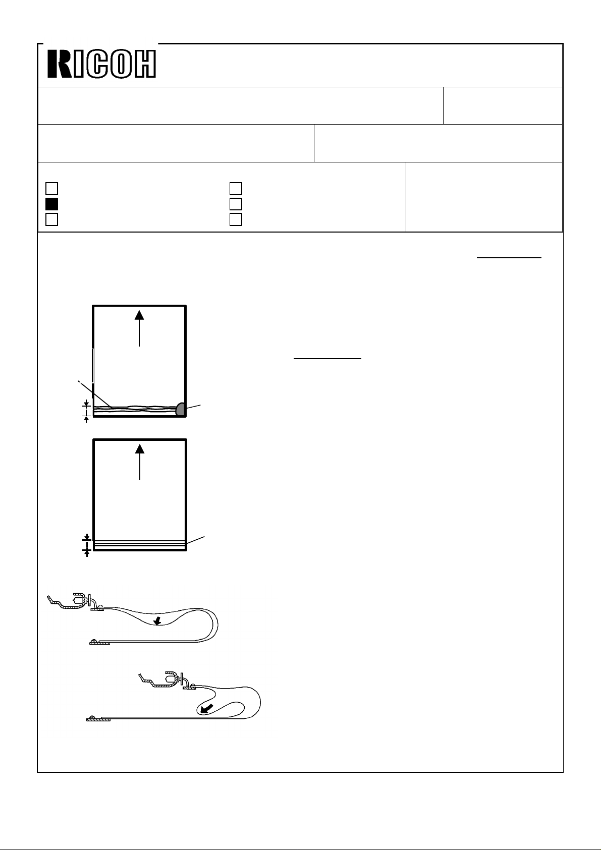
[Symptom]
The following abnormal image is obserbed only
Blurred
image
20 to
30 mm
Black mode
A3/11" x 17"
Background
in A3/11" x 17" copy;
1) Black mode
• On the corner of right-trailing edge, there is
partical dirty background.
• Or, the copy image at 20 to 30 mm from
the trailing edge is blurred.
20 to
30 mm
Full color mode
A3/11" x 17"
Misaligned
image
2) Full color mode
• The holizontal black line in 20 to 30 mm
from the trailing edge of original is copied
in two or three color lines due to
misalignment.
• In rare cases, black lines/charactors are
copied in "Blue" (Cyan + Magenta) due to
no yellow.
[Cause]
The exposure lamp cable is bent down, and
becomes in abnormal shape as shown while
scanning at full return area. In black copy with
226 mm/sec scanning, one of cables will be
bent inside the optical light path, resulting in less
drum exposure. In full color mode with 113
mm/sec scanning, the scanner will not be
smooth at full return area, resulting in
misaligned image.
Page 2
Technical Bulletin No. RTB-029
SUBJECT: Abnormal exposure lamp cable movement DATE: Nov. 30, ’90
PAGE: 2 of 2
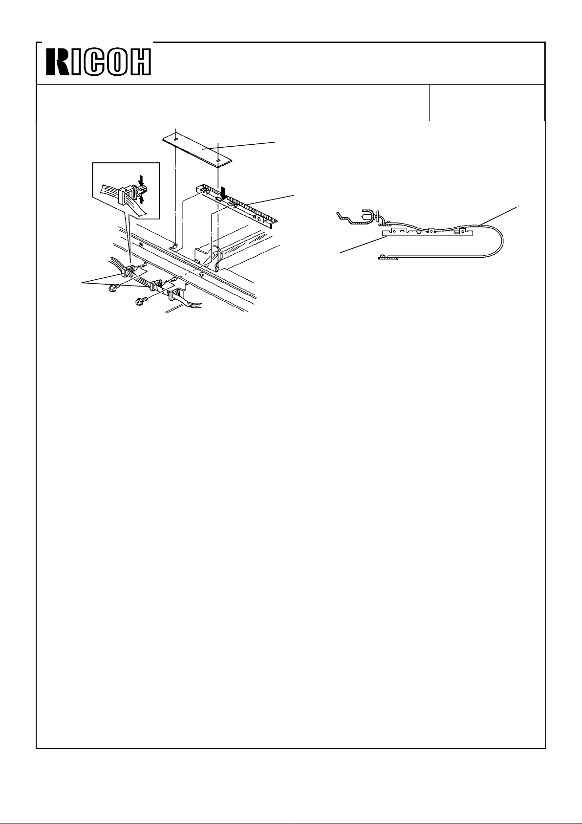
[Action]
[B]
Install the cable guide plate (P/N A0301697) using the following procedure;
1. Remove the exposure glass. (See page 5-24 of the manual.)
2. Remove the operation panel. (See page 5-119 of the manual.)
3. Remove the shielding plate [A].
4. Move the scanner to the full return position.
5. Remove two harness holders [B] from the front optics frame.
6. Using two holes for the harness holder, install the cable guide plate [C].
(Use two M4 x 6 screws with a washer.)
[A]
[C]
[C]
[D]
NOTE: 1) The surface with a piece of tape should be faced up.
2) While pressing the plate down, fix screws.
3) Position the flat cable of the exposure lamp [D] over this taped surface of
the cable guide plate.
7. While moving the scanner back to its home position manually, make sure that this plate
does not contact to the scanner.
8. Reassemble the parts removed.
NOTE: Two harness holders removed are not used.
This plate has been installed at the factory for the machines with the following
serial number onwards:
Ricoh NC100 A030-17 S/N 2520100001
-19 S/N 2520090144
-27 S/N 2520090459
-29 S/N 2520090478
Nashua C240 -16 S/N 186010XXXX
-25 S/N 1850090081
Infotec 7125 -26 S/N 3910900051
Page 3
Technical Bulletin No. RTB-031
SUBJECT: Dark full color image at 8 to 10K scans after EM or PM DATE: Nov. 30, ’90
PAGE: 1 of 1
PREPARED BY: 1. Kakegawa
CHECKED BY:
CLASSIFICATION:
Action Required
Troubleshooting
Retrofit Information
This RTB is to inform you of a mistake made by the service engineer, which has ever
experienced in field. In order to have proper VL sensor operation after the maintenance,
read the following carefully.
< SYMPTOM >
Copy image in all modes becomes very dark at 8 to 10K scans after the last maintenance
for the following ;
1). OPC drum replacement, and/or
2). Charge corona/grid wire cleaning or replacement, and/or
3). Optics cleaning, and/or
4). Exposure lamp replacement
Revision of service manual
Information only
Other
FROM: Copier Technical Support Section
MODEL: NC11
< CAUSE >
At the last visit, image adjustment for 3C and 6C was done, but not for black and the other
modes. In this case, black copy image became too light because of VL compensation
made before the above maintenance. As a result, VL sensor initial setting data was more
than 71, and no beeper sounded. If this was not found by the engineer, VL sensor has not
been operational.
< ACTION >
Refer to RTB No. 30.
< KEY SERVICE POINTS >
1. Whenever image adjustment is done, never forget to check copy image in not only
3C/6C but also black and other modes, and adjust lamp data.
2. Pay attention to beeper, or data. ( Refer to SP mode table sheet. )
Page 4
Technical Bulletin No. RTB-032
SUBJECT: Light copy in single color mode, single color erase mode, or
light black copy in area color mode ( 3C+Black, or
6C+Black )
PREPARED BY: 1. Kakegawa
CHECKED BY:
CLASSIFICATION:
Action Required
Troubleshooting
Retrofit Information
This RTB is to inform you one of the mistakes made by the service engineer after the
maintenance, which has ever experienced in field.
< SYMPTOM >
Full color copy ( 3C/6C ) and black copy are normal. But, the following copy is too light ;
---- single color
---- single color erase
---- black copy in area color mode ( 3C+Black, or 6C+Black )
Revision of service manual
Information only
Other
FROM: Copier Technical Support Section
MODEL: NC11
DATE: Nov. 30, ’90
PAGE: 1 of 1
< CAUSE >
After the following cleaning or replacement, image adjustment for 3C, 6C, and black was
done, but not for single color and the other modes;
1). OPC drum replacement, and/or
2). Charge corona/grid wire cleaning, or replacement, and/or
3). Optics cleaning, and/or
4). Exposure lamp replacement
If so, lamp data for those modes became too high after the above cleaning or
replacement. ( Refer to RTB No.30 for VL compensation. )
< ACTION >
Perform image adjustment for those modes.
< KEY SERVICE POINTS >
1. Never forget to check copy image made in those modes as well as 3C, 6C, and black
modes. If it is too light, adjust lamp data.
2. For this purpose, we recommend you to use " EM PROCEDURE LIST " in the manual.
Page 5

Technical Bulletin No. RTB-033
SUBJECT: Poor fusing in black copy DATE: Nov. 30, ’90
PAGE: 1 of 1
PREPARED BY: 1. Kakegawa
CHECKED BY:
CLASSIFICATION:
Action Required
Troubleshooting
Retrofit Information
This is an additional item to the troubleshooting manual, which has ever experienced in
field.
< SYMPTOM >
Image fusing for black copy is poor, but that for full color is normal.
< CAUSE >
Revision of service manual
Information only
Other
FROM: Copier Technical Support Section
MODEL: NC11
Image fusing in black mode ( 226mm/sec. ) is more critical than that for full color or single
color ( 113mm/sec. ) due to process speed.
Especially, under the following conditions, image fusing becomes the most critical ;
---- A3/11"x17" ( Paper length )
---- Black mode ( 226mm/sec. )
---- Continuous copy run
---- Just after warm up in the morning
---- Paper conditions ( Paper kept in cool stock room, or paper with heavy weight or rough
surface is used, and etc. )
Page 6

< ACTION >
1. First, use SP491 and change the data from "0" to "1" or "2".
SP491 : Fusing idling time/temperature shift
Data "0" : 40 sec. idling / 175 °C
"1" : 120 sec. idling / 185 °C
"2" : 200 sec. idling / 185 °C
2. If it is still poor with SP491 data "2", check and adjust fusing pressure ( NIP band ) to
the upper limit ( 7.8 to 8.0mm ).
NOTE: Never select 186 °C or more by SP49, or never adjust fusing pressure to have
wider NIP band than 8.1mm. If it is selected, toner on paper may attach on the hot
roller
( so called " Hot off set " ), or paper curl becomes more, increasing risk for
separation jam from the roller, or for hot roller damage.
Page 7

Technical Bulletin No. RTB-034
SUBJECT: Hot roller damage DATE: Nov. 30, ’90
PAGE: 1 of 1
PREPARED BY: 1. Kakegawa
CHECKED BY:
CLASSIFICATION:
Action Required
Troubleshooting
Retrofit Information
This RTB is to inform you of experienced hot roller damage. To prevent roller damage,
read the following carefully.
< SYMPTOM >
The hot roller is damaged.
< CAUSE >
Revision of service manual
Information only
Other
FROM: Copier Technical Support Section
MODEL: NC11
1. By the hot roller strippers
This is caused by paper with very smooth surface. If paper with very smooth surface is
used, copy surface becomes shine and is impressive for users. This is caused by more
heat transferred from the roller surface to paper, if it is smooth.
However, paper separation from the hot roller becomes critical, increasing the possibility of
fusing paper jam. When this type of paper jam happens, paper may push up the stripper
pawls, resulting in hot roller damage.
2. By dry paper clay or toner contamination on the oil supply pad
The other case is the roller scratches caused by dry paper clay and toner contamination
on the oil supply pad. In some kinds of paper, paper clay and toner contamination is not
wet, but dry. In this case, it is really necessary to remove contamination on the pad at
every visit.
Page 8

< ACTION >
1. Don’t use paper with very smooth surface.
Note: Never use paper for Canon CLC copiers.
2. At every visit, check and remove the contamination on the oil supply pad, and clean the
edge of the stripper pawls. Especially, if the pad is dry, replace it at around 30K
scans.
Note : It is important to perform the maintenance for both the charge corona unit and the
fusing unit at every visit !
Page 9

Technical Bulletin No. RTB-035
SUBJECT: Action to prevent the temperature in optics from becoming
too high
PREPARED BY: I. Kakegawa
CHECKED BY:
CLASSIFICATION:
Action Required
Troubleshooting
Retrofit Information
To prevent the temperature in optics from becoming too high during continuous copy run in
3C or 6C, read the following carefully and make the necessary action at the next visit
onward.
1.Possible problem
If the temperature in optics becomes too high, the thermo fuse on the exposure lamp unit
(P/N A0305379, see M/B No. 15) may be brown, or the exposure lamp may be
deteriorated.
2.Causes
Revision of service manual
Information only
Other
FROM: Copier Technical Support Section
MODEL:
NC11
DATE:March 15,’91
PAGE: 1 of 2
Due to the following causes, the temperature will be high:
1) Lamp data for 6C-H is too high.
As explained in RTB No.30, lamp data is automatically increased by VL compensation.
After the following maintenance, lamp data for black, 3C, and 6C-L was adjusted
(lowered), but that for 6C-H was not adjusted and was kept at higher data.
*Optics cleaning
*OPC drum replacement
*Charge corona unit maintenance
2) Dirty optics
Due to dirty optics, lamp data for all models becomes high.
3) Less clearance from the right side of machine to the wall (Less than 10cm)
If it is less than 10cm on the right side, air flow by the optics cooling fan is not enough.
4) Dirty optics fan filter (on the right side of optics), or dirty optics ozone filter (on the left
side of optics)
3.Action
1) Clean the charge corona and grid wires with water.
2) Check lamp data for yellow in 6C-H mode.
*6C-H "Y" standard data : 198
*6C-H "Y" data shift by one VL compensation : 6
*Therefore, this data will be changed as follows whenever VL compensation is
performed.
198 → 204 → 210 → 216 → 222
(1st) (2nd) (3rd) (4th)
Page 10

Technical Bulletin No. RTB-035
SUBJECT: DATE:March 15,’91
PAGE: 2 of 2
3) If the data is more than "222", clean the following parts in optics:
*Exposure glass
*Reflector
*All mirrors
*Lens
*Color filters
*Toner shield glass
Note : Optics cleaning is usually required at 60K PM. (Normally, two or three times VL
compensation will be performed in 60K scans.)
However, if the machines is used in dusty room, optic will be very dirty at 60K PM.
Then, there is a possibility that yellow data in 6C-H mode will be more than "222" due to
4 times compensation or more before the next 60K PM. In this case, clean the optics
once at EM visit in between 60K PM’s.
4) Perform image adjustment for all modes.
Note 1: Adjust lamp data so that copy image is in specification. Never select too high
data for lighter image, especially in black, 3C-"Y", and 6C-High modes.
*Black mode data is important for VL sensor intial setting. (See RTB No.30)
*3C-"Y", and 6C-High mode is to prevent overheat in optics.
Note 2: For
all modes, perform image adjustment.
5) Perform the following in order:
1. VL sensor adjustment (SP542)
2. VL sensor intial setting (SP547)
3. Auto ID sensor adjustment (SP56)
4. Auto ID sensor initial setting (SP57)
6) Clean the optics fan filter with a vacuum cleaner at PM. If it is very dirty, replace it.
7) Replace the optics ozone filter at 60K PM.
8) Confirm and keep at least 10cm on both rear and right sides of the machine from the
wall.
Note: 6), 7), and 8) are for good air flow in the optics.
Page 11

Technical Bulletin No. RTB-036
SUBJECT: Software Program Change - Main ROMs DATE: June 15, ’91
PAGE: 1 of 2
PREPARED BY: M. Kitajima
CHECKED BY:
CLASSIFICATION:
Action Required
Troubleshooting
Retrofit Information
OLD P/N NEW P/N
A0305108J A0305108K
A0305109J A0305109K
For NC11 machines with ROMs up to A030xxxxJ, the customer can interrupt SS mode to
make any number of copies. This can cause toner filming of the OPC drum under heavy
usage conditions.
A new SP mode has been added from ROMs A030xxxxK to enable uninterruptable SS
mode operation under certain conditions as explained below.
No. ITEM/DATA FUNCTION REMARKS DEFAULT
78-5 Copy
Restriction in
SS Mode
0: No
1: Yes
The Start key turns red and copying
is inhibited until the copier leaves SS
mode if both the following conditions
occur:
1) The job just completed is 100 or
more scans.
2) Total number of scans since the
completion of the last SS mode is
300 or more.
Revision of service manual
Information only
Other
FROM: Copier Technical Support Section
MODEL: NC11
Recommended for
customers with high
copy volume to
ensure completion
of SS mode. 0
<Cut-in Serial Number>
Machine Code Model Name Serial Number
A030-16
A030-17
A030-19
A030-25
A030-26
A030-27
A030-29
Nashua C240
Ricoh NC100
Ricoh NC100
Nashua C240
Infotec 7125
Ricoh NC100
Ricoh NC100
186106XXXX
2521050001
2521050003
1850120001
391061XXXX
2520120001
252106XXXX
Page 12

Technical Bulletin No. RTB-036
SUBJECT: Software Program Change - Main ROMs DATE: June 15, ’91
PAGE: 2 of 2
< Additional Explanation >
The conditions of performing this mode are as follows:
C1 ≥ M x 3/2 and C2 ≥ M x 1/2
M: SS Mode Interval* (Every 200 Scans)
C1: Total number of scans since the last SS mode was completed.
C2: Total number of scans in the last job.
*SS Mode Interval: The number of scans between SS mode stop and SS mode start.
Examples:
SP78-5 is set to "1", and M is 200 scans.
Black (1 Scan) Mode
Copy Quantity C1 C2 Start Key SS Mode Operation
100 100 100 Green No
+100 200 100 Green Yes
+10 210 10 Green Yes
+100 310 100 Red Yes
Full Color (3 Scan) Mode
Copy Quantity C1 C2 Start Key SS Mode Operation
70 210 210 Green Yes
+10 240 30 Green Yes
+10 270 30 Green Yes
+40 390 120 Red Yes
Page 13

Technical Bulletin No. RTB-037
SUBJECT: Deffective developer collection bag (for RICOH 115V
machines only)
PREPARED BY: S.MANO
CHECKED BY: S. Hamano
CLASSIFICATION:
Action Required
Troubleshooting
Retrofit Information
It is possible that the developer collection bag is defective (deposition at the bottom of the
bag is incomplete) and the collected developer leaks as shown.
Revision of service manual
Information only
Other
FROM: 2nd Technical Support Section
MODEL:NC11
DATE: May 15 ’94
PAGE: 1 of 1
As the result of our check in our inventory, the occurrence ratio is approximately 6%.
The suspected lot is as follows:
Color Lot number total quantity
Yellow 4003901 27 cartons (108 bags)
Magenta 4003901 79 cartons (316 bags)
Cyan 4003901 89 cartons (356 bags)
Before using the collection bags, please try to push the bottom of the bag as shown below.
If the bag is defective, the deposited part of the bottom of the bag is very easily opened.
 Loading...